1
User Manual
IPPC-9151G
Rugged Industrial Panel PC with
Intel® Core™ i7/i5/i3 Celeron
and 15" XGA TFT LCD LED
Backlight and One PCIE Slot
IPPC-9171G
Rugged Industrial Panel PC with
Intel® Core™ i7/i5/i3 Celeron
and 17" SXGA TFT LCD LED
Backlight and One PCIE Slot
Copyright
The documentation and the software included with this product are copyrighted 2011
by Advantech Co., Ltd. All rights are reserved. Advantech Co., Ltd. reserves the right
to make improvements in the products described in this manual at any time without
notice. No part of this manual may be reproduced, copied, translated or transmitted
in any form or by any means without the prior written permission of Advantech Co.,
Ltd. Information provided in this manual is intended to be accurate and reliable. However, Advantech Co., Ltd. assumes no responsibility for its use, nor for any infringements of the rights of third parties, which may result from its use.
Acknowledgements
ADAM is the trademark of Advantech Co., Ltd.
Intel and Pentium are trademarks of Intel Corporation.
IBM and PC are trademarks of International Business Machines Corporation.
Microsoft Windows is the registered trademark of Microsoft Corporation.
All other product names or trademarks are properties of their respective owners.
For more information on this and other Advantech products, please visit our website
at:
http://www.advantech.com
For technical support and service, please visit our support website at:
http://support.advantech.com
Part No. 2003915130
Edition 1
Printed in China
December 2011
IPPC-9151G/9171G User Manual
ii
Product Warranty (2 years)
Advantech warrants to you, the original purchaser, that each of its products will be
free from defects in materials and workmanship for two years from the date of purchase.
This warranty does not apply to any products which have been repaired or altered by
persons other than repair personnel authorized by Advantech, or which have been
subject to misuse, abuse, accident or improper installation. Advantech assumes no
liability under the terms of this warranty as a consequence of such events.
Because of Advantech’s high quality-control standards and rigorous testing, most of
our customers never need to use our repair service. If an Advantech product is defective, it will be repaired or replaced at no charge during the warranty period. For outof-warranty repairs, you will be billed according to the cost of replacement materials,
service time and freight. Please consult your dealer for more details.
If you think you have a defective product, follow these steps:
1. Collect all the information about the problem encountered. (For example, CPU
speed, Advantech products used, other hardware and software used, etc.) Note
anything abnormal and list any onscreen messages you get when the problem
occurs.
2. Call your dealer and describe the problem. Please have your manual, product,
and any helpful information readily available.
3. If your product is diagnosed as defective, obtain an RMA (return merchandize
authorization) number from your dealer. This allows us to process your return
more quickly.
4. Carefully pack the defective product, a fully-completed Repair and Replacement
Order Card and a photocopy proof of purchase date (such as your sales receipt)
in a shippable container. A product returned without proof of the purchase date
is not eligible for warranty service.
5. Write the RMA number visibly on the outside of the package and ship it prepaid
to your dealer.
iii
IPPC-9151G/9171G User Manual
Declaration of Conformity
CE
This product has passed the CE test for environmental specifications. Test conditions
for passing included the equipment being operated within an industrial enclosure. In
order to protect the product from being damaged by ESD (Electrostatic Discharge)
and EMI leakage, we strongly recommend the use of CE-compliant industrial enclosure products.
Warning! Any changes or modifications made to the equipment which are not
expressly approved by the relevant standards authority could void your
authority to operate the equipment.
FCC Class A
Note: This equipment has been tested and found to comply with the limits for a Class
A digital device, pursuant to part 15 of the FCC Rules. These limits are designed to
provide reasonable protection against harmful interference when the equipment is
operated in a commercial environment. This equipment generates, uses, and can
radiate radio frequency energy and, if not installed and used in accordance with the
instruction manual, may cause harmful interference to radio communications. Operation of this equipment in a residential area is likely to cause harmful interference in
which case the user will be required to correct the interference at his own expense.
Technical Support and Assistance
1.
2.
Visit the Advantech web site at http://support.advantech.com where you can find
the latest information about the product.
Contact your distributor, sales representative, or Advantech's customer service
center for technical support if you need additional assistance. Please have the
following information ready before you call:
– Product name and serial number
– Description of your peripheral attachments
– Description of your software (operating system, version, application software,
etc.)
– A complete description of the problem
– The exact wording of any error messages
Safety Precaution - Static Electricity
Follow these simple precautions to protect yourself from harm and the products from
damage.
To avoid electrical shock, always disconnect the power from your PC chassis
before you work on it. Don't touch any components on the CPU card or other
cards while the PC is on.
Disconnect power before making any configuration changes. The sudden rush
of power as you connect a jumper or install a card may damage sensitive electronic components.
IPPC-9151G/9171G User Manual
iv
Safety Instructions
1.
2.
3.
Read these safety instructions carefully.
Keep this User Manual for later reference.
Disconnect this equipment from any AC outlet before cleaning. Use a damp
cloth. Do not use liquid or spray detergents for cleaning.
4. For plug-in equipment, the power outlet socket must be located near the equipment and must be easily accessible.
5. Keep this equipment away from humidity.
6. Put this equipment on a reliable surface during installation. Dropping it or letting
it fall may cause damage.
7. The openings on the enclosure are for air convection. Protect the equipment
from overheating. DO NOT COVER THE OPENINGS.
8. Make sure the voltage of the power source is correct before connecting the
equipment to the power outlet.
9. Position the power cord so that people cannot step on it. Do not place anything
over the power cord.
10. All cautions and warnings on the equipment should be noted.
11. If the equipment is not used for a long time, disconnect it from the power source
to avoid damage by transient overvoltage.
12. Never pour any liquid into an opening. This may cause fire or electrical shock.
13. Never open the equipment. For safety reasons, the equipment should be
opened only by qualified service personnel.
14. If one of the following situations arises, get the equipment checked by service
personnel:
The power cord or plug is damaged.
Liquid has penetrated into the equipment.
The equipment has been exposed to moisture.
The equipment does not work well, or you cannot get it to work according to
the user's manual.
The equipment has been dropped and damaged.
The equipment has obvious signs of breakage.
15. DO NOT LEAVE THIS EQUIPMENT IN AN ENVIRONMENT WHERE THE
STORAGE TEMPERATURE MAY GO BELOW -20° C (-4° F) OR ABOVE 60° C
(140° F). THIS COULD DAMAGE THE EQUIPMENT. THE EQUIPMENT
SHOULD BE IN A CONTROLLED ENVIRONMENT.
16. CAUTION: DANGER OF EXPLOSION IF BATTERY IS INCORRECTLY
REPLACED. REPLACE ONLY WITH THE SAME OR EQUIVALENT TYPE
RECOMMENDED BY THE MANUFACTURER, DISCARD USED BATTERIES
ACCORDING TO THE MANUFACTURER'S INSTRUCTIONS.
The sound pressure level at the operator's position according to IEC 704-1:1982 is
no more than 70 dB (A).
DISCLAIMER: This set of instructions is given according to IEC 704-1. Advantech
disclaims all responsibility for the accuracy of any statements contained herein.
v
IPPC-9151G/9171G User Manual
IPPC-9151G/9171G User Manual
vi
Contents
Chapter
1
General Information ............................1
1.1
1.2
Introduction ............................................................................................... 2
Specifications ............................................................................................ 2
1.2.1 General ......................................................................................... 2
1.2.2 Standard PC Functions................................................................. 3
1.2.3 I/O Ports........................................................................................ 3
1.2.4 Flat Panel Interface....................................................................... 3
1.2.5 Analog Resistive Touchscreen ..................................................... 3
1.2.6 Environmental ............................................................................... 3
Dimensions ............................................................................................... 4
Figure 1.1 IPPC-9151G Dimensions ........................................... 4
Figure 1.2 IPPC-9171G Dimensions ........................................... 5
1.3
Chapter
2
System Setup .......................................7
2.1
A Quick Tour of IPPC-9151G/9171G ........................................................ 8
2.1.1 Installing CPU ............................................................................... 9
2.1.2 Installing Memory........................................................................ 11
2.1.3 Installing PCIe Card .................................................................... 12
2.1.4 Installing CFast Card .................................................................. 13
2.1.5 Installing HDD ............................................................................. 14
2.1.6 Installing PS/2 Mouse and Keyboard.......................................... 16
2.1.7 Serial COM ports ........................................................................ 16
2.1.8 VGA Port..................................................................................... 16
2.1.9 HDMI Port ................................................................................... 16
2.1.10 USB Port ..................................................................................... 16
2.1.11 Ethernet ...................................................................................... 17
2.1.12 Connecting Audio Device............................................................ 17
2.1.13 Connecting Power Cord.............................................................. 17
2.1.14 Ground Connection..................................................................... 18
2.1.15 ATX Power On Switch ................................................................ 18
Mounting Instructions .............................................................................. 19
2.2.1 Panel Mounting ........................................................................... 19
2.2.2 Rack Mounting ............................................................................ 20
Jumper Settings and Connectors............................................................ 21
2.3.1 Clear CMOS................................................................................ 21
2.3.2 ATX and AT Mode ...................................................................... 21
Table 2.1: PSON1: ATX, AT mode selection............................. 21
2.3.3 Control LVDS Backlight (JLVDS_CLT1) from SIO...................... 21
2.3.4 JLVDS1 Power Selector ............................................................. 21
2.3.5 CPU Fan Connector (CPU_FAN1) ............................................. 22
2.3.6 System Fan Connector (SYSFAN1/2) ........................................ 22
2.3.7 PWRSW (Power Switch Connector) ........................................... 23
2.3.8 SATA Interface............................................................................ 23
2.3.9 ATX Power Connector (EATXPWR1, ATX12V1)........................ 24
2.3.10 Display Backlight Connector (INV1)............................................ 25
2.3.11 LVDS Port (LVDS1) .................................................................... 25
2.3.12 GPIO Port (GPIO1) ..................................................................... 26
2.3.13 PCIe Slot..................................................................................... 26
2.2
2.3
Chapter
3
BIOS Setup .........................................27
3.1
BIOS Introduction.................................................................................... 28
vii
IPPC-9151G/9171G User Manual
3.2
3.3
3.5
3.6
3.7
Main Menu .............................................................................................. 28
Advanced BIOS Features ....................................................................... 29
3.3.1 ACPI Settings ............................................................................. 29
3.3.2 CPU Configuration...................................................................... 30
3.3.3 SATA Configuration .................................................................... 31
3.3.4 AMT Configuration...................................................................... 32
3.3.5 USB Configuration ...................................................................... 33
3.3.6 NCT3776F Super IO Configuration ............................................ 34
3.3.7 H/W Monitor................................................................................ 36
3.3.8 F81216 Super IO Configuration.................................................. 37
Chipset.................................................................................................... 38
3.4.1 System Agent (SA) Configuration............................................... 38
3.4.2 NB PCIe Configuration ............................................................... 40
3.4.3 LAN Ports Setting ....................................................................... 41
3.4.4 USB Configuration ...................................................................... 43
Boot Setting ............................................................................................ 44
Security Setting....................................................................................... 45
Save & Exit ............................................................................................. 46
4
Installing API Software ..................... 47
4.1
Brightness Control Software (SUSI) ....................................................... 48
4.1.1 Installing SUSI Software ............................................................. 48
4.1.2 Adjust LCD Brightness with SUSI............................................... 50
3.4
Chapter
IPPC-9151G/9171G User Manual
viii
Chapter
1
1
General Information
This chapter provides a general
description of the IPPC-9151G/
9171G.
Sections include:
Introduction
Specifications
Dimensions
1.1 Introduction
The IPPC-9151G/9171G industrial panel PC is especially designed to fit in space-limited environments where expansion is restricted.Its solid structure enables systems
to operate under harsh industrial conditions.
Sturdy structure
The whole system is protected by a firm solid structure. The front panel is made of
sturdy aluminum. It is shock resistant, and complies with NEMA4/IP65.The stainless
steel case (SUS304) on the rear side is rugged and corrosion resistant, and enables
the system to operate reliably in even the harshest environments.
Economical
AIMB-272 Motherboard supports Intel® Core™ i7, i5, Celeron mobile processors.IPPC-9151G/9171G's motherboard AIMB-272 supports Intel® Core™ i7, i5,
Celeron mobile processors + Intel® QM67 chipset, which is an economical and powerful platform.Its reliable performance will ensure the system to run properly in industrial environments.
Friendly HMI
Systems in the IPPC-9151/9171 series are equipped with a 15" & 17" LCD LED
backlight, which provides high resolution display quality. The result is vivid, bright,
and sharp quality images.The panel PC is perfectly suited for Windows OS.The
touchscreen version enables simple operation, making the Panel PC a solid industrial digital controller interface.
Rich I/O Ports
IPPC-9151G/9171G has rich I/O ports, supporting external display expansion.
1.2 Specifications
1.2.1 General
Dimensions (W x H x D):
– IPPC-9151G: 428 x 310 x 96.5 mm (16.35" x 12.2" x 3.79")
– IPPC-9171G: 482 x 354.8 x 98 mm (18.98" x 13.97" x 3.86")
Chassis: Aluminum front frame complies with NEMA4/IP65. SUS304 stainless
steel back case
Mounting: Rack mounting and panel mounting
Note!
For an IPPC-9151GA the rack mounting kit should be ordered separately.
Power supply: 180W MTBF 100,000 hours
Input voltage: 100-240 VAC, 50/60 Hz, 4A
Output voltage: +3.3 V @ 16.8 A, +5 V @ 12.0 A, +12 V @ 10.0 A
System Cooling Fan Dimensions (W x H x D): 60 x 60 x 10.5 mm (2.36" x
2.36" x 0.41")
OS Support: Windows XP/ Windows 7
Weight:
– IPPC-9151G:10.52 kg (23.19 lbs)
– IPPC-9171G: 14 kg (30.86 lbs)
IPPC-9151G/9171G User Manual
2
1.2.3 I/O Ports
Serial ports: Four RS-232 ports (COM1, COM2, COM3, COM4)
Ethernet Ports (LAN): Supports two GbE LAN ports
LAN1: Intel 82579LM; LAN2: Intel 82583V
Audio interface: Supports one line-in, one line-out and one mic-in
VGA interface: Supports one standard 15-pin D-SUB port
HD HDMI interface: Supports one standard HDMI port
LVDS: Default LVDS
– - IPPC-9151G: Supports 1024 * 768, 24bit
– - IPPC-9171G: Supports 1280 * 1024, 48bit
Universal serial bus (USB) port: Supports five USB (version 2.0) ports, four
one the rear panel and one on the front panel
1.2.4 Flat Panel Interface
Display type: Simultaneously supports CRT + LVDS or HDMI + CRT or LVDS +
HDMI
Display resolution:
– IPPC-9151G: 1024 * 768 24-bit
– IPPC-9171G: 1280 * 1024 48-bit
1.2.5 Analog Resistive Touchscreen
Type: Analog resistive
Light Transmission: >80%
Controller: USB interface (use USB5)
Resolution: 2048 x 2048
1.2.6 Environmental
Operating temperature: 0 ~ 50°C(32 ~ 122°F)
Storage temperature: -20 ~ 60°C(-4 ~ 140°F)
Relative humidity: 10 ~ 90% @ 40°C (non-condensing)
Shock: 30 G peak acceleration (11 ms duration)
Power MTBF: 100,000 hrs
3
IPPC-9151G/9171G User Manual
General Information
CPU: Intel® Core™ i7/i5/i3 Celeron Æ µFC-PGA988 Core i7-2710QE 2.1 GHz/
Core i5-2510E 2.5 GHz/Core i3-2330E 2.2 GHz/Celeron B810 1.6GHz Mobile
Processors
RAM: Up to 8 G in 2 204-pin SODIMM sockets, supports DDR3 1066/1333
SDRAM (2 x 4 GB)
Keyboard and mouse ports (PS2): Supports one PS2 port (for keyboard and
mouse)
Storage:
– CFast: Supports one CFast
– HDD: Supports one 2.5" SATAII or SATA III HDD
Watchdog timer: 60-level, interval 1 ~ 60 seconds.Automatically generates
system reset when the system stops due to a program error or EMI.
Battery: 3.0 V @ 195 mA lithium battery
Expansion slots: One PCIe slot and one PCIe x16 slot for 1 x PCIe x1 or x4
(Gen 2) add-on card
Chapter 1
1.2.2 Standard PC Functions
Certifications: CE, CCC, FCC Class A; meets UL, BSMI
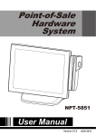
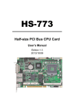
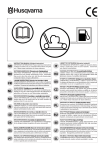
1.3 Dimensions
Panel Cut-out Dimension: 404 mm (15.90") x 292 mm (11.49")
Figure 1.1 IPPC-9151G Dimensions
IPPC-9151G/9171G User Manual
4
Chapter 1
General Information
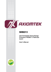
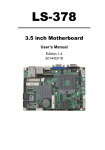
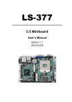
Panel Cut-out Dimension: 447 mm (17.618") x 329.50 mm (12.972")
Figure 1.2 IPPC-9171G Dimensions
5
IPPC-9151G/9171G User Manual
IPPC-9151G/9171G User Manual
6
Chapter
2
2
System Setup
This chapter details system setup
for the IPPC-9151G/9171G Series.
Sections include:
A Quick Tour of IPPC-9151G/
9171G
Installing CPU
Installing Memory Card
Installing PCIe Card
Installing CFast Card
Installing HDD
Mounting Instructions
Jumpers and Connectors
2.1 A Quick Tour of IPPC-9151G/9171G
Before you start the computer, please follow these procedures to set up the system.
1. Connect the wires, cables and accessories.
2. Mount the computer.
3. Install an operating system.
Warning! 1.
2.
Switch off and unplug the computer every time you access its interior.
The motherboard inside the system is composed of many delicate
ICs, chips and other integrated circuit components. These components are easily damaged by static shock.When you begin to install
components:
- Avoid touching metal parts of the motherboard.
- Wear an anti-static ring when handling a CPU or SDRAM module.
- Put SDRAM modules and the CPU inside an anti-static bag or a
similar place before installation.
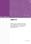
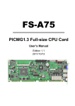
1.
Unscrew the six screws.
2.
Remove the rear cover, refer to the below figure.
COM3 COM4
COM1
Mouse
Power button GND
Power
connector
Keyboard COM2 HDMI
IPPC-9151G/9171G User Manual
8
Line in & Line
LAN out & Mic
USB
PCIe
CFast
Chapter 2
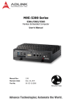
2.1.1 Installing CPU
Unplug power cable of CPU fan.
2.
Loosen four screws and take off CPU fan.
System Setup
1.
9
IPPC-9151G/9171G User Manual
3.
Take thermal grease out of the accessary box and apply evenly on CPU. Insert
CPU into the socket (pay attention to the direction of both). Fasten the screws
with screwdriver to secure the CPU.
IPPC-9151G/9171G User Manual
10
Re-install the CPU's cooling fan & then attach CPU fan power cable.
Chapter 2
4.
System Setup
2.1.2 Installing Memory
1.
Pull the two white eject levers of the ends of the memory socket. Note: select
the first socket (DIMMA) if you only want to insert one memory card.
11
IPPC-9151G/9171G User Manual
2.
Insert the memory (pay attention to the direction of the memory into the socket.
Push the two eject levers toward the vertical posts at each end of the socket
until the module is upright.
2.1.3 Installing PCIe Card
1.
Remove the screws on PCI cover, then insert PCIe card and fasten the screws.
IPPC-9151G/9171G User Manual
12
Detach the two screws of CFast cover, then take off the cover.
2.
Insert CFast card (notice the direction of the CFast card), (the interior slot), then
replace the cover.
System Setup
1.
Chapter 2
2.1.4 Installing CFast Card
13
IPPC-9151G/9171G User Manual
2.1.5 Installing HDD
1.
Remove four screws and remove the HDD bracket.
2.
Take four M3 screws out of the accessary box and insert HDD into HDD bracket
(pay attention to the direction of HDD).
IPPC-9151G/9171G User Manual
14
Chapter 2
System Setup
3.
Put the HDD bracket into the chassis and fasten the four screws. Then attach
the HDD flat cable and power cable.
15
IPPC-9151G/9171G User Manual
2.1.6 Installing PS/2 Mouse and Keyboard
Attach the PS/2 keyboard and mouse adapter to the chassis (pay attention to the
direction of the keyboard and mouse).
2.1.7 Serial COM ports
There are four serial COM ports on the I/O section of the rear cover. You can easily
attach a serial device according to the application requirements. Remember to refix
the screws.
2.1.8 VGA Port
An external VGA-compatible device may be connected to the system via the 15-pin
external port located on the bottom of the system unit. Remember to refix the screws
after connecting any device via this port.
2.1.9 HDMI Port
An external HDMI device may be connected to the system. Pay attention to the direction of the port. Remember to fasten the screws to protect the data cable from loosing.
2.1.10 USB Port
An external USB device may be connected to the system via the 4 USB ports located
on the bottom side of the system unit and one on the front panel.The USB ports support hot plug-in connection.For high-power USB device, use an external power supply.
IPPC-9151G/9171G User Manual
16
Connect the Ethernet cable to LAN port. Note: If the distance between the network
cable and the device is to far it will result in the network cannot be connected. Add a
HUB to enhance the network signal as needed.
LAN LED Indicators:
LAN mode
LAN LED
LED1 (right)
LAN2 LED
Off when connection error occurs; Linked (On)/
Active (Blinking)
LED2 (left)
100 Mbps(On)/10 Mbps (Off)
LED2 (left)
1000 Mbps (On)
LED2 (right)
Off when connection error occurs; Linked (On)/
Active (Blinking)
LED2 (left)
100 Mbps(On)/10 Mbps (Off)
LED2 (left)
1000 Mbps (On)
2.1.12 Connecting Audio Device
The audio interface includes three jacks: line-in, line-out and Mic-in. Attach the
device when needed.
2.1.13 Connecting Power Cord
Remove the power cord bracket, then plug in the standard power cord. Replace the
bracket and fasten the screws. Note: Pay attention to the input voltage of the power
supply.
17
IPPC-9151G/9171G User Manual
System Setup
LAN1 LED
Chapter 2
2.1.11 Ethernet
2.1.14 Ground Connection
For the safety of the operator and the device, connect the ground wire.
Location of the ground wire:
2.1.15 ATX Power On Switch
IPPC-9151G/9171G User Manual
18
There are two ways to mount the system: panel mounting or rack mounting.
2.2.1 Panel Mounting
1.
2.
3.
Note!
Panel's maximum thickness is 5 mm.
19
IPPC-9151G/9171G User Manual
System Setup
Take the four mounting brackets out of the accessory box.
Attach the four mounting brackets by inserting the screws into the keyhole slots
on the cover of the monitor.
Use the screws to secure the brackets to the cover. Tighten the screws to
secure the monitor to the back panel.
Chapter 2
2.2 Mounting Instructions
2.2.2 Rack Mounting
IPPC-9151G users can optionally order 19" industrial rack mounting kit. The part
number is IPPC-9151G-R1MKE.
IPPC-9171G can be directly mounted to a 19" industrial rack. Remove the rubber on
the panel.
IPPC-9151G/9171G User Manual
20
Chapter 2
2.3 Jumper Settings and Connectors
2.3.1 Clear CMOS
Function
Jumper setting
1-2 closed
* Clear CMOS data
2-3 closed
* Default
Note!
If password is set in CMOS, the above way can not clear the password.
Only by refreshing BIOS can the password be cleared.
2.3.2 ATX and AT Mode
Table 2.1: PSON1: ATX, AT mode selection
Close Pins
Result
1-2
AT mode
2-3*
ATX mode
* Default
2.3.3 Control LVDS Backlight (JLVDS_CLT1) from SIO
1
2
3
Linear brightness control
1 and 2
1
2
PWM brightness control (default)
3
2 and 3
2.3.4 JLVDS1 Power Selector
- IPPC-9151G: Default 4-6, 3.3 V
- IPPC-9171G: Default 2-4, 5 V
Close Pins
Result
JLVDS1
2-4
For jumpers of 5 V LVDS panel
4-6
For jumpers of 3.3V LVDS panel
3-4
For jumpers of 12 V LVDS panel
21
IPPC-9151G/9171G User Manual
System Setup
* Keep CMOS data
2.3.5 CPU Fan Connector (CPU_FAN1)
If a fan is used, this connector supports cooling fans of 500 mA (6 W) or less.
2.3.6 System Fan Connector (SYSFAN1/2)
Note!
System fan has no signal detection, so the fan speed will not show in
CMOS.
IPPC-9151G/9171G User Manual
22
Chapter 2
System Setup
If a fan is used, this connector supports cooling fans of 500 mA (6 W) or less.
2.3.7 PWRSW (Power Switch Connector)
If your computer case is equipped with an ATX power supply, you should connect the
power on/off button on your computer case to (JFP1/ PWR_SW).
2.3.8 SATA Interface
The blue one is for SATA 3.0 interface(1.2), the black one is for SATA2.0 interface(3.4).
23
IPPC-9151G/9171G User Manual
Default: SATA1 for HDD
SATA2 for CFast board.
2.3.9 ATX Power Connector (EATXPWR1, ATX12V1)
IPPC-9151G/9171G User Manual
24
Chapter 2
2.3.10 Display Backlight Connector (INV1)
System Setup
2.3.11 LVDS Port (LVDS1)
25
IPPC-9151G/9171G User Manual
2.3.12 GPIO Port (GPIO1)
2.3.13 PCIe Slot
Note!
Intel QM67 chipset supports PCIe x16 slot (Gen 2.0), but it still has
some compatibility issues with certain interface cards.
IPPC-9151G/9171G User Manual
26
Chapter
3
BIOS Setup
3
3.1 BIOS Introduction
IPPC-9151G/9171G has AMI EFI 64 Mbit SPI BIOS, with a CMOS SETUP utility that
allows users to configure required settings or to activate certain system features.
When the power is turned on, pressing the <Del> button or F2 will take you to the
CMOS SETUP screen.Functions of the control keys in CMOS screen:
→←
Move to selected screen
↑↓
Move to selected item
Enter
Select item
+/-
Change Opt.
F1
General help
F2
Previous values
F3
Optimized default
F4
Save and exit
ESC
Exit
3.2 Main Menu
It displays information about BIOS version, etc. The user can use this option to
change the system time and date.
Highlight System Time or System Date using the <Arrow> keys. Enter new values
through the keyboard. Press the <Tab> key or the <Arrow> keys to move between
fields.The date must be entered in MM/DD/YY format. The time must be entered in
HH:MM:SS format.
IPPC-9151G/9171G User Manual
28
Chapter 3
3.3 Advanced BIOS Features
BIOS Setup
3.3.1 ACPI Settings
29
IPPC-9151G/9171G User Manual
Enable ACPI Auto Configuration
The default setting is "Enabled".ACPI is short for Advanced Configuration and
Power Interface.
Wake system with Fixed Time
The default setting is "Disabled".
PowerOn by Modem
The default setting is "Disabled".
Power Type
The power type is ATX. (This cannot be modified)
3.3.2 CPU Configuration
The information depends on CPU model.
Active Processor Cores [ALL]
Active multi-core processors. The default setting is “ALL”.
Limit CPUID Maximum [Disabled]
This item allows you to limit CPUID maximum value. The default setting is “Disabled”.
Execute Disable Bit [Enabled]
This item allows you to enable or disable the No-Execution page protection
technology. The default setting is “Enabled”.
Hardware Prefetcher [Enabled]
Hardware detection. The default setting is “Enabled”.
Adjacent Cache Line Prefetch [Enabled]
This item allows users to enable or disable the adjacent cache line prefetcher
feature. The default setting is “Enabled”.
IPPC-9151G/9171G User Manual
30
Intel Virtualization Technology [Disabled]
Intel Virtualization Technology (Intel VT) is a set of hardware enhancements to
Intel server and client platforms that provide software-based virtualization solutions. The default setting is “Disabled”.
You can enable or disable Intel Virtualization Technology as required
Chapter 3
3.3.3 SATA Configuration
BIOS Setup
SATA Controllers
The default setting is “Enabled”.
SATA mode cannot be selected if this item is disabled.
SATA Mode Selection
SATA Mode Selection. The default setting is “IDE”. It can be configured as other
mode (IDE AHCI RAID) if required.
Serial ATA Port
Serial ATA Port displays all connected HDDs.
31
IPPC-9151G/9171G User Manual
3.3.4 AMT Configuration
Intel AMT [Enabled]
The default setting is “Enabled”.
Intel AMT Setup Prompt [Enabled]
This item allows users to enable or disable Intel AMT Setup prompt. The default
setting is “Enabled”.
BIOS Hotkey pressed [Disabled]
The default setting is “Disabled”.
MEBx Selection Screen [Disabled]
Intel Management Engine BIOS Extension (MEBx).This item allows users to
enable or disable MEBx selection screen. The default setting is "Disabled".
Verbose Mebx Output [Enabled]
This item allows users to enable or disable MEBx Output. The default setting is
“Enabled”.
Hide Un-Configure ME Confirmation [Disabled]
This item allows users to hide un-configured ME without password confirmation
prompt. The default setting is “Disabled”.
MEBx Debug Message Output [Disabled]
This item allows users to enable or disable MEBx debug message. The default
setting is “Disabled”.
Un-Configure ME [Disable]
The default setting is “Disabled”.
Intel AMT Password Write Enabled [Enabled]
This item allows users to enable or disable Intel AMT password write. The
default setting is “Enabled”.
AMT Wait Time
Set waiting time to enter AMT to 0.The default setting of ASF is “Enabled”.ASF
is short for Advanced Streaming Format.
IPPC-9151G/9171G User Manual
32
3.3.5 USB Configuration
Legacy USB Support [Enabled]
The user can enable or disable this function. The default setting is “Enabled”.
EHCI Hand-off [Disabled]
The default setting of EHCI (Enhanced Host Controller Interface) is “Disabled”.
USB Transfer time-out[20sec]
The default time interval is 20 seconds. The other options include 1sec, 5sec,
10sec and 20sec.
Device reset time-out[20sec]
The default time interval is 20 seconds. The other options include 10sec, 20sec,
30sec and 40sec.
Device power-up delay [auto]
The default setting is “Auto”. The user can choose “Auto” or “Manual”.
33
IPPC-9151G/9171G User Manual
BIOS Setup
Activate Remote Assistance Process [Disabled]
The default setting is “Disabled”.
USB Configure [Enabled]
The default setting is “Enabled”.
PET Progress [Enabled]
The default setting is “Enabled”.
Intel AMT SPI Protected [Disabled]
The default setting is “Disabled”.
Watch Dog [Disable]
The default setting is “Disabled”. Users can enable this item when needed.
Chapter 3
3.3.6 NCT3776F Super IO Configuration
COM1, COM2 Port Configuration
Serial Port1 Configuration
COM1 port address configuration
Serial Port [Enabled]
The default setting is “Enabled”.COM1 address: 3F8h;IRQ=4.
Charge Settings [AUTO]
The user can change COM1 address as required.
IPPC-9151G/9171G User Manual
34
Serial Port2 Configuration
Serial Port [Enabled]
The default setting is “Enabled”.
COM2 address: 2F8h;IRQ=3.
Charge Settings [AUTO]
The user can change COM2 address as required.
Device Mode [Standard Serial Port Mode]
The default setting is “Standard Serial Port Mode”.Ths user can change to other
modes as required.
Chapter 3
BIOS Setup
35
IPPC-9151G/9171G User Manual
3.3.7 H/W Monitor
CPU Temperature
This shows you the current CPU temperature.
System Temperature
This shows you the current temperature of system.
CPU FAN Speed
This shows the current CPU FAN operating speed.
System1 FAN Speed
This shows the current System1 FAN operating speed.
System2 FAN Speed
This shows the current System2 FAN operating speed.
Vcore/+12V/ +5V/ 5VSB/+3.3V/AVCC/VSB3/VBAT
This shows the voltage of VCORE, +12V, +5V, 5VSB(V), +3.3V, AVCC, VSB3
and VBAT(V).
System Smart Fan
(Note: System fan has no signal detection wire, so the fan speed can not be
detected),
Case Open Warning [Disabled]
The user will be able to find the failure by sound alarm if this item is enabled.
CPU Warning Temperature [Disabled]
This item allows you to set CPU warning temperature. The default setting is
“Disabled”.
ACPI Shutdown Temperature [Disabled]
This item allows you to set ACPI Shutdown Temperature. The default setting is
“Disabled”.
IPPC-9151G/9171G User Manual
36
Chapter 3
3.3.8 F81216 Super IO Configuration
COM3 and COM4 configuration.
IPPC-9151G/9171G can support four COM ports.
BIOS Setup
Serial Port 3 Configuration
COM3 Setting. This user can change COM3 address as required. The default
setting is “Auto”.
Serial Port 4 Configuration
COM4 port address configuration.Ths user can change COM4 address as
required. The default setting is “Auto”.
37
IPPC-9151G/9171G User Manual
3.4 Chipset
Chipset Configuration Setting
3.4.1 System Agent (SA) Configuration
3.4.1.1 Graphics Configuration
IPPC-9151G/9171G User Manual
38
Chapter 3
BIOS Setup
LCD Control
Primary IGFX Boot Display [LVDS]
The primary display item is LVDS display by default.
Secondary IGFX Boot Display [CRT]
The secondary display item is CRT display by default. Choosing “VBIOS
Default“ will result in blurred screen. It’s recommended to use the default LVDS.
LCD Panel Type [1024x768 LVDS,24Bit]
(Default setting of IPPC-9151)
LCD Panel Type[1280x1024 LCDS,48Bit]
(Default setting of IPPC-9171)
VBIOS Default values are neither 24 bit nor 48 bit. Choosing “VBIOS Default“
will result in blurred screen. It’s recommended to use the default BIOS values.
Panel Scaling [AUTO]
This item allows users to enable or disable the panel scaling feature. The
default setting is “Auto”.
Active LFP [Int-LVDS]
This item allows users to select LFP configuration. The default setting is LVDS.
VBIOS Default values are neither 24 bit nor 48 bit. Choosing “VBIOS Default“
will result in blurred screen. It’s recommended to use the default LVDS.
39
IPPC-9151G/9171G User Manual
3.4.2 NB PCIe Configuration
PCIe slot configuration
PEG0-GENX [Gen1]
The default setting is Gen1.
Always Enable PEG [Disabled]
The default setting is “Disabled”. Users can enable this item when needed.
PEG ASPM [Disabled]
Active State Power Management. Power management solution supported by
WIN7 and VISTA. Power saving mode will be used when the device (PCI
Express) is idle.The default setting is “Disabled”.
IPPC-9151G/9171G User Manual
40
Chapter 3
BIOS Setup
3.4.3 LAN Ports Setting
LAN1 Controller [Enabled]
The default setting of LAN1 port is “Enabled”.
LAN1 Option-ROM [Disabled]
The default setting is “Disabled”.
Wake on LAN1 from S5[Disabled]
The default setting is “Disabled”.
41
IPPC-9151G/9171G User Manual
LAN2 Controller [Enabled]
The default setting of LAN2 port is “Enabled”.
LAN2 Option-ROM [Disabled]
The default setting is “Disabled”.
Wake on LAN1 from S5[Disabled]
The default setting is “Disabled”.
Azalia Internal HDMI Codec [Enabled]
The default setting is “Enabled”.
High Precision Timer {Enabled]
The default setting is “Enabled”.
SLP-S4 Assertion Width[4-5 Seconds]
SLP (Software Licensing and Protection)
SLP detection uses 4-5 seconds.
Restore AC Power-Loss [Power Off]
The computer will not restart when AC power is restored after power-loss. The
user can this the setting if required.
IPPC-9151G/9171G User Manual
42
The default setting off EHCI1 is “Enabled”.
The default setting off EHCI2 is “Enabled”.
USB Ports Per-Port Disabled Control [Disabled]
The default setting is “Disabled”.
Chapter 3
3.4.4 USB Configuration
BIOS Setup
43
IPPC-9151G/9171G User Manual
3.5 Boot Setting
Bootup NumLock State [On]
When “ON”, the keyboard NumLock state will stay “ON” after booting. The
default setting is “ON”.
This user can change the setting as required.
Option ROM Messages [force BIOS]
The default setting is “force BIOS”.
Interrupt 19 Capture [Disabled]
The default setting is “Disabled”.
IPPC-9151G/9171G User Manual
44
Boot Option #1
Boot Option #2
Show different boot device choices.
Hard Drive BBS Priorities
Select the main hard disk device type to be a boot hard drive.
3.6 Security Setting
Chapter 3
BIOS Setup
Administrator Password
Set the Administrator password.
User Password
Set the User password.
45
IPPC-9151G/9171G User Manual
3.7 Save & Exit
Save Changes and Exit
Save Configuration Changes and Exit Now? Select “OK” or “Cancel”.
Discard Changes and Exit
Discard Changes and Exit Setup Now? Select “OK” or “Cancel”.
Restore Default
The BIOS automatically configures all setup items to optimal settings when
users select this option.
Save as User Defaults
Save the all current settings as a user default.
Restore User Defaults
IPPC-9151G/9171G User Manual
46
Chapter
4
4
Installing API Software
4.1 Brightness Control Software (SUSI)
4.1.1 Installing SUSI Software
(SUSI software can be downloaded from our advantech website.)
1. Click “Setup” to install SUSI software.
2. Click “Next”.
3.
Select “I accept the terms of the license agreement”, then click “Next”.
IPPC-9151G/9171G User Manual
48
Click “Install”.
5.
Select “Yes, i want to restart my computer now” and click “Finish”.
Chapter 4
4.
IPPC-9151G/9171G User Manual
Installing API Software
49
4.1.2 Adjust LCD Brightness with SUSI
1.
Launch SUSI software.
2.
The following screen appears:
IPPC-9151G/9171G User Manual
50
Select “Display” as shown below:
4.
Drag the slider with the mouse or click Up/Down button to adjust the brightness
of LVDS display.
For IPPC-9151G, the lower the slider is, the brighter LVDS display
will be.
For IPPC-9171G, the lower the slider is, the darker LVDS display
will be.
51
IPPC-9151G/9171G User Manual
Installing API Software
Note!
Chapter 4
3.
www.advantech.com
Please verify specifications before quoting. This guide is intended for reference
purposes only.
All product specifications are subject to change without notice.
No part of this publication may be reproduced in any form or by any means,
electronic, photocopying, recording or otherwise, without prior written permission of the publisher.
All brand and product names are trademarks or registered trademarks of their
respective companies.
© Advantech Co., Ltd. 2011