1
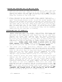
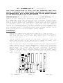
RAMBOard(tm) Installation
1571
READ THESE INSTRUCTIONS AT LEAST ONCE AND UNDERSTAND THEM FULLY
BEFORE ATTEMPTING THIS MODIFICATION. NEITHER THE DISTRIBUTOR, OR
THE MANUFACTURER WILL BE HELD RESPONSIBLE FOR ANY DAMAGE INCURRED
IN THE INSTALLATION OR USE OF THIS PRODUCT.
WARNING!:This modification will void ANY Warranty now in
effect on your disk drive. Proceed at your own risk.
All RAMBOards have been tested and are in proper working order
before we ship them. Please remember that you will be working with
static sensitive devices, so prepare a work area with this in mind
(a grounding source, no rugs, etc.). Also note that the RAMBOard
itself is a fragile device. The pins are easily bent and may break
off if not inserted properly. If after installing the RAMBOard the
test program shows a non-functioning unit, please contact us as
soon as possible at the Tech Support phone number.
PREPARATION:
1. Unplug all cables from the drive and turn it over so the
bottom is facing up. Remove the four screws from the bottom of
the case. Be sure to put them away where you'll be able to
locate them later.
2.
While holding both halves of the case, carefully turn the
drive over so the top of the drive is facing up. Next, lift
the top half of the case off and lay it aside.
3. Now, locate and remove the four screws holding the perforated
power supply cage in place. When done, remove it's electrical
connector at board location CN1. For reassembly purposes,
notice that the flange end of that connector is pointed
towards the outside of the PC board. Locate and remove the
screws in the all metal grounding strap tying the power supply
cage to the drive unit. Lift out the power supply from the
lower case half.
R19
R30
Q3
E
E
CIA
R22
CR3
CR4
CR5
CR6
CR7
CR8
CR9
C6
C8
Q2
U7
R10
R17
TP1
TP2
U11
R34
U13
U4
U6
C16
C13
U9
U16
C4
EMI4
EMI3
EMI2
EMI1
U14
U21
C28
U20
U3
C19
U19
1
U1
U2
ROM
U8 C11
R35
C14
L3
R33
R32
C27
C15
U15
CR13
R15
C3
1571 RAMBOard
C2
RP1
SW1
CN6
CN8
R36
R28
R27
R25
R26
C9
PAGE [1]
(c)
1989 CLD
FINDING AND REMOVING THE CIA AND ROM CHIPS:
1. Position the drive so that the front faces to your right and
the rear to your left. Referring to the diagram on page one,
locate and remove the CIA chip at board location U20, and the
ROM chip at board location U2. Notice that the notches on both
chips are located on the right end.
2. After identifying the CIA and ROM chips, remove them with
a chip puller. If you don't have a chip puller, you may use a
small flat-bladed pocket knife. Place the blade between the
chip and the socket and rotate the blade. The chip will lift
slightly at one end of the socket. Now repeat the procedure at
the other end of the chip. Keep doing this until you can pull
the chip straight out of the socket. Be patient! You DO NOT
want to bend the pins on the chip! If you do bend the pins
slightly, you may be able to straighten them, but be CAREFUL,
these pins do not take well to bending.
INSTALLING THE 1571 RAMBOard:
1.
After removing the two chips, and before beginning the
installation procedure, thoroughly inspect your 1571 RAMBOard.
The pins on the underside (Yes there are two cut off) will
replace the chips just removed from the board. Carefully
position the two boards into the empty sockets, making sure
all pins line up properly. You may have to gently bend over
some of the small round green or brown capacitors to provide
clearance, so now is the time to check things out. When all
looks o.k., firmly press each board in place until it fits
flush against it's socket. Most problems will be avoided if
you are certain that the two boards are PROPERLY SEATED.
2.
Now place the chips, previously removed, into the empty
sockets on the 1571 RAMBOard using the same caution as before.
Remember the notch placement! The notch should be facing the
front of the drive just as they were before you removed them.
Press down on the cable tying the two RAMBOard PC boards
together. Check for any damage (broken capacitors, etc.) or
improper chip placement before going on to the next step.
3. Now, carefully place the power supply back into position and
replace the two screws on the left hand side of the power
supply (looking from the back). The two screws remaining may
now be replaced but do not over-tighten. Because of extreme
clearance limitations, the power supply will now be touching
the chips in the 1571 RAMBOard. This will not cause any
problems and will actually act as a heat sink for the CIA
chip, which runs hot during normal drive operation. Again, DO
NOT try to snug the drive screws down tight. Finally, replace
the power supply electrical connector at board position CN1
(remember the flanges point to the outside of the PC board),
and the grounding strap in it's former location.
1571 RAMBOard
PAGE [2]
(c)
1989 CLD
TESTING AND FINAL ASSEMBLY:
1. Before refitting the upper half of the drive case, connect the
power cable and turn on the drive. If anything abnormal
happens quickly turn the drive off. Remove the power supply
and, once again, check for any visible damage or improper chip
placement. If nothing abnormal happened, turn off the drive
and go to the next step.
2. Connect the drive to the computer and run the test program
(see below). If the program reports that the RAMBOard is not
functioning properly, call the Technical Support line as soon
as possible and we will try and resolve the problem. The
technical support phone number is (206) 695-9648. Support is
available Mon - Fri 9am-5pm Pacific Time.
3. If all checks out well with the test program, turn off the
computer and drive. Remove all cables from the drive and
replace the upper half of the drive case. Carefully turn the
drive over and replace the four screws. Reconnect the power
and serial cables and use the drive as normal.
RAMBOard UTILITIES DISK:
All utilities run in the 64 mode!
RAMBOard Test Program: The diskette that was packed along with
your RAMBOard contains, among other things, an installation test
program. With the RAMBOard Utilities diskette in the drive, type
LOAD "RAMBOARD TEST " ,8,1 and press RETURN. At the READY prompt,
type RUN and hit RETURN again. At this point, follow on screen
prompts to determine if your RAMBoard is properly installed.
Please note that the 1571 RAMBOard adds RAM to your drive at
location $6000. Because the Maverick 8K parameters default to
$8000, you will have to change the RAM location settings.
1541 Fast Data Copiers: With the RAMBOard Utilities diskette in
the drive, type LOAD ":*" ,8,1 and press RETURN. At the READY
prompt, type RUN and hit RETURN again. You will be presented with
a menu asking if you wish the single or dual drive version of the
Fast Data Copier. Press the 1 or 2 key to load the appropriate
copier. Once the desired copier has loaded, a quick study of the
menu screen will familiarize you with the options available.
The copiers included with The RAMBOard have been designed to
efficiently copy non-protected data from one diskette to another.
They were not designed to handle copy protected programs. For that
purpose, we strongly suggest the Maverick, also available from
Software Support International. The Maverick software contains the
parameter support for your 1571 RAMBOard. This combination of
software & hardware is most powerful archiver ever developed for
the Commodore 64/128.
1571 RAMBOard
PAGE [3]
(c)
1989 CLD
Parallel Support: Your 1571 RAMBOard is equipped with a parallel
cable connector. We have already begun work on an all new parallel
utility package that will be supported through the Maverick. We'll
keep you posted.
ATTENTION C-128D OWNERS
The 1571 RAMBOard is for external drives only. It will not install
in the internal drive in your C-128D.
LIMITED WARRANTY
If at any time within 90 days of purchase, the RAMBOard or
it's companion diskette become defective (abuse not included), you
may use the blue return sheet included with your invoice to
receive a replacement unit. We will repair or replace your
defective RAMBOard as soon as possible. Replacements will be given
at no charge, upon receipt of the defective item, postage paid.
The 1571 RAMBOard
Hardware Design :(c) Chip Level Design
RAMBOard Test Program :(c) Chip Level Designs
1541/71 Fast Copiers :(c) K.J.P.B.
Distributed By
Software Support International
2700 N.E. Andresen Rd. Suite #A-1
Vancouver, Washington 98661
Order Line : 1 (800) 356-1179
Technical Line : (206) 695-9648
1571 RAMBOard
PAGE [4]
(c)
1989 CLD