1
version 1.5
ArcPower 48 TC
Table of contents
1. Safety instructions.......................................................................................................... 3
2. Operating determinations............................................................................................... 3
3.Description of the ArcPower 48 TC................................................................................ 4
4.Installation........................................................................................................................ 4
4.1.Connection to the mains............................................................................................. 4
4.2.Mounting the ArcPower 48 TC.................................................................................... 5
5.Installing instructions...................................................................................................... 5
5.1.DMX operating............................................................................................................ 5
5.2.Master-slave operating................................................................................................ 6
6.ArcPower 48 TC - DMX protocol .................................................................................... 7
7.Control board.................................................................................................................... 8
7.1 Fixture Address .......................................................................................................... 8
7.2 Fixture information...................................................................................................... 8
7.3 Personality.................................................................................................................. 9
7.4 Manual mode............................................................................................................ 10
7.5 Test sequences......................................................................................................... 10
7.6 Stand-alone setting .................................................................................................. 10
7.7 Special functions....................................................................................................... 11
8.Technical Specifications:.............................................................................................. 13
9 Replacing the fuse ........................................................................................................ 13
CAUTION!
Unplug mains lead before opening the housing!
FOR YOUR OWN SAFETY, PLEASE READ THIS USER MANUAL CAREFULLY
BEFORE YOU INITIAL START - UP!
1. Safety instructions
Every person involved with installation and maintenance of this product has to:
- be qualilfied
- follow the instructions of this manual
CAUTION!
Be careful with your operations. With a high voltage you can suffer
a dangerous electric shock when touching the wires inside the unit!
This product has left our premises in absolutely perfect condition. In order to maintain this condition and to
ensure a safe operation, it is absolutely necessary for the user to follow the safety instructions and warning
notes written in this manual.
To prevent from danger of accident ,the device has to be fixed on flat, non-flammable surface in compliance with the installing instruction included in this manual.
Important:
The manufacturer will not accept liability for any resulting damages caused by the non-observance of this
manual or any unauthorized modification to the product.
Always ground the unit.
The electric connection, repairs and servicing must be carried out by a qualified employee.
Do not connect this unit to a dimmer pack.
Use a source of AC power that complies with local building and electrical rules.AC power has to have both
overload and short circuit protection.
2. Operating determinations
The fixture is intended for indoor use only.
If the unit has been exposed to drastic temperature fluctuation (e.g. after transportation), do not switch it on
immediately. The arising condensation water might damage your unit. Leave the unit switched off until it has
reached room temperature.
Avoid brute force when installing or operating the unit.
When choosing the installation-spot, please make sure that the unit is not exposed to extreme heat, moisture
or dust.
Only operate the unit after having checked that the housing is firmly closed and all screws are tightly fastened.
The maximum ambient temperature 40° C must never be exceeded.
Operate the unit only after having familiarized with its functions. Do not permit operation by persons not qualified for operating the unit. Most damages are the result of unprofessional operation!
Please use the original packaging if the product is to be transported.
Please consider that unauthorized modifications on the unit are forbidden due to safety reasons!
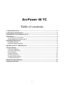
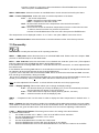
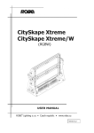
3.Description of the ArcPower 48 TC
1 - LED display
2 - Control buttons
3 - DMX Output
4 - DMX Input
5 - LED Output
6 - Fuse holder
7 - Power cord
DMX Input
Pin 1: Not connected
Pin 2: Not connected
Pin 3: Not connected
Pin 4: Not connected
Pin 5: Not connected
Pin 6: Data +
Pin 7: Data Pin 8: GND
DMX Output
Pin 1: Not connected
Pin 2: Not connected
Pin 3: Not connected
Pin 4: Not connected
Pin 5: Not connected
Pin 6: Data +
Pin 7: Data Pin 8: GND
RJ45 socket front view of the socket:
LED Output
Pin 1: Thermal sensor
Pin 2: Thermal sensor
Pin 3: Red&Green LEDs + Pin 4: Blue&White LEDs +
Pin 5: Red LEDs Pin 6: Green LEDs Pin 7: Blue LEDs Pin 8: White LEDs -
4.Installation
4.1.Connection to the mains
The ArcPower 48 TC is equipped with auto-switching power supply that automatically adjusts to any 50-60Hz
AC power source from 100-240 Volts.
Carefully prepare the end of the the supply cord and fit a suitable plug.A 3-prong grounding-type plug must be
installed following the manufacturer´s instructions.The earth has to be connected!
Cord plug connections:
Cable Pin
International
Brown
Live Light blue
Neutral
Yellow/Green
Earth
L
N
This device falls under protection class I.Therefore the ArcPower 48 TChas to be
connected to a mains socket outlet with a protective earthing connection.
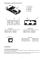
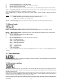
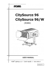
4.2.Mounting the ArcPower 48 TC
The ArcPower 48 TC should be be placed on a non-flammable flat surface in any orientation and fixed by the
two screws.There are two mounting holes of diameter 5 mm in housing of the driver. Ensure that instalation
place is enough ventilated.
Screw
Screw
Mounting hole
Flat surface
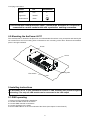
5.Installing instructions
The ArcPower 48 TC is just intended for control of LED modules with protection against
overheating ! The only one LED module can be connected to the LED output!
5.1.DMX operating
1.Unplug from the mains before installation.
2.Connect the LED module to the fixture.
3.Connect DMX controller to the fixture
4.Connect the fixture to the mains
5.Set the DMX address on the control board of the fixture (see chapter "Control board").
Warning!
Maximum total cable length between the ArcPower 48 TC and connected LED module can be 20 metres.
Multiple installation:
Connect the DMX output of the first ArcPower 48 TC with the DMX input of the next ArcPower 48. Always connect one output with the input of the next ArcPower 48 TC until all fixtures are connected.In this way,up to 32
fixtures can be chained together.
At the last ArcPower 48 TC the data link has to be terminated with a terminator. A termination plug is simply a
XLR connector with a 120 Ω resistor between pins Data (–) and Data (+).Plug terminator in the DMX output
of the last ArcPower 48.
5.2.Master-slave operating
1.Unplug from the mains before installation.
2.Connect the LED module to the drivers.
3.Connect the DMX output of the master fixture in the data-chain with the DMX input of the first slave. Always
connect output with the input of the next slave until all slaves are connected.Up to 32 fixtures can be connected
in master/slave chain
4.Insert the termination plug (with 120 Ohm) into DMX input of the master fixture and into the DMX output of
the last slave fixture in the link in order to ensure proper transmission on the data link.
5.Connect the fixtures to the mains.
6.See chapter "Stand-alone setting" in order to set the fixture as a master or slave.
6.ArcPower 48 TC - DMX protocol
version 1.0
Mode/Channel
1
2
3*
4
-
1
1
1
Value
Function
Type
of control
0-255
RED LEDs
Red LEDs saturation control (0-100%)
proportional
proportional
-
2
2
2
0-255
GREEN LEDs
Green LEDs saturation control (0-100%)
-
3
3
3
0-255
BLUE LEDs
Blue LEDs saturation control (0-100%)
proportional
-
-
4
4
0-255
WHITE LEDs
White LEDs saturation control (0-100%)
proportional
Colour macros (255 values)
No function (for DMX mode 4)
White (for DMX mode 1)
1-15
White tones (cool-->warm)
16
Blue (Blue=full, Red+Green+White=0)
17-55
Red=0, Green-->up,Blue =full, White=0
56
Light Blue (Red=0, Green=full, Blue =full, White=0)
57 - 95 Red=0, Green=full, Blue-->down, White=0
96
Green (Red=0, Green=full, Blue =0, White=0)
97 – 134 Red-->up, Green=full, Blue=0, White=0
135
Yellow-green (Red=full, Green=full, Blue=0, White=0)
136 - 174 Red=full, Green-->down, Blue=0, White=0
175
Red(Red=full, Green=0, Blue=0, White=0)
176 -214 Red=full, Green=0, Blue-->up, White=0
215
Magenta (Red=full, Green=0, Blue=full, White=0)
216 - 254 Red-->down, Green=0, Blue=full, White=0
255
Blue (Red=0, Green=0, Blue=full, White=0)
step
proportional
step
proportional
step
proportional
step
proportional
step
proportional
step
proportional
step
proportional
step
SHUTTER/STROBE
Shutter closed
Shutter open
Strobe-effect from slow to fast
Shutter open
Opening pulses in sequences slow--> fast
Closing pulses in sequences fast --> slow
Shutter open
Random strobe-effects from slow to fast
Shutter open
step
step
proportional
step
proportional
proportional
step
proportional
step
0-255
DIMMER
Dimmer intensity from 0% to 100%
proportional
0-255
DIMMER FINE
Dimmer intensity fine from low to high
proportional
0
1
-
-
5
-
-
-
6
2
-
-
7
-
-
-
8
0-31
32-63
64-95
96-127
128-143
144-159
160-191
192-223
224-255
* The mode 3 is set as default.
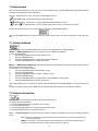
7.Control board
The control panel situated on the top cover of the ArcPower 48 TC allows DMX addressing,calling build-in
programs and setting the fixture behaviour
The four control buttons on the front have the following functions:
- ESCAPE button-leaves menu without saving changes.
- ENTER button- enters menu, confirms adjusted values and leaves menu.
- UP and
- DOWN buttons - move between menu items on the same level, sets values.
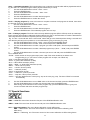
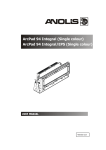
After switching the fixture on, the fixture display shows the current DMX address:
Use the UP/DOWN buttons to scroll through the various menu items. To select desired item, press the ENTER.
7.1 Fixture Address
Use this menu to set the DMX address of the fixture or set the fixture as a Master (Slave).
dM.Ad. --- DMX addressing. Select this submenu to set a DMX start address.
To set a DMX address.
1.
Use the UP/DOWN buttons to find “ A001“ menu.
2.
Press the ENTER button.
3.
Use the UP/DOWN buttons to select desired start address.
4.
Press the ENTER button to confirm the choice.
MA.SL. --- Master/slave addressing. Select this submenu to set the fixture as a master or slave. Option "d.AbL"
deactivates master/slave setting.
To set a fixture as a master or slave.
1.
Use the UP/DOWN buttons to find “A001“ menu.
2.
Press the ENTER button.
3.
Use the UP/DOWN buttons to select “ MA.SL.“ item.
4.
Press the ENTER button.
5.
Use the UP/DOWN buttons to select either master (MASt) or slave (SLA)
6.
Press the ENTER button to confirm the choice.
Note: After switching on, the ArcPower 48 TC will automatically detect whether DMX 512 data is received or
not.
If there is no data received at the DMX input, the display will start to flash with actually set address.
7.2 Fixture information
Use this menu to read useful information about the fixture status.
To display desired information.
1. Use the UP/DOWN buttons to find the “ InFo“ menu.
2. Press the ENTER button.
3. Use the UP/DOWN buttons to select the required menu item.
4. Press the ENTER button to confirm the choice.
Po.ti. --- Power On Time. Use the menu item to read the number of operation hours for each LEDs operating
mode.
totL - the function shows the total number of the operation hours since the ArcPower 48
has been fabricated.
rESEt - the function shows the number of the operation hours that the ArcPower 48 TC
has been powered on since the counter was last reset. In order to
reset this counter to 0 you have to press and hold the UP and DOWN buttons and at the
same time press the ENTER button.
DM.In.---DMX values. Select this function to read DMX values of each channel received by the fixture.
tEMP --- Fixture Temperature. Select this menu to read the temperature of the fixture:
Cur.t. --- the current temperature:
LEdS--- temperature of the LED module inside.
boAr.--- temperature of the fixture inside.
Hi.tE. - the menu item shows the max. temperatures since the ArcPower 48 TC
has been fabricated.
rSEt --- the menu item shows the maximum temperatures since the counter was last reset.
In order to reset this counter to 0 you have to press and
hold the UP and DOWN buttons and at the same time press the ENTER button.
The temperatures can be displayed in either °C or °F units - see option “tEM.U“ in the menu “Pers“. VErS. ---Software Versions. Select this function to read the software version of the fixture processor.
7.3 Personality
Use this menu to modify the ArcPower 48 TC operating behaviour.
DM.Pr. --- DMX preset. Select this menu item to set a desired DMX mode. Please refer to the chapter "DMX
protocol" for detail description of each DMX mode.
M.F.ti. --- Max. fade time. Select this menu item to set a desired max. fade time (0-25.5 sec.). This adjusted
fade time influences fade of RGBW and dimmer during DMX operation:
If time between two receiving DMX values is > than fade time set in the item M.F.ti., the entire adjusted fade
time will be used.
If time between two receiving DMX values is < than fade time set in the item M.F.ti., the adjusted fade time will
be reduced to fill entire time between the two receiving DMX values.
e.g. M.F.ti.=2sec. and fixture has received Red=0 DMX, after 5 seconds will receive Red=255 DMX. It means,
that red will go to full intensity during 2 seconds.
M.F.ti.=8 sec. and fixture has received Red=0 DMX, after 5 seconds will receive Red=255 DMX. It means, that
red will go to full intensity during 5 seconds. (Max, fade time is reduced from 8 sec. to 5 sec.).
Note: the value adjusted in the item M.F. ti. will not influence fade time set in the program steps.
DiSP. --- Display adjusting. This function allows you to change the display settings.
d.On --- this function allows you to keep the display on or to turn off automatically 2 minutes after last pressing any button on the control panel.
d.Int. --- select this function to adjust the display intensity (30-min.,100-max.).
turn --- select this function to turn the display by 180°.
tEM.U. --- Temperature Unit. Use this menu in order to display the fixture temperatures in desired units: °C
or °F.
bALA --- Balance. Use this menu item to enable (On) or disable (Off) the white balance which is set in the “White
colour balance“ menu below. If this function is set off, the ArcPower 48 TC will use maximum values (255) of
saturation for red, green and blue colour. This function has to be set on before adjusting a white balance.
C.bAL. --- White Colour Balance. The menu gives access to the setting of the white balance.
To set white colour balance.
1.
Use a DMX controller or the “ Man.C.“ menu to set all LEDs on max. saturation.
2.
Use the UP/DOWN buttons to find the “ Pers.“ menu.
3.
Press the ENTER button.
4.
Use the UP/DOWN buttons to select the “C.bAL“menu.
5.
Press the ENTER button and the “rEd“ item will appear on the display.
6.
Press the ENTER button and use the UP/DOWN buttons to set new max. value for the red LEDs.
7.
8.
9.
10.
Press the ENTER button to confirm the choice.
Use the UP/DOWN buttons to select next colour, the “GrEn“.
Repeat steps 6-7 for this channel.
Use the UP/DOWN buttons to select the last colour, the „bLuE“ and repeat steps 6-7 for this colour.
In.Po. --- Init effect positions. Use this function to set all effects to the desired positions to which they will
move after switching the fixture on (if DMX is not being received).
Note. If DMX mode 1 is selected, only values set at items “MACr” (macro) and dinr (dimmer) will be accepted.
CHAr. --- Dimmer characteristic. The option allows selection from the 2 dimming curves:
EYE - The dimming curve takes into account a gamma curve
LinE - Linear running of the dimming curve.
dF.SE. --- Default Settings .The menu item sets all fixture parameters to the default (factory) values.
7.4 Manual mode
Use this menu for control the fixture without connected DMX console.
PrE.C. --- Preset effects control. Select this menu to call up preset positions of the channel effects.
Man.C. --- Manual effect control. Select this menu to control all channels via buttons of the control board.
To control fixture channels.
1.
Use the UP/DOWN buttons to find “ Man.C“ menu.
2.
Press the ENTER button.
3.
Use the UP/DOWN buttons to select desired effect (channel).
List of control channels:
“rEd1” - red LEDs saturations
“GrE1“ - green LEDs saturations
“bLu1“ - blue LEDs saturations
“Whi1“ - white LEDs saturations
“MACr“ - colour macros
“Stro.“ - a strobe, shutter
“dimr“ - a dimmer
“F.dim” a fine dimmer
4.
Press the ENTER button and use the UP/DOWN buttons to set value , press the ENTER button to
confirm it.
7. 5 Test sequences
Use this menu to run demo-test sequences without an external controller, which will show you some possibilities of using the ArcPower 48 TC .
7.6 Stand-alone setting
The fixtures on a data link are not connected to the controller but can execute pre-set programs which can
be different for every fixture. “Stand-alone operation” can be applied to the single fixture or to multiple fixtures
operating synchronously.
Synchronous operation of multiple fixtures requires that they must be connected on a data link and one of
them is set as a master (“MASt“) and the rest as the slaves (“SLA“). Up to 32 fixtures can be connected in a
master/slave chain. Only one fixture can be set as the master.
Note: Disconnect the fixtures from the DMX controller before master/slave operating, otherwise data collisions
can occur and the fixtures will not work properly. See the chapters “Stand-alone operation“ and “ Master/slave
connection“.
10
Auto. --- Automatic playback. This function allows you to select the program which will be played after switching the fixture on. Selected program will be played continuously in a loop.
1.
Use the UP/DOWN buttons to find “ St.AL.“ menu.
2.
Press the ENTER button.
3.
Use the UP/DOWN buttons to select “ Auto“ item.
4.
Press the ENTER button.
5.
Use the UP/DOWN buttons to select desired program.
6.
Press the ENTER button to confirm the choice.
PLAY --- Playing program. By enter to this menu a complete overview of all programs is offered, from which
the program to be run can be selected.
1.
Use the UP/DOWN buttons to find “ St.AL.“ menu.
2.
Press the ENTER button.
3.
Use the UP/DOWN buttons to select desired program.
4.
Press the ENTER button. The selected program runs in a loop.
Edit --- Editing a program. The fixture offers 3 freely editable programs (EPG.1-EPG.3) each up to 68 steps.
Every program step includes a fade time-the time taken by the step´s channel status to reach the desired level
and a step time-the total time occupied by the step in the program.
E.g. If “F.tim.“=5 second and “S.tim.“=20 second, effects will go to the desired position during 5 seconds and
after that they will stay in this position for 15 seconds before going to the next prog. step
1.
Use the UP/DOWN buttons to find “ St.AL.“ menu and press the ENTER button.
2.
Use the UP/DOWN buttons to select “Edit“ menu and press the ENTER button.
3.
Use the UP/DOWN buttons to select a program you want to edit (PrG.1-PrG.3 and press ENTER
button.
4.
Use the UP/DOWN buttons to select a desired program step ("St.01" - "St.68") and press ENTER
button.
5.
Use the UP/DOWN buttons to select a channel you want to edit and press the ENTER button.
List of editable items:
“P.End” - a total number of the program steps (value 1-68). This value should be set before start
Programming (e.g. if you want to create program with 10 steps, set P.End=10).
“rEd1”- a red LEDs saturation (0-255)
“GrE1“ - a green LEDs saturation (0-255)
“bLu1“ -a blue LEDs saturation (0-255)
“Whi1“ - “Whi4“ – a white LEDs saturation (0-255)
“MACr“ - colour macros (0-255)
“Stro.“ - a strobe, shutter (0-255)
“dimr“ - a dimmer (0-255)
“F.dim”- a fine dimmer (0-255)
“F.tim.“ - a fade time, (0-25.5) seconds
“S.tim.“- step time, value (0-25.5) seconds
“COPY“. – this item duplicates the current prog. step to the next prog. step. The item “P.End” is increased
automatically.
6.
7.
8.
Use the UP/DOWN buttons to set a DMX value of the channel and then press the ENTER button.
Use the UP/DOWN buttons to select next channel and press the ENTER button.
After having set all channels in the current program step, press the MODE button to go by one
menu level back and select another program step.
7.7 Special functions
rdML --- Code.This menu item shows the first part of the RDM identification code.
rdMH --- Code. This menu item shows the second part of the RDM identification code.
AdJ --- Effect Adjustment. The menu allows calibration of each LEDs array.
dMH --- DMX Values. The menu item enables to control all LEDs before calibrating each
LEDs array.
CAL.U --- Calibrating unit. The menu serves for fine current calibration of LEDs during fixture
11
burn-in at a factory.
ibL. --- Initial blink.If this function is on, the ArcPower 48 TC makes auto-calibration (All LEDs light on 100% for
short time) after switching it on and LEDs characteristics are saved into ArcPower driver. If you do not change
load (LED modules) connected to the ArcPower , you can switch this function off, but if you change the load,
the function ones hast to run to check characteristic of all connected LEDs.
uPd.M. --- Updating mode. The menu item allows you to update software in the fixture via either serial or USB
port of PC.
The following are required in order to update software:
- PC running Windows 95/98/2000/XP or Linux
- DMX Software Uploader
- Flash cable RS232/DMX No.13050624 (if you want to use a serial port of PC)
- Robe Universal Interface (if you want to use an USB port of PC)
Note1: Software update should execute a qualified person. If you lack qualification, do not attempt the update
yourself and ask for help your ROBE distributor.
Note 2: DMX address, programs 1-3 and all items in the menu "PErS" will be set to their default values.
To update software in the fixture:
I. Installation of the DMX Software Uploader.
1. DMX Software Uploader program is available from the Anolis web site at WWW.anolis.cz.
2. Make a new directory ( e.g. Robe_Uploader) on your hard disk and download the software into it.
3. Unpack the program from the archive.
II.Fixture software updating.
1.
Determine which of your port is available on your PC and connect it:
-
with the DMX input of the fixture if you using the flash cable RS232/DMX
-
with the DMX input of the Robe Universal Interface if you using the USB cable.
Disconnect the fixture from the other fixtures in a DMX chain. Turn both the computer and the fixture on. Make
sure the lamp is switched off (only if the fixture involves a lamp).
2.
Switch the fixture to the updating mode:
1
Use the UP/DOWN buttons to find “SPEC.“ menu.
2
Press the ENTER button.
3
Use the UP/DOWN buttons to select “ uPd.“ item.
4
Press the ENTER button
5
Use the UP/DOWN buttons to select “ yES“ option
6
Press the ENTER button
Note: If you do not want to continue in software update, you have to switch off and on the fixture
to escape from this menu.
3. We recommend to cancel all running programs before start of the Software Uploader.
4. Run the Software Uploader program. Select desired COM and then click on the Connect button.
12
8.Technical Specifications:
Power supply:
Input Voltage: version:100-240 V AC, 50-60 Hz
Fuse:T 3.15A
Max.Pover Consumption:130 W
Input:
Control:DMX 512
DMX IN/OUT: RJ 45
Output:
Max.Output Voltage:48V DC
Max.Output current per colour channel : 700mA
Connector: RJ45
Max.load: 12 x 10W RGBW LED multichips
Maxi. cable length between ArcPower 48 TC and LED module: 20 metres
Control and programming:
Control panel: 4-digit LED display and four control buttons
Control: USITT DMX 512
DMX protocol modes: 4 (2,3,4, 8 control channels)
Operations modes: DMX, Stand-alone, Master/Slave
Manual control of all effects via control panel
3 user editable programs each up to 68 steps
Operating temperature:
-10°C/+40°C
Dimensions(mm):
Weight:
1.8kg
9 Replacing the fuse
1.Before replacing the fuse, unplug mains lead!
2.Unscrew the fuse holder on the rear side of the ArcPower 48 TCwith a fitting screwdriver from the housing
(anti-clockwise).
3.Remove the old fuse from the fuse holder.
4.Install the new fuse in the fuse holder.
5.Replace the fuse holder in the housing and fix it.
Specifications are subject to change without notice.
August 30, 2013
13
14