1
User instructions
ArcCove
ArcCove has a streamlined profile and various mounting options meaning greater flexibility for a wider
variety of applications. The latest LED chip technology combined with a plug and play set up process insures
incredible effects are simple to create.
1. Attention
Do not install the module near high inflammable liquids or materials
Do not allow anything to rest on the module
Do not install the module near the naked flames
Do not install the module in dirty, dusty or badly ventilated location
Avoid using the unit in locations subject to possible impacts.
Avoid looking directly into the LED light beam at close range.
Fixture must be installed by a qualified electrician in accordance with all national
and local electrical and construction codes and regulations
The product was designed for indoor use only.
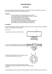
2. Mounting
Mounting of the ArcCove depends on its variant. This product is available in three design variants.
1. ArcCove - Standard - Adjustable Tilt
This variant is intended for direct mounting on a non-flammable flat surface via two mounting oval holes
of a diameter of 3.6mm in the fixture holder. The light head can be tilted in range of 180°. Secure the adjusted
position of the head via two adjusting screws, use the Allen key 1.5 (included).
2. ArcCove - Rail Mount
This variant is intended for mounting into an aluminium rail. The rail is supplied in two lengths: 1.2m and
2.4m.
Fasten the rail on a suitable surface (drill holes into rail acording screws used) and snap the ArcCove into the
rail.
3. ArcCove - Straight - Low Profile
The variant is intended for mounting into a plastic holder, this holder is removable. Fasten the holder on a nonflammable flat surface via two oval holes of a diameter of 3.6mm in the fixture holder and snap the ArcCove
into the holder.
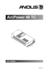
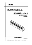
3. ArcCove connection
Keep the following rules for the ArcCoves installation (for both operating modes):
1. Maximum distance from the ArcCove DataBox to the first Arcove must not exceed 20 metres.
2. Maximum distance between two adjacent ArCoves must not exceed 20 metres.
3. Do not mistake input a output of the ArcCove.
If two adjacent AcCove modules are not placed in a line (e.g. one is turned by 90°), you have to use the patch
cable marked 90°. Max. number of connected ArcCoves depends on the length of installation and operating
mode and is mentioned in the table below.
Standard mode
Number of ArcCoves
Max. allowed distance from ArcCove DataBox to last ArcCove
(metres)
17
22
16
25
15
28
14
32
13
35
12
40
11
44
10
50
9
57
8
65
7
75
6
90
5
100
4
80
3
60
2
40
1
20
High Power mode
Number of ArcCoves
Max. allowed distance from ArcCove DataBox to last ArcCove
(metres))
8
29
7
38
6
47
5
57
4
72
3
60
2
40
1
20
4. ArcCove DataBox
Mounting
1. Unscrew two fastening screws on the top cover to get access to the display and mounting holes.
2. Fasten the bottom cover on a non-flammable flat surface via two mounting holes of a diameter of 4.5mm
in this cover.
3. Connect all needed wires (cables), check their connection and after that connect the power supply to mains.
Do not connect the ArcCove, when the ArcCove DataBox is under voltage.
4. Set desired DMX address and operating mode.
5. Screw the top cover back.
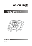
DataBox connection:
DataBox menu
The 4-digit display with four buttons serves for switching the fixture to the desired operating mode (Standard
or High Power),setting DMX address, software update and ArcCoves update etc.
Note: If DMX signal has been disconnected,
DMX address blinks.
DMX address "A001"
Press the Enter button, the display will start blinking. Set desired DMX address by means of the Up or Down
button and press the Enter button to save the address.
Menu "Info"
"dM.In" -readouts of DMX values
"VEr.L." - version of LED software in the ArcCove DataBox.
"VEr.b."- version of the ArcCove DataBox
Menu "PerS"
"dM.Pr." -DMX modes.
"Mod 1" - RGB
"Mod 2" - R1G1B1,R2G2B2..... (default)
"M.F.Ti." - Max. Fade time (0-25.5sec.). This adjusted fade time influences fade of Red, Green
and Blue colour during DMX operation as follows:
1. If time between two receiving DMX values is > than fade time set in the item “M.F.Ti.“, the entire
adjusted fade time will be used.
2. If time between two receiving DMX values is < than fade time set in the item “M.F.Ti.“, the adjusted fade time will be reduced to fill entire time between the two receiving DMX values.
E.g. “M.F.Ti.“=2 sec. and a fixture has received Red=0 DMX, after 5 seconds will receive
Red=255 DMX. It means, that red will go to full intensity during 2 seconds.
“M Ftime“=8 sec. and fixture has received Red=0 DMX, after 5 seconds will receive Red=255 DMX.
It means, that red will go to full intensity during 5 seconds. (Max, Fade time is reduced from 8 sec.
to 5 sec.).
"LoAd" - operating mode.
"StAn" - Standard operating mode (max. 17 units per power supply)
"HiGh" - High Power operating mode (max. 8 units per power supply)
"In.Po" - Initial position (LEDs saturation after switching the ArcCove DataBox on without DMX connected). For SW variant
"rEd" - red LEDs saturation
"VArM" - warm white LEDs saturation
"GrEn" -green LEDs saturation
"BluE" - blue LEDs saturation
"SAVE" - saving set values
"dF.SE" - default setting
"COOL" -cool white LEDs saturation
Menu "Man.C" - manual control of LED colours.
"rEd" - red LEDs saturation
"GrEn" -green LEDs saturation
"BluE" - blue LEDs saturation
For SW variant
"VArM" - warm white LEDs saturation
"COOL" -cool white LEDs saturation
Menu "St.AL." - Stand Alone setting.
"Auto" - this function allows you to select a program (Prg.1, Prg.2) which will be played
automatically after switching the fixture on. Selected program will be played continuously in
a loop. To disable this function, set OFF.
"PLAy" - this function allows to run one of the following programs:
"Prg.1" - changing colours in connected ArcCoves at the same time.
"Prg.2" - gradual changing colours in connected ArcCoves (colour chase)
"S.tiM." - a step time (0.1-25.5 sec.). This item controls "speed" of the chase ("Prg.2").
"F.tiM." - a fade time (0.1-25.5 sec.)
"M.Mod." - a number of conected ArcCoves (1-17). This number has to respond to
the number of connected ArcCoves and has to be set correctly - also check
setting of the item "LoAd".
If the "M.Mod." < than number of connected ArcCoves, not all ArcCoves will light.
If the "M.Mod." > than number of connected ArcCoves, a pause may appear in
a program running.
Menu "SPEC" - special functions
"uPd.L" - update of connected ArcCoves
"uPd.b" - update of the ArcCove DataBox
To update software in the ArcCove DataBox - "uPd.P"
The following are required in order to update software:
Notebook running Windows 95/98/2000/XP/7/8 or Linux
Robe Universal Interface or Robe Universal Interface WTX
Necessary cables (5-pin DMX cable,USB cable)
Note: The software update should execute a qualified person. If you lack qualification, do not attempt the update
yourself and ask for help your Anolis distributor.
1. Download software from from Anolis web site at WWW.anolis.cz.
This software has name DSU_ArcCove_number of version.
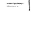
2. Disconnect power supply from the ArcCove DataBox and connect the Robe Universal Interface to the DMX
input of the ArcCove DataBox as shown on the picture below. If another ArcCove DataBox is connected to
DMX output of this DataBox, it can stay connected.
3. Connect the ArcCove DataBox to the power and select "uPd.P" from the menu "SPEC", after that "YES" and
the display reduces light intensity - device is in the update mode.
4. Unpack and run the update program. Select "Robe Universal Interface" from the option "COM Ports" and
then click on the "Connect" button.
If the connection is OK, click on the "Start Uploading" button to start uploading. It can take a few minutes
to perform software update. If the option "Incremental Update" is not checked, all processors will be updated
(including processors with the same software version).
Avoid interrupting the process. Update status is being displayed in the Info Box window.
When the update is finished, the line with the text “The fixture is successfully updated" will appear in this window
and the fixture´s display will show current DMX address. After the software update of the ArcCove DataBox
you can also perform update of all connected ArcCoves as stated below.
Note: In the case of an interruption of the upload process (e.g. power cut), the DataBox keeps the updating
mode and you have to repeat the software update again.
To update software in ArcCoves "uPd.L"
Note: the current software version of the ArcCove DataBox from the Anolis website has to be loaded into the
the ArcCove DataBox. See the article above.
Select "uPd.L" from the menu "SPEC", select "YES" and update of ArcCoves will start, the display will show
progress of the ArcCoves update in % F001, F002..... F100. When updating is finished, the current DMX address will be shown at the display.
5. ArcCove DataBox - DMX chart (RGB variant)
Version 1.1
Mode 1/Channel
Mode 2/Channel
(default)
1
1
2
3
1
2
2
3
4
5
3
6
1
7
2
3
1
2
3
8
9
10
11
12
Value
Function
Type of control
0-255
ArCove 1 - Red pixel 1
Red LED saturation control (0-100%)
proportional
0-255
ArCove 1 - Green pixel 1
Green LED saturation control (0-100%)
proportional
0-255
ArCove 1 - Blue pixel 1
Blue LED saturation control (0-100%)
proportional
0-255
ArCove 1 - Red pixel 2
Red LED saturation control (0-100%)
proportional
0-255
ArCove 1 - Green pixel 2
Green LED saturation control (0-100%)
proportional
0-255
ArCove 1 - Blue pixel 2
Blue LED saturation control (0-100%)
proportional
0-255
ArCove 2 - Red pixel 1
Red LED saturation control (0-100%)
proportional
0-255
ArCove 2 - Green pixel 1
Green LED saturation control (0-100%)
proportional
0-255
ArCove 2 - Blue pixel 1
Blue LED saturation control (0-100%)
proportional
0-255
ArCove 2 - Red pixel 2
Red LED saturation control (0-100%)
proportional
0-255
ArCove 2 - Green pixel 2
Green LED saturation control (0-100%)
proportional
0-255
ArCove 2 - Blue pixel 2
Blue LED saturation control (0-100%)
proportional
:
:
1
55
2
56
3
57
1
58
2
59
3
60
0-255
ArCove 10 - Red pixel 1
Red LED saturation control (0-100%)
proportional
0-255
ArCove 10 - Green pixel 1
Green LED saturation control (0-100%)
proportional
0-255
ArCove 10 - Blue pixel 1
Blue LED saturation control (0-100%)
proportional
0-255
ArCove 10 - Red pixel 2
Red LED saturation control (0-100%)
proportional
0-255
ArCove 10 - Green pixel 2
Green LED saturation control (0-100%)
proportional
0-255
ArCove 10 - Blue pixel 2
Blue LED saturation control (0-100%)
proportional
:
:
1
2
3
1
2
3
97
98
99
100
101
102
0-255
ArCove 17 - Red pixel 1
Red LED saturation control (0-100%)
proportional
0-255
ArCove 17 - Green pixel 1
Green LED saturation control (0-100%)
proportional
0-255
ArCove 17 - Blue pixel 1
Blue LED saturation control (0-100%)
proportional
0-255
ArCove 17 - Red pixel 2
Red LED saturation control (0-100%)
proportional
0-255
ArCove 17 - Green pixel 2
Green LED saturation control (0-100%)
proportional
0-255
ArCove 17 - Blue pixel 2
Blue LED saturation control (0-100%)
proportional
ArcCove DataBox - DMX chart (SW variant)
Version 1.1
Mode 1/Channel
Mode 2/Channel
(default)
1
1
2
1
2
3
2
4
1
5
2
6
1
7
2
8
Value
Function
Type of control
0-255
ArCove 1 - WW pixel 1
Warm white LED saturation control (0-100%)
proportional
0-255
ArCove 1 - CW pixel 1
Cool white LED saturation control (0-100%)
proportional
0-255
ArCove 1 - WW pixel 2
Warm white LED saturation control (0-100%)
proportional
0-255
ArCove 1 - CW pixel 2
Cool white LED saturation control (0-100%)
proportional
0-255
ArCove 2 - WW pixel 1
Warm white LED saturation control (0-100%)
proportional
0-255
ArCove 2 - CW pixel 1
Cool white LED saturation control (0-100%)
proportional
0-255
ArCove 2 - WW pixel 2
Warm white LED saturation control (0-100%)
proportional
0-255
ArCove 2 - CW pixel 2
Cool white LED saturation control (0-100%)
proportional
:
:
1
2
1
2
37
38
39
40
0-255
ArCove 10 - WW pixel 1
Warm white LED saturation control (0-100%)
proportional
0-255
ArCove 10 - CW pixel 1
Cool white LED saturation control (0-100%)
proportional
0-255
ArCove 10 - WW pixel 2
Warm white LED saturation control (0-100%)
proportional
0-255
ArCove 10 - CW pixel 2
Cool white LED saturation control (0-100%)
proportional
:
:
1
65
2
66
1
67
2
68
0-255
ArCove 17 - WW pixel 1
Warm white LED saturation control (0-100%)
proportional
0-255
ArCove 17 - CW pixel 1
Cool white LED saturation control (0-100%)
proportional
0-255
ArCove 17 - WW pixel 2
Warm white LED saturation control (0-100%)
proportional
0-255
ArCove 17 - CW pixel 2
Cool white LED saturation control (0-100%)
proportional
6. Power supply PLN-100-24 (Anolis registration name is the ArcCove Power MW)
The power supply PLN-100-24 serves for supply of the ArcCove DataBox which is a control unit for ArcCoves.
The power supply is intended for fixed installation only.
Mounting:
1. Fasten the power supply PLN-100-24 on a non-flammable flat surface via two mounting slots of a diameter
of 5mm in the housing.
2. Connect output wires ( red wire= + 24V, black wire= -) to the ArcCove DataBox.
3. After checking the rest of connections (ArcCove DataBox - first ArcCove, ArcCoves-ArcCoves) connect
the power supply PLN-100-24 to mains (brown wire= live, .blue wire= neutral, green/yellow wire = earth).
7. Error states
Description
Reason
The ArcCove blinks in a low intensity of red colour
The ArcCove´s input and output are replaced.
Connect this unit correctly.
The last ArcCoves do not lit
Max. number of ArcCoves per one power supply is
exceeded. Disconnect redundant ArCoves.
8. ArcCove installation items overview
The customer has to specify needed items (and their quantity).
Each ArcCove Set includes: 17x ArcCove, 17x cable patch ArcCove 10 cm, 1x ArcCove Power MW, 1x ArcCove DataBox
ArcCoves
ArcCove,RGB, Standard, Adjustable Tilt (No. 006 2591 - 17 pcs/box)
ArcCove, SmartWhite, Standard - is available on request
ArcCove , RGB, Straight, Low Profile (No. 1006 2592 - 17 pcs/box )
ArcCove , SmartWhite, Straight, Low Profile - is available on request
ArcCove , RGB, Rail mount (No. 1006 2593 - 17 pcs/box)
ArcCove , SmartWhite, Rail mount- is available on request)
Devices for control of the ArcCoves. ArcCove DataBox (No. 10062515)
ArcCove DataBox SmartWhite (No. 1006 2574)
Wireless DMX variants:
ArcCove DataBox/W (No. 10062532)
ArcCove DataBox SmartWhite/W (No. 1006 2575)
Note: One ArcCove DataBox can be used for 17 (8) ArcCoves
according to the operating mode. Each set of the ArcCove modules (17
units in a box) includes corresponding ArcCove DataBox.
Power supply for ArCoves.
Power supply PLN-100-24 alias ArcCove Power MW (No. 10062517)
Note: One power supply PLN-100-24can be used for 17 (8) ArcCoves
according to the operating mode. Each set of the ArcCove modules (17
units in a box) includes one power supply
Connecting cable between the ArcCove DataBox and
the first ArcCove. (Black covers of connectors)
Cable connecting ArcCove 1m (No. 13071995)
Cable connecting ArcCove 2m (No. 13071996)
Cable connecting ArcCove 5m (No. 13071997)
Cable connecting ArcCove 10m (No. 13071998)
Connecting cables between ArcCoves.*
Cable patch ArcCove 10 cm (No. 13051982)
Cable patch ArcCove 15 cm (No. 13051989)
Cable patch ArcCove 9.5 cm, 90° (No. 1305 2020)
Cable patch ArcCove 12 cm, 90° (No. 13051990)
Cable patch ArcCove 15 cm, 90° (No. 13051991)
Cable patch ArcCove 30 cm, 90° (No. 13051994)
Note: each set of the ArcCove modules (17 units in a box) includes 17
pieces of the Cable patch ArcCove 10 cm (No. 13051982)
Mounting rail (only for the ArcCove, Rail Mount).
Mounting Rail ArcCove 1.2m (No. 19030286)
Mounting Rail ArcCove 2.4m (No. 19030267)
* Proper cable length depends on the position of ArcCoves. For custom version of the connecting cables the
distance between ArcCoves has to be specified as shown at next page.
10
11
9. Technical specifications
ArcCove
Light source: Input voltage : Maximum power consumption: Typical Lumen maintenance: Cooling system: Ambient operating temp.range:
Control electronics:
Control channels:
Maximum units per
one power supply: Design:
Beam angle:
Weight:
Connection:
Cable:
ArcCove DataBox
Control:
Connection:
Weight:
10 x 1W RGB multichip per fixture (group of five multichips
creates one pixel)
24 V DC
5W (Standard Mode), 10.8 W (High Power Mode) per fixture
50000+ hours L50@ 50°C
convection
-20°C/+40°C
Internal chip protection against overheating
Repeater included
6 per fixture (RGB,RGB)
17 (Standard Mode), 8 (High Power Mode)
Housing &Base: ABS
Transparent cover: polycarbonate
110° (at half beam)
0.16 kg
Integral In/Out connectors
5 wire flat cable Ribbon UL2468 AWG 18/5C
4-digit LED display & 4 buttons
DMX&power: connection block
ArcCove: integral connector
0.15kg Power supply PLN-100-24 (alias ArcCove Power MW)
Input voltage:
100-240V AC; 50/60Hz
Output voltage:
24V DC
Rated current:
4A
Rated output power:
96W
Power factor:
>95
Protection:
Short circuit/ Overload / Over voltage / Over temperature
Cooling:
by free air convection
Connection:
Input - 3-wire cable 18AWG 3C, length=310mm
Output - 2-wire cable 18AWG 2C, length=310mm
Weight:
0.52kg
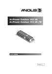
10. Dimensions (mm)
ArcCove, Standard, Adjustable Tilt
12
ArcCove, Straight, Low Profile
ArcCove, Rail Mount
13
ArcCove DataBox
Power supply PLN-100-24 (alias ArcCove Power MW)
Version 1.9
December 7, 2015
Specifications are subject to change without notice.
14