1
Analysis of footings to DIN 4017, DIN 4019,
DIN 1054 and EC 7
GGU-FOOTING
VERSION 8
Last revision:
April 2015
Prof. Dr. Johann Buß
Copyright:
Technical implementation and sales: Civilserve GmbH, Steinfeld
Contents:
1 Preface .................................................................................................................................. 5
2 Licence protection and installation .................................................................................... 5
3 Language selection............................................................................................................... 6
4 Starting the program ........................................................................................................... 6
5 Short description and worked examples............................................................................ 7
5.1 Output sheet design .......................................................................................................... 7
5.1.1 Generate result graphics........................................................................................... 7
5.1.2 Move graphic elements............................................................................................ 9
5.1.3 Edit and turn off graphic elements........................................................................... 9
5.1.4 Edit page size and margins .................................................................................... 11
5.2 Example 1: Multiple footings......................................................................................... 12
5.2.1 Enter analysis options (Example 1) ....................................................................... 12
5.2.2 Enter system parameters (Example 1) ................................................................... 13
5.2.3 Define footings (Example 1).................................................................................. 16
5.2.4 Define soils (Example 1) ....................................................................................... 17
5.2.5 Select the limiting depth (Example 1).................................................................... 18
5.2.6 Analyse system (Example 1) ................................................................................. 18
5.3 Example 2: Single rectangular footing........................................................................... 19
5.3.1 Enter analysis options (Example 2) ....................................................................... 19
5.3.2 Enter system parameters (Example 2) ................................................................... 20
5.3.3 Define footing (Example 2) ................................................................................... 21
5.3.4 Define soils (Example 2) ....................................................................................... 22
5.3.5 Analyse system (Example 2) ................................................................................. 22
5.3.6 Represent results in the plan view of footing (Example 2).................................... 23
5.3.7 Consider depth coefficients (Example 2)............................................................... 25
5.3.8 Represent results in the pad footing legend (Example 2) ...................................... 26
5.4 Example 3: Single circular footing (EC 7)..................................................................... 27
5.4.1 Enter analysis options (Example 3) ....................................................................... 27
5.4.2 Enter system parameters (Example 3) ................................................................... 28
5.4.3 Define footing (Example 3) ................................................................................... 29
5.4.4 Define soils (Example 3) ....................................................................................... 30
5.4.5 Analyse system (Example 3) ................................................................................. 31
5.4.6 Represent results in the plan view of footing (Example 2).................................... 32
6 Theoretical principles ........................................................................................................ 34
6.1 Analysis of bearing capacity safety................................................................................ 34
6.2 Theoretical principles circle/annulus.............................................................................. 36
6.3 Determining the mean governing soil properties ........................................................... 37
6.4 Differences between DIN 1054 (old) and DIN 1054:2005/EC 7................................... 38
6.5 Settlement analysis ......................................................................................................... 42
GGU-FOOTING User Manual
Page 2 of 81
April 2015
7 Description of menu items................................................................................................. 43
7.1 File menu........................................................................................................................ 43
7.1.1 "New" menu item................................................................................................... 43
7.1.2 "Load" menu item.................................................................................................. 44
7.1.3 "Save" menu item .................................................................................................. 44
7.1.4 "Save as" menu item .............................................................................................. 44
7.1.5 "Print output table" menu item............................................................................... 45
7.1.5.1 Output as graphics......................................................................................... 45
7.1.5.2 Output as ASCII ............................................................................................ 47
7.1.6 "Printer preferences" menu item............................................................................ 48
7.1.7 "Print and export" menu item ................................................................................ 48
7.1.8 "Batch print" menu item ........................................................................................ 50
7.1.9 "Exit" menu item.................................................................................................... 50
7.1.10 "1, 2, 3, 4" menu items........................................................................................... 50
7.2 Edit menu ....................................................................................................................... 51
7.2.1 "Analysis options" menu item................................................................................ 51
7.2.2 "Project identification" menu item......................................................................... 51
7.2.3 "System parameters" menu item ............................................................................ 52
7.2.4 "Footing details" menu item .................................................................................. 53
7.2.5 "Soils" menu item .................................................................................................. 54
7.2.6 "Limiting depth" menu item .................................................................................. 54
7.2.7 "Line loads" menu item ......................................................................................... 55
7.2.8 "Berms" menu item................................................................................................ 56
7.2.9 "Partial safety factors" menu item ......................................................................... 57
7.3 System menu .................................................................................................................. 58
7.3.1 "Analyse" menu item ............................................................................................. 58
7.3.2 "Optimise footing width" menu item ..................................................................... 58
7.4 Output preferences menu ............................................................................................... 59
7.4.1 "Footing analysis diagram" menu item.................................................................. 59
7.4.2 "Footing plan" menu item...................................................................................... 61
7.4.3 "Soil properties" menu item................................................................................... 62
7.4.4 "System presentation" menu item .......................................................................... 63
7.4.5 "General legend" menu item.................................................................................. 64
7.4.6 "Output table" menu item ...................................................................................... 65
7.4.7 "Pad footing" menu item........................................................................................ 66
7.4.8 "Stress influence diagram" menu item................................................................... 67
7.4.9 "Line loads" menu item ......................................................................................... 68
7.4.10 "Reset all graphics to defaults" menu item ............................................................ 68
7.4.11 "Fixed scales" menu item....................................................................................... 69
7.4.12 "Page size and margins" menu item....................................................................... 69
7.4.13 "Move objects" menu item..................................................................................... 70
7.5 Graphics preferences menu ............................................................................................ 70
7.5.1 "Refresh and zoom" menu item ............................................................................. 70
7.5.2 "Fill colours" menu item........................................................................................ 71
7.5.3 "Zoom info" menu item ......................................................................................... 71
7.5.4 "Legend font selection" menu item........................................................................ 71
GGU-FOOTING User Manual
Page 3 of 81
April 2015
7.5.5 "Margins and borders" menu item ......................................................................... 71
7.5.6 "Pen colour and width" menu item ........................................................................ 72
7.5.7 "Mini-CAD toolbar" menu item ............................................................................ 72
7.5.8 "Toolbar preferences" menu item .......................................................................... 73
7.5.9 "Load graphics preferences" menu item ................................................................ 74
7.5.10 "Save graphics preferences" menu item................................................................. 74
7.6 ? menu ............................................................................................................................ 75
7.6.1 "Copyright" menu item .......................................................................................... 75
7.6.2 "Help" menu item .................................................................................................. 75
7.6.3 "GGU on the web" menu item ............................................................................... 75
7.6.4 "GGU support" menu item..................................................................................... 75
7.6.5 "What's new?" menu item...................................................................................... 75
7.6.6 "Language preferences" menu item ....................................................................... 75
8 Tips and tricks.................................................................................................................... 76
8.1 Keyboard and mouse...................................................................................................... 76
8.2 Function keys ................................................................................................................. 76
8.3 "Copy/print area" icon.................................................................................................... 77
9 Index.................................................................................................................................... 78
List of figures:
Figure 1 Result screen .....................................................................................................................8
Figure 2 Equivalent area for circle (Leibniz University, Hannover).............................................36
Figure 3 Logarithmic spiral...........................................................................................................37
Figure 4 Line load..........................................................................................................................55
Figure 5 Berms...............................................................................................................................56
GGU-FOOTING User Manual
Page 4 of 81
April 2015
1 Preface
The GGU-FOOTING program allows the analysis of bearing capacity according to DIN 4017
and of settlement according to DIN 4019. Both the global safety factors according to DIN 1054
(old) and the partial safety factors according to DIN 1054:2005 or EC 7 may be taken into consideration. In addition to the standard DIN 4017 methods, the methods after Terzaghi, Meyerhoff,
Hansen and Vesic that are well known from many literature references may also be adopted.
The program provides two different types of analysis:
Mode 1: "Multiple footings"
Multiple footings of a single type (pad or strip footing), which only vary in their width, are
analysed. In this mode it is possible to generate footing analysis diagrams from which the
bearing pressure (EC7), the acceptable bearing pressure (DIN 1054:2005) or the allowable
footing pressure (DIN 1054 old) can be read off as a function of the footing width, together
with the corresponding settlement.
Mode 2: "Pad footing"
A pad footing is analysed. It is possible to select between either a rectangular, or a circular or annular footing. Analysis of the torsional stiffness, which can be determined using
this mode for circular or annular footings, is often required for wind energy converters.
The program system allows comfortable data input. Graphic output supports the true-type fonts
supplied with WINDOWS, so that excellent layout is guaranteed. Colour output and any graphics
(e.g. files in formats BMP, JPG, PSP, TIF, etc.) are supported. DXF files can also be imported by
means of the integrated Mini-CAD module (see the Mini-CAD manual).
The program is used almost daily in the course of GGU engineering work. Further to this, the
program has been thoroughly tested on numerous examples from the literature and in engineering
practice. No faults have been found. Nevertheless, liability for completeness and correctness of the
program and the manual, and for any damage resulting from incompleteness or incorrectness,
cannot be accepted.
2 Licence protection and installation
In order to guarantee a high degree of quality, a hardware-based copy protection system is used
for the GGU-FOOTING program.
The GGU software protected by the CodeMeter copy protection system is only available in
conjunction with the CodeMeter stick copy protection component (hardware for connection to the
PC, "CM stick"). Because of the way the system is configured, the protected software can only be
operated with the corresponding CM stick. This creates a fixed link between the software licence
and the CM stick copy protection hardware; the licence as such is thus represented by the CM
stick. The correct Runtime Kit for the CodeMeter stick must be installed on your PC.
Upon start-up and during running, the GGU-FOOTING program checks that a CM stick is
connected. If it has been removed, the program can no longer be executed.
For installation of GGU software and the CodeMeter software please refer to the information in
the Installation notes for GGU Software International, which are supplied with the program.
GGU-FOOTING User Manual
Page 5 of 81
April 2015
3 Language selection
GGU-FOOTING is a multilingual program. The program always starts with the language setting
applicable when it was last ended.
The language preferences can be changed at any time in the "?" menu, using the menu item "Language preferences" (in German: "Spracheinstellung", in Spanish: "Configuración de idioma").
4 Starting the program
After starting the program, you will see two menus at the top of the window:
File
?
By going to the "File" menu, a previously analysed system can be loaded by means of the "Load"
menu item, or a new one created using "New". After clicking the "New" menu item a dialog box
opens for specifying general preferences for your new system (see Section 7.1.1). After leaving
the box you then see six menus in the menu bar:
File
Edit
System
Output preferences
Graphics preferences
?
After clicking one of these menus, the menu items roll down, allowing you access to all program
functions.
The program works on the principle of What you see is what you get. This means that the screen
presentation represents, overall, what you will see on your printer. In the last consequence, this
would mean that the screen presentation would have to be refreshed after every alteration you
make. For reasons of efficiency and as this can take several seconds for complex screen contents,
the GGU-FOOTING screen is not refreshed after every alteration.
If you would like to refresh the screen contents, press either [F2] or [Esc]. The [Esc] key additionally sets the screen presentation back to your current zoom, which has the default value 1.0,
corresponding to an A3 format sheet.
GGU-FOOTING User Manual
Page 6 of 81
April 2015
5 Short description and worked examples
5.1
5.1.1
Output sheet design
Generate result graphics
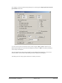
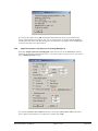
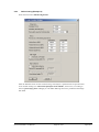
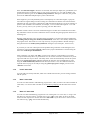
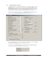
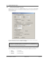
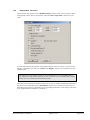
After starting the program the logo is at first displayed. Select the menu item "File/New". Then,
the following dialog box is shown.
f
Keep the default settings. You may enter a project identification (e.g. "My first attempt"). After
confirming with "OK" you will see a dialog box, in which you can select the load case to be analysed. The safety factors corresponding to the selected load case are automatically used in the
system data.
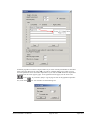
Leave the dialog box clicking on the "DS-P" button and then select the "System/Analyse" menu
item. First, an info box concerning the punching verification appears. Then the analysis results
with all graphics for the values given by the program are shown on the screen.
GGU-FOOTING User Manual
Page 7 of 81
April 2015
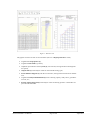
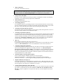
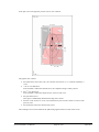
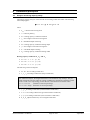
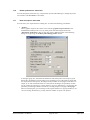
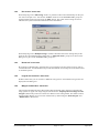
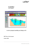
Figure 1 Result screen
The graphic consists of a total of seven elements (also see "Output preferences" menu).
Legend with soil properties (1);
Legend with line loads (if present);
Graphical representation of the system (2) (soil structure, footing and associated logarithmic spiral);
Output table (3) with analysis results for the selected footing types;
Stress influence diagram (4) with the soil structure, footing and associated stress distribution;
Legend with analysis fundamentals (5) such as bearing capacity safety factor, groundwater level, etc.;
Footing analysis diagram (6) with analysis results for bearing pressure or allowable soil
pressure and settlements.
GGU-FOOTING User Manual
Page 8 of 81
April 2015
5.1.2
Move graphic elements
All seven elements can be arranged at will. Select the "Move objects" menu item from the "Output preferences" menu. Confirm the info box with "OK". Move the mouse over the object to be
moved, press the left mouse button and keep it pressed whilst moving the object. After releasing
the mouse button the object is shown at its new position.
The size of some objects can also be altered. To alter the size of an object, move the mouse to the
top or right-hand edge of the object in question and move the edge with the left mouse button
pressed. If you are within the boundaries of a graphic element, the mouse pointer changes to a
cross with double arrows pointing left-right and up-down. If the mouse pointer is at the top or
right-hand edge of a resizable element, the mouse pointer changes to a simple double-arrow,
pointing either left-right or up-down. To carry out further alterations, the menu item must be reactivated after each movement.
You can activate this program function without the info box by pressing the [F11] function
key.
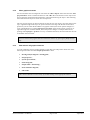
5.1.3
Edit and turn off graphic elements
You can completely remove graphic elements or alter their size and position. Select one of the
following menu items from the "Output preferences" menu:
"Footing analysis diagram"/"Footing plan";
"Soil properties";
"System presentation";
"General legend";
"Output table"/"Pad footing";
"Stress influence diagram";
"Line loads".
This can be achieved even more easily by double-clicking in the appropriate element.
GGU-FOOTING User Manual
Page 9 of 81
April 2015
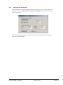
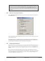
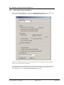
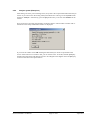
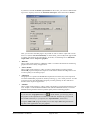
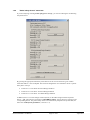
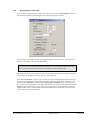
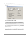
For example, you will see the following dialog box by selecting the "Output preferences/System
presentation" menu item:
You can switch off the representation of the system using the "Show system" check box. Just
deactivate the check box. If you leave the dialog box by means of "OK", the system presentation
will no longer be displayed.
The size and position of the system presentation can be defined in the dialog box. You can also
decide whether certain elements and labelling should be displayed in the diagram.
The dialog boxes for other graphic elements are similarly structured.
GGU-FOOTING User Manual
Page 10 of 81
April 2015
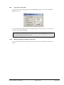
5.1.4
Edit page size and margins
The program uses A3 format as the default drawing size. However, the size can be edited to suit
your needs. Go to the "Output preferences/Page size and margins" menu item and enter your
personal page format.
Page margins defines the position of a frame as a distance to the cutting border. This frame encloses the subsequent diagram.
GGU-FOOTING User Manual
Page 11 of 81
April 2015
5.2
5.2.1
Example 1: Multiple footings
Enter analysis options (Example 1)
Select the menu item "File/New". When the program is started the check boxes "Partial safety
factor concept (EC 7)" and "Multiple footings" are already activated. Alternatively, the standard
and the analysis mode can be selected by going to the menu item "Edit/Analysis options".
After confirming with "OK" you can select the load case. Choose "DS-P". The partial safety factors are used in the system data.
You can enter a project identification for the current problem, which is subsequently shown in the
General legend. A project identification is entered when selecting the type of system in the above
dialog box or via the "Edit/Project identification" menu item.
GGU-FOOTING User Manual
Page 12 of 81
April 2015
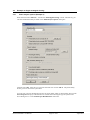
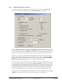
5.2.2
Enter system parameters (Example 1)
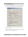
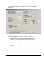
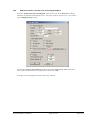
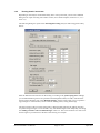
The appropriate partial safety factors have already been entered into the "Edit/System parameters" menu item. The quantities described below can be entered or edited. Use the default values
for the example.
"Partial FOS (bearing capacity/permanent actions/changeable actions):"/"Bearing capacity FOS [-]:"
safety factor according to DIN 4017
"Groundwater table [m]:"
measured from ground level in m
"Footing base [m]:"
measured from ground level in m
"Slope inclination [°]:"
positive values only (= falling slope)
The older version of DIN 4017 did not envisage taking slope inclination into consideration. If you are not investigating slopes in accordance with DIN 4017:2006 (the appropriate check box is deactivated, see below), you should therefore examine the approach
for your problem used in "Theoretical principles" as a matter of urgency.
Input of slope inclination here does not represent a substitute for slope stability analysis
according to DIN 4084 !!!!. The program assumes that the slope is stable.
GGU-FOOTING User Manual
Page 13 of 81
April 2015
"Berm width [m]:"
measured in m beside the footing
The current issue of DIN 4017 does not envisage consideration of berms. You should
therefore examine the "Theoretical principles" for an approach to your problem.
"Slope to DIN 4017:2006"
Previous versions of DIN 4017 did not provide for consideration of slopes. We therefore
installed or own model for taking slopes into consideration.
"Base inclination [°]:"
inclination of the footing base in [°]
"Preloading [kN/m²]:"
For settlement analyses, a preloading in kN/m² can be subtracted from the current footing
pressure. Settlement analysis will then be performed with the reduced values. The overburden stress is also reduced by this amount when calculating the limiting depth.
"Surcharge (bearing capacity) [kN/m²]:"
The bearing capacity surcharge defines a stress on the ground, which generates a stress on
the failure body in addition to the embedment depth.
"Surcharge (settlements) [kN/m²]:"
According to DIN 4019, settlement analysis can be terminated at a depth (limiting depth) in
which the stress from soil self-weight and ground surcharges is greater than 20 % of the
stresses caused by the footing. You can enter the ground surcharge for this limiting depth
calculation in "Surcharge (settlement)". Input is only of importance if you calculate the
limiting depth as a function of the surcharge stress (see also Section 5.2.5).
"H/V [-]:"
Ratio of the horizontal force H to the vertical force V
In the bearing capacity equation in DIN 4017, a horizontal force can be taken into consideration. In GGU-FOOTING this force can be defined as a ratio to the vertical force.
"Calculate using depth coefficients"
In the bearing capacity equations in DIN 4017, the effects of the shear strength of the soil
above the footing base are neglected. According to Section 6.1 ("Theoretical principles/Analysis of bearing capacity failure"), this influence can be considered by applying
the depth coefficients dc and dd. Four different procedures are available, which can be selected via the dropdown menu. The depth coefficient equations can be found in the above
mentioned Section 6.1 of this manual.
"Friction angle for bearing capacity failure"
Three of the four depth coefficient equations use a friction angle:
Check box deactivated ==> mean friction angle at footing base will be adopted.
Check box activated ==> friction angle for bearing capacity analysis will be adopted.
"Depth coefficients for slopes too"
If the slope inclination ≠ 0, the parameters dc and dd are set to "1.0" if the check box is deactivated. If the check box is activated, the influence of the shear strength of the soil above
the footing base is also taken into consideration in a slope.
"Verify bearing capacity for short side only"
The program verifies the bearing capacity safety for the short and the long sides of the footing. In rare, exceptional cases (see the included file "DIN 4017 new Example 6 a flexible.gdg") it may be expedient to verify the short side only. You should then activate this
check box.
GGU-FOOTING User Manual
Page 14 of 81
April 2015
"Limit soil pressure" group box
For predefined footing types, the program calculates the allowable soil pressure as a function of the footing width. If footing pressures are determined, which are too high for your
taste, in particular for large footing widths, possibly due to excessively high settlement or
for simple safety reasons (the structural engineer always computes with the allowable values provided by you), you can limit the allowable footing pressure to a defined level. Activate the "Apply" check box and enter the required maximum value.
"5° condition" group box
According to DIN 4017 the soil properties can be averaged out for stratified ground. The
condition for this is that the averaged friction angle demonstrates a maximum deviation of
5° to the true friction angles. The program checks this condition. If it is not adhered to, a
warning signal is given after the analysis. Alternatively, you can have the program reduce
all friction angles in stages, which lie above the average value. The size of the reduction is
specified with "Decrement [°]". Small decrement values mean long computation times
with high precision. A reduction only takes place if the "Check and correct" check box is
activated.
"Ratio changeable/total loads [-]:" group box
The failure stress is first divided by the bearing capacity partial safety factor. This gives the
bearing capacity stress. A further reduction by the partial safety factors for actions is necessary for calculation of an allowable footing pressure or acceptable bearing pressure. In load
case 1, e.g., a partial safety factor of gam(G) = 1.35 for permanent loads and one of gam(Q)
= 1.50 for changeable loads is demanded. From a ratio of 0.40, for example, a total partial
factor results from:
Ratio · 1.50 + (1.0 - ratio) · 1.35 = 1.410
"Punching analysis" group box
Punching analysis can be activated here. DIN 4017:2006 describes a new punching analysis method. To use this new analysis method the "Punching analysis using new method
(recommended)" check box in the 'File/New' dialog box is activated by default when the
program starts. The punching analysis equations given in DIN 4017:2006 differentiate between flexible and rigid footings. Accordingly you will activate or deactivate the Flexible
footing" check box.
GGU-FOOTING User Manual
Page 15 of 81
April 2015
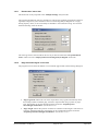
5.2.3
Define footings (Example 1)
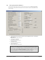
In the "Edit/Footing details" menu item you define the size and shape of the footing.
The "Start width", the "End width" and the "Delta width" are entered in this box. You thus
define the width range to be investigated. Thus, using the example given above, the widths 0.4,
0.5, 0.6, ... to 2.0 m will be investigated.
You must also enter whether a strip or a pad footing is to be analysed. The example above would
analyse a strip footing. When analysing a strip footing, enter the strip length applicable to all
widths. This strip length is required for the subsequent settlement analysis.
To analyse a pad footing you define whether a constant length/width ratio (a/b) or a constant footing length (a) is analysed. If you have activated a pad footing with constant length a, you may
find, for an appropriate start width, that a < b. In this case a warning message is issued to inform
you that a = b.
GGU-FOOTING User Manual
Page 16 of 81
April 2015
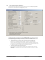
5.2.4
Define soils (Example 1)
In the "Edit/Soils" menu item, enter the values for the soils present as shown in the following
dialog box.
The layer depths (base) are with reference to ground level and are positive downwards, as are all
other inputs. But if you have activated the "Use absolute heights" check box in the dialog box in
the "File/New" menu item, layer depths are positive upwards. In addition, you must enter a value
for ground level in the dialog box in the "Edit/Analysis options" menu item. In this case you can
enter the layer depths and other height-referenced values in m AD.
Furthermore:
gam = unit weight of soil above groundwater
gam' = buoyant unit weight
phi = soil friction angle
c = cohesion of soil
Es = soil constrained modulus
nu = Poisson's ratio of soil
If the constrained modulus is used for analysis, nu equals 0.0 for all soils. The value of nu displayed in the soil properties legend can then be switched off (see Section 7.4.3).
If you would like to edit the number of soils, select the "Edit number of soils" button and then
enter the new number of soils. Using the "Sort" button, you can have the soils sorted according to
depth. This sorting will be carried out automatically when leaving the dialog box, without the
function being explicitly called-up. Erroneous input is thus impossible from the outset.
GGU-FOOTING User Manual
Page 17 of 81
April 2015
If several soils have been entered, and you would like to delete a soil which is not at the
end of the list, you can assign this soil a large depth (e.g. 99.0). Then select the "Sort" button. The soil will now be at the end of the table. With the "Edit number of soils" button
you can reduce the number by 1. The soil has now been deleted from the list, without a lot
of typing.
5.2.5
Select the limiting depth (Example 1)
In the "Edit/Limiting depth" menu item, the type of limiting depth calculation can be defined in
three different ways.
If the limiting depth lies below the depth of the lowest soil layer, the values of this layer are used
in the settlement analysis.
For settlement analyses, a preloading in kN/m² can be subtracted from the current footing pressure. Settlement analysis will then be performed with the reduced values. The overburden stress is
also reduced by the preloading value when calculating the limiting depth.
5.2.6
Analyse system (Example 1)
After editing one of the previous dialog boxes, the system is first represented without the analysis
results. If you want to have the footing reanalysed with the new values go to the "System" menu
and select "Analyse". Alternatively, press the [F5] function key or click on the calculator in the
tool bar.
First, an info box concerning the punching verification appears. Then, the analysis results are
presented to you in the various drawing elements (table and graphics). The current screen contents
can be sent to the printer at any stage of project processing. Select the "Print and export" menu
item from the "File" menu (see Section 7.1.7).
GGU-FOOTING User Manual
Page 18 of 81
April 2015
5.3
5.3.1
Example 2: Single rectangular footing
Enter analysis options (Example 2)
Select the menu item "File/New". Activate the "Rectangular footing" switch. Alternatively you
can alter standard and analysis mode in the "Edit/Analysis options" dialog box.
Confirm with "OK". After this you can select the load case. Choose "DS-P". The partial safety
factors given are used in the system data.
You can enter a project identification for the current problem, which is subsequently shown in the
General legend. The project identification is entered when selecting the type of system in the
above dialog box or via the "Edit/Project identification" menu item.
GGU-FOOTING User Manual
Page 19 of 81
April 2015
5.3.2
Enter system parameters (Example 2)
The appropriate partial safety factors have already been entered into the "Edit/System parameters" menu item. Enter '1.00' in the "Footing base" input box.
The dialog box largely corresponds to that of the "Multiple footings" mode. The input values are
described in Section 5.2.2. In addition, when analysing pad footing (rectangle or circle/annulus)
with the partial safety factor concept, the following two check boxes can be activated:
"Additional bearing cap. analysis with V(permanent), M(total) and H(total)"
Bearing capacity is analysed with the total loads = permanent + changeable loads.
However, if the load combination V(permanent), M(total) and H(total) is possible because
the loads can occur independently, this load combination may provide unfavourable results.
It is therefore possible to investigate this load combination separately.
"Calculate settlements below permanent loads"
If this check box is activated, only the settlements below permanent loads will be calculated. Otherwise, settlements below total loads will be calculated (= permanent + changeable loads).
GGU-FOOTING User Manual
Page 20 of 81
April 2015
5.3.3
Define footing (Example 2)
Select the menu item "Edit/Footing details".
According to the new partial safety factor concept, you can define differing stresses for permanent and changeable loads.
GGU-FOOTING User Manual
Page 21 of 81
April 2015
5.3.4
Define soils (Example 2)
If you have previously analysed the "Multiple footings" worked example, you can leave the soil
properties unchanged. Otherwise, enter the values for the soils present in the menu item
"Edit/Soils", as shown in the following dialog box.
The input values are more closely described in Section 5.2.4.
5.3.5
Analyse system (Example 2)
After editing one of the previous dialog boxes, the system is first represented without the analysis
results. If you want to have the footing reanalysed with the new values go to the "System" menu
and select "Analyse". Alternatively, press the [F5] function key or click on the calculator in the
tool bar.
After a short time the following message appears.
If you confirm with "Yes" you will see an info box concerning the punching verification. Then a
further window with information on the safety and utilisation factors is displayed.
GGU-FOOTING User Manual
Page 22 of 81
April 2015
If you close the window with "OK" the diagram and all analysis results are presented on the
screen. If the results are too small to read, you can use the zoom. To do this, hold the [Ctrl]-key
and the left mouse button and mark the region to be enlarged on the diagram. Press the [Esc] key
to return to the full screen representation.
5.3.6
Represent results in the plan view of footing (Example 2)
Select the "Output preferences/Footing plan" menu item or click in the "Plan view" drawing
element at the right side of the diagram. (Note: The footing analysis diagram is here when analysing in "Multiple footings" mode).
Activate the "Pressure zone coloured" check box. Press the "Colour press. zone" button and
select a quiet red from the box (or perhaps not). Confirm with "OK".
GGU-FOOTING User Manual
Page 23 of 81
April 2015
In the plan view at the right the pressure zone is now coloured.
The graphic also contains:
the characteristic forces Mx,k, My,k, Hx,k and the vertical force Fv,k (= resultant, marked by a
cross).
• the 1st core dimension.
If the resultant is within this rhombic area, the complete footing is under pressure.
the 2nd core dimension.
If the resultant is within this elliptical area, a base tilt will occur.
the equivalent area A'.
This region is additionally labelled at the edge with a' and b'.
the four corner stresses or, in our case (with base tilt), the stresses at the five corners of the
pressure zone.
the settlements at the four characteristic points.
The resulting torsion can be read from the pad footing legend at the lower left of the screen.
GGU-FOOTING User Manual
Page 24 of 81
April 2015
5.3.7
Consider depth coefficients (Example 2)
In the bearing capacity equations in DIN 4017, the effects of the shear strength of the soil above
the footing base are neglected. According to Section 6.1 ("Theoretical principles/Analysis of
bearing capacity failure"), this influence can be considered by applying the depth coefficients dc
and dd.
An example will demonstrate the influence of taking depth coefficients into consideration. First
activate the following check box in the "Edit/System parameters" menu item:
Analyse the system once again. Pressing [F5] is the fastest way to do it. After a short wait the base
tilt message appears again, and after confirmation with "Yes", the following information:
The utilisation factor was improved from 1.050 to 0.861 by considering the shear strength of the
soil above the footing base and is thus below the maximum allowable value of 1.0. Naturally, the
base tilt is still there.
GGU-FOOTING User Manual
Page 25 of 81
April 2015
5.3.8
Represent results in the pad footing legend (Example 2)
Select the "Output preferences/Pad footing" menu item or click in the "Pad footing" drawing
element at the left side of the diagram. (Note: An output table with the result data for all footings
is here when analysing in "Multiple footings" mode).
Activate all the check boxes in the "Select display options" group box. Confirm with "OK" and
then zoom in on the tabulated data in the bottom left corner of the screen. You can now view all
principal analysis results. The maximum utilisation factor of 0.861 is parallel to the side x of the
footing. Parallel to y the utilisation factor is 0.687.
GGU-FOOTING User Manual
Page 26 of 81
April 2015
5.4
5.4.1
Example 3: Single circular footing (EC 7)
Enter analysis options (Example 3)
Select the menu item "File/New". Activate the "Circular/annular footing" switch. Alternatively
you can alter standard and analysis mode in the "Edit/Analysis options" dialog box.
Confirm with "OK". After this you can select the load case. Choose "DS-P". The partial safety
factors given are used in the system data.
You can enter a project identification for the current problem, which is subsequently shown in the
General legend. The project identification is entered when selecting the type of system in the
above dialog box or via the "Edit/Project identification" menu item.
GGU-FOOTING User Manual
Page 27 of 81
April 2015
5.4.2
Enter system parameters (Example 3)
The appropriate partial safety factors have already been entered into the "Edit/System parameters" menu item.
The dialog box largely corresponds to that of the "Multiple footings" mode. The input values are
described in Section 5.2.2. In addition, when analysing pad footing (rectangle or circle/annulus)
with the partial safety factor concept, the following two check boxes can be activated:
"Additional bearing cap. analysis with V(permanent), M(total) and H(total)"
Bearing capacity is analysed with the total loads = permanent + changeable loads.
However, if the load combination V(permanent), M(total) and H(total) is possible because
the loads can occur independently, this load combination may provide unfavourable results.
It is therefore possible to investigate this load combination separately.
"Calculate settlements below permanent loads"
If this check box is activated, only the settlements below permanent loads will be calculated. Otherwise, settlements below total loads will be calculated (= permanent + changeable loads).
GGU-FOOTING User Manual
Page 28 of 81
April 2015
5.4.3
Define footing (Example 3)
Select the menu item "Edit/Footing details".
Enter the diameter shown for the circular footing. The analysis is performed on an equivalent area
for an annular footing (see "Theoretical principles circle/annulus", Section 6.2). According to
the new partial safety factor concept, you can define differing stresses for permanent and changeable loads.
GGU-FOOTING User Manual
Page 29 of 81
April 2015
5.4.4
Define soils (Example 3)
If you have previously analysed the "Multiple footings" worked example, you can leave the soil
properties unchanged. Otherwise, enter the values for the soils present in the menu item
"Edit/Soils", as shown in the following dialog box.
The input values are more closely described in Section 5.2.4.
GGU-FOOTING User Manual
Page 30 of 81
April 2015
5.4.5
Analyse system (Example 3)
After editing one of the previous dialog boxes, the system is first represented without the analysis
results. If you want to have the footing reanalysed with the new values go to the "System" menu
and select "Analyse". Alternatively, press the [F5] function key or click on the calculator in the
tool bar.
First, an info box concerning the punching verification appears. Then a further window with information on the safety and utilisation factors is displayed.
If you close the window with "OK" the diagram and all analysis results are presented on the
screen. If the results are too small to read, you can use the zoom. To do this, hold the [Ctrl]-key
and the left mouse button and mark the region to be enlarged on the diagram. Press the [Esc] key
to return to the full screen representation.
GGU-FOOTING User Manual
Page 31 of 81
April 2015
5.4.6
Represent results in the plan view of footing (Example 2)
Select the "Output preferences/Footing plan" menu item or click in the "Plan view" drawing
element at the right side of the diagram. (Note: The footing analysis diagram is here when analysing in "Multiple footings" mode).
Activate the "Pressure zone coloured" check box. Press the "Colour press. zone" button and
select a quiet red from the box (or perhaps not). Confirm with "OK".
In the plan view at the right the pressure zone is now coloured.
GGU-FOOTING User Manual
Page 32 of 81
April 2015
The graphic also contains:
the characteristic forces Mx,k, Hx,k and the vertical force Fv,k (=resultant, marked by a cross).
the 1st core dimension.
If the resultant is within this rhombic area, the complete footing is under pressure.
the 2nd core dimension.
If the resultant is within this elliptical area, a base tilt will occur.
the equivalent area A'.
This region is additionally labelled at the edge with a' and b'.
the edge stresses.
the settlements at the two characteristic points..
The resulting torsion can be read from the pad footing legend at the lower left of the screen.
GGU-FOOTING User Manual
Page 33 of 81
April 2015
6 Theoretical principles
6.1
Analysis of bearing capacity safety
The bearing capacity analysis will be carried out according to DIN 4017:2006. The following
relationship applies:
0f,k = c · Nc + 1 · d · Nd + 2 · b' · Nb
where:
0f,k = characteristic bearing stress
c = cohesion [kN/m²]
Nc = bearing capacity coefficient cohesion
1 = unit weight of soil above footing base
d = embedment depth of footing
Nd = bearing capacity coefficient footing depth
2 = unit weight of soil below footing base
b' = calculated depth of footing
Nb = bearing capacity coefficient footing width
Bearing capacity coefficients Nc Nd and Nb
Nc = Nc0 · c · ic · c · c (· dc)
Nd = Nd0 · d · id · d · d (· dd)
Nb = Nb0 · b · ib · b · b (· db)
The following values are adopted:
Nc0 Nd0 Nb0 according to DIN 4017
c d b according to DIN 4017 (shape coefficients)
For settlement analysis, the length information is also needed for strip footings. The program consistently uses the values for a and b, including for calculation of the shape coefficients d and b for strip footings, as this delivers somewhat more favourable values.
d = 1 + 0.2 · b/a
(instead of 1.0 for strip footings)
b = 1 + b/a · sin() (instead of 1.0 for strip footings)
ic id ib according to DIN 4017 (load inclination coefficients)
c d b according to DIN 4017 (ground inclination coefficient)
c d b according to DIN 4017 (base inclination coefficients)
dc dd db (depth coefficients), not envisaged in DIN 4017
GGU-FOOTING User Manual
Page 34 of 81
April 2015
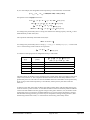
Depth coefficients dc dd and db
The depth coefficients take into account the favourable influence of shear strength in the failure
plane above the footing base. In DIN 4017:2006 this effect is not taken into consideration, i.e. all
depth coefficients are 1.0. In some European countries, on the other hand, the favourable effect
may be considered by adopting depth coefficients > 1.0.
The following tables show a number of depth coefficient equations, compiled by Ziegler/Tafur
(2015) in the context of a PRB project (PRB = Initiative Praxisgerechte Regelwerke im Bauwesen
e.V., www.initiative-prb.de).
The coefficient db in all cases is:
db = 1,0
For the influence of the embedment depth dd:
d d 1 2 tan 1 sin
2
Brinch Hansen:
Bulletin N° 28 (1970) 2)
d
b'
d
2
d d 1 2 tan 1 sin tan 1
b'
Lang et al. (Switzerland) 3)
d
2
d d 1 0,035 tan 1 sin tan 1
b'
IEG7: Plattgrundläggning
(Sweden) 4)
d d 1 0,35
GCOC (Spain) 5)
d
2
d d 1 2 tan 1 sin tan 1
b'
d
b'
d b'
d > b'
dd 1,7
d 2b'
For the influence of cohesion dc:
d c 1 0,35
Brinch Hansen:
Bulletin N° 11 (1961) 1)
dc 1
d
b'
0,35
b'
0,6
d 1 7 tan 4
Lang et al. (Switzerland)
d
d c 1 0,007 tan 1
b'
IEG7: Plattgrundläggning
(Sweden)
d c 1 0,35
GCOC (Spain)
dc 1 2
Nq
Nc
d b'
d
b'
d
2
1 sin tan 1
b'
d > b'
dc 1,7
d 2b'
1)
Brinch Hansen, J. (1961): A general formula for bearing capacity, Bulletin No11, Geoteknisk Institut, Copenhagen
Brinch Hansen, J. (1970): A revised and extended formula for bearing capacity, Bulletin No28, Geoteknisk Institut,
Copenhagen
3)
Lang, H.-J., Huder, J., Amann, P., Puzrin, A. (2011): Bodenmechanik und Grundbau, 9. Auflage, Springer-Verlag
4)
IEG Rapport 7:2008 (2010): Tillämpningsdokument, EN 1997-1 kapitel 6, Plattgrundläggning, Schweden
5)
GCOC (2009): Guía de cimentaciones en obras de carretera, Madrid
2)
GGU-FOOTING User Manual
Page 35 of 81
April 2015
6.2
Theoretical principles circle/annulus
The bearing capacity of a circular footing is calculated using the equations given in DIN 4017
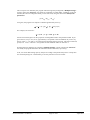
An equivalent area A' must be determined for eccentric loading. For a rectangle, for example, the
equivalent area is given by:
A' = (a - ex) · (b - ey)
where:
ex , ey = eccentricities
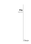
The equivalent area for a circle is calculated as shown in the figure below:
Figure 2 Equivalent area for circle (Leibniz University, Hannover)
The 1st and 2nd core dimensions are also required. For a circle:
Core dimensions for circle:
1st core dimension = D/8
2nd core dimension = 3·π·D/32
There are no bearing capacity equations for an annulus comparable to those for a circle. The annulus is therefore converted to an equivalent circle. The conversion can be performed using either an
equal area circle or a circle with the same moment of inertia.
Core dimensions for annulus:
1st core dimension = [1+ (Di / Da)2]·Da /8
2nd core dimension = 3·π·Da/32·[1- (Di/Da)4] / [1- (Di/Da)3]
where:
Di = diameter (inner)
Da = diameter (outer)
GGU-FOOTING User Manual
Page 36 of 81
April 2015
Settlement analyses are performed using triangular load areas, allowing the loads on a circle or an
annulus to be exactly modelled [Dr.-Ing. Johann Buß, Setzungen und Spannungen unter "Dreiecksfundamenten" (Settlements and Stresses below Triangular Footings), Geotechnik 22 (1999)
No. 1].
The position of the characteristic point is required for settlement analyses. For a circle:
Characteristic point for circle = 0.845 · R
The characteristic point cannot be derived for the annular footing. Conservative calculations assume that the characteristic point is in the same location as for a circle
Characteristic point for annulus assumption = circle = 0.845 · Ra
where:
6.3
Ra = outer radius
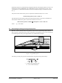
Determining the mean governing soil properties
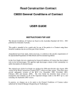
DIN 4017 instructs that the mean soil properties of the soil above the bearing capacity failure
plane, which is composed of the two linear components of a logarithmic spiral, can be determined
for stratified ground. The governing parameters are summarised in the figure:
calc
45 -/ 2
GK1
GK 3
90 -
GK 2
90 -
Figure 3 Logarithmic spiral
The mean governing soil properties are determined using the following relationships:
cal tan = tan i · li’ / li
cal c= ci · li’ / li
cal 2 = 2i · Ai’ / Ai
li = length within individual layer
Ai = area of individual layer
GGU-FOOTING User Manual
Page 37 of 81
April 2015
The weight of the soil above slip body GK 3 is summed, including and distributed and line loads
present and converted to an idealised body 1 · d.
Large line loads can generate a substantial increase in an imaginary embedment depth. This
is associated with soil pressures, which cannot be activated as calculations would indicate.
The DIN 4017, for example, assumes that the ratio between embedment depth d and footing width b will achieve a maximum of 2.0 in order to guarantee the validity of a bearing
capacity analysis. You should therefore examine your input data with this in mind. The
same effect can be achieved by defining very large embedment depths.
The condition for the permissibility of the mean is that the mean friction angle demonstrates a
maximum deviation of 5° to the true friction angles. This condition can be checked by the program. If it is not adhered to, the program reduces the largest friction angle in stages until the condition is met.
6.4
Differences between DIN 1054 (old) and DIN 1054:2005/EC 7
The differences between DIN 1054 (old) and 1054:2005 or EC 7 are minor for bearing capacity
analysis.
The failure load, or, using partial safety factors, the characteristic bearing capacity (Rk) is determined identically. This value is subsequently divided by the bearing capacity partial safety factor
bearing capacity (Table 3 in DIN 1054:2005). This is 1.40 for load case 1, 1.30 for load case 2 and
1.20 for load case 3. This leads to the bearing capacity design value Rd
Rd = Rk / bearing capacity
This value is compared to the design value for the present load (action) Vd. The design value is
given by the load present or, using partial safety factors, by the characteristic action Vk multiplied
by the partial safety factor for the actions G (permanent) and Q (changeable). According to Table
2 (DIN 1054:2005), the following partial safety factors must be adopted:
Permanent actions: (1.35 LC 1, 1.20 LC 2 and 1.00 LC 3)
Unfavourable changeable actions: (1.50 LC 1, 1.30 LC 2 and 1.00 LC 3)
If the characteristic action consists of a permanent (index G) and a changeable (index Q) action,
the design value Vd is
Vd = G · Vk,G + Q · Vk,Q
The bearing capacity has been verified if
Vd Rd
is shown. A safety factor according to the global safety factor concept
= failure load/present load
is currently not envisaged. However, the safety factor according to the global safety factor concept has the great advantage that the distance to safe conditions is documented with a single number.
GGU-FOOTING User Manual
Page 38 of 81
April 2015
e.g. for load case 1 according to the global safety factor concept:
= 2.01 = just adhered to for allowable = 2.00
or
= 16.26 = generously dimensioned for allowable = 2.00
So a utilisation factor is defined by = Vd / Rd
A value of smaller than 1.0 therefore indicates stable conditions.
A simple example (load case 1) will demonstrate the differences between DIN 1054 (old) and
DIN 1054:2005.
DIN 1054 (old)
pres. V = 1000 kN
VFailure = 2100 kN (via bearing capacity analysis)
= 2100/1000 = 2.10 > allow. = 2.00
DIN 1054:2005
Vk,G = 400 kN (permanent) = characteristic permanent load
Vk,Q = 600 kN (changeable) = characteristic changeable load
Vd = G · Vk,G + Q · Vk,Q = 1.35 · 400 + 1.50 · 600 = 1,440 kN
Vd = 1,440 kN = load design value
Rk = VFailure (according to DIN 1054 (old)) = 2,100 kN (via bearing capacity analysis)
Rk = characteristic bearing capacity
Rd = Rk / Bearing capacity = 2,100/1.40 = 1,500
Rd = bearing capacity design value
= Vd / Rd = 1,440/1,500 = 0.96
An utilisation factor in accordance with the partial safety factor concept can be acquired for the
global safety factor concept by dividing the allowable safety factor by the present safety factor.
(DIN 1054 (old)) = allow. (DIN 1054 (old)/pres. (DIN 1054 (old) = 2.00/2.10 = 0.95
This value roughly corresponds to the value for the partial safety factor concept. In principle, then,
nothing has changed.
From the relationship for the utilisation factor according to the partial safety factor concept
= V d / Rd ,
an allowable load can be computed if the utilisation factor is set to = 1.0.
= (G · Vk,G + Q · Vk,Q) / (Rk / Bearing capacity)
1,0 = (G · Vk,G + Q · Vk,Q) / (Rk / Bearing capacity)
Vk,G = permanent loads
Vk,Q = changeable loads
GGU-FOOTING User Manual
Page 39 of 81
April 2015
If, as in the example, the changeable loads component p is more than 60% of total loads
p = Vk,Q / (Vk,G + Vk,Q) = 600/(600 + 400) = 0.60 [= 60%]
the equation can be simplified as follows:
1.0 = (G · (1 – p) · Vk + Q · p · Vk) / (Rk / Bearing capacity)
1.0 = (G · (1 – p) + Q · p) · Vk / (Rk / Bearing capacity)
(G · (1 – p) + Q · p) · Vk = Rk / Bearing capacity
allow. Vk = Rk / [(G · (1 – p) + Q · p) · Bearing capacity]
According to the partial safety factor concept, the characteristic bearing capacity value Rk is calculated identically to DIN 1054 (old).
The equivalent relationship from DIN 1054 (old) is:
allow. V = VFailure /
According to the partial safety factor concept, G = 1.35, Q = 1.50 and Bearing capacity = 1.40 for load
case 1. The following values result for the expression
(G · (1 – p) + Q · p) · Bearing capacity
as a function of the proportion of changeable loads p to total loads:
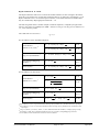
p [-]
p [%]
(G · p + Q · (1 – p)) · Bearing capacity
(1.35 · (1 – p) + 1.50 · p) · 1.40
0.000
0.0
1.89
0.333
33.3
1.96
0.500
50.0
1.99
0.667
66.7
2.03
1.000
100.0
2.10
The third column in the table can be compared to the constant safety factor according to DIN 1054
(old) of 2.0 (load case 1). The comparison demonstrates that this not noticeably different to the
global safety factor of 2.00. This was also the laudable intention of the authors of the partial safety
factor concept. If the load component p is around 50%, almost precisely the same results are
achieved.
In analogy to the DIN 1054 (old), the DIN 1054:2005 contains tables with allowable footing pressures for various systems in Annex A. The tables and table values are absolutely identical with the
values in the old standard. The may appear strange at first glance. But here, too, the authors of the
partial safety factor concept have orientated themselves to proven systems and analysis concepts.
The allowable footing pressures given here may be compared to existing footing pressures, determined using characteristic loads, i.e. with loads not increased by partial safety factors.
GGU-FOOTING User Manual
Page 40 of 81
April 2015
This concept is also utilised by the program when footing analysis diagrams ("Multiple footings"
switch in menu item "File/New" activated) are calculated. You then define, in addition to the old
standard, the ration of changeable loads p to the total loads, using the menu item "Edit/System
parameters"
p = Vk,Q / (Vk,G + Vk,Q)
Using this, the program can compute a substitute global safety factor ':
' = (G · (1 – p) + Q · p) · Bearing capacity
For example, for load case 1:
' = (1.35 · (1 – p) + 1.50 · p) · 1.40
Ask the structural engineer for the proportion of changeable loads in the permanent loads. If you
get no answer, set p to 0.5 (50 %, approximately corresponds to the old standard). If you are very
unsure, select p = 1.0 (100 %). You then get the allowable footing pressures, which are around 5%
[2.00/(1.50 · 1.40) = 2.00/2.10 = 0.95] below the old standards values for load case 1.
If footing analysis diagrams are computed ("Multiple footings" switch in menu item "File/New"
activated), the program determines the settlements under total load (as previously).
In all, it is shown that bearing capacity analysis according to the partial safety factor concept does
not contain anything new. Unfortunately, it has only become a lot more unclear.
GGU-FOOTING User Manual
Page 41 of 81
April 2015
6.5
Settlement analysis
Settlement analysis are carried out according to DIN 4019. Once the program has determined the
characteristic or allowable footing pressure for the proposed footing, the settlements are determined using these characteristic or allowable values. DIN 4019 Table 1 allows correction coefficients kappa to be taken into consideration for modelling settlements (see menu item "File/New",
Section 7.1.1).
The program calculates stresses and deformations according to the theory of elastic-isotropic halfspace. Very comprehensive diagrams and tables were developed, particularly in the time before
pocket calculators and personal computers were available. A bibliography of tables can be taken
from DIN 4019. Please also see the article "Spannungsberechnung" ("Stress analysis") in the Geotechnical Engineering Handbook (1990; Fourth edition). This also contains complete relationships
for deformations and stresses below a rectangle in elastic-isotropic half-space (equations 8 to 10
and equations 14 and 15). The program is based on these relationships.
The stress relationships are only utilised for limiting depth calculations and for representation of
stress distributions. The deformations are calculated directly from the relationships given in the
Geotechnical Engineering Handbook. Numerical integration with associated loss of precision id
therefore not necessary. If a base tilt results when analysing a pad footing these relationships can
no longer be used because the pressure zone is no longer rectangular. In this case, an analyticalnumerical settlement analysis is required.
The limiting depth can be defined in three different ways:
with a fixed, user-defined value
as a multiple of the footing width
as the depth at which the total vertical stress exceeds the overburden stress by x% (as a rule
20%).
The settlement curves in the footing analysis diagram are attained from the footing pressure by
linear interpolation. Thus, analysis using the x%-criteria only takes place for the maximum footing
pressure of each footing width. However, if you open "Edit/Analysis options" menu item and
activate the "Stress variable" check box, the limiting depth is calculated for a number of stresses
(here for 25 stresses).
GGU-FOOTING User Manual
Page 42 of 81
April 2015
7 Description of menu items
7.1
7.1.1
File menu
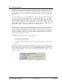
"New" menu item
The dialog box shown in the examples opens. First, select the equation for calculating the bearing
capacity in the combo box. In addition to the standard DIN 4017:2006 and DIN 4017 (old) methods, the methods after Terzaghi, Meyerhoff, Hansen and Vesic well known from many literature
references may also be selected. If the Terzaghi, Meyerhoff, Hansen or Vesic analysis methods are
adopted, the English designations can be used in the bearing capacity equations in addition to the
German designations.
You must then specify whether analysis will use the partial safety factor concept to EC 7 or
DIN 1054:2005 or the old global safety factor concept. Decide whether you want to analyse a pad
footing (rectangular or circular/annular footing) or multiple footings of a certain type (with footing
analysis diagram).
With the introduction of EC7, the table value "Allowable bearing pressure" used in the tables for
spread footing analyses is generally replaced by the table value "Bearing pressure design value".
Differences to DIN 1054:2005 in terms of footing dimensions do not result from this. If you are
working to EC7, "sigma(R,d)" for design and output is activated.
DIN 1054:2005 states that an overturning analysis may be dispensed with for Load Case 3 if sufficient bearing capacity has been demonstrated. This rule is no longer included in Eurocode 7; it is
therefore always necessary to perform an overturning analysis. In justified exceptional cases, however, the analysis may be turned off using the "Do not investigate overturning" check box.
The next part of the dialog box is only active if you are analysing using global safety factors. Here
you can specify whether the reference parameter for safety is the "Load" or the "Shear coefficients" (friction angle and cohesion). In this case you must enter a safety factor for both the friction angle and the cohesion (see menu item "Edit/System parameters").
GGU-FOOTING User Manual
Page 43 of 81
April 2015
If the "Use absolute heights" check box is activated, enter the layer depths, the groundwater level
and the footing base in absolute values (y-axis positive upwards), e.g. in m AD. In addition, the
ground level must be given in the "Edit/System parameters" dialog box. Otherwise, the ground
level will be at 0.0 and all depth input is positive downwards.
If the height of a previously defined system is subsequently set to absolute heights, a query follows after leaving the dialog box above asking for confirmation of whether soil strata should be
adapted to the new ground level. Adaptation would mean that the depth of a soil layer entered as a
positive value would be converted from, for example, 7.5 m to an absolute height of -7.5 m AD.
If, then, you only convert your system to [m AD], press the "No" button.
DIN 4019 Table 1 allows correction coefficients kappa to be taken into consideration for modelling settlements. These correction coefficients can be activated using the appropriate check box in
the dialog box.
DIN 4017:2006 describes a new punching analysis method. To use this new analysis method the
"Punching analysis using new method (recommended)" check box is activated by default when
the program starts. This means it is now only necessary to specify whether a flexible footing is
being dealt with in the "Edit/System parameters" dialog box (see Example 1, Section 5.2.2).
If you wish you can enter a description of the problem being worked on in this dialog box; this
will then be used in the General legend. Otherwise the project identification is entered using the
menu item "Edit/Project identification".
After confirming your input with "OK" you will see an info box corresponding to your safety
concept with the safety factors or partial factors for the various load cases. Close the box by clicking on the load case of your choice. The safety factor values are automatically used in the system
data. If the partial safety factor concept is adopted, the load case can be modified at any time
using the "Edit/Partial safety factors" menu item (see Section 7.2.9). If a different load case is
required when carrying out an analysis using the global safety factor concept, proceed via the
"File/New" menu item
7.1.2
"Load" menu item
You can load a file with system data, which was created and saved at a previous sitting, and then
edit the system.
7.1.3
"Save" menu item
You can save data entered or edited during program use to a file, in order to have them available at
a later date, or to archive them. The data is saved without prompting with the name of the current
file.
7.1.4
"Save as" menu item
You can save data entered during program use to an existing file or to a new file, i.e. using a new
file name. For reasons of clarity, it makes sense to use ".gdg" as file suffix, as this is the suffix
used in the file requester box for the menu item "File/Load". If you choose not to enter an extension when saving, ".gdg" will be used automatically.
GGU-FOOTING User Manual
Page 44 of 81
April 2015
7.1.5
"Print output table" menu item
7.1.5.1
Output as graphics
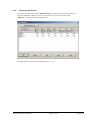
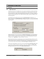
You can have an output table printed containing all information on the current state of analysis,
including the system data.
In a further option box in the "Multiple footings" analysis mode it is possible to choose between a
graphical output table or one in ASCII format. If you click the "Output as graphics" button you
will see the following dialog box. In the "Pad footing" analysis mode it opens automatically when
this menu item is selected.
You can define the desired layout for the output table in various areas of the dialog box. If you
need to add a header or footer (e.g. for page numbering), activate the appropriate check boxes
"With headers" and/or "With footers" and click on the "Edit" button. You can then edit as required in a further dialog box.
GGU-FOOTING User Manual
Page 45 of 81
April 2015
Automatic pagination can also be employed here if you work with the placeholders as described.
After exiting the dialog boxes using "OK" you will see a further dialog box in which you can
select the parameters to be used in the output table. If you click the "OK" button the output table
is presented on the screen page by page. To navigate between the pages, use the arrow tools
in the toolbar. If you need to jump to a given page or back to the graphical representation, click on the
tool. You will then see the following box:
GGU-FOOTING User Manual
Page 46 of 81
April 2015
7.1.5.2
Output as ASCII
When in the "Multiple footings" analysis mode, you can have your calculation data sent to the
printer, without further work on the layout, or save it to a file for further processing using a different program, e.g. a word processing application.
In the option box for this menu item simply press the "Output as ASCII" button. You will see the
following dialog box for specifying the simple table output:
"Printer preferences" group box
Using the "Edit" button the current printer preferences can be changed or a different printer
selected. Using the "Save" button, all preferences from this dialog box can be saved to a
file in order to have them available for a later session. If you select "GGUFOOTING.drk" as file name and save the file in the program folder (default), the file will
be automatically loaded the next time you start the program.
Using the "Page format" button you can define, amongst other things, the size of the left
margin and the number of rows per page. The "Header/footer" button allows you to enter
a header and footer text for each page. If the "#" symbol appears within the text, the current
page number will be entered during printing (e.g. "Page #"). The text size is given in "Pts".
You can also change between "Portrait" and "Landscape" formats.
"Print pages" group box
If you do not wish pagination to begin with "1" you can add an offset number to the check
box. This offset will be added to the current page number. The output range is defined using "From page no." "to page no.".
"Output to:" group box
Start output by clicking on "Printer" or "File". The file name can then be selected from or
entered into the box. If you select the "Window" button the results are sent to a separate
window. Further text editing options are available in this window, as well as loading, saving and printing.
GGU-FOOTING User Manual
Page 47 of 81
April 2015
7.1.6
"Printer preferences" menu item
You can edit printer preferences (e.g. swap between portrait and landscape) or change the printer
in accordance with WINDOWS conventions.
7.1.7
"Print and export" menu item
You can select your output format in a dialog box. You have the following possibilities:
"Printer"
allows graphic output of the current screen contents (graphical representation) to the
WINDOWS standard printer or to any other printer selected using the menu item
"File/Printer preferences". But you may also select a different printer in the following
dialog box by pressing the "Printer prefs./change printer" button.
In the upper group box, the maximum dimensions which the printer can accept are given.
Below this, the dimensions of the image to be printed are given. If the image is larger than
the output format of the printer, the image will be printed to several pages (in the above example, 4). In order to facilitate better re-connection of the images, the possibility of entering an overlap for each page, in x and y direction, is given. Alternatively, you also have the
possibility of selecting a smaller zoom factor, ensuring output to one page ("Fit to page"
button). Following this, you can enlarge to the original format on a copying machine, to ensure true scaling. Furthermore, you may enter the number of copies to be printed.
GGU-FOOTING User Manual
Page 48 of 81
April 2015
If you have activated the tabular representation on the screen, you will see a different dialog box for output by means of the "File/Print and export" menu item button "Printer".
Here, you can select the table pages to be printed. In order to achieve output with a zoom
factor of 1 (button "Fit in automatically" is deactivated), you must adjust the page format
to suit the size format of the output device. To do this, use the dialog box in "File/Print
output table" button "Output as graphics".
"DXF file"
allows output of the graphics to a DXF file. DXF is a common file format for transferring
graphics between a variety of applications.
"GGUCAD file"
allows output of the graphics to a file, in order to enable further processing with the
GGUCAD program. Compared to output as a DXF file this has the advantage that no loss
of colour quality occurs during export.
"Clipboard"
The graphics are copied to the WINDOWS clipboard. From there, they can be imported
into other WINDOWS programs for further processing, e.g. into a word processor. In order
to import into any other WINDOWS program you must generally use the "Edit/Paste"
function of the respective application.
"Metafile"
allows output of the graphics to a file in order to be further processed with third party software. Output is in the standardised EMF format (Enhanced Metafile format). Use of the
Metafile format guarantees the best possible quality when transferring graphics.
If you select the "Copy/print area" tool
from the toolbar, you can copy parts of
the graphics to the clipboard or save them to an EMF file. Alternatively you can send
the marked area directly to your printer (see "Tips and tricks", Section 8.3).
Using the "Mini-CAD" program module you can also import EMF files generated using other GGU applications into your graphics.
GGU-FOOTING User Manual
Page 49 of 81
April 2015
"MiniCAD"
allows export of the graphics to a file in order to enable importing to different GGU applications with the Mini-CAD module.
"GGUMiniCAD"
allows export of the graphics to a file in order to enable processing in the GGUMiniCAD
program.
"Cancel"
Printing is cancelled.
7.1.8
"Batch print" menu item
If you would like to print several appendices at once, select this menu item. You will see the following dialog box:
Create a list of files for printing using "Add" and selecting the desired files. The number of files is
displayed in the dialog box header. Using "Delete" you can mark and delete selected individual
files from the list. After selecting the "Delete all" button, you can compile a new list. Selection of
the desired printer and printer preferences is achieved by pressing the "Printer" button.
You then start printing by using the "Print" button. In the dialog box which then appears you can
select further preferences for printer output such as, e.g., the number of copies. These preferences
will be applied to all files in the list.
7.1.9
"Exit" menu item
After a confirmation prompt, you can quit the program.
7.1.10
"1, 2, 3, 4" menu items
The "1, 2, 3, 4" menu items show the last four files worked on. By selecting one of these menu
items the listed file will be loaded. If you have saved files in any other folder than the program
folder, you can save yourself the occasionally onerous rummaging through various sub-folders.
GGU-FOOTING User Manual
Page 50 of 81
April 2015
7.2
7.2.1
Edit menu
"Analysis options" menu item
A dialog box opens similar to that for the menu item "File/New" (see Section 7.1.1). Only the
project identification cannot be entered here.
The dialog box has been extended by the group box "Limiting depths in footing analysis diagram", where the type of limiting depth calculation for "Multiple footings" is specified (see
"Theoretical principles/Settlement analysis" in Section 6.5). You can read a brief description by
pressing the "Info" button.
If the pad footing analysis mode ("Rectangular footing"/"Circular/annular footing") is selected,
the "Limiting depths in footing analysis diagram" group box is deactivated. Because the footing
stress is specified directly in the menu item "Edit/Footing details" in this analysis mode (see
Section 5.3.3), calculation of the limiting depth by means of stress variables is not required.
7.2.2
"Project identification" menu item
You can enter a description of the current system; this will then be used in the General legend
(see Section 7.4.5).
GGU-FOOTING User Manual
Page 51 of 81
April 2015
7.2.3
"System parameters" menu item
This function can also be accessed using the [F3] function key. The following dialog box opens if
"Multiple footings" are selected together with systems analysed to DIN 4017:2006 and using the
partial safety factor concept. The partial safety factor values are already entered into the input
boxes, depending on the load case selected. If the global safety factor concept is selected, only the
input boxes for the safety factors change, the remaining buttons and boxes are identical.
The input boxes have already been described in the "Multiple footings" worked example in Section 5.2.2 and in the "Single rectangular footing" worked example in Section 5.3.2.
Input of "Ground level" is required when working with absolute heights, e.g. in m AD. "Groundwater table" and "Footing base" are given correspondingly in m AD.
If you analyse with the "Shear coefficients" reference parameter using the global safety factors
you must specify two safety factors (friction angle and cohesion).
GGU-FOOTING User Manual
Page 52 of 81
April 2015
7.2.4
"Footing details" menu item
Depending on the analysis mode and the safety factor concept selected, you will see a modified
dialog box for input of footing sizes and/or stresses (see worked examples; Sections 5.2.3, 5.3.3
and 5.4.3).
The following dialog box opens in the "Rectangular footing" analysis mode using partial safety
factors:
Enter the dimensions and stresses for the footing. According to the partial safety factor concept,
you can define differing stresses for permanent and changeable loads (live loads). Instead of the
footing analysis diagram seen in the "Multiple footings" analysis mode a plan view of a pad footing (rectangle or circle/annulus) is shown with the loading values, among other things.
The friction angle of the soil at the footing base is adopted when analysing the sliding resistance
of a pad footing (rectangle or circle/annulus). Any user-defined angle can be adopted by activating
the "Sliding resistance with user-defined angle" check box. This can be useful if soils with a low
friction angle are prevalent below the base of the footing, for example.
GGU-FOOTING User Manual
Page 53 of 81
April 2015
GGU-FOOTING can also analyse the torsional stiffnesses of footings. Circular or annular footings are often used for the foundations of wind energy converters. In this program version a circular/annular footing can be selected by going to the menu item "Edit/Analysis options". In this
menu item you are then presented with a correspondingly modified dialog box for defining the
footing (see Example 3: "Single circular footing", Section 5.4.3).
In older program versions it was possible to convert the circular or annular footing data to a square
footing (see dialog box above) to determine the torsional stiffnesses for a rectangular footing by
pressing the "Equivalent width from circle/annulus" button in the above dialog box.
7.2.5
"Soils" menu item
Enter the number of soil layers and the corresponding soil properties here. An explanation of the
dialog box can be found in Section 5.2.4.
7.2.6
"Limiting depth" menu item
You can define the way in which the limiting depth is calculated. An explanation of the dialog box
can be found in the "Multiple footings" worked example in Section 5.2.5.
GGU-FOOTING User Manual
Page 54 of 81
April 2015
7.2.7
"Line loads" menu item
You can define up to 5 line loads acting as surcharges on the bearing capacity failure body.
The number of line loads can be modified using the "x line load(s) to edit" button.
Line load
Spacing
Width
Figure 4 Line load
GGU-FOOTING User Manual
Page 55 of 81
April 2015
7.2.8
"Berms" menu item
A maximum of five berms may be defined using this menu item depending on the analysis method
selected. The berms may not overlap. The program checks that this condition is adhered to and
warns of any errors. Any berms defined using "Edit/System parameters" are set to 0.0 if you
define one or more berms using this menu item.
0.00
-2.0/0.0
0.5
-4.0/0.5
10.0 kN/m²
-3.0/0.5
0.5
GS = 1.00
1.0
2.0
GS = 1.00
1.0
-7.0/1.5
1.5
1.000
0.630
GW = 2.00
0.466
1.5
2.5
0.358
3.0
0.283
3.5
a
4.0
[m]
2.0
b
[m]
zul
[kN/m²]
zul V
[kN/m]
s
[cm]
cal
[°]
cal c
[kN/m²]
2
[kN/m³]
Ü
[kN/m²]
tg
[m]
GW = 2.00
0.231
UK LS
[m]
10.00
4.5
0.40
231.9
92.8
0.98
27.5
5.00
20.00
20.00
4.43
1.58
10.00
0.50
239.4
119.7
1.14
27.5
5.00
20.00
20.00
4.94
1.73
2.00
0.193
0.163
2.5
0.141
Figure 5 Berms
To get the berms shown in Figure 4 enter the values into the dialog box as shown:
Enter the x-ordinate of the toe and the head. Define the height of the berm with "delta h". Negative values are also allowed here. Finally, a surcharge load can be specified for the horizontal area
behind the head of the berm.
GGU-FOOTING User Manual
Page 56 of 81
April 2015
7.2.9
"Partial safety factors" menu item
If you are analysing with the partial safety factor concept , you will see a dialog box for defining
the partial factors.
By pressing the appropriate button the partial factors for the various load cases given in DIN
1054:2005 and EC 7 can be adopted. The load case designations were altered for the EC 7 partial
safety factor concept:
Load Case 1 is now DS-P: Persistent Design Situation
Load Case 2 is now DS-T: Transient Design Situation
Load Case 3 is now DS-A: Accidental Design Situation
In addition, there is a seismic design situation (DS-E). In the DS-E design situation all partial
factors = '1,0'. The load case correlation to ÖNORM EN 1997-1 will be shown by clicking on the
corresponding button. The partial safety factors are automatically adopted in the system data (see
menu item "Edit/System parameters", Section 7.2.3).
GGU-FOOTING User Manual
Page 57 of 81
April 2015
7.3
7.3.1
System menu
"Analyse" menu item
When you edit any of the system data using the "Edit" menu item, the diagrams presented do not
represent the current analysis results. Only after using this menu item is the modified system reanalysed and subsequently presented with the new results. Alternatively, you can use the [F5]
function key or the calculator in the toolbar. A running analysis can be stopped by pressing the
right mouse button.
In the "Rectangular footing" analysis mode, the bearing capacity safety is calculated for both
directions. Naturally, the smaller value is critical. Information on the conditions in the other direction can be viewed in the "Pad footing" legend. Preferences for this can be defined in the "Output preferences" menu (see Section 7.4.7, "For both directions" check box).
7.3.2
"Optimise footing width" menu item
This menu item is only active in the pad footing analysis mode! Alternatively, footing optimisation can also be started by pressing [F6].
If "Rectangular footing" is selected, the following dialog box opens:
After confirming with "OK" optimisation is carried out, at the end of which you may opt to use
the optimum width. A new computation is performed immediately after confirmation. If you
choose not to accept the optimum width the menu item is closed.
If "Circular/annular footing" is selected, optimisation is performed for the outer circle diameter.
The inner diameter is retained.
GGU-FOOTING User Manual
Page 58 of 81
April 2015
7.4
7.4.1
Output preferences menu
"Footing analysis diagram" menu item
This menu item only appears in the "Multiple footings" analysis mode. When the "Show footing
analysis diagram" check box is activated, you can define preferences for representation of the
footing analysis diagram.
You can define and edit the position of the legend using the values "x" and "y". The size of the
legend is controlled by the values for "Width" and "Height".
The fastest way to modify the position or size of the legend is to press the [F11] function
key and then to either pull the legend to the new position or to move the sides of the legend
to their new size with the left mouse button pressed.
In the second group box the smoothing out method for drawing the graphs for settlement, limiting
depths or the modulus of subgrade reaction in the footing analysis diagram can be selected:
"Linear"
= no smoothing
"Method 1"
= 'strict' Bezier spline
"Method 2"
= 'loose' Bezier spline
GGU-FOOTING User Manual
Page 59 of 81
April 2015
Using the default settings the diagram is automatically scaled. If you select the "User-defined
axes" button you are first offered the automatic scaling values in a box, which you can then edit as
wished. If you activate the "Use specified fixed scales" check box, the values entered in the "Output preferences/Fixed scales" menu item (see Section 7.4.11) are used.
In the fourth group box you can influence the representation of the settlement curves. The settlement curves are represented in the diagram using the three numbers given in the box above. The
program calculates the settlements corresponding to a given footing width by means of linear
interpolation. If the limiting depth is calculated using the "% condition" (see Worked example 1,
Section 5.2.5) and you have activated the "Stress variable" check box in the "Edit/System parameters" menu item (see "Theoretical principles/Settlement analysis", Section 6.5), limiting
depth curves or SR moduli curves can be represented instead of settlement curves.
The (allowable) bearing pressure, or the (allowable) strip load or point load can be selected for
visualisation on the y-ordinate in the diagram when analysing using the partial safety factor concept. If the global safety factor concept is employed either the allowable footing pressure or the
allowable strip or point load can be selected.
If you activate the "Hatch allowable area" check box, reference lines are drawn in the allowable
area only. Otherwise, lines are drawn across the whole of the plan width and height. Moreover,
additional scaling of the footing analysis diagram using the values for sigma(E,k) can be activated
here.
GGU-FOOTING User Manual
Page 60 of 81
April 2015
7.4.2
"Footing plan" menu item
This menu item only appears in the pad footing analysis mode ("Rectangular footing"/
"Circular/annular footing"). If the "Show footing plan" check box is activated the graphical
visualisation can be adapted in the dialog box associated with this menu item.
You can define and edit the position of the legend using the values "x" and "y". The size of the
legend is controlled by the values for "Width" and "Height". The labelling font size can be altered.
The fastest way to modify the position or size of the legend is to press the [F11] function
key and then to either pull the legend to the new position or to move the sides of the legend
to their new size with the left mouse button pressed.
Besides position and size of the footing plan view, you can specify a number of preferences for
representation of further result data. The dialog box is self-explanatory. Experiment a little. After
closing the dialog box the modifications are immediately shown on the screen. However, the system should have been previously analysed.
GGU-FOOTING User Manual
Page 61 of 81
April 2015
7.4.3
"Soil properties" menu item
A soil properties legend is shown on the screen when you activate the "Show legend" check box.
The format and appearance of the legend can be altered using this menu item.
You can define and edit the position of the legend using the values "x" and "y". The size of the
legend is controlled by the values for "Font size".
The fastest way to modify the position of the legend is to press the [F11] function key and
then to pull the legend to the new position with the left mouse button pressed.
The depths of the soil layers can also be entered in the legend. Poisson's ratio can be switched off
in the legend, for example if Poisson's ratio nu = 0.0 for all soils.
If the "System coloured" combo-box is activated, the soils will be displayed coloured in the legend and in the system and stress distribution graphics. Otherwise, they will be numbered. If you
deactivate the "Automatic" check box in the "Soil colours + hatching" group box, the soil colours will be selected according to your individual preferences, which you can edit using the "Soil
colours" button. Alternatively, you have the option of applying a variety of hatches. Using the
legend hatching factor, closer hatching of the soil legend can be achieved than is possible in the
system and stress influence diagrams.
GGU-FOOTING User Manual
Page 62 of 81
April 2015
7.4.4
"System presentation" menu item
You can alter the shape and appearance of the system presentation, when the "Show legend"
check box is activated. Here, the dialog box for "Multiple footings" is represented.
You can define and edit the position of the system presentation using the values "x" and "y". The
size is controlled by the values for "Width" and "Height". The fastest way to modify the position
or size of the legend is to press the [F11] function key and then to either pull the legend to the new
position or to move the sides of the legend to their new size with the left mouse button pressed.
In addition, you can have the logarithmic spiral represented for various footing widths. The soil
names can be displayed at the left, central or at the right . If you activate the "Label logarithmic
spiral" check box, the x ordinates are shown. You can rotate the graphics by using the "Display
bearing cap. failure plane to left" check box; the analysis results do not alter.
If you are working on a system with low-lying groundwater, such that groundwater has no influence on the analysis results, you can deactivate the "With groundwater" check box. The groundwater table will then not be included in the graphical representation. Otherwise, the graphics will
be reduced until the groundwater table also fits into the diagram, which can lead to very compact
and unclear representations. Of course, the analysis results are not influenced by this check box,
even if the groundwater table is later raised into the zone of influence of the logarithmic spiral.
The dimensions of a berm defined as described in Section 7.2.8 can be displayed using the "Berm
labelling" button. There are also a number of options available for visualising loads.
GGU-FOOTING User Manual
Page 63 of 81
April 2015
7.4.5
"General legend" menu item
A legend with general properties will be displayed on your output sheet, if the "Show legend"
check box is activated. You can alter the type of visualisation using the dialog box of this menu
item.
You can define and edit the position of the legend using the values "x" and "y". You control the
size of the legend using "Font size" and "Max. no. of lines"; where necessary, several columns
are used.
The fastest way to modify the position of the legend is to press the [F11] function key and
then to pull the legend to the new position.
In the General legend you can, if wished, display information on the program (name and version),
on the adopted standard and on the current file (name, path, time info). Any project identification
entered in the "File/New" or "Edit/Project identification" dialog box will be shown automatically in the General legend.
By activating the check boxes "With comment on bearing cap. failure" and "With comment on
settlement" the use of the lines in the footing analysis diagram is explained ("Multiple footings"
analysis mode).
GGU-FOOTING User Manual
Page 64 of 81
April 2015
7.4.6
"Output table" menu item
This menu item only appears in the "Multiple footings" analysis mode. You can alter the shape
and appearance of the analysis output table, when the "Show output table" check box is activated.
You can define and edit the position of the legend using the values "x" and "y". The size of the
legend is controlled by the values for "Width" and "Height". The font size is adjusted to fit the
available space.
The fastest way to modify the position or size of the legend is to press the [F11] function
key and then to either pull the legend to the new position or to move the sides of the legend
to their new size with the left mouse button pressed.
The check boxes at the bottom of the box allow you to select a number of additional parameters to
be entered in the output table. If the "SR modulus" check box is activated, the characteristic or
allowable footing pressure is divided by the corresponding settlement for each footing and shown
as the subgrade reaction modulus ks in [MN/m³].
GGU-FOOTING User Manual
Page 65 of 81
April 2015
7.4.7
"Pad footing" menu item
This menu item only appears in the pad footing analysis mode ("Rectangular footing"/
"Circular/annular footing"). An analysis results legend is shown on the screen when the "Show
legend" check box is activated. The format and appearance of the legend can be altered using this
menu item.
You can define and edit the position of the legend using the values "x" and "y". You control the
size of the legend using "Font size" and "Max. no. of lines"; where necessary, several columns
are used.
The fastest way to modify the position of the legend is to press the [F11] function key and
then to pull the legend to the new position with the left mouse button pressed.
The check boxes at the bottom of the box allow you to select a number of parameters to be entered
in the graphics.
GGU-FOOTING User Manual
Page 66 of 81
April 2015
7.4.8
"Stress influence diagram" menu item
You can alter the shape and appearance of the stress influence diagram, if you activate the "Show
stress influence diagram" check box. The dialog box for the "Multiple footings" analysis mode
is shown below.
You can define and edit the position of the system presentation using the values "x" and "y". The
size is controlled by the values for "Width" and "Height".
The fastest way to modify the position or size of the legend is to press the [F11] function
key and then to either pull the legend to the new position or to move the sides of the legend
to their new size with the left mouse button pressed.
In addition, you can have the stress influence represented for various footing widths. The soil
names can be displayed at the left, central or at the right. By activating the "Label stress influence
diagram" or "Show limiting depth values" check boxes the corresponding values will be displayed in the representation.
If you are working on a system with low-lying groundwater, such that groundwater has no influence on the analysis results, you can deactivate the "With groundwater" check box. The groundwater table will then not be included in the graphical representation. Otherwise, the graphics will
be reduced until the groundwater table also fits into the diagram, which can lead to very compact
and unclear representations. Of course, the analysis results are not influenced by this check box.
GGU-FOOTING User Manual
Page 67 of 81
April 2015
7.4.9
"Line loads" menu item
You can alter the shape and appearance of the "Line loads" legend, if you activate the "Show
legend" check box.
You can define and edit the position of the legend using the values "x" and "y". You control the
size of the legend using "Font size".
The fastest way to modify the position of the legend is to press the [F11] function key and
then to pull the legend to the new position.
7.4.10
"Reset all graphics to defaults" menu item
Upon selecting this menu item all graphic elements will be reset to default after a confirmation
prompt.
GGU-FOOTING User Manual
Page 68 of 81
April 2015
7.4.11
"Fixed scales" menu item
This menu item is only important in the "Multiple footings" analysis mode.
The program automatically selects a sensible axes scale for the graphical presentation of the footing analysis diagram. If you would like to draw several footing analysis diagrams for varying
bearing capacity values, it can occasionally be desirable to use a uniform scaling. You can enter
the desired scaling values in this box.
The values given here will be used for the axes if you have activated the "Use specified fixed
scales" check box in the "Output preferences/Footing analysis diagram" menu item.
7.4.12
"Page size and margins" menu item
The program uses A3 format as default. You can edit the page format in the following dialog box.
"Page in general" defines the size of the output sheet. The program automatically draws
thin cutting borders around the page, which are required when using a plotter on paper
rolls. The borders can be switched off using the menu item "Graphics preferences/Margins and borders" (see Section 7.5.5).
"Page margin" defines the position of a frame as a distance to the margins. This frame encloses the subsequent diagram. The margins can be switched off using the menu item
"Graphics preferences/Margins and borders" (see Section 7.5.5).
GGU-FOOTING User Manual
Page 69 of 81
April 2015
7.4.13
"Move objects" menu item
When you go to this item you can move the various objects and legends with the aid of the mouse.
Move the mouse over the object to be moved. When you are located above a moveable object the
mouse pointer appears in the shape of a cross. You can now press and hold the left mouse button
and drag the object to the required position.
After going to this menu item only one object at a time can be moved using the mouse or
its size be altered.
In order to move or edit several objects, this function can be more quickly activated by
pressing [F11] or the
icon.
The size of an object can also be altered using this menu item or the [F11] key. If you move over
the frame of a changeable object after activating this function the mouse assumed the shape of a
double-headed arrow. Hold the left mouse button and move the frame until the element has
reached the required size. To retain the ratio of the sides, pull at one corner only. If on one side
only is pulled the object will become higher or wider.
7.5
7.5.1
Graphics preferences menu
"Refresh and zoom" menu item
The program works on the principle of What you see is what you get. This means that the screen
presentation represents, overall, what you will see on your printer. In the last consequence, this
would mean that the screen presentation would have to be refreshed after every alteration you
make. For reasons of efficiency and as this can take several seconds for complex screen contents,
the screen is not refreshed after every alteration.
If, e.g., after using the zoom function (see below), only part of the image is visible, you can
achieve a complete view using this menu item.
A zoom factor between 0.4 and 8.0 can be entered in the input box. By then clicking on "Use" to
exit the box the current factor is accepted. By clicking on the "0.4", "0.6", etc. buttons, the selected factor is used directly and the dialog box closed.
It is much simpler, however, to get a complete overview using [Esc]. Pressing [Esc] allows a complete screen presentation using the zoom factor specified in this menu item. The [F2] key allows
screen refreshing without altering the coordinates and zoom factor.
GGU-FOOTING User Manual
Page 70 of 81
April 2015
7.5.2
"Fill colours" menu item
When analysing in the "Pad footing" mode it is possible to add a coloured backdrop for the pressure zone in the plan view. Activate the "Colour" check box in the "Pressure zone" group box
and selected the required colour using the "Edit" button. The colour of the footing can also be
edited for the system visualisation and for the stress distribution.
When analysing in the "Multiple footings" mode the allowable area in the footing analysis diagram can be colour-filled using this menu item. A "Diagram colour" group box is shown in the
dialog box in place of the "Pressure zone" group box.
7.5.3
"Zoom info" menu item
By clicking two diametrically opposed points you can enlarge a section of the screen in order to
view details better. An information box provides information on activating the zoom function and
on available options.
7.5.4
"Legend font selection" menu item
With this menu item you can switch to a different true-type font. All available true-type fonts are
displayed in the dialog box.
7.5.5
"Margins and borders" menu item
The program automatically draws thin cutting edges around the page, which are required when
using a plotter on paper rolls. Page margins (see menu item "Output preferences/Page size and
margins") defines the position of a frame as a distance to the cutting border. This frame encloses
the subsequent diagram. You can switch off the lines by deactivating the "With margins" and
"With borders" check boxes.
GGU-FOOTING User Manual
Page 71 of 81
April 2015
7.5.6
"Pen colour and width" menu item
In order to enhance the clarity of the graphics you can edit the pen settings for various graphic
elements.
You can edit the pen widths for the elements shown in the dialog box; by clicking on the button
with the element designation you can also edit the pen or fill colours. Furthermore, you can define
dashing for the bearing capacity and settlement curves.
On monochrome printers (e.g. laser printers), colours are shown in a corresponding grey scale.
Graphic elements employing very light colours may be difficult to see. In such cases it makes
sense to edit the colour preferences.
7.5.7
"Mini-CAD toolbar" menu item
Using this menu item you can add free text to the graphics and add lines, circles, polygons and
images (e.g. files in formats BMP, JPG, PSP, TIF, etc.). A pop-up menu opens, the icons and
functions used are described in more detail in the Mini-CAD manual provided.
Objects created with the "Mini-CAD" tool are based on the page format (in mm). This makes you
independent of the coordinate system and keeps you in the same position on the page. You should
select the "Mini-CAD toolbar" if you wish to place general information on the drawing (company
logo, report numbers, plan numbers, stamp etc.). Once you have saved the header information to
disk (see Mini-CAD user manual), you can load it into completely different systems (with different system coordinates). The saved header information will appear in exactly the same position on
the page, which greatly simplifies the creation of general page information
GGU-FOOTING User Manual
Page 72 of 81
April 2015
7.5.8
"Toolbar preferences" menu item
After starting the program a horizontal toolbar for menu items appears below the program menu
bar. If you would rather work with a popup window with several columns, you can specify your
preferences using this menu item. The smart icons can also be switched off.
At the bottom of the program window you find a status bar with further information.
You can also activate or switch off the status bar here. The preferences will be saved in the
"GGU-FOOTING.gdg_alg" file (see menu item "Graphics preferences/Save graphics preferences") and will be active at the next time the program is started.
By clicking on the tools (smart icons) for the menu items you can directly reach most of the program functions. The meaning of the smart icons appears as a text box if you hover with the mouse
pointer over the tools. Some of the tool functions cannot be activated from the normal menu items.
"Next page"/"Previous page"
Using this icon, you can navigate between the individual pages in the tabular representation.
"Select page"
If you are in the tabular representation, you can use this icon to jump to a specific page or to
return to the normal representation, that is, to the graphics.
"Zoom out"
If you have previously zoomed in, this tool returns to a full screen display.
"Zoom (-)"/"Zoom (+)"
With the zoom functions you can zoom in or out of parts of the image, by clicking the left mouse
button.
"Copy/print area"
Use this tool to copy only parts of the graphics in order to paste them, e.g. to a report. You will see
information on this function and can then mark an area, which is copied to the clipboard or can be
saved in a file. Alternatively you can send the marked area directly to your printer (see "Tips and
tricks", Section 8.3).
"Colour/hatching"
Four colour settings are possible; you can click through them in sequence. A colour filled representation is the default setting, the next click shows the hatching, then coloured and hatched. The
fourth click shows a representation with neither colour nor hatching. The next click starts again.
"Move object"
Use this icon to position legends and diagrams at the desired position on the output sheet.
GGU-FOOTING User Manual
Page 73 of 81
April 2015
"Undo move object"
By clicking this icon the last performed movement of graphical elements made using the [F11]
function key or the menu item "Output preferences/Move objects" can be undone.
"Restore move object"
By clicking this symbol, the last object movement undo carried out using "Undo move object"
can be restored.
7.5.9
"Load graphics preferences" menu item
You can reload a graphics preferences file into the program, which was saved using the "Graphics preferences/Save graphics preferences" menu item. Only the corresponding data will be
refreshed.
7.5.10
"Save graphics preferences" menu item
Some of the preferences you made with the menu items of the "Graphics preferences" menu can
be saved to a file. If you select "GGU-FOOTING.gdg_alg" as file name, and save the file on the
same level as the program, the data will be automatically loaded the next time the program is started and need not be entered again.
If you do not go to "File/New" upon starting the program, but open a previously saved file
instead, the preferences used at the time of saving are shown. If subsequent changes in the
general preferences are to be used for existing files, these preferences must be imported using the menu item "Graphics preferences/Load graphics preferences".
GGU-FOOTING User Manual
Page 74 of 81
April 2015
7.6
7.6.1
? menu
"Copyright" menu item
You will see a copyright message and information on the program version number.
The "System" button shows information on your computer configuration and the folders used by
GGU-FOOTING.
7.6.2
"Help" menu item
The GGU-FOOTING manual is opened as a PDF document. The help function can also be accessed using the [F1] function key.
7.6.3
"GGU on the web" menu item
Using this menu item you can access the GGU Software website: www.ggu-software.com.
Keep in touch with new program versions and the regular download offers.
If you would like to be automatically notified about program innovations, please register for the
Newsletter in our Knowledge Base. Go to the following website: http://kbase.civilserve.com.
7.6.4
"GGU support" menu item
This menu item takes to the GGU-Software Support area at www.ggu-software.com.
7.6.5
"What's new?" menu item
You will see information on program improvements in comparison to older versions.
7.6.6
"Language preferences" menu item
This menu item allows you to switch the menus and graphics from German to English or Spanish
and vice versa. The program always starts with the language setting applicable when it was last
ended.
GGU-FOOTING User Manual
Page 75 of 81
April 2015
8 Tips and tricks
8.1
Keyboard and mouse
You can scroll the screen with the keyboard using the cursor keys and the [Page up] and [Page
down] keys. By clicking and pulling with the mouse, with [Ctrl] pressed, you activate the zoom
function, i.e. the selected section will fill the screen. Furthermore you can use the mouse wheel to
zoom in/out or scrolling the screen presentation. The following mouse wheel functions are
available:
Mouse wheel up
= move screen image up
Mouse wheel down
= move screen image down
[Ctrl] + mouse wheel up
= enlarge screen image (zoom in)
[Ctrl] + mouse wheel down
= shrink screen image (zoom out)
[Shift] + mouse wheel up
= move screen image right
[Shift] + mouse wheel down
= move screen image left
If you click the right mouse button anywhere on the screen a context menu containing the principal menu items opens.
By double-clicking the left mouse button on legends or Mini-CAD objects, the editor for the selected element immediately opens, allowing it to be edited.
8.2
Function keys
Some of the function keys are assigned program functions. The allocations are noted after the
corresponding menu items. The individual function key allocations are:
[Esc] refreshes the screen contents and sets the screen back to the given format. This is
useful if, for example, you have used the zoom function to display parts of the screen and
would like to quickly return to a complete overview.
[F1] opens the manual file.
[F2] refreshes the screen without altering the current magnification.
[F3] opens the menu item "Edit/System parameters".
[F5] opens the menu item "System/Analyse".
[F6] opens the menu item "System/Optimise footing width".
F11] activates the menu item "Output preferences/Move objects".
GGU-FOOTING User Manual
Page 76 of 81
April 2015
8.3
"Copy/print area" icon
A dialog box opens when the "Copy/print area" icon
in the menu toolbar is clicked, describing the options available for this function. For example, using this icon it is possible to either
copy areas of the screen graphics and paste them into the report, or send them directly to a printer.
In the dialog box, first select where the copied area should be transferred to: "Clipboard",
"File" or "Printer". The cursor is displayed as a cross after leaving the dialog box and, keeping
the left mouse button pressed, the required area may be enclosed. If the marked area does not suit
your requirements, abort the subsequent boxes and restart the function by clicking the icon again.
If "Clipboard" was selected, move to the MS Word document (for example) after marking the
area and paste the copied graphics using "Edit/Paste".
If "File" was selected, the following dialog box opens once the area has been defined:
The default location of the file is the folder from which the program is started and, if several files
are created, the file is given the file name "Image0.emf" with sequential numbering. If the
"Rename" button in the dialog box is clicked, a file selector box opens and the copied area can be
saved under a different name in a user-defined folder. Saving can be aborted by pressing the "Delete" button.
If the "Printer" button was pressed in the first dialog box, a dialog box for defining the printer
settings opens after marking the area. Following this, a dialog box for defining the image output
settings opens. After confirming the settings the defined area is output to the selected printer.
GGU-FOOTING User Manual
Page 77 of 81
April 2015
9 Index
5
5° condition, activate checking......................... 15
A
Absolute heights, activate use .......................... 44
Absolute heights, enter for groundwater/
footing base .................................................. 52
Absolute heights, enter for soil layers .............. 17
Allow. sigma, activate for design ..................... 43
Allowable area, activate/edit colour ........... 61, 71
Allowable area, define hatching ....................... 60
Allowable footing pressure, influence on
calculation .................................................... 38
Analysis mode, explanation................................ 5
Analysis of sliding resistance, adopt
user-defined angle ........................................ 53
Analysis, abort.................................................. 58
Axes, footing analysis diagram......................... 60
B
Base inclination coefficients............................. 34
Base inclination, define .................................... 14
Base tilt, in analysis.......................................... 42
Base tilt, show as result .................................... 22
Bearing capacity coefficients............................ 34
Bearing capacity failure plane, determine ........ 37
Bearing capacity failure plane, display............. 10
Bearing capacity safety, analysis principles
old/new standard .......................................... 38
Bearing capacity safety, calculate .................... 58
Bearing capacity safety, define......................... 13
Bearing capacity safety, rectangle analysis
principles...................................................... 34
Bearing capacity verification, select
load combination.................................... 20, 28
Bearing capacity, circle/annulus analysis
principle ....................................................... 36
Bearing capacity, determination ....................... 38
Bearing pressure, display in footing
analysis diagram........................................... 60
Berm width, define ........................................... 14
Berms, define.................................................... 56
Berms, define labelling settings........................ 63
Berms, labelling preferences ............................ 10
C
Characteristic action ......................................... 38
Characteristic points, calculate for
circle/annulus ............................................... 37
Characteristic points, show in circle
plan view...................................................... 33
Characteristic points, show in plan view .......... 24
Circular/annular footings, define for
analysis of torsional stiffness ....................... 54
Clipboard .......................................................... 49
CodeMeter stick.................................................. 5
GGU-FOOTING User Manual
Cohesion, define ............................................... 17
Cohesion, enter safety ...................................... 52
Colour, activate/edit for pressure zone ............. 61
Colour, edit for footing..................................... 71
Colour/hatching, define for loads ..................... 63
Colour/hatching, define for soils ...................... 62
Colour/hatching, switch on/off ......................... 73
Colour/pens, edit for graphical elements .......... 72
Company data, add via Mini-CAD ................... 72
Constrained modulus, define ............................ 17
Context menu, open.......................................... 76
Copy/print area ..................................... 49, 73, 77
Core dimensions, show in plan view .......... 24, 33
Corner stresses, show in plan view................... 24
Cutting borders, switch on/off .......................... 71
D
Dataset description, display .............................. 64
Decrement, for friction angle reduction............ 15
Default preferences, activate for all
graphic elements........................................... 68
Depth coefficients, activate consideration .. 14, 25
Depth coefficients, procedure equations........... 35
DIN 1054 .......................................................... 38
DIN 4017 .......................................................... 34
DIN 4019 .......................................................... 42
DXF file, export................................................ 49
DXF file, import ................................................. 5
E
Earth quake, as design situation to EC 7 .......... 57
EC 7, load cases description ............................. 57
Edge stresses, show in circle plan view ............ 33
Editor window, output table ............................. 47
Embedment depth, footing................................ 34
EMF format ...................................................... 49
EQU analysis, display results in legend............ 66
Equivalent area A', calculate for circle ............. 36
Equivalent area A', show in plan view........ 24, 33
F
Failure load, determination............................... 38
File, display name in legend ............................. 64
File, load/save................................................... 44
Fixed axes scale in footing analysis diagram,
activate use................................................... 60
Fixed axes scale in footing analysis diagram,
define............................................................ 69
Font selection.................................................... 71
Font size, footing plan ...................................... 61
Font size, general legend .................................. 64
Font size, soil properties legend ....................... 62
Footer, edit for output table .............................. 45
Footing analysis diagram, explain lines............ 64
Footing base, define.......................................... 13
Footing plan (pressure zone), activate/
edit colour .............................................. 61, 71
Footing plan view, activate............................... 61
Page 78 of 81
April 2015
Footing pressure, display.................................. 60
Footing pressure, influence on calculation ....... 38
Footing pressure, limit...................................... 15
Footing width, optimise.................................... 58
Footing, define as circle/annulus ...................... 29
Footing, define as flexible/rigid........................ 15
Footing, define as rectangle.............................. 21
Footing, define multiple ................................... 16
Footing, edit fill colour..................................... 71
Forces, show in circle plan view....................... 33
Forces, show in plan view ................................ 24
Friction angle, consideration in
bearing capacity analysis ............................. 14
Friction angle, define........................................ 17
Friction angle, enter safety ............................... 52
Function keys ................................................... 76
G
General page informations, add via
Mini-CAD .................................................... 72
Geotechnical Engineering Handbook ............... 42
GGUCAD file, export....................................... 49
GGUMiniCAD file, export............................... 50
Graphics, add via Mini-CAD............................ 72
Ground inclination coefficients ........................ 34
Groundwater, define ......................................... 13
Groundwater, suppress representation
in stress influence diagram........................... 67
Groundwater, suppress representation
in system graphics........................................ 63
H
Half-space, elastic-isotropic ............................. 42
Hansen, select as method.................................. 43
Hatching, define for allowable area.................. 60
Hatching, define for loads ................................ 63
Hatching, define for soils.................................. 62
Hatching, switch on/off .................................... 73
Header, edit for output table ............................. 45
Horizontal force, define as ratio to the
vertical force ................................................ 14
Horizontal force, define for
pad footing ....................................... 21, 29, 53
L
Language preferences ................................... 6, 75
Layer depths, enter ........................................... 17
Layout, edit for output table ............................. 45
Legend, alter position/size using mouse ........... 70
Licence protection .............................................. 5
Limiting depth, calculate for
different stresses..................................... 42, 51
Limiting depth, display as curves ..................... 60
Limiting depth, display in output table............. 65
Limiting depth, display values in
stress influence diagram ............................... 67
Limiting depth, select type of calculation......... 18
Line loads, define ............................................. 55
Line loads, display in legend ............................ 68
Line loads, influence on calculation ................. 38
Load case, change using global safety factors .. 44
Load case, select............................................... 12
Load cases, adopt in accordance with
DIN 1054-2005/EC 7 ................................... 57
Load inclination coefficients ............................ 34
Load, select as reference parameter.................. 43
Loads, presentation preferences........................ 63
Logarithmic spiral, display ............................... 10
Logarithmic spiral, display values in legend .... 66
Logarithmic spiral, display values in
output table................................................... 65
Logarithmic spiral, display/label in
system representation ................................... 63
Logarithmic spiral, in bearing capacity
failure plane.................................................. 37
Logarithmic spiral, labelling preferences ......... 10
M
Manual, open as PDF file ................................. 75
Mean friction angle........................................... 38
Mean soil properties ......................................... 37
Metafile, export ................................................ 49
Meyerhoff, select as method............................. 43
Mini-CAD file, export ...................................... 50
Mini-CAD, use ................................................. 72
Moments, define for pad footing .......... 21, 29, 53
Mouse click functions....................................... 76
Mouse wheel functions ..................................... 76
I
Indices G/Q....................................................... 38
Installation .......................................................... 5
K
Kappa correction coefficients, consider in
settlement analysis ....................................... 44
Kernel widths, calculate for circle/annulus....... 36
Knowledge Base, access................................... 75
GGU-FOOTING User Manual
N
Navigation, output table ................................... 73
nu, activate display in legend ........................... 62
nu, define .......................................................... 17
O
Objects, alter position/size using mouse....... 9, 70
ÖNORM EN 1997-1, load cases description .... 57
Output table, analysis results ............................ 65
Output table, edit output as ASCII.................... 47
Output table, edit output as graphics ................ 45
Output table, navigation ................................... 46
Output table, switch to system graphics ..... 46, 73
Overburden stress, reduce................................. 18
Overturning analysis, deactivate....................... 43
Page 79 of 81
April 2015
P
Page format, define........................................... 69
Page margins, define ........................................ 69
Page margins, switch on/off ............................. 71
Page section, copy/print.............................. 73, 77
Pagination, automatic ................................. 46, 47
Partial factors, define........................................ 57
Partial safety factors, define ............................. 13
Pen preferences, edit for graphical elements .... 72
Point load, display in footing analysis
diagram ........................................................ 60
Poisson's ratio, activate display in legend......... 62
Poisson's ratio, define ....................................... 17
Preloading, consider ......................................... 18
Preloading, define............................................. 14
Pressure zone, activate/edit colour ............. 61, 71
Print, graphics................................................... 48
Print, output table ............................................. 49
Print, section......................................... 49, 73, 77
Print, several files ............................................. 50
Printer preferences...................................... 47, 48
Program, display name in legend...................... 64
Program, save/load preferences ........................ 74
Program, show improvements .......................... 75
Program, show information .............................. 75
Project data, add via Mini-CAD ....................... 72
Project description, enter ............................ 44, 51
Project identification, display ........................... 64
Punching analysis, activate............................... 15
R
Ratio changeable/total loads............................. 15
Ratio horizontal/vertical forces ........................ 14
Record description, enter............................ 44, 51
Resultant, mark in plan view ...................... 24, 33
Smoothing out method, footing analysis
diagram ........................................................ 59
Soil layers, adapt to absolute heights................ 44
Soil names, display in stress influence
diagram ........................................................ 67
Soil names, display in system
representation ......................................... 10, 63
Soil pressure, display........................................ 60
Soil pressure, influence on calculation ............. 38
Soil pressure, limit............................................ 15
Soil properties, define....................................... 17
Soil properties, display in legend...................... 62
Soil, define colour/hatching.............................. 62
Soil, define/delete layers .................................. 17
Standard, display in legend............................... 64
Status bar main program, activate..................... 73
Stress analysis................................................... 42
Stress distribution, activate coloured
representation ............................................... 62
Stress distribution, display as
stress influence diagram ............................... 67
Strip load, display in footing analysis
diagram ........................................................ 60
Subgrade reaction modulus, display as
curves ........................................................... 60
Subgrade reaction modulus, display in
output table................................................... 65
Surcharge, define for bearing capacity/
settlements.................................................... 14
Surcharge, define on berm................................ 56
Surcharge, select as reference parameter .......... 43
System properties, display in legend ................ 64
System, activate coloured representation.......... 62
System, activate coloured/hatched display ....... 73
System, activate visualisation........................... 63
System, show information ................................ 75
T
S
Scroll the screen ............................................... 76
Self weight, footing .............................. 21, 29, 53
Settlement analysis, consider kappa
correction coefficients.................................. 44
Settlement analysis, enter surcharge................. 14
Settlement analysis, for circle/annulus ............. 37
Settlement analysis, principles ......................... 42
Settlements, calculate below
permanent loads ..................................... 20, 28
Settlements, display as curves .......................... 60
Settlements, display at
characteristic points................................ 61, 66
Settlements, display in output table .................. 65
Shape coefficients for strip footings ................. 34
Shear coefficients, select as
reference parameter...................................... 43
sigma(E,k), display in footing analysis
diagram ........................................................ 60
sigma(E,k), display in output table ................... 65
sigma(R,d), activate for design......................... 43
Sliding resistance, activate analysis.................. 53
Slope inclination, define ................................... 13
Smart icons, for menu items ............................. 73
GGU-FOOTING User Manual
Terzaghi, select as method................................ 43
Theory of elastic-isotropic half-space............... 42
Toolbar, edit for menu items ............................ 73
Torsion, display values in legend ......... 24, 33, 66
Torsional stiffness, analysis for circular/
annular footings............................................ 54
Torsional stiffness, display values in legend .... 66
Translation, activate ......................................... 75
True-type font................................................... 71
U
Unit weight of soil, define ................................ 17
Utilisation factor............................................... 39
V
Verifications, activate to
DIN 1054-2005/EC7 .................................... 57
Version number, display in a message box....... 75
Version number, display in legend ................... 64
Vertical force, define for pad footing ... 21, 29, 53
Vesic, select as method..................................... 43
Page 80 of 81
April 2015
W
Z
What you see is what you get ........................... 70
Wind energy converter, analysis of
torsional stiffness ..................................... 5, 54
Zoom factor, define for full-screen display ...... 70
Zoom function, activate........................ 71, 73, 76
GGU-FOOTING User Manual
Page 81 of 81
April 2015