1
GeoEditor User Manual A tool for geological modelling and editing in GIS DHI Water & Environment October 2000 DHI Water & Environment/DHI – Institut for Vand & Miljø DHI Water & Environment/DHI – Institut for Vand & Miljø GeoEditor is a product made by the DHI in co-operation with the Geological Survey of Denmark and Greenland (GEUS). DHI is a private, non-profit research and consulting organisation providing a broad spectrum of services and technology in offshore, coastal, port, river, water resources, urban drainage and environmental engineering. The warranty given by DHI is limited as specified in your Software License Agreement. The following should be noted: Because programs are inherently complex and may not be completely free of errors, you are advised to validate your work. When using GeoEditor, you acknowledge that DHI has taken every care in the design of them. DHI shall not be responsible for any damages arising out of the use and application of GeoEditor and you shall satisfy yourself that GeoEditor provide satisfactory solutions by testing out sufficient examples. The DHI Water & Environment could be contacted by: DHI Water & Environment Agern Alle 11 DK- 2970 Hørsholm Denmark Phone: (+45) 45 16 92 00 Fax: (+45) 45 16 92 92 E-mail: [email protected] Home page: www.dhi.dk DHI Software 2000 GIS for Hydrological Modelling - GeoEditor DHI Water & Environment/DHI – Institut for Vand & Miljø DHI Software 2000 GIS for Hydrological Modelling - GeoEditor DHI Water & Environment/DHI – Institut for Vand & Miljø CONTENTS 1 INTRODUCTION..................................................................................................... 1 2 RELEASE NOTES .................................................................................................. 2 3 3.1 3.2 3.3 3.4 3.5 3.6 GETTING STARTED .............................................................................................. 3 Requirements .......................................................................................................... 3 Installation ............................................................................................................... 3 How to Start GeoEditor ........................................................................................... 4 Views....................................................................................................................... 4 Menus ..................................................................................................................... 5 ArcView working directory ....................................................................................... 5 4 4.1 4.2 4.3 4.4 STARTING A NEW PROJECT ............................................................................... 7 Loading GeoEditor .................................................................................................. 7 GeoEditor Menu ...................................................................................................... 7 Help Menu ............................................................................................................... 8 Defining the Project Folder...................................................................................... 8 5 5.1 5.2 5.2.1 5.2.2 5.3 5.3.1 5.4 5.5 5.5.1 5.5.2 5.5.3 INITIALISING THE GEOLOGICAL SET-UP......................................................... 10 Opening the New Project ...................................................................................... 10 Load Data Base Files ............................................................................................ 11 Recommended procedure ..................................................................................... 11 Content of the select data and model area dialog box .......................................... 11 Initial Borehole Selection....................................................................................... 12 Recommended procedure ..................................................................................... 12 Extracting the Initial Selection ............................................................................... 12 Borehole Selection ................................................................................................ 13 Recommended procedure ..................................................................................... 14 Retrieving an old selection .................................................................................... 15 Content of the borehole selection dialog box ........................................................ 17 6 DEFINE GEOLOGICAL APPROACH................................................................... 18 7 7.1 7.2 7.3 7.3.1 7.3.2 7.4 7.4.1 7.5 VERTICAL PROFILES ......................................................................................... 19 Recommended Main Procedure............................................................................ 20 Develop Geological Model .................................................................................... 20 Define Geological Profiles ..................................................................................... 21 Recommended procedure ..................................................................................... 21 Content of the profile definition dialog box ............................................................ 22 Interpret Geology................................................................................................... 24 Recommended procedure ..................................................................................... 24 Define Layers ........................................................................................................ 25 DHI Software 2000 GIS for Hydrological Modelling - GeoEditor i DHI Water & Environment/DHI – Institut for Vand & Miljø 7.5.1 7.5.2 7.6 7.6.1 7.6.2 Recommended procedure ..................................................................................... 26 Content of the define layers dialog box.................................................................. 26 Digitise Layers ....................................................................................................... 28 Recommended Procedure ..................................................................................... 28 Content of the digitise layers dialog box ................................................................ 29 8 8.1 8.1.1 8.1.2 8.1.3 8.1.4 8.1.5 8.2 8.2.1 8.2.2 8.3 8.3.1 8.3.2 8.3.3 8.3.4 8.3.5 DEPTH INTERVAL................................................................................................ 32 Define Lithological Classes.................................................................................... 33 Recommended procedure ..................................................................................... 34 Content of the define lithological classes dialog box.............................................. 34 Not classified ......................................................................................................... 35 Classified ............................................................................................................... 35 Content of the classification of lithology dialog box................................................ 36 Lithology by Interval ............................................................................................... 37 Recommended procedure ..................................................................................... 37 Content of the lithology by interval dialog box........................................................ 38 Specifying the Zonations........................................................................................ 38 Recommended procedure ..................................................................................... 39 Content of the define zonations dialog box ............................................................ 39 Automatic generation of layer extension ................................................................ 42 Manually generation of layer extension.................................................................. 42 Edit zonation .......................................................................................................... 42 9 9.1 9.1.1 9.1.2 9.2 9.2.1 9.2.2 9.3 9.3.1 9.3.2 9.4 9.4.1 9.4.2 9.5 9.5.1 9.5.2 9.6 9.6.1 9.7 9.7.1 9.7.2 VALIDATION AND EXPORT ................................................................................ 43 Check Interpreted Points ....................................................................................... 43 Recommended procedure ..................................................................................... 43 Content of the check interpreted points dialog box ................................................ 44 Surface Grid Set Up............................................................................................... 44 Recommended procedure ..................................................................................... 45 Content of the grid set up dialog box ..................................................................... 45 Convert to Surface ................................................................................................. 46 Recommended procedure ..................................................................................... 46 Content of the convert to surface dialog box.......................................................... 46 Check Surfaces ..................................................................................................... 47 Recommended procedure ..................................................................................... 48 Content of the check surfaces dialog box .............................................................. 48 Adjust Surfaces...................................................................................................... 48 Recommended procedure ..................................................................................... 48 Content of the adjust surface dialog box................................................................ 49 Replace delete Values ........................................................................................... 50 Recommended procedure ..................................................................................... 50 Export to XYZ File.................................................................................................. 50 Recommended procedure ..................................................................................... 50 Content of the export to XYZ file dialog box........................................................... 51 10 10.1 ADD DATA TO THE PROJECT ............................................................................ 52 Add GIS Data......................................................................................................... 52 DHI Software 2000 ii DHI Water & Environment/DHI – Institut for Vand & Miljø GIS for Hydrological Modelling - GeoEditor 10.2 10.2.1 10.2.2 10.3 10.3.1 10.3.2 10.3.3 10.4 10.5 Add Single Borehole.............................................................................................. 52 Recommended procedure ..................................................................................... 53 Content of add new borehole dialog box ............................................................... 54 Add Borehole Database ........................................................................................ 55 Recommended procedure ..................................................................................... 56 Content of the add data dialog box........................................................................ 57 Content of the select data dialog box .................................................................... 57 Borehole Selection ................................................................................................ 58 Add Geophysical Data........................................................................................... 58 11 11.1 11.2 11.2.1 BOREHOLE INFORMATION AND EDITING TOOL............................................. 62 Recommended Procedure .................................................................................... 62 Geology ................................................................................................................. 63 Contents of the display borehole dialog box.......................................................... 64 12 12.1 12.2 12.3 12.4 12.5 12.6 SETTINGS ............................................................................................................ 66 Axis Settings.......................................................................................................... 66 Show Data Settings............................................................................................... 67 GeoEditor Settings ................................................................................................ 69 Misc. Settings ........................................................................................................ 70 Resistivity Filter ..................................................................................................... 71 Lithology Colours................................................................................................... 72 13 13.1 13.2 13.3 13.4 13.4.1 13.4.2 TOOLS .................................................................................................................. 73 Tools for the Horizontal View................................................................................. 73 Tools for the Vertical View..................................................................................... 74 Extract Data Tools................................................................................................. 78 Print Profiles .......................................................................................................... 81 Recommended procedure ..................................................................................... 81 The content of the export profile dialog box .......................................................... 82 14 14.1 14.2 14.3 14.4 FILE CONVERSION ............................................................................................. 83 Recommended Procedure .................................................................................... 83 Content of the Convert Table Dialog Box .............................................................. 84 Content of the Define Fields Dialog Box................................................................ 85 Content of the Define Screen Data Dialog Box ..................................................... 86 15 15.1 15.2 15.2.1 TUTORIAL AND HELP SYSTEM ......................................................................... 89 Online Help ........................................................................................................... 89 Tutorial Movies ...................................................................................................... 89 Recommended procedure ..................................................................................... 89 DHI Software 2000 GIS for Hydrological Modelling - GeoEditor iii DHI Water & Environment/DHI – Institut for Vand & Miljø DHI Software 2000 iv DHI Water & Environment/DHI – Institut for Vand & Miljø GIS for Hydrological Modelling - GeoEditor GeoEditor User Manual for GeoEditor DHI Water & Environment, May 2000 1 INTRODUCTION GeoEditor is a graphical tool providing facilities to develop and test geological models based on borehole data and geophysical data. GeoEditor provides a close link between basic geological and geophysical data, conceptual interpretation and model representation. GeoEditor is based on an inherent methodology, which leads the user through a systematic definition of a geological model. Based on experience of geologists, hydrogeologists and modellers two alternative approaches have been implemented. These are based on specifying either overall geological structures or zonations of characteristic aquifer properties. Both of the approaches are divided in a three-phase approach where selection of data is followed by geological interpretation. The overall geological structure may be specified in terms of layers and lenses by stepwise sweeping through a number of predefined geological profiles or alternatively by specifying zones of characteristic aquifer types sequentially for a number of depth intervals from the ground surface to the deep aquifers. In the third step the discrete values are interpolated into a 3-dimensional geological model. The resulting geological model is, subsequently, evaluated. In case of rejection the geological model can be modified until acceptance. When the geological model is accepted it is transferred to input files of the groundwater model. DHI Software 2000 GIS for Hydrological Modelling - GeoEditor 1 DHI Water & Environment/DHI – Institut for Vand & Miljø 2 RELEASE NOTES The purpose of the present release (GeoEditor 1999) was to correct minor errors and improve on the menu system rather than to implement a wide range of new features. GeoEditor has been tested thoroughly by the Geological Survey of Denmark and Greenland and their feedback and suggestions for implementations in GeoEditor have been very valuable and are appreciated. The outcome has been a considerably more stable and user-friendly program. A couple of new features have been introduced since version 1999B: • • • • • Possibility to define a profile that does not contain any boreholes. This is useful when validating a geological model or if the user wants to do the interpretation based on external data (e.g. geophysical data). Possibility to display a formation in the vertical view based on a polygon theme in the horizontal view. Enables displaying of soilmaps in the vertical profiles. Inclusion of a “show layers as formation” tool. Displays imported layers as formations. Inclusion of a lens option in the convert to surface menu. The extension of the lens is defined as a polygon theme and the surface of the lens is not interpolated outside the defined area. Inclusion of a retrieve function. Retrieving of previous borehole selections. DHI Software 2000 2 DHI Water & Environment/DHI – Institut for Vand & Miljø GIS for Hydrological Modelling - GeoEditor 3 GETTING STARTED This use of the GeoEditor assumes that the user is familiar with the ESRI product ArcView 3.1 or later. The user must be familiar with the extension Spatial Analyst 1.1 as well. Basic ArcView functions described in one of the ESRI manuals are not explained in the user guide but are assumed to be known by the user. 3.1 Requirements GeoEditor requires ArcView 3.1 or later and the ArcView extension Spatial Analyst 1.1 or later. The recommended requirements to run GeoEditor on a PC is a Pentium 200 MHz (or more) with at least 48 MB RAM and a minimum of 25 MB of free hard disk space. 3.2 Installation Double clicking the setup.exe file or the GeoEditor.exe file from the CD-ROM does the installation of the GeoEditor. GeoEditor is using a system variable called Shegis (pointing at a folder also called Shegis). The Shegis folder is used commonly for all MIKE SHE related GIS products. The set-up program will install all necessary files and folders in the Shegis folder, see Figure 1. Shegis is located by userspecification. If Shegis has been previously set, the user should use the same Shegis folder for the installation of GeoEditor. DongleDriver bin Legends Shegis folder GeoeditorFiles Maps Geoeditor Help Tutorials Manuals Examples Figure 1 Folder Structure. DHI Software 2000 GIS for Hydrological Modelling - GeoEditor 3 DHI Water & Environment/DHI – Institut for Vand & Miljø Set-up will install the required files in order to make the Licence (Dongle) Check; these files are saved in the bin folder. During the installation process the user is asked to locate the DHI Licence file, which is required in order to avoid demo mode limitations. The Licence file is saved in the bin directory. Two folders called Manuals and GeoEditor are created, the Manuals folder contains the manuals, while the GeoEditor folder contains all the required files to use GeoEditor, see Appendix 1 for a more detailed description of the files. After finishing the set-up the user will have to restart the computer before using GeoEditor. 3.3 How to Start GeoEditor To invoke GeoEditor the user must load it as an extension within ArcView. The Extension menu item is located in the File menu of the Project window. Select the “DHI GeoEditor 2000” extension. During the load procedure the extensions Spatial Analyst and Dialog Designer will be automatically loaded, if they are not already loaded. If one of the extensions is not available GeoEditor will fail to load. Also the system will check if the user has the required dongle and licence file in order to run the full version. If the licence check fails GeoEditor will be started in demo mode. The demo mode is fully operational but the user is only allowed to import a maximum of 10 boreholes. 3.4 Views GeoEditor will create some specific views. These views are essential for using GeoEditor. A GeoEditor process can not be performed in a user defined view. However, the user might add features to these views. A short description of each of the views: DHI Software 2000 4 DHI Water & Environment/DHI – Institut for Vand & Miljø GIS for Hydrological Modelling - GeoEditor The Model-area view is the working-view for GeoEditor. From this view the user is able to select a subset of boreholes, toggle between the profiling mode and define profiles and utilise most functionalities of GeoEditor. The user should not delete this view, as all the information of the project is associated with this view. If the user chooses to define the geological model using the “Depth interval mode” the workingview will be a copy of the “Model-area” view, but renamed as Horizontal-slice. Vertical profiling is done in a special view, called “2D-Lithology view for” + the profile name. This view will by default be placed at the bottom of the screen occupying 80% of the screen. The remaining 20% will be occupied by the “Model-area” view, zoomed to the profile. From this view the user will be able to define the layers in the geological model, as discrete points. Views of profiles can be removed manually from the project window. 3.5 Menus All the menu functionality associated with GeoEditor is in the GeoEditor menu. This menu has been structured to keep the user to the three-phase line of approach. The menus will be disabled or enabled according to the present situation, meaning that the user will not be allowed to perform an action that is not allowed in the situation. Also short cuts can be performed for the most used functions from the right mouse button menus. These menus vary along with the active view. 3.6 ArcView working directory Important note, if the user has installed the program EXCEED. Both EXCEED and ArcView refer to an environment variable called HOME. By the installation of EXCEED, HOME is set to c:\exceed. Thus, by default the ArcView working directory is set to c:\exceed, but DHI Software 2000 GIS for Hydrological Modelling - GeoEditor 5 DHI Water & Environment/DHI – Institut for Vand & Miljø this might cause problems running GeoEditor. The working directory can be changed in the File menu of the View, e.g. to c:\temp. DHI Software 2000 6 DHI Water & Environment/DHI – Institut for Vand & Miljø GIS for Hydrological Modelling - GeoEditor 4 STARTING A NEW PROJECT 4.1 Loading GeoEditor To use GeoEditor the user must load it as an extension, see 3.3. When starting a new project the user will have to start the project using the GeoEditor menu in the project window. If the user makes a new window and tries to use the functions from here all the menu items associated with GeoEditor will be disabled. 4.2 GeoEditor Menu When loading the GeoEditor extension a new menu, the GeoEditor menu, is added to the project window. The GeoEditor menu contains 5 items, see Figure 2. Figure 2 GeoEditor Menu. Set Project Folder: Define the GeoEditor project folder, containing all the files created during a project. The user will have to define a project folder in order to proceed. Start GeoEditor: Is enabled when a project folder is defined. This option starts the actual project by opening the Model-area view. Start GeoEditor without boreholes: Opens GeoEditor with empty database files, allowing the user to add all the boreholes from within GeoEditor. File Conversion: The file conversion option enables the user to convert a borehole database format to the PC-Zeus format (see Appendix 2) supported by GeoEditor. DHI Software 2000 GIS for Hydrological Modelling - GeoEditor 7 DHI Water & Environment/DHI – Institut for Vand & Miljø Make Portable Project: Makes a copy of the project file, which when started from a bat file could be copied to another location and then started without the user to located all the files. 4.3 Help Menu When loading the GeoEditor extension a tutorial and help menu for the GeoEditor is added to the Help menu of the View. The Help menu will be extended by 3 more items, see Figure 3. Figure 3 The items of the Help Menu GeoEditor Tutorial: Enables the user to run some tutorial movies showing the basic facilities of GeoEditor. GeoEditor Help: Opens the on-line help system for GeoEditor. About GeoEditor: Opens the About GeoEditor dialog box, enabling the user to email questions or problems to the DHI software support centre and to open the DHI Internet site. 4.4 Defining the Project Folder Before the user is allowed to open a new project, a GeoEditor folder should be specified. In the Project view select the Set Project folder of the GeoEditor menu, see Figure 4. The user will then be presented to a dialog box eventually showing the current project folder and a field for a new folder. A new project folder is defined by using the browse button or typing the path to the folder. In the project folder five sub-folders, Boreholes, Data, Layers Views, and Tmp will be made. All the files created when working with GeoEditor are saved in the project folder. DHI Software 2000 8 DHI Water & Environment/DHI – Institut for Vand & Miljø GIS for Hydrological Modelling - GeoEditor When clicking OK the user will be prompted if the project file, the *.apr file, should be saved in the newly defined project folder. If this is accepted the user is prompted to type a project name. Figure 4 Set Project Folder When the project folder is defined the Start GeoEditor menu item in the GeoEditor menu will be enabled. DHI Software 2000 GIS for Hydrological Modelling - GeoEditor 9 DHI Water & Environment/DHI – Institut for Vand & Miljø 5 INITIALISING THE GEOLOGICAL SET-UP Initialising the geological set-up contains loading the source files, defining the initial selection of boreholes, and selecting a subset of the selection. 5.1 Opening the New Project Selecting the Start GeoEditor menu item of the GeoEditor menu in the project window starts the new project. This action will open the Model-area view, see Figure 5. In this view the user should select the geological information data base files and make the initial selection of boreholes. Figure 5 Model-area View. DHI Software 2000 10 DHI Water & Environment/DHI – Institut for Vand & Miljø GIS for Hydrological Modelling - GeoEditor 5.2 Load Data Base Files When opening a new project the first view will be the Model-area view, containing a geographic base-map and a dialog box. By default the geographical base-map is a map of Denmark in 1:2.000.000. The base-map is loaded from the Shegis\GeoEditor\GeoeditorFiles\Maps\background.bmp. The user can replace the default base-map by another bitmap file (bmp) (still called “background”) and a corresponding world file (bpw) containing the geographical reference. 5.2.1 Recommended procedure • • • • • Select the LIT and the ADM files (the geological information data base files), by using the browse button or typing the paths in the dialog box. Click Load to display the boreholes from the data base file on the map. Click undo to undo the borehole selection. Click Cancel to abort the GeoEditor project and return to the project view. Click OK to continue. It is recommended to keep the number of selected boreholes below 1500. If the number of selected boreholes is too large the following processes will be very slow. 5.2.2 Content of the select data and model area dialog box Data from the PC-ZEUS database are stored in two separate files, ADM¸ and LIT file, se Appendix 2. The LIT file contains the lithological data while the ADM file keeps all the administrative information such as borehole position, owner, ID, screen, etc. Lit Table: The user should define the lithological part of the database (*.dbf file), by typing the file path or by selecting the browse button. Adm Table: The user should define the administrative part of the database (*.dbf file), by typing the file path or by selecting the browse button. When the user presses the Load button, the two data base files will be loaded, and a new theme (admdata.shp) will appear in the view. DHI Software 2000 GIS for Hydrological Modelling - GeoEditor 11 DHI Water & Environment/DHI – Institut for Vand & Miljø 5.3 Initial Borehole Selection When the user presses the Continue button the extract selection dialog box will appear, see Figure 6. The user is supposed to make the initial borehole selection. Figure 6 5.3.1 Extract Selection Dialog. Recommended procedure • • • Select all boreholes by pressing the Select All button or select boreholes within a specified area by using the Mark the area tool. Press the OK button to extract the selected boreholes and continue. Press the Cancel button to abort the selection. Mark the area: In order to select the model area the user should press the tool-button, and draw a polygon surrounding the approximate model area. Click on the view to draw the polygon. End the polygon drawing by double clicking. When the polygon is constructed the data inside it are automatically selected. The number of boreholes in the data base file and the number of boreholes in the current selection are displayed in the dialog box. OK: End the first data selection. Close the view. When the user clicks on the OK the selected data are extracted and presented as a new theme, the Boreholes theme while the admdata.shp theme is removed. 5.4 Extracting the Initial Selection When the user has made the initial boreholes selection the selected data are extracted from the original databases. The data from the LIT table are extracted and saved in an ArcView table named lit_model.dbf. The data from the ADM table are extracted to the DHI Software 2000 12 DHI Water & Environment/DHI – Institut for Vand & Miljø GIS for Hydrological Modelling - GeoEditor theme table associated with the active theme in the Model-area view, the Boreholes theme. Depending on the number of selected data the extraction could take some time. The user will be presented for the following dialog box during the process, see Figure 7. Figure 7 Progress Indicator. "Linking Tables": The extracted tables are linked. "Editing Table": A new field is added to the Boreholes theme. The Data status field used to describe the status of the borehole, the status could be: Data, User-defined or Added data. These descriptions will be further explained later. “Removing boreholes with no info”: Removing the boreholes containing no geological information. “Opening Dialog”: Opening the “Borehole Selection” dialog box. Then the user is presented to the Model-area view, containing one theme, the Boreholes theme, representing the extracted data, and an open dialog box on specific borehole selection. 5.5 Borehole Selection The borehole selection can be entered when opening a new project or if the user wants to redefine the borehole selection, see Figure 8. The purpose is to select only the boreholes that fulfil the criteria established by the user, e.g. if the user only wants to work with boreholes that contain limestone, are more than 10 meters deep, and are constructed before March 1 1990. The user may select or deselect the boreholes from different criteria. The selection only works on the extracted data, meaning that the user is selecting the subset of the extracted data that fulfil the established criteria. DHI Software 2000 GIS for Hydrological Modelling - GeoEditor 13 DHI Water & Environment/DHI – Institut for Vand & Miljø When opening a new project, by default the boreholes containing no geological data will not be selected. However, if the user presses the Select All button these will be included in the selection, although they do not contain any geological information. At the bottom of the borehole selection dialog box the number of selected boreholes are shown along with the total number of boreholes. Notice: When the dialog box first appears the number of selected boreholes could be less than the total number. This will occur in cases when data are missing in the lithological database or in case of boreholes containing blanks in the lithology field. 5.5.1 Recommended procedure Creating query strings in the Current Selection Statement list box does the selection of boreholes. It can be done by typing the statements but preferably by selecting the attribute and the values from the dialog box. When selecting an attribute from the Select Attribute list box, the values in the selected boreholes are shown in the Select Values list box. If the desired selection criterion contains several sub criteria it is recommended to select them one by one. This makes the selection more fast, and it is easier to see the effect of a given sub criterion. More Select Values can be selected at once by holding down the shift key. Use the Select All button to clear the current selection by selecting all boreholes. This will also clear the Selected Statements list box. Use the Execute current selection button to execute the current selections. If a query string is executed successfully the string is written in the Selected Statements list box. Otherwise an error message appears in the list box. The available attributes for queries are: Area Code: Select by municipality or area code. Borehole ID: Select by borehole ID. Lith. Symbol: Select by lithological symbol. Selects or deselects the boreholes containing the selected symbol in at least one layer. Single Lith. Symbol: Select by single lithological symbol. Selects or deselects the boreholes only containing the selected symbol, e.g. boreholes only containing sand. Lith. Symb. Within d.b.s.: Select by lithological symbol within depth below surface. The user is prompted for a depth interval and boreholes containing the selected lithological symbol within the specified depth interval are selected or deselected. Boreholes Type: Select by boreholes type, e.g. abstraction borehole. DHI Software 2000 14 DHI Water & Environment/DHI – Institut for Vand & Miljø GIS for Hydrological Modelling - GeoEditor Depth: Select by borehole depth. Date: Select by borehole construction date. Water Table Info: Select boreholes containing water table information or boreholes not containing any water table information. Screen Info: Select boreholes containing screen information or boreholes not containing any screen information. Figure 8 5.5.2 The Borehole Selection dialog box. Retrieving an old selection Every time the user enters the Borehole Selection dialog box, makes a new selection, and closes the dialog, the selected boreholes are extracted from the current Boreholes theme and a new Boreholes theme is created. The current theme is saved and can at a later stage be retrieved from the Borehole selection dialog box. DHI Software 2000 GIS for Hydrological Modelling - GeoEditor 15 DHI Water & Environment/DHI – Institut for Vand & Miljø When checking the Retrieve previous selection check box on, the dialog box is enlarged and the retrieve selection options appears as shown in Fejl! Henvisningskilde ikke fundet.. Each selection is increasingly numbered with number 0 as the original data set. When the user selects a previously defined selection, the number of boreholes within the chosen selection, a reference to the selection it is based on, and the query strings used to define the chosen selection are shown. Pressing the Retrieve button retrieves the chosen selection. When retrieving a previous selection, the current selection is checked against the previous selection with respect to added boreholes. If the current selection contains boreholes not present in the previous selection, the user is prompted for including these boreholes as shown in Figure 9. Figure 9 Retrieve previous selection Yes activates a dialog box to select which boreholes to add, see Figure 10. No results in that the added boreholes of the current theme are not added to the previous theme. Cancel aborts the retrieve process. Figure 10 Add Boreholes to retrieved theme DHI Software 2000 16 DHI Water & Environment/DHI – Institut for Vand & Miljø GIS for Hydrological Modelling - GeoEditor If added boreholes of the current selection are desired to be included in the retrieval of the previous selection, these can either be added totally or individually by toggling the ADD on and off, see Figure 10. By default all added boreholes are selected. Pressing Retrieve adds the selected boreholes to the previous borehole selection and retrieves it. 5.5.3 Content of the borehole selection dialog box Mark the area: In order to select boreholes by area the user should press the tool-button, and draw a polygon surrounding the boreholes to select. Clicking on the view draws the polygon. End the polygon by double clicking. All the boreholes within the defined polygon will be selected. Select Attribute: Select the attribute of the selection criterion. When selecting an attribute the attribute values for the selected boreholes are shown in the Select Values list box. When selecting the attribute and the equal, greater than, less than or different from sign, the query string is added to the Current Selection Statement list box. Select several values by holding down the shift key when selecting. Clear: Clears the current selection statements. Execute Current Selection: Executes the current statements. Prior to execution the query is validated and errors present will be shown in the Selected Statements list box. Retrieve previous selection: Enlarges the dialog box enabling the retrieve previous selection option. Retrieve: Retrieves the chosen previously defined selection and replaces the current borehole selection. Select All: Selects all boreholes and clears the Selected Statements list box. OK: Extracts the selected boreholes from the current theme and closes the dialog box. Cancel: Cancels the borehole selection and closes the dialog box. DHI Software 2000 GIS for Hydrological Modelling - GeoEditor 17 DHI Water & Environment/DHI – Institut for Vand & Miljø 6 DEFINE GEOLOGICAL APPROACH When the initial definition of the geological set-up is done, the user is asked to decide which kind of geological interpretation to employ, see Figure 11. Vertical profiles: Develop a geological model, consisting of geological layers interpolated from discrete points. Define horizontal profiles and digitise discrete points representing a selected lithology for each profile. Interpolate geological layers from the digitised points and export the layers to an external format. Depth intervals: Develop surface maps representing the dominant lithology in specified layers. Classify the lithology, specify depth intervals for subtracting the dominant lithology, mark areas or define by Thiessen polygons and export to an external format. Figure 11 The Model Approach Dialog. With respect to vertical profiles Chapter 7 details the geological setup. With respect to depth intervals Chapter 8 details the development of surface maps. The validation and export of the interpretation is common to both approaches and is described in Chapter 9. DHI Software 2000 18 DHI Water & Environment/DHI – Institut for Vand & Miljø GIS for Hydrological Modelling - GeoEditor 7 VERTICAL PROFILES Define profiles and interpret the geology in each of the profiles by defining the extent of each layer as discrete points. Interpolate the discrete points into surface maps representing the spatial extent of the layer. Validate and export the maps to an external groundwater model system. The Vertical profiles mode is entered from the Model approach dialog box, see Chapter 6, or via the settings menu item during a Depth Interval session, see Chapter 8. When entering the Vertical profiles mode, see Figure 12, the main window will be the Model-area view, initially only containing the Borehole theme. Figure 12 The Model-area View. The menus items associated with the development of the geological model are accessible through the GeoEditor menu, see Figure 12. DHI Software 2000 GIS for Hydrological Modelling - GeoEditor 19 DHI Water & Environment/DHI – Institut for Vand & Miljø 7.1 Recommended Main Procedure Load and Select Data (see Chapter 10) • Import any external data like topography, geophysical data, previously interpreted layers, or maps containing information about the area. Develop Geological Model (see Chapter 7) • Define profiles. • Edit the profiles, change the ID or delete the unwanted profiles. • Make the vertical views, showing the boreholes along the selected profiles. • Define the layers. • Sweep through each of the profiles interpreting the geology and digitising the layers. Validation and export (see Chapter 9) • Converting the discrete points, representing the layers, to spatial maps (grids). • Validate the maps; check for overlapping layers, import the maps to the vertical profiles to check the interpolation. • Adjust surface to reference surface. • Export the maps to an external format, XYZ ASCII or MIKE SHE T2 file. 7.2 Develop Geological Model The Develop Geological Model menu item is the entrance to the creation of a geological model by the vertical profiles model approach. From the Develop Geological Model dialog box it is possible to define the geological profiles, define which layers to distinguish between, and finally digitise the position of the layers for each vertical profile based on the boreholes or on the geophysical information, see Figure 13. Figure 13 Develop Geological Model dialog box. DHI Software 2000 20 DHI Water & Environment/DHI – Institut for Vand & Miljø GIS for Hydrological Modelling - GeoEditor 7.3 Define Geological Profiles When using the Vertical Profiles approach the basis for the geological model is the definition of the geological profiles. In GeoEditor the profiles are defined as a profile line with a user defined bandwidth. All the boreholes within the distance of a bandwidth from the profile line are projected into the profile line. This also complies for TEM data added with the profile. This means that the user should take caution when specifying the bandwidth. If it is to large, boreholes with different preconditions could be added to the same profile making the geological interpretation more difficult. If it is too small, the number of boreholes contributing to the profile eventually may be limited. The geological profiles are defined in the Profile definition dialog box, accessible from the Develop Geological Model menu item through Define Profiles. When the dialog box activates, see Figure 14, the Profiles and Projection Line themes are created (if not existing). These themes contain polygons representing the profiles and the information associated with the profile lines, respectively. 7.3.1 Recommended procedure Define the profiles • Specify the bandwidth and the overlap. If a negative overlap is specified the profiles are made with space in-between. • Click on the N-S profiles or the E-W profiles check box to generate the profiles automatically. Click off the checkboxes to delete the profiles. • Press the Manual button to define the profile manually, doubleclick to end a profile. • Press the Snap to Borehole button to define the profile manually while snapping to the nearest borehole. • Use the Offset tools to offset a new profile from the current profile. The current profile is the selected profile. Select and edit the profiles • Select the profiles by either of two ways: Select the profile by ID using the Select by ID Select the profile by using the Select by clicking tool and click within a profile. • When a profile is selected the boreholes within the profile are also selected and the projection lines to the profile line are drawn. A selected profile appears on top of the other profiles. • Use the Change ID button to change the identification of a selected profile. DHI Software 2000 GIS for Hydrological Modelling - GeoEditor 21 DHI Water & Environment/DHI – Institut for Vand & Miljø • • • • 7.3.2 Use the Remove Profile button to delete a selected profile, in the Model-area view. Use the Select All button to select all the profiles. Using the Remove Profile option while all the profiles are selected removes all profiles. Use the Edit Current profile to edit the vertical view for the current profile. Use the Edit All Profiles to make the vertical views for all the profiles editable. Content of the profile definition dialog box Figure 14 Profile Definition Dialog Box. Bandwidth: Sets the bandwidth for the profiles. Overlap: Sets the overlap for the profiles. If the overlap is negative there will be space between the profiles. DHI Software 2000 22 DHI Water & Environment/DHI – Institut for Vand & Miljø GIS for Hydrological Modelling - GeoEditor N-S profiles: Clicked on, north-south profiles covering all boreholes are generated according to the specifications in the Bandwidth and the Overlap box. Clicked off again all north-south profiles are deleted. E-W profiles: Clicked on, east-west profiles covering all boreholes are generated according to the specifications in the Bandwidth and the Overlap box. Clicked off again all east-west profiles will be deleted. When using the automatic profile definition the profiles are by default made within the horisontal extent of the boreholes theme. If the user want to define a extent use the button to the right of the checkboxes. The horisontal extent is defined by clicking on the view, double-click to end the polygon. If an extent is defined profiles are only generated within the horisontal extent. Manual: Select this tool for defining a profile manually. Click on the screen to start a profile, double click to end. Breaks on the profile line are accepted. Snap to Borehole: Define profile by clicking while snapping to the nearest borehole. Offset profile: Offset a new profile from the current profile, using the overlap defined in the Overlap box. Select Profile: When the profiles are defined, the user can select a profile in two ways: 1) Press the tool-button (Select by clicking) and then click inside a profile. 2) Select by ID. When the user selects a profile, all the wells inside the profile are also selected and the projection lines between the wells and the profile line are drawn. Select All: Select all the profiles. Remove: This will delete the current profile. If all the profiles are selected they are all removed. Change ID: Enables the user to change the identification for the selected profile. This could be used to add a special comment to the profile. Every time a new profile is created it will, by default, be given an ID according to the following rules: DHI Software 2000 GIS for Hydrological Modelling - GeoEditor 23 DHI Water & Environment/DHI – Institut for Vand & Miljø 1) For Manual or Snap to Borehole generated profiles: Man + a number. 2) For automatically generated N-S profiles: NS + a number. 3) For automatically generated E-W profiles: EW + a number. Typing a new ID in the ID text box and pressing the Change ID button will change the ID. If the new ID already exists, the change will not be permitted. Edit current profile: Enable the digitising of layers for the current profile. Edit all profiles: Generates the vertical views for all the profiles. Enables the user to sweep through the profiles and digitise the layers. 7.4 Interpret Geology When the user has defined the profiles, see Section 7.3, and eventually has defined TEM or layer data to be included in the vertical profiles, see Chapter 12, the user is ready to start the geological interpretation. Generating a vertical view for each of the defined profiles does the geological interpretation. The vertical views are either generated by using the Edit all profiles option in the Define Profiles dialog box or using the Digitise Layers options in the Develop Geological Model dialog box. When GeoEditor has generated the vertical views, they will appear on the lower 2/3 of the screen. The upper 1/3 of the screen will contain the horizontal view, which will be zoomed in to the current profile. The view will also contain the Digitise layers dialog box, which is the main dialog box when interpreting the geology, see Figure 15. 7.4.1 Recommended procedure Define layers • First define the layers. The Define layers dialog box is accessible through the Define Layers dialog box, see Section 7.5. Digitise layers • Select the profile to work with by selecting a profile by ID or by clicking. • Select the layer to digitise from the Select layer list in the Digitise layers dialog box. • Use the Edit tools to digitise the layer, see Section 7.6. • Select a new layer from the Select layer list in the Digitise layers dialog box. DHI Software 2000 24 DHI Water & Environment/DHI – Institut for Vand & Miljø GIS for Hydrological Modelling - GeoEditor • • • • • • Use the Remove profile button to remove profiles not yielding useful information for the present interpretation. See Section 7.6. Use the Add Borehole to add a new borehole. See Section 10.2. Use the Mark area for close-up view to view boreholes drawn on top of each other. Use the Schematic view tool to see the horizontal position and ID for the boreholes. Use the Add layer or TEM data to view option in the right mouse popup menu to add grid data or TEM data to the view. See Chapter 12. Use the Close button to return to the horizontal view. Figure 15 7.5 The view when interpreting the geology Define Layers The layers used in GeoEditor are defined as point themes in the horizontal view as they constitute discrete points. When the geological DHI Software 2000 GIS for Hydrological Modelling - GeoEditor 25 DHI Water & Environment/DHI – Institut for Vand & Miljø interpretation is done, the discrete points for each layer can be interpolated to a spatial map for validation and export. The layers are defined in the Define layers dialog box, see Figure 16. This can be accessed from the Develop Geological Model menu item by pressing the Define Layers button. Layers can be defined from within the vertical view as well as from within the horizontal view. Defining the layers means defining the lower border for all layers. When defining a layer, a point theme, having the same name as the layer, is generated and shown in the horizontal view. Digitised points of the layer will be saved to the point theme and shown in the horizontal view. This will enable the user to see the horizontal location of the discrete values while these are digitised in the vertical view. 7.5.1 Recommended procedure • • • • • • • 7.5.2 Type a layer name in the Layer name box. Select a colour for the layer in the Choose layer colour list. Press the Define layer button and the layer will be added to the list of layers while a point theme with the layer name will be added to the horizontal view. Toggle the layer ordering by using the Up or Down tool. To load a layer from another GeoEditor project, use the Load layer button. To remove a layer from the list, select the layer and press the Remove layer button. To remove all the defined layers, press the Clear all button. Content of the define layers dialog box Layer name: Type the name of the layer. The user should avoid to use ‘special’ characters like “;”, ”_”, “%”, and ”#” in the layer name as it can cause problems when converting the layer theme to an interpolated surface. Lens: If the Lens option is clicked on there will be generated two themes: an upper and a lower theme. When working with lenses it is necessary to define both an upper and a lower border. For all other layers only the lower border has to be defined. Choose a layer colour: Choose the colour of the layer. This colour will follow the theme when it is presented. The colour can be changed manually by editing the legend of the associated point theme. DHI Software 2000 26 DHI Water & Environment/DHI – Institut for Vand & Miljø GIS for Hydrological Modelling - GeoEditor Define layer: When the user presses this button the layer is added to the list of layers and a point theme having the same name as the layer is defined. The layer name will also be added to the Select layer list in the Digitise layer dialog box. Up and Down tool: The up and down tool toggles the layer order. The layer order is used whenever the layers are presented. Thus, the top layer is always shown on top. The layer order is also adopted when validating the interpolated surfaces. Load layer: This enables the user to load a previously defined layer from an external point theme. However, it is required that GeoEditor has generated the point theme, but it could be from another project. Remove layer: To remove a layer from the list, select the layer and press the remove layer button. This action will have the following consequences: • • • • The defined layers will be removed from the list of layers The corresponding point theme of the horizontal view is removed All defined layer borders in the vertical views of the profiles belonging to the removed layer are removed (optional) The associated theme files are deleted from the harddisk (optional) The last two actions are optional and the user will be prompted for these. The remove layer process can be cancelled from the first optional dialog box. Removed layers can always be reloaded if they were not deleted from the harddisk. Clear all: This removes all the defined layers as the Remove layer DHI Software 2000 GIS for Hydrological Modelling - GeoEditor 27 DHI Water & Environment/DHI – Institut for Vand & Miljø Figure 16 7.6 Define Layers dialog box Digitise Layers Using the Digitise layers dialog box, which is opened automatically when generating a vertical view, does the definition of the layer borders, see Figure 17. Before the digitising of the layer borders begins, the user must have generated some vertical views, see Section 7.3, and defined one or more layers, see Section 7.5. 7.6.1 Recommended Procedure • • • • • • Define the layers. See Section 7.5. Select the profile to work with. Select the layer to digitise from the Select layer list. Use the Snap option to snap to nearest border and the Free Dig to enable digitising of points outside the boreholes. Add new points using the Add new point tool. Use the Change position or Delete point tool to edit the points. DHI Software 2000 28 DHI Water & Environment/DHI – Institut for Vand & Miljø GIS for Hydrological Modelling - GeoEditor Figure 17 • • • • • 7.6.2 Digitise Layers dialog box Use the Mark area for close-up view button to view any overlapping boreholes, along or across profile. Use the Identify Borehole to obtain detailed information on specific boreholes of the view. Use the Omit Boreholes or Toggle Borehole Appearance on and off to exclude boreholes from the view at different levels. Use the Add Borehole to add a ‘ghost’ borehole to the view. Select a new profile by using the Select new profile tools. Content of the digitise layers dialog box Select new profile: If several profiles have been made there are two different ways to toggle between their vertical views from the Digitise Layers dialog box: 1) Use the Select profile option and select from the list the vertical view to be viewed. DHI Software 2000 GIS for Hydrological Modelling - GeoEditor 29 DHI Water & Environment/DHI – Institut for Vand & Miljø 2) Use the Select on view option, and select from the horizontal view profile to be viewed. Notice: There are other ways to reach the vertical views by means of shortcuts, see . Choose layer: All the defined layers will be listed here. The user should select one layer to work with by clicking the layer in the list box. When a layer is selected the edit tools will be enabled. GeoEditor will check for previously digitised points of the layer defined for boreholes included in the actual profile. Thus, in that case the digitised points will appear on the screen with a small green line indicating the already defined values. Also, the selected layer will, by default, be the only visible layer theme in the horizontal view. Appearance: Gives the user an ability to toggle the layer appearance on and off. Snap: This will snap the point to the nearest border, when clicking inside a borehole. When clicking outside a borehole the snap function will not be used. Free dig.: This will allow the user to freely digitise points outside the boreholes. If this is clicked off the user is not allowed to define points outside the boreholes. When clicking outside a borehole while Free dig. is turned on, the point will be located: a) at the connection line between two neighbouring boreholes b) at the profile line if there is only one neighbouring borehole Add new point: This tool is enabled when a layer is selected. Click the tool and click on the screen to define the layer points, only one click per point. While clicking on the screen lines will connect the points. Newly defined points are marked with a red mark. When the point is saved it will be marked as a black point. The points are saved automatically by the system, when activating another tool, e.g. when selecting the layer again. Change Position: Changes the position of a defined point. This option only works for points defined within a borehole. When clicking at a new location within the borehole, the point connected to the borehole is moved to the new location. Delete Point: Deletes a defined point. Click on the point to delete it. This option works for all points. DHI Software 2000 30 DHI Water & Environment/DHI – Institut for Vand & Miljø GIS for Hydrological Modelling - GeoEditor Borehole information tool: When clicking on a borehole in the vertical view the borehole information is shown, see Chapter 11 for further description. Add Borehole: This will add a new user-specified borehole to the vertical view. See Section 10.2. Omit borehole: This option allows the user to remove a borehole that does not contain any relevant information for the present interpretation from the vertical view. Omitting a borehole only excludes it from the current profile but preserves it in the database or in any other profile it may be located in. When clicking a borehole in the vertical view the user is prompted if the selected borehole should be omitted from the view: • • • Yes: The borehole is removed from the profile and the tool remains active. No: The borehole is not removed from the current profile but still the tool remains active. Cancel: The tool is deactivated. Mark area for close-up view: When the Show all with true position option is used in the View settings dialog box, see Chapter 12, the boreholes are shown at their true position. This means that several boreholes could be placed on top of each other, as they are projected into the profile line. The Close-up tool allows the user to see the boreholes either along profile or across profile. Select the tool and draw a rectangle on the vertical view to indicate which boreholes to be included in the close-up view. If the along profile option is selected the boreholes will be displayed beside each other in a small view in spatial order of appearance. If the across profile option is selected the boreholes will be shown in a small view with their position in relation to the profile line. When the small view is closed it will be deleted automatically. The user can navigate from the close-up view employing the Omit borehole tool and the Borehole information tool. Schematic view: When this is clicked on a view containing a graphic showing the profile line and the position of the boreholes, with their ID, will be shown in the upper 1/3 of the screen instead of the usual zoomed profile of the Model-area. Clicking the check box off deletes the view. Appearance: Toggles the borehole visibility on and off. From this dialog box it is also possible to promote single boreholes by employing Bring to Front or Send to Back operations. Only boreholes that are visible can participate in the digitising. Apply effectuates the appearance. Close: Closes the vertical view and returns to the horizontal view. DHI Software 2000 GIS for Hydrological Modelling - GeoEditor 31 DHI Water & Environment/DHI – Institut for Vand & Miljø 8 DEPTH INTERVAL With this utility it is possible to develop surface maps representing zonations of characteristic aquifer properties. The Depth Interval mode is entered from the Model approach dialog box, see Chapter 6, or via the Settings menu during a Vertical Profiles session, see Section 12.3. The purpose of the Depth Interval approach is to define zonations of characteristic aquifer properties for a specified depth interval. In contrast to the other geological approach presented in this manual, se Chapter 7, the geology is classified after the dominant lithology in a specified horizontal layer. Figure 18 The Horizontal-slice View. When entering the Depth Interval mode a new window, the Horizontal-slice view, will be created including a theme, Boreholes2, containing the selected boreholes, see Figure 18. DHI Software 2000 32 DHI Water & Environment/DHI – Institut for Vand & Miljø GIS for Hydrological Modelling - GeoEditor The procedure for this approach is: • Specify if the lithology should be classified or not. • If classified is selected: Classify the lithology in groups. These groups will act as layers representing the different zonations. • If the lithology is selected not to be classified: Define the layers representing the different zonations. • Specify the depth intervals from which the dominant lithology should be determined. • Define the zonations by automatic fill (only if the lithology was classified) or manually. • Edit the defined zonations. • Convert the maps of the zonations to grids. • Edit and validate the grids. • Export the grids. 8.1 Define Lithological Classes When selecting the “Depth Interval” option, a new view “Horizontalslice” is created, and the “Define Lithological Classes” dialog box is opened, see Figure 19. Here the user can choose to classify the lithology in up to five groups or define layers. If the user classifies the lithology in groups these groups will act as layers, otherwise a number of layers has to be defined. Each of the defined layers will represent one zonation. Figure 19 Define Lithological Classes Dialog. DHI Software 2000 GIS for Hydrological Modelling - GeoEditor 33 DHI Water & Environment/DHI – Institut for Vand & Miljø 8.1.1 Recommended procedure • Select whether the lithology should be classified or not. If classified is selected. • Select the Edit button to open the Classification of Lithology dialog box, see Section 8.1.4 for a more detailed description of this dialog box. • Select the number of classes to include, by toggling the visibility checkbox on and off. By default all five classes will be selected initially. • Change the name of the classes by typing a new name in the name box. • Remove a lithology by selecting it from the list and pressing the Remove button. • Add a lithology to a group by; a) Selecting the new lithology from the Add list. b) Activate the group by clicking in the lithology list. c) Press the Add button. • Press the Close button to close this dialog box and return to the Define Lithology Classes dialog box, see Figure 19. • Press the Lit. by Interval button to close the Define Lithology Classes dialog box and open the Lithology by Interval dialog box, see Figure 21. If not-classified is selected. • Define a new layer by typing a name in the Layer name box. • Choose a layer colour representing this layer. • Press the Define layer button, and the layer will be added to the Layer list. • To remove a layer from the Layer list, select the layer and press the Remove layer button. • To remove all the layers from the Layer list, press the Clear all button. • Press the Lit. by Interval to close the Define Lithology Classes dialog box, and open the Lithology by Interval dialog box, see Figure 21. 8.1.2 Content of the define lithological classes dialog box Classified: Select this option if groups should classify the lithology. Then the controls in the lower part of the dialog box specifying the layers will be disabled. This option typically will be used if the geology in the area is very inhomogeneous and contains many different formations. DHI Software 2000 34 DHI Water & Environment/DHI – Institut for Vand & Miljø GIS for Hydrological Modelling - GeoEditor Not Classified: Select this option if the lithology should not be classified. This option is useful if the geology in the area is rather homogeneous and only contains a limited number of formations. Edit: This will open the Classification of Lithology dialog box, where the user should specify how the lithology should be grouped. The rest of the controls will only be enabled if the user selects the Not Classified option. Layer Name: Type the layer name. Each layer will later on represent a specific zonation. Choose a layer colour: Choose a layer colour for the layer. Define Layer: Press to generate the layer. Then the layer will be added to the list at the bottom of the dialog box. Remove layer: Select a layer from the list. Press the Remove button to remove the layer from the list. Clear all: Clears all the layers from the list. Lit. by Interval: Opens the lithology by Interval dialog box 8.1.3 Not classified If the Not classified option is selected the user should define layers representing each zonation of a specific geological layer. When the dominant lithology in the user specified layers is calculated, see Section 8.2, the lithology will not be classified. If the geology in the model area is very inhomogeneous and contains many different geological formations, it could be difficult to get an easy overview of the data. Thus it would be preferable to classify the lithology. If the geology in the model area on the other hand is rather homogenous and only contains a limited number of geological formations, the Not classified option would be preferable. 8.1.4 Classified If the classified option is chosen the Edit button becomes enabled. Pressing the Edit button opens up the Classification of Lithology dialog box, see Figure 20. DHI Software 2000 GIS for Hydrological Modelling - GeoEditor 35 DHI Water & Environment/DHI – Institut for Vand & Miljø Figure 20 Classification of Lithology Dialog. The classification of lithology in groups is preferable when there are many geological formations in the area. By classifying the lithology in groups the geology will be simplified and it will be easier to get an overview of the geology in the area. 8.1.5 Content of the classification of lithology dialog box Name: Type the name of each group. Lithology: Contains the lithology symbols for each group. Visibility: Checked on if the group is used. Remove: Remove a lithology from a group by selecting the lithology in the list, and pressing the Remove button. Add: To add a new lithology to a group: select the symbol from the list at the bottom of the dialog box. Activate the group by clicking on the list, then press the Add button. Close: Return to the Define Lithological Classes dialog box, see Figure 19. DHI Software 2000 36 DHI Water & Environment/DHI – Institut for Vand & Miljø GIS for Hydrological Modelling - GeoEditor 8.2 Lithology by Interval When the user has defined the classification type, whether it is classified or not, and the layers, the next step is to define the intervals from which the dominant lithology should be calculated. The intervals are defined in the Lithology by Interval dialog box, see Figure 21. This dialog box could be reached by pressing the Lit. by Interval button in the Define Lithological Classes dialog box. Figure 21 8.2.1 Lithology by Interval Dialog. Recommended procedure • • • • • Select whether the source theme is a borehole theme or a TEM theme. Select if the interval should be specified as metre below surface (depth), or as metre above sea level (elevation). Define the number of intervals. For each interval the dominant lithology for each borehole will be calculated and displayed in a theme. The output will be a polygon theme for each interval. Specify the bottom and top elevation for each of the intervals. Press the Show button to calculate the dominant lithology. This will close the Lithology by Interval dialog box and open the Define Zonations dialog box. DHI Software 2000 GIS for Hydrological Modelling - GeoEditor 37 DHI Water & Environment/DHI – Institut for Vand & Miljø 8.2.2 Content of the lithology by interval dialog box Select Data Source and level type: Select whether the data theme is a borehole theme or a TEM theme. Then specify whether the elevation should be specified as depth, metre below surface, or as level, metre above sea level. Using the level type the user can specify whether the interval should follow the surface or it should follow some specified elevations. Properties: Define number of depth intervals, for each depth interval a theme containing the dominant lithology is generated. For each interval the bottom and the top level should be specified. A dominant lithology is only included if the depth of the layer is more than one metre. Show: Extracts the dominant lithology for each defined interval, and opens the Define Zonations dialog box. If the classified option was used the theme containing the dominant lithology will be classified after the defined groups. There will be two options for defining the horizontal extension for each group, a) manually definition or b) automatically definition. If the Not Classified option is used only the manually definition is available. 8.3 Specifying the Zonations The Define Zonations dialog box is used to define the zonation of the geology in the model area. This dialog box is opened automatically when the user presses the Show button in the Lithology by Interval dialog box, or it could be accessed from the main menu by selecting 2.3b Define Zonations. For each defined interval where the dominant lithology is calculated for each borehole, the output will be two themes; 1) A point theme, Lit.: top – bottom m.b.s or m.a.s.l. (metre below surface or metre above sea level) showing the location of the boreholes and the dominant lithology for this borehole in the specified depth interval. 2) A polygon theme, Layer top – bottom, use to define the zonations for this interval. The purpose of this dialog box is to convert the calculated point theme, showing the dominant lithology for each borehole in the specific depth interval into zonations. This could be done automatically, if the lithology is classified, or manually. DHI Software 2000 38 DHI Water & Environment/DHI – Institut for Vand & Miljø GIS for Hydrological Modelling - GeoEditor 8.3.1 Recommended procedure For automatic zonation • First define the grid, by pressing the Grid Set-up button. This will open the Grid Set-up dialog box. See Section 9.2. • Select whether the zonations should be defined by Theissen polygons or by Neighbourhood. • Press the Fill button to activate the automatic zonation. • The output will be a point theme showing the codes for each of the boreholes and a grid theme containing the calculated zonations. • When using the automatic zonation the output will be a grid. Press the Convert to Grid button to open the Convert to Surface dialog box, see Section 9.3. This will enable the user to validate the surface, before exporting. For manual zonation • Select the interval to edit, by selecting a theme from the Select theme list. • To define a zone; a) Select a layer from the list (cursor in cross mode) b) Define the zones by clicking on the screen, double click to end. • Delete a zone by pressing the Delete button and clicking inside the polygon. • Edit a zone by pressing the Edit Shapes button. The polygons are editable by selecting the Edit Shapes button and then clicking inside the polygon to edit. When selecting a polygon handles will appear in all the corners. New handles will appear if clicking at a boundary. The handles are moveable in order to change the shape of the polygon. • Press the Save button to save changes. • Press the Edit Zonation button to open the Edit Selected Zonation dialog box, see Section 8.3.5. This requires a predefined grid. This enables the user to specify a specific layer on a cell to cell basis. • Press the Convert to Grid button to open the Convert to Grid dialog box, see Section 9.3. This will enable the user to convert the defined zonation to grid, and to validate the grid. 8.3.2 Content of the define zonations dialog box Grid set-up: Opens the Grid Set-up dialog box see Section 9.2. Prior to using the automatic option it is necessary to define the model grid, as the procedures only works on grids. If the user wants to use the manual option it is NOT necessary to predefine a grid first. Fill by Theissen Polygons: This option is enabled if the user has classified the lithology, and if there exists a predefined grid. The DHI Software 2000 GIS for Hydrological Modelling - GeoEditor 39 DHI Water & Environment/DHI – Institut for Vand & Miljø interval theme to be converted by Theissen polygons has to be the only active theme. The output will be a point theme containing the locations and the codes for each of the groups and a grid theme containing the Theissen polygons. When converting by Theissen polygons all groups are assigned a number. Fill by Neighbourhood: This option is enabled if the user has classified the lithology and if there exists a predefined grid. The interval theme to be converted by Neighbourhood has to be the only active theme. The output will be a point theme containing the locations and the codes for each of the groups and a grid theme containing the zonations. When converting to zonations all groups are assigned a number. Fill: Press this button to activate the automatic fill. Select Theme: This list will contain the themes for each defined interval. When selecting a theme in the list the associated polygon theme, used in the manual zonation, is activated. The working interval should be selected from this Select Theme list when using the manual zonation. DHI Software 2000 40 DHI Water & Environment/DHI – Institut for Vand & Miljø GIS for Hydrological Modelling - GeoEditor Figure 22 Define Zonations Dialog. Select layer and mark the area: This list will contain the layers/zones to edit/generate. If the lithology is classified the defined groups will appear here. If the lithology is not classified the defined layers will appear here. When using the manual zonation, the cursor will change to cross mode when selecting a layer. Now the user can define a polygon by clicking on the screen, double-click to end. Delete: Remove a polygon by clicking the Delete button, and clicking inside the polygon to be deleted. Edit Shapes: This tool only works if the zonations are defined manually. The polygons are editable by selecting the Edit Shapes button, and then clicking inside the polygon to edit. When selecting a polygon handles will appear in all corners. New handles will appear if clicking at a boundary. The handles are moveable in order to change the shape of the polygon. Save: Press the Save button to save the changes made by the Edit Shapes. DHI Software 2000 GIS for Hydrological Modelling - GeoEditor 41 DHI Water & Environment/DHI – Institut for Vand & Miljø Edit Zonation: Opens the Edit Selected Zonation dialog box, see Section 8.3.5. This requires a predefined grid. The ability enables the user to specify a specific layer on a cell to cell basis. Convert to Grid: Opens the Convert to Grid dialog box see Section 9.3. If the automatic generation was used, a grid has already been created. Hence there will be no need of Convert to Grid. 8.3.3 Automatic generation of layer extension If the classified option was used, the theme containing the dominant lithology will be classified after the defined groups with a maximum of five groups. The extension of each group within the depth interval could be calculated using the Theissen Polygon option or the Neighbourhood option as the output from these interpretations would be a surface map. The model grid should be defined in advance. Press the Grid set-up button to open the Grid Set-up dialog box, see Section 9.2. 8.3.4 Manually generation of layer extension By the manual edition of the layer boundaries the user defines the boundaries as polygons, where each of the layers are assigned a number. 8.3.5 Edit zonation Pressing the Edit Zonations button in the Define Zonations dialog box, opens the Edit Selected Zonation dialog box, enabling the user to specify a number on a per cell basis. Prior to using this option the user will have to define a grid as the grid set-up is used to define the cells. The user assigns a number to a cell by selecting a layer from the list, pressing the tool, and clicking on a cell within the grid. Thus the cell will be assigned the number corresponding to the selected layer. DHI Software 2000 42 DHI Water & Environment/DHI – Institut for Vand & Miljø GIS for Hydrological Modelling - GeoEditor 9 VALIDATION AND EXPORT The validation and export is accessible through the Validation and Export menu item of the GeoEditor main menu. The Validation and Export dialog box enables the user to choose different validation features and to export the interpreted geology to an ASCII file. Figure 23 9.1 Validation and Export Dialog Box. Check Interpreted Points This option validates the interpreted points, meaning that it checks for overlapping layers using the user specified layer order. When selection the Check Interpreted Points option the Check Interpreted Points dialog box appears. The dialog box displays the defined layers in the same order as they are defined in. The layers are checked for overlapping layers using the specified layer order. The output from the check is a point theme for each layer check showing the location of any errors. In case of errors the user should open the vertical view and move the digitised point, so that overlapping layers are avoided. 9.1.1 Recommended procedure • • • • Use the Up or Down button to change the order of the layers. Use the Add button to add a new layer to the list. Select a layer and press the Remove button to remove a layer. Press the Check button to execute the check. DHI Software 2000 GIS for Hydrological Modelling - GeoEditor 43 DHI Water & Environment/DHI – Institut for Vand & Miljø 9.1.2 Content of the check interpreted points dialog box Up and Down button: Moves the selected layer up or down in order of appearance. When the dialog box opens the layers are ordered according to the order defined when defining the layers. Remove: Removes the selected layer from the list. Add: Adds a new point theme to the list. When checking the layers the point theme should contain a z-field for vertical position. Check: Executes the check. The layers are checked two by two. If a layer does not contain any erroneous interpreted points, the message box will display “layer1-layer2 OK”. If two layers contain overlapping points, the message box will display “layer1 - layer2 crossing in ’number’ boreholes”, and a point theme showing the location of the overlapping points is added to the view. To edit the overlapping points the user has to open the vertical views and move the points. Close: Closes the dialog box. Figure 24 9.2 Check Interpreted Points dialog box. Surface Grid Set Up This menu allows definition of a model area grid, see Figure 25. The model grid is used when converting themes to surface grids. DHI Software 2000 44 DHI Water & Environment/DHI – Institut for Vand & Miljø GIS for Hydrological Modelling - GeoEditor 9.2.1 Recommended procedure • • • • Select the Grid on/off to display the grid. To change the grid geometry type new values in the fields of the Set Up. Select the Grid on/off to display the revised grid. Click the Load Grid to import the grid set-up from an external file. The supported files are MIKE SHE T2 files and DHI grid setup ASCII files. The formats are described in Appendix 2 To save a grid set-up to a DHI grid set-up ASCII file, select the Save grid. The format of the grid definition ASCII file is described in Appendix 2. Figure 25 9.2.2 Surface Grid Set Up dialog box. Content of the grid set up dialog box Set Up: Define the geometrical parameters of the grid by typing the values. When the dialog box opens the default origin will be taken from the active theme. The number of columns and rows is always 100 per default. The cell size will be calculated accordingly. Use the Grid on/off to show the grid. Load Grid: Opens a browse dialog box for selecting a grid file. The supported files are MIKE SHE T2 files and DHI grid set-up ASCII files. The formats are described in Appendix 2 DHI Software 2000 GIS for Hydrological Modelling - GeoEditor 45 DHI Water & Environment/DHI – Institut for Vand & Miljø Save Grid: Save the set-up values to a DHI grid set-up ASCII file. The format of the grid definition ASCII file is described in Appendix 2. Grid on/off: Turns the grid on and off. 9.3 Convert to Surface This menu allows the user to define the themes to be converted to surfaces, see Figure 26. The converted surfaces will be based on the defined surface grid set-up, see Figure 25. 9.3.1 Recommended procedure • • • • • Use the Add button to add themes to the list. Use the Remove button to remove the themes that should not be converted to grids (select several themes by holding down the SHIFT key while selecting). Click in the Lens field if the theme represents a lens. If the theme represents a lens, click in the Lens extent field to specify the lens extent. Press the Convert to Surface button to convert the themes in the list to grid themes. Figure 26 9.3.2 Convert to Surface dialog box. Content of the convert to surface dialog box Add: Add themes to the list DHI Software 2000 46 DHI Water & Environment/DHI – Institut for Vand & Miljø GIS for Hydrological Modelling - GeoEditor Remove: Select a theme in the list and press the remove button to remove the theme from the list. Select several themes by holding down the SHIFT key while selecting themes. Lens: Click in the lens field to define the theme as a lens. When defining a theme as a lens the user is prompted to specify a polygon theme defining the extent of the lens. Lens extent: A polygon theme specifying the extent of the lens. Convert to surface: Converts all the themes in the list to surfaces (ArcView grids) using the model grid definition from the surface grid set-up, see Figure 25. Prior to using this option the surface grid set-up must be done. Uses a default interpolator which is Inverse Distance Weighted (IDW) with a power of 2, no barriers, and using the values of the 12 nearest neighbouring points without a maximum distance. 9.4 Check Surfaces This dialog box enables the user to check the interpolated surfaces against each other for overlapping layers. In contrast to the check of the interpreted points, see 9.1, this tool is mainly used to check for overlapping layers caused by the interpolation technique used to obtain the surfaces. When checking for overlapping layers the surfaces have to be arranged in a descending order with the grids representing the upper layers above the grids representing the lower layers. When pressing the Check button, the layers, represented as interpolated surfaces, will be checked for overlapping values. Errors will be displayed in an Error message box. Figure 27 Check Surfaces Dialog Box. DHI Software 2000 GIS for Hydrological Modelling - GeoEditor 47 DHI Water & Environment/DHI – Institut for Vand & Miljø 9.4.1 Recommended procedure • • • • 9.4.2 Use the Up or Down button to change the order of appearance of the selected interpolated surfaces. Use the Add button to add an interpolated surface to the list. Select an interpolated surface from the list and press the Remove button to remove it from the list. Press the Check button to execute the check. Content of the check surfaces dialog box Up and down button: Moves the order of the selected interpolated surface up or down. When the dialog box opens the surfaces are ordered according to the order defined when defining the layers. Remove: Removes the selected surface from the list. Add: Adds a new surface to the list. Check: Executes the check. The surfaces are checked two by two. If two surfaces are not overlapping, the message box will display “surface1-surface2 OK”. If any overlapping where found the message box will display “surface1 - surface2 crossing”, and a theme showing the thickness of the layer will be added to the view. 9.5 Adjust Surfaces This feature allows the user to adjust a surface according to a reference surface, e.g. the surface should be X metres below the reference surface in a specified area, or all overlapping values should be X metres below the reference surface. 9.5.1 Recommended procedure • • • • Specify the Upper and the Lower surface. Specify the reference surface. The reference surface will NOT be adjusted. Specify the minimum layer thickness. Specify the area extent. If the area extent is not specified the entire area is adjusted. DHI Software 2000 48 DHI Water & Environment/DHI – Institut for Vand & Miljø GIS for Hydrological Modelling - GeoEditor • • 9.5.2 Specify whether the entire area should be affected by the adjustment or the adjustment should only affect areas with overlapping values. Press the Adjust button to execute. The output is a surface theme containing the adjusted values. Content of the adjust surface dialog box Upper and Lower Surface: Specify the upper and lower surface, this information is used when adjusting the surface. Figure 28 Adjust Surface Dialog Box. Reference Surface: Specify the reference surface. The reference surface will not be adjusted, but the other surface will be adjusted relative to the reference surface. Minimum thickness: Specify the minimum layer thickness. When adjusting the surfaces the minimum thickness is used to limit the maximum adjustment. Area Extent: By default the adjustment is done for the entire surface area, but the user can optionally specify an area extent for the adjustment by marking an area or by specifying a polygon theme. Adjust in whole area: By default the adjustment is only done for areas with overlapping values (negative layer thickness). If the adjustment should be done in the entire area the Adjust in whole area should be checked on. This option is particularly useful when the user want to secure an overall minimum thickness to be represented in the entire area. DHI Software 2000 GIS for Hydrological Modelling - GeoEditor 49 DHI Water & Environment/DHI – Institut for Vand & Miljø 9.6 Replace delete Values Enables the user to replace delete values in a surface grid with a specified value. Figure 29 9.6.1 Replace Delete Values Dialog Box. Recommended procedure • Select the surface theme from the list. • Specify the single value to replace the delete values. • Press the Replace button to execute the Replace Delete Values. 9.7 Export to XYZ File This feature allows the user to export a point theme or a surface theme to a XYZ ASCII file. The feature could be useful if the user wants to utilise information of GeoEditor in other applications. 9.7.1 Recommended procedure • • • • Select export of point theme or export of grid theme. Select the theme from the list. In case of export of a point theme do select the field containing the z-values. Specify the output file by typing the path or by using the browse button. Press the Export button to start the export. DHI Software 2000 50 DHI Water & Environment/DHI – Institut for Vand & Miljø GIS for Hydrological Modelling - GeoEditor Figure 30 9.7.2 Export to XYZ ASCII File. Content of the export to XYZ file dialog box Export point theme to XYZ theme: Select this option to export a point theme to XYZ file. Export grid theme to XYZ theme: Select this option to export a grid theme to XYZ file. The XYZ file will contain the X- and Y-coordinates of the centre of each grid cell. Select theme to export: Selects the theme to be exported. The content of the list will reflect the specified export type. If e.g. a point theme is selected only the point themes of the active view will be displayed in the list. Select Z-field: If the point theme option is selected the Z-value should be chosen from the list. Only the numerical fields of the point theme will be listed. Output file: Specify the output ASCII file. Type the filename or use the browse button. Export: Starts the export. DHI Software 2000 GIS for Hydrological Modelling - GeoEditor 51 DHI Water & Environment/DHI – Institut for Vand & Miljø 10 ADD DATA TO THE PROJECT In the process of doing a geological interpretation it can be useful/necessary to validate the information from the boreholes with other data. In GeoEditor the user has the possibility to use geophysical data as TEM (Transient Electro-Magnetic data) or geoelectrical data. GeoEditor supports adding a single borehole or a number of additional boreholes from a database as well. Figure 31 Load and Select Data Dialog Box. When the user selects Load and Select Data from the GeoEditor menu the dialog box of Figure 31 appears. 10.1 Add GIS Data Spatial data in GIS format like themes or bitmaps are added using standard ArcView procedures, see the ESRI manuals for a further description. 10.2 Add Single Borehole The option for adding a new borehole enables the user to add a single borehole if e.g. external data indicate a certain geological layer in that area or e.g. to include a newly constructed borehole to the project. The add new borehole is accessible from both the horizontal and the vertical views, though it is only in the vertical view that the user is able to see a graphical display of the borehole. When selecting the menu item the Add new borehole dialog box appears, see Figure 32. The user is prompted to specify the most necessary information about the borehole. Further information could DHI Software 2000 52 DHI Water & Environment/DHI – Institut for Vand & Miljø GIS for Hydrological Modelling - GeoEditor be added by inserting it directly into the source database files (the ADM and the LIT file). Notice: Only the essential information for GeoEditor to run is asked for. I.e. all information of the Add New Borehole dialog box is required. 10.2.1 Recommended procedure • • • • • • • • Set the x- and y-co-ordinate, for the new borehole, by typing the co-ordinates, or by clicking the tool button to activate on-screen location of the borehole in the horizontal view. In the vertical view the user has to locate the along profile position by clicking on the view. The associated x- and y-co-ordinates will subsequently be calculated automatically. Type the borehole ID in the text box. Type the ground level in the text box. Define the lithology by defining the number of layers of the borehole. Type the layer bottom of each layer, the soil type (e.g. sand), and the lithological symbol (e.g. ds). In the vertical view use the Make Graphical Presentation button to display a graphical presentation of the new borehole. Press the Add Borehole button to add the borehole to the project. The borehole will then be saved to the original database and shown in the view as a green mark, i.e. a user-defined borehole. DHI Software 2000 GIS for Hydrological Modelling - GeoEditor 53 DHI Water & Environment/DHI – Institut for Vand & Miljø Figure 32 Add New Borehole Dialog Box. 10.2.2 Content of add new borehole dialog box Set Co-ordinates: The x- and the y-co-ordinate for the new borehole can be typed directly in the two textboxes or defined by pressing the point-tool in the dialog box followed up by clicking on the borehole location in the horizontal view. In the vertical view the user will have to mark the along profile position. Subsequently, the x- and y-coordinates will be calculated from the along profile position and the position of the central profile line. Borehole ID: Type the ID code for the new borehole, e.g. 214.483. Ground Level [m]: Type the ground level for the new borehole in metres above sea level. Number of Layers: Type the number of geological layers in the new borehole. In the list box below the amount of records corresponding to the number of layers will be added. The list box is subdivided in four columns: DHI Software 2000 54 DHI Water & Environment/DHI – Institut for Vand & Miljø GIS for Hydrological Modelling - GeoEditor 1) Layer No.: The number of the layer. This is the only column that will be filled in automatically. 2) Layer Bottom: The user should define the bottom of the layer in metres from the top of the borehole, i.e. the ground surface. 3) Soil Type: a short description of the geological layer e.g. sand wet or clay. 4) Symbol: The lithological symbol of the layer. The lithological symbol should correspond to the symbols defined in the ASCII file, see Appendix 1. Add Borehole: To add the new borehole to the project press the Add Borehole button. The co-ordinates, the Borehole ID and the ground level will be saved in the administrative table (ADM file), the coordinates, the layer bottoms, soil types and soil symbols will be saved in the lithology table (LIT file). 10.3 Add Borehole Database This feature enables the user to include extra boreholes in the present project. Additional data should be organised in the PC-Zeus database format. The option is useful if e.g. a model area should be extended or if the user missed some boreholes in the initial selection. Figure 33 Add Data Dialog Box. DHI Software 2000 GIS for Hydrological Modelling - GeoEditor 55 DHI Water & Environment/DHI – Institut for Vand & Miljø Figure 34 Select Data Dialog Box. Figure 35 Legend after adding boreholes and assigning a new datatype 10.3.1 Recommended procedure • • • • • • • • • Choose the Add Data to Project menu item and a dialog box will appear, see Figure 33. Define the source files, i.e. the ADM and the LIT tables, from which the new data should be extracted. Press the Load button. The boreholes of the source files are added to the project and presented in a new temporary theme called added_data. Press Undo to undo the selection. Press Continue to open the Select Data dialog box, see Figure 34. Select the data to import using the Mark the data to be added tool. Select the data by drawing a polygon on the screen. Double click to end the polygon. All the boreholes within the polygon will change colour to indicate that they have been selected. Change the selection by drawing a new polygon. If there are any doublets in the imported data it should be decided whether these should overwrite the old data. Eventually, click on the overwrite old data. DHI Software 2000 56 DHI Water & Environment/DHI – Institut for Vand & Miljø GIS for Hydrological Modelling - GeoEditor • • By default the added data will be given the datastatus ‘Added’. If the user want to assign another datastatus to the added data, type a name in the datastatus tekstbox. Press the OK button to add the data to the project or the Cancel button to cancel the procedure. Notice: When the import is done, the selected data will be added to the project (inserted in the Boreholes theme) and marked as added data (blue mark). The temporary added_data theme is deleted automatically. 10.3.2 Content of the add data dialog box ADM Table: Specify the ADM table to add. See Appendix 2 for further description. LIT Table: Specify the LIT table to add. See Appendix 2 for further description. Load: The boreholes in the source files are added to the project and presented in a new temporary theme called added_data. Undo: Undo the selection, removes the added_data theme from the view. Continue: Opens the Select Data dialog box, see Figure 34. 10.3.3 Content of the select data dialog box Mark the data to be added: Select the data to import by drawing a polygon on the screen. Double click to end the polygon. Overwrite old data: When the new boreholes are imported a check for borehole duplicates is performed. If the overwrite old data is checked on the old data is replaced by the imported data. E.g. click on the overwrite old data if there has been updating of the database since last GeoEditor session. Datastatus: Shows the datastatus of the added data. By default the datastatus is ‘Added’, but the user is able to give another name by typing it in the teksbox. The legend for the Boreholes theme is automatically updated according to the datastatus, see Fejl! Henvisningskilde ikke fundet.. OK: Extracts the selected data, and merges the old borehole database with the selected data. DHI Software 2000 GIS for Hydrological Modelling - GeoEditor 57 DHI Water & Environment/DHI – Institut for Vand & Miljø Cancel: Cancel the import procedure. 10.4 Borehole Selection Opens the borehole selection dialog, see Section 5.5. 10.5 Add Geoelectrical Data Geoelectrical data (with a Wenner configuration) can be imported. The data is imported to the horizontal view as a point theme, independent of the geological approach. From here the data can be used in further analyses. When selecting the Load geoelectrical data from the Load and Select Data menu, the Add Geophysical Data dialog box will appear, see Figure 36. For a more detailed description of the file format of the geophysical data, see Appendix 2. Figure 36 10.6 Add Geophysical Data Dialog Box. Import Tem, MEP and other geophysical data Import of Geophysical data from ASCII files where the geophysical data is in the format of points (with x, y and z-coordinates) connected with a resistivity is enabled through the ‘Import MEP and TEM Data’ tool.. The data is imported to the GeoEditor as a point theme, tools in the GeoEditor enables displaying of the data in the vertical views. DHI Software 2000 58 DHI Water & Environment/DHI – Institut for Vand & Miljø GIS for Hydrological Modelling - GeoEditor The input file has to be a text file with the data ordered in tab or space delimited columns. 10.6.1 Import of TEM data When importing TEM data the data file have to be in a format simular to the one shown in the below shown figure. SoundNo rho i-50, 1 690487 51.09 10 690820 54.09 11 690541 Utm_e rho i-70, 6068893 37.034 6068435 44.79 6068350 Utm_n rho i-90 79.77 2.59 60.43 2.40 19.75 rho i 10, rho i-10, rho i-30, 100 60.39 51.09 100 54.32 54.09 100 55.73 53.40 Table 1 Example of TEM data file. Specify Data Type: Enable the ‘Import TEM Data’ radiobutton to import TEM data. Figure 37 Import TEM data. Specify file: Specify the input file by typing the path or using the browse button (the TEM data file must have the extension txt). The DHI Software 2000 GIS for Hydrological Modelling - GeoEditor 59 DHI Water & Environment/DHI – Institut for Vand & Miljø path to the output file (ArcView shape file), is by default set to ‘GeoEditor Folder\Data’. Data file structure: Specify whether the data in the input file is space or tab delimited, and how many of the header lines that should be skipped when reading the file. The first line to be read in the data file should contain the header names for the different columns. Specify Identifier string for the columns to import: This enables the user to specify a common string for the data columns to import (in the above shown example the common string is ‘rho i’). The z-level for the points are extracted by removing the identifier string from the column headings. Specify data columns: Specify which of the columns that contains x and y coordinates. The column names are read using the specified data structure (space or tab delimited). 10.6.2 Import Other Geophysical Data Other geophysical data could be imported as well as long as the data file format is ASCII and the resistivity data is measured as point data. Specify Data Type: Enable the ‘Import Other Geophysical Data’ radiobutton to import other geophysical data. Specify file: Specify the input file by typing the path or using the browse button (the data file must have the extension txt). The path to the output file (ArcView shape file), is by default set to ‘GeoEditor Folder\Data’. Data file structure: Specify whether the data in the input file is space or tab delimited, and how many of the header lines that should be skipped when reading the file. The first line to be read in the data file should contain the header names for the different columns. Specify data columns: Specify which of the columns that contains x, y and z coordinates and the resistivity column. The column names are read using the specified data structure (space or tab delimited). DHI Software 2000 60 DHI Water & Environment/DHI – Institut for Vand & Miljø GIS for Hydrological Modelling - GeoEditor Figure 38 Import other geophysical data. DHI Software 2000 GIS for Hydrological Modelling - GeoEditor 61 DHI Water & Environment/DHI – Institut for Vand & Miljø 11 BOREHOLE INFORMATION AND EDITING TOOL The borehole information and editing tool is accessible as a tool button in the view and as an item of the tools menu, see Chapter 13. Figure 39 Borehole Information and Editing Tool. The borehole information and editing tool enables the user to view the basic data for the selected borehole and a profile showing the geology with marked water level and screen positions. The borehole information tool is enabled for all the views of GeoEditor. 11.1 Recommended Procedure • • • • • • Select the tool by pressing the tool button located in the toolbox or in the view. Select a borehole by clicking on the borehole either in the horizontal view, in the vertical view or in a close-up view. View the borehole information by toggling between the different tabs. The Info tab displays the basic borehole information; co-ordinates, ground level etc. The dimensions tab displays the dimensions of the borehole; dimensions for the borehole, the casing and the screen. The Hydr. Data tab displays all the hydraulic data associated with the borehole. Pressing the Geology button will open a view containing a geological profile including the screen and water level positions. From this view the user is able to change the geology, the screen position or the water level position and save the new information to the database. DHI Software 2000 62 DHI Water & Environment/DHI – Institut for Vand & Miljø GIS for Hydrological Modelling - GeoEditor Figure 40 11.2 Borehole Information Dialog Box. Geology When pressing the Edit sheet of the Borehole Information dialog box, see Figure 40, the lithology, the screen position and the water level measurements of the selected borehole are extracted from the database and shown in a view, see Figure 41. The Borehole Information dialog box, that enabling the user to change the parameters of the borehole, accompanies this view, see Figure 41 and Figure 42. DHI Software 2000 GIS for Hydrological Modelling - GeoEditor 63 DHI Water & Environment/DHI – Institut for Vand & Miljø Figure 41 View of the Lithology of the Selected Borehole. 11.2.1 Contents of the display borehole dialog box Lithology of the Borehole: Displays the lithology of the borehole by layer bottom and soil ID. The table is edited by selecting a cell followed by typing a new value. Add layer: Adds a new layer to the lithology list. The parameters of the layer are entered by selecting a cell and typing the new value. Delete layer: Deletes the selected layer. Screen: Displays the screen information of the selected borehole. The screen information is also showed graphically in the view. The screen information is edited by typing new values in the textboxes. Water level: Displays the measured groundwater level position and the date of measurement for the borehole. The water level information DHI Software 2000 64 DHI Water & Environment/DHI – Institut for Vand & Miljø GIS for Hydrological Modelling - GeoEditor is also displayed graphically in the view. The water level information is edited by typing new values in the textboxes. Display Layers: Displays the layers defined in the borehole (is turned on by default). Display: Shows a graphical display of the borehole with the parameters defined in the dialog box, without saving the parameters to the database. This feature is useful when viewing changes that are not to be saved. Figure 42 Display Borehole Dialog Box. Save and Close: Extracts the parameters from the dialog box and saves them to the database. Any predefined parameters of the database are overwritten. Close: Deletes the view and reopens the Borehole properties dialog box. DHI Software 2000 GIS for Hydrological Modelling - GeoEditor 65 DHI Water & Environment/DHI – Institut for Vand & Miljø 12 SETTINGS The settings dialog box is accessible through the GeoEditor menu, and through right-mouse click in both the horizontal and vertical views. The settings dialog box contains all the settings of the GeoEditor project. The settings are subdivided into four groups: Axis, Show data, GeoEditor and Misc. 12.1 Axis Settings Figure 43 The Axis Settings. The axis setting group is used to define the co-ordinate system in the vertical view, Figure 43. The axis settings are used every time a new vertical view is created. Automatic Z-axis scale: When creating a vertical view the z-axis is scaled after the minimum and maximum values in the view. DHI Software 2000 66 DHI Water & Environment/DHI – Institut for Vand & Miljø GIS for Hydrological Modelling - GeoEditor User Defined max. and min. value: When creating a vertical view the z-axis is scaled after user defined values. The maximum and minimum z-values are typed in the two textboxes. Box co-ordinate system: Display the co-ordinate system as a box-coordinate system, left and right z-axis, and top and bottom x-axis. x- and z-axis only: Display the co-ordinate system with only one zaxis and only one x-axis. Tick spacing: Specify the tick spacing for the co-ordinate system. Update current profile: Update the current vertical view after the axis settings. Update all profiles: Update all the vertical views after the axis settings. 12.2 Show Data Settings The show data setting group is used to define which data to be displayed in the vertical view, see Figure 44. These settings are used every time a new vertical profile is created. DHI Software 2000 GIS for Hydrological Modelling - GeoEditor 67 DHI Water & Environment/DHI – Institut for Vand & Miljø Figure 44 Show Data Settings. Show Topography/Layers: The list box displays all the grid themes in the horizontal view. When selecting themes from the list, a layer from each grid-theme will be added to all the created 2D-view. Grid values along the profile line will be extracted and displayed in the 2Dview as a polyline-theme. If a layer should be imported to an already generated vertical view, use the Add layer or TEM data to view tool in the tools, see Chapter 13. This could be used to display topography or interpolated layers. Show TEM data: TEM data can be added to the vertical view for additional geological information. Prior to the addition the TEM data must be loaded in the horizontal view, see Section 10.5. Thus the TEM data will appear in the list box. To add the data, select the appropriate grid themes in the list box. Then they will be added to all the verticalviews created. Notice that only the TEM data with a depth positioned within the interval for the y-axis in the vertical view will be selected. A point theme containing the location and the resistivity is created. The point theme will adopt the geological codes defined in the resistivity filter. Use the Resistivity Filter option to set the filter, see Section 12.4. DHI Software 2000 68 DHI Water & Environment/DHI – Institut for Vand & Miljø GIS for Hydrological Modelling - GeoEditor Set markers for screen position: Set markers for screen position or water level. Use the update button to update already created vertical views to new marker settings. Set markers for water-level position: Set markers for water-level position. Use the update button to update already created vertical views to new marker settings Show Lithological symbols: When checked off the lithological symbols in the vertical view is not showed. Show Digitised Layers: When checked off the digitised layers are not showed in the vertical view. When the user selects a layer the layer will be visible although the option is checked off. . Update current profile: Update the current vertical view to the new marker settings. Update all profiles: Update all the vertical views to the new marker settings. 12.3 GeoEditor Settings The GeoEditor settings are used to define the GeoEditor folder and the model approach, see Figure 45. These settings are set initially, as they are a requirement for starting a GeoEditor project. Set Project Folder: Set the GeoEditor project folder, which is used to save all the files, created during a GeoEditor project. Set Model Approach: Specify the model approach to use. Vertical profiles: Develop a geological model, consisting of geological layers interpolated from discrete points. Define horizontal profiles and digitise discrete points representing a selected lithology for each profile. Interpolate geological layers from the digitised points and export the layers to an external format. Depth intervals: Develop surface maps representing the dominant lithology in specified layers. Classify the lithology, specify depth intervals for subtracting the dominant lithology, mark areas or define by Theissen polygons and export to external format. DHI Software 2000 GIS for Hydrological Modelling - GeoEditor 69 DHI Water & Environment/DHI – Institut for Vand & Miljø Figure 45 12.4 GeoEditor Settings. Misc. Settings Miscellaneous settings contain different settings for GeoEditor. Cascade 2D-views: This option will cascade the vertical views. Always update vertical views: When this option is checked on the vertical view are always created when opening. If this option is not checked on already created views are not created again. Overlapping boreholes: When boreholes overlap in the vertical view there are two options for presenting the profiles. Show all with true position is the default option and will show the boreholes at their true position. If several boreholes overlap they will be drawn on top of each other. Show all with adjusted position: Shows the boreholes so that all the boreholes will be visible. If several boreholes overlap the positions will be adjusted so that they are all visible. This option is not recommended since it gives an illusionary impression of the geology. DHI Software 2000 70 DHI Water & Environment/DHI – Institut for Vand & Miljø GIS for Hydrological Modelling - GeoEditor Set language: Shows the field names in the selected language. All field names of the Boreholes theme (administrative and lithological data) are shown in the selected language. By default the field names are given in Danish but can optionally be translated to English. 12.5 Resistivity Filter This submenu activates a dialog box showing the default resistivity filters, see Figure 46. This is used to convert resistivity values, in ohmm, to geological symbols. Connection between resistivity and geological layer. The dialog box is divided into three columns: 1) Resistivity from and resistivity to: these two columns define a resistivity interval, in ohmm. 2) Description; a short description of the geological layer e.g. sand wet or clay. 3) Code; the geological code for the layer. This code will be used to identify the layer. When the dialog box appears it will always contain some values. These values are read from the resistivity.dbf file in the $Geoeditor\Data directory. This file will either contain the default values or the values from the last modification. The dialog box enables the user to change, add or delete values/records. Change Values: To change a value select the cell and type the new value. Add Record: To add new values press the Add Record button. An empty record will be added at the bottom of the list. To add values to the new record, follow the procedure for changing values. Delete Record: To delete records select the row to delete and press the Delete Selected Record button. Important notice: As the dialog box is directly linked to the resistivity.dbf file and all changes are saved immediately it is not possible to undo changes. If the user wants to save a special resistivity set-up, please make a copy of the resistivity.dbf file and rename it. To activate an old set-up, rename the old set-up file by: $Geoeditor\Data\resistivity.dbf. DHI Software 2000 GIS for Hydrological Modelling - GeoEditor 71 DHI Water & Environment/DHI – Institut for Vand & Miljø Figure 46 The Resistivity Filter Dialog Box. 12.6 Lithology Colours Creates a new view containing the colour scheme for the different geological formations. DHI Software 2000 72 DHI Water & Environment/DHI – Institut for Vand & Miljø GIS for Hydrological Modelling - GeoEditor 13 TOOLS All the utility tools associated with GeoEditor are located in the tool dialog box, accessible through the tools menu item of the GeoEditor main menu. The tools are subdivided into tools used when the horizontal view is active, and tools used when the vertical view is active. The tools are only enabled according to their respective active view. 13.1 Tools for the Horizontal View Borehole selection Re-opens the Borehole selection dialog box. This tool only works when the horizontal view is active. Borehole information This tool is used to identify the parameters of a selected borehole. The tool will only work when the borehole theme is active. To use the tool press the tool button and click on a borehole. A dialog box containing all the basis information about this borehole will appear. Three subdialog boxes are available by clicking on one of the buttons; Properties: prompts a dialog box showing the borehole properties. Test pump: prompts a dialog box showing the test pumping data for the borehole (if any). Geology: opens a new view containing a profile of the lithology in the selected borehole, enabling the user to change the geology or the screen positions. See Chapter 11 for further description. Select Profile If the horizontal view is active this tool will show the 2D-view for a selected profile. Activate the tool, by clicking, click on the profile to select and the associated 2D-view will appear. DHI Software 2000 GIS for Hydrological Modelling - GeoEditor 73 DHI Water & Environment/DHI – Institut for Vand & Miljø 13.2 Tools for the Vertical View Add Layer or TEM data to view This button only works when the 2D-view is active. Adds data to the active vertical view. Figure 47 Add data to vertical view Add Grid as Layer: Adds a grid theme from the horisontal view to the vertical view. The grid theme is presented as a line theme representing the values along the profile line. This tool is useful in the attempt to display topography, or interpreted layers Add Digitised Data (from DIG file): Adds digitised data from a DIG file, see Appendix, to the vertical view. The DIG points could either be as meters along the profile line or as true (x,y) coordinates. Add Digitised Data (from Point theme): Adds points from a point theme, represented in the Model-area view, to the vertical view as DHI Software 2000 74 DHI Water & Environment/DHI – Institut for Vand & Miljø GIS for Hydrological Modelling - GeoEditor points. The user should specify the field in the point theme containing the z-values. Add TEM data: Adds TEM data, imported to the horisontal view, as points to the current vertical view. Figure 48 Add Image data to the vertical view. Add Image to the vertical view as background: Adds an image theme (tif, jpg or bmp) as background theme to the current vertical view. The user should specify both the horisontal and the vertical extension of the image. If the profile and the image have the same horisontal extent only the vertical extension should be specified. The image theme is loaded to the vertical view using the user specification, during this process a world file is generated, see ArcView help for more details. DHI Software 2000 GIS for Hydrological Modelling - GeoEditor 75 DHI Water & Environment/DHI – Institut for Vand & Miljø Add formation to view. Adds a formation to the vertical view defined from a polygon theme in the vertical view. The polygon theme could contain informations about the dominant soil in a specific depth, e.g. a soil map for the upper 1meter. Figure 49 Add Formation dialog. In the Add Formation dialog the user has three options for adding the theme to the vertical view: • Constant elevation: The user should specify a to and from value and the formation is displayed in the specified depth. • Constant depth below surface: The user should specify a surface and a from and to value. The formation is then added in the specified interval relative to the specified surface. • Specified upper and lower surface: The user should specify an upper and a lower surface, the formation is then displayed with the two surfaces as borders. • Specified upper and lower surface: The user should specify an upper and a lower surface, the formation is then displayed with the two surfaces as borders. DHI Software 2000 76 DHI Water & Environment/DHI – Institut for Vand & Miljø GIS for Hydrological Modelling - GeoEditor Figure 50 Example of soil-data added relative to a surface Display layers as Formations. Displays the layers as formations, this option only works on layers imported from surfaces and not on the digitised layers. The reason for that is that the interpolated surfaces represents the ‘real’ geological model, where the digitised discrete points more represents the geology in a specific point. When using the tool GeoEditor checks the layers in the vertical view and if no lenses are added to the view the formations are displayed. If some of the layers appears to be a lens the user is prompted a dialog where the most obvious formation definition is displayed, the user then has the possibility to change the borders for the formations and the lenses. Tile 2D Views Tiles all the vertical views. Select tiled view Select tiled view. DHI Software 2000 GIS for Hydrological Modelling - GeoEditor 77 DHI Water & Environment/DHI – Institut for Vand & Miljø Figure 51 13.3 Layers displayed as formations. Extract Data Tools Extract groundlevel Extracts the groundlevel from all the boreholes, the output is a point theme containing the x and y coordinates, the borehole ID and the groundlevel. Figure 52 Extract groundlevel If the output theme should be defined as a layer in the GeoEditor enable the ‘Use Point theme as layer’ checkbox’ and specify a layer DHI Software 2000 78 DHI Water & Environment/DHI – Institut for Vand & Miljø GIS for Hydrological Modelling - GeoEditor name. If the layer name is already in use a warning will appear. Press the ‘Extract’ button to execute. Extract Geological formation Extracts the level for the first occurrence of the specified lithological symbols, according to the parameters specified by the user. The output is a point theme containing the x and y coordinates, the borehole ID, the lithological symbol and the level for the formation. The user specifies the lithological symbol or symbols that represents the layer. A threshold value defining the minimum thickness of the layers extracted is specified. Also the user should select if the extracted points should represent the upper or the lower part of the layer. Figure 53 Extract geological formation In the advanced options it is possible to extract the first occurrence of a layer in relation to an already defined layer. This could be useful if DHI Software 2000 GIS for Hydrological Modelling - GeoEditor 79 DHI Water & Environment/DHI – Institut for Vand & Miljø sandlenses occurs on top of a limestone aquifer. When selecting ‘Above Defined Layer’ the output is the first occurrence when searching from the defined layer and upwards. When selecting ‘Below Defined Layer’ the output is the first occurrence when searching from the defined layer and downwards. If the output theme should be defined as a layer in the GeoEditor enable the ‘Use Point theme as layer’ checkbox’ and specify a layer name. If the layer name is already in use a warning will appear. Press the ‘Extract’ button to execute. Water Level Extracts the water level for all the boreholes in the borehole theme. The output will be an interpolated surface map. Notice the water levels in the database file could have been measured at different times. As the water table in the model area usually fluctuates throughout the year the extracted water levels could be misleading. Layer thickness Calculates the layer thickness. The ability requires two active layer surfaces: one representing the upper level and another representing the lower level. The output is a surface map. This tool can sequentially extract the thickness of each layer. UZ/SZ Extract the unsaturated and the saturated zones. This ability requires an active water level surface map and an active layer surface map. Transmissivity Extract the transmissivity for all the boreholes as a surface map. Filter position Extracts boreholes with filter in selected layer. Requires two active layer surfaces. The output is a point theme representing the boreholes with filter in the selected layer. DHI Software 2000 80 DHI Water & Environment/DHI – Institut for Vand & Miljø GIS for Hydrological Modelling - GeoEditor Figure 54 13.4 Extract Data Dialog Box. Print Profiles The Print profiles option, enables the user to make a standard layout containing the defined profiles. In the present version the layout is only generated but not printed, so the user will have to open the layouts, in the ArcView menu: View/Layout and print them manually from there. 13.4.1 Recommended procedure • • • Select the profiles to export from the list. Make a multiple selection by holding the shift button down while selecting. Select the Export button to make the layouts. The layouts will be called layout + the profile name. Open the layouts, for modification and print. DHI Software 2000 GIS for Hydrological Modelling - GeoEditor 81 DHI Water & Environment/DHI – Institut for Vand & Miljø 13.4.2 The content of the export profile dialog box Select the views to be exported: Contains all the defined vertical views. Select the views to be exported. Select All: Selects all the views in the list. Export to printer: Exports the selected views to the ArcView layout format. Printer Set up: Opens the printer set up dialog box. Project Description: A description typed here will be added to all the layouts. Export: Generates the layouts, see Figure 55. Figure 55 The Default Layout Format. DHI Software 2000 82 DHI Water & Environment/DHI – Institut for Vand & Miljø GIS for Hydrological Modelling - GeoEditor 14 FILE CONVERSION The File Conversion option enables the user to convert a borehole database format to the PC-Zeus format supported by GeoEditor. The file conversion is accessible from the project window in the GeoEditor menu. When selecting the File Conversion menu an extension containing the file conversion is loaded. The file conversion requires the source format to be importable by ArcView. Thus two optional file types can be imported: dBase format and tabulator or space delimited ASCII format. 14.1 Recommended Procedure • • • • • • • • • • • Select the File Conversion in the GeoEditor menu in the project window. The Convert Table dialog box will open, see Figure 56. Import the files containing the borehole information. The table files should contain administrative and lithological information. One or more files could hold the information. Choose language. Press Define Fields to proceed. This will open the Define Fields dialog box. For each item supported by the data: select the table and the field in the table containing the data. Data corresponding to the items has to be selected Press Screen Data to define any screen data specified in the same way as the administrative data. Press Lit Data to define the lithological data specified in the same way as the administrative data. Press Back to main to return to the Convert Table dialog box. Specify the output directory for the output files (ADM and LIT file). Press Make Table to create data files in PC ZEUS format. The output files will be saved in the specified output directory. The new set of administrative and lithological data can be incorporated in a new project or in an existing project by using the add data to project function from the GeoEditor main menu category Miscellaneous. DHI Software 2000 GIS for Hydrological Modelling - GeoEditor 83 DHI Water & Environment/DHI – Institut for Vand & Miljø 14.2 Content of the Convert Table Dialog Box Select the files to import: Opens a browse dialog box enabling the user to import dbf or ASCII files. The files are imported by ArcView as tables. When importing files GeoEditor checks for multiple files and empty files. Imported tables: Shows a list of the imported files. Define Fields: Opens the Define Fields dialog box, from where the user is able to specify the links between the tables and the fields. Figure 56 Convert Table Dialog Box. Make Table: Starts the generation of the PC-Zeus files employing the user specified parameters. Output folder: Specifies the folder for the output files. If the administrative as well as the lithological data are specified, then an ADM and a LIT file will be generated. Close: Closes the dialog box and uninstall the File Converter extension. DHI Software 2000 84 DHI Water & Environment/DHI – Institut for Vand & Miljø GIS for Hydrological Modelling - GeoEditor 14.3 Content of the Define Fields Dialog Box The Define Fields dialog box is accessible from the Convert Table dialog box, and enables the user to specify the links between the imported tables and the needed fields. Field: The fields listed are the available fields for the administrative part of the database. Table: For each of the fields, or as many as the source data supports, specify the imported table of data. Field: Specify the field in the specified table containing the data. ID Field: If the specified table is different from the table containing the ID’s the user will have to specify which field contains the ID’s. This is needed as the tables are merged based on a common ID. Back to main: Reopens the Convert Table dialog box. Lit. Data: Opens the Lithological part dialog box. Screen Data: Opens the Define Screen Data dialog box. DHI Software 2000 GIS for Hydrological Modelling - GeoEditor 85 DHI Water & Environment/DHI – Institut for Vand & Miljø Figure 57 14.4 Define Fields Dialog Box. Content of the Define Screen Data Dialog Box The Define Screen Data dialog box enables the user to specify screen data. Field: The fields listed are the available fields for the administrative part of the database. Table: For each of the fields, or as many as the source data supports, specify the imported table where the data could be found. Field: Specify the field in the specified table containing the data. ID Field: If the specified table is different from the table containing the ID’s the user will have to specify which field contains the ID’s. This is needed as the tables are merged based on a common ID. Back: Closes the dialog box and reopens the Define Fields dialog box. DHI Software 2000 86 DHI Water & Environment/DHI – Institut for Vand & Miljø GIS for Hydrological Modelling - GeoEditor Figure 58 Define Screen Data Dialog Box. Content of the Lithological Part Dialog Box The Lithological part dialog box enables the user to specify the lithological part of the database. Field: The fields listed are the available fields for the administrative part of the database. Table: For each of the fields, or as many as the source data supports, specify the imported table where the data could be found. Field: Specify the field in the specified table containing the data. ID Field: If the specified table is different from the table containing the ID’s the user will have to specify which field contains the ID’s. This is needed as the tables are merged based on a common ID. DHI Software 2000 GIS for Hydrological Modelling - GeoEditor 87 DHI Water & Environment/DHI – Institut for Vand & Miljø Back: Closes the dialog box and reopens the Define Fields dialog box. DHI Software 2000 88 DHI Water & Environment/DHI – Institut for Vand & Miljø GIS for Hydrological Modelling - GeoEditor 15 TUTORIAL AND HELP SYSTEM Two help approaches have been applied in order to make GeoEditor more user friendly and easier to use: • On-line help, which basically is the manual in an on-line format • Tutorial movies describing the basic facilities of GeoEditor 15.1 Online Help The help system is presently only available from the main menu where the help is invoked by selecting the Help option. 15.2 Tutorial Movies The Tutorial movies are accessible from the GeoEditor menu in the Project window. When selecting the Tutorial option the Tutorial dialog box appears. Figure 59 Tutorial Dialog Box. 15.2.1 Recommended procedure • • Select the desired tutorial to run. If the user wants to play several movies in a row the Screen Cam program has to be closed before another execution (simply close the small play control window). DHI Software 2000 GIS for Hydrological Modelling - GeoEditor 89 DHI Water & Environment/DHI – Institut for Vand & Miljø APPENDIX DHI Software 2000 90 DHI Water & Environment/DHI – Institut for Vand & Miljø GIS for Hydrological Modelling - GeoEditor DHI Software 2000 GIS for Hydrological Modelling - GeoEditor 91 DHI Water & Environment/DHI – Institut for Vand & Miljø Appendix 1 Description of the files in the GeoEditor folder The GeoEditor folder is used by GeoEditor to access necessary files. The content of the files in each of the subfolders will be explained below. The GeoEditor folder contains four subfolders: GeoEditorFiles, Help, Tutorials and Examples. The GeoEditorFiles folder then contains two additional subfolders Legends and Maps. The GeoEditorFiles Folder This folder contains the files used by GeoEditor, to convert codes to a description and executable subprograms called by GeoEditor. A short description of the files in the SystemFiles folder. Toolsdll.dll: This dll is called from GeoEditor when generating the project folder and its subfolders. Resistivity.dbf: This file is a database file containing the default connection between resistivity [ohmm] and a geological description. Table 2 RESA 1 11 41 101 201 Resistivity.dbf file RESB DESCR 10 Fed ler 40 Moræne ler 99 Moræne sand 200 Sand u. grund. spejl 10000 Sand tør CODE l ml ms ds fg The fields used are: RESA: The start value of the resistivity interval. RESB: The end value of the resistivity interval. DESCR: The geological description. CODE: The lithology code, this code should be included in the zeuskoder.txt file. Anv.dbf: This file is a database file containing the default connection between the codes describing the use of the borehole and the associated description. The fields used are: DHI Software 2000 92 DHI Water & Environment/DHI – Institut for Vand & Miljø GIS for Hydrological Modelling - GeoEditor Table 3 CODE A D I M N O P S V Anv.dbf file USE Andet Dybhulsproduktion Vandinjektion Moniteringsboring Ingen anvendelse Opgivet boring Pejlestation Sløjfet boring Vandindvinding CODE: The code describing the use of the borehole. USE: The description of the code. Metode.dbf: This file is a database file containing the default connection between the codes describing the method used for constructing the borehole and the associated description. The fields used are: CODE: The code describing the method used for constructing the borehole. USE: The description of the code. Table 4 CODE A B D E G I L P R S T V Metode.dbf file USE Andet Botesam/rammeboring Direkte skylleboring El-log boring Snegleboring Indirekte skylleboring Luftskylleboring Pneumatisk boring Rotaryboring Skylleboring Tørboring/slagboring Sugeboring Formaal.dbf: This file is a database file containing the default connection between the codes describing the purpose of the borehole and the associated description. DHI Software 2000 GIS for Hydrological Modelling - GeoEditor 93 DHI Water & Environment/DHI – Institut for Vand & Miljø Table 5 Formaal.dbf file CODE A B C D F G I L M P R S U V USE Andet Brunkulsboring Brønd Dybdeboring Frederikshavn gasboring Geoteknisk boring Videnskabelig boring Miljøundersøgelser Moniteringsboring Pejleboring Råstofsboring Shot hole Prøveboring Vandforsyningsboring The fields used are: CODE: The code describing the purpose of the borehole. USE: The description of the code. Zeuskoder.txt: This file is an ASCII file containing the link between the code describing the lithology and the associated description and a colour code for each description. Table 6 fg fp fl fs fi ft fv es fk fj hg hs hi ht hv tg tp tl ts ti Zeuskoder.txt file postglacial ferskvandsgrus postglacial ferskvandsgytje postglacial ferskvandsler postglacial ferskvandssand postglacial ferskvandssilt postglacial ferskvandstørv postglacial vekslende små ferskvandslag postglacial flyvesand postglacial kildekalk postglacial okker postglacial saltvandsgrus postglacial saltvandssand postglacial saltvandssilt postglacial saltvandstørv postglacial vekslende små saltvandslag senglacial ferskvandsgrus senglacial ferskvandsgytje senglacial ferskvandsler senglacial ferskvandssand senglacial ferskvandssilt 50 128 179 131 153 77 2 253 2 1 76 72 32 32 32 91 86 86 91 86 254 152 229 229 229 152 229 254 178 127 204 95 100 100 100 80 70 70 80 70 0 26 0 0 0 26 0 25 0 0 254 100 100 100 100 100 100 100 100 100 The ASCII file has to comply by the format shown above; DHI Software 2000 94 DHI Water & Environment/DHI – Institut for Vand & Miljø GIS for Hydrological Modelling - GeoEditor The first column has to contain the codes, as a string or as a number. The last three columns have to contain the colour codes in RGB values. The string in-between the first and the third last columns are translated as the description of the lithology. The description could be in any format, e.g. containing blanks or numeric characters. The four columns are tab-separated. The Legends Folder This folder contains the legend files, *.avl files, used by GeoEditor to set some standardised legends for some themes. If the user wants to change the appearance of some themes a new avl files can be made. Open the legend editor, modify the present legend and save the legend as the standard avl file replacing the old avl file. A short description of the files in the legends folder and their associated themes: Modellegend.avl : Sets the legend for the Boreholes theme. Templegend.avl : Sets the legend for imported TEM data. Profilelegend.avl : Sets the legend for the Profiles theme. Firstlegend.avl : Sets the legend for the boreholes in the first view. The Maps Folder This folder contains the standard maps used by GeoEditor. Only a standard map for the first view is present. A short description of the files in the maps folder. Background.bmp: Bitmap of Denmark in 1:2000000 scale. This bitmap is used in the first view, as a base-map for the initial selection. If the user wants another map as default bitmap it should be saved with this filename. Background.bpw: This file contains information about the georeference of the dk.bmp file. Consult the section of “worldfiles” in the ArcView help menu for more information. The Help Folder The Help folder contains the files used by the online help system. DHI Software 2000 GIS for Hydrological Modelling - GeoEditor 95 DHI Water & Environment/DHI – Institut for Vand & Miljø The Tutorial Folder The Tutorial folder contains the files used when running the tutorial movies. Scplayer.exe: Freeware program used to play the Screen Cam 97 movies when running a Windows machine. Scplaynt.exe: Freeware program used to play the Screen Cam 97 movies when running a NT machine. The Examples Folder The examples folder contains two dbf files in order to run the examples shown in Appendix 3. DHI Software 2000 96 DHI Water & Environment/DHI – Institut for Vand & Miljø GIS for Hydrological Modelling - GeoEditor DHI Software 2000 GIS for Hydrological Modelling - GeoEditor 97 DHI Water & Environment/DHI – Institut for Vand & Miljø Appendix 2 File Format T2 FILE The T2 file is an ASCII file used for matrix data by MIKE SHE. FILETYPE DATATYPE VERNO: 22 100 502 NX NY DIM XORIG YORIG : 110 110 5.0000000E+001 -2.8347200E+005 5.2711996E+004 DELETE UTMZONE ORIENT : -1E-035 0 0.000000 MIN MAX MEAN ST.DEV : 1.803138E+001 2.809112E+001 2.123936E+001 1.703041E+000 Theme: grid3 110 20.0172 20.04639 20.03877 20.03072 20.02321 20.01772 20.01595 20.0356 20.05353 20.08295 20.12196 20.16773 20.25547 20.31303 20.45654 20.51945 20.57864 20.7403 20.79562 20.84761 Figure 60 The Format of the T2 File The header lines (5) specifies which kind of data is in the file. Each line in the header consists of 24 characters of text (which will be skipped when reading) followed by information; Line 1:Specifies the data file type, the data type and the version number (530 for MIKE SHE version 5.3). File type: 21- the data in the data file is considered to be integers (grid codes) even though the data is written as reals. 22-the data in the data file is considered to be reals even though the data is written as integers. Data type: the data type is presently not used but the only allowable type is: 57: Any grid data. Line 2: Specifies the dimensions and origin of the data; nx, ny: dimensions of the matrix. dim: dimension of the grid squares. xorig, yorig: location of the origin in the co-ordinate system. DHI Software 2000 98 DHI Water & Environment/DHI – Institut for Vand & Miljø GIS for Hydrological Modelling - GeoEditor Line 3: Defines a delete value that defines areas with missing values or outside the catchment, the UTM zone (specify a zero if unused) and the orientation of the matrix data. Line 4: Defines some statistical parameters for the data values in the data file. Line 5: text line. Grid Definition File The grid definition file is an ASCII file used to save a grid set-up. The format of the grid definition file is used for all the MIKE SHE – GIS extensions with respect to grid definition. Grid Properties for MikeShe GIS Grid properties Tinglev Mose 50 meter xorg. -283471.9981 yorg. 52711.9960 Columns 110 Rows 110 Cellsize 50 Figure 61 The Grid Definition File. Line 1: This line identifies the file as a grid definition file. Line 2: User comments. Line 3: The x-co-ordinate for the lower left corner. Line 4: The y-co-ordinate for the lower left corner. Line 5: The number of columns. Line 6: The number of rows. Line 7: The dimension of the grid cells (squares). DHI Software 2000 GIS for Hydrological Modelling - GeoEditor 99 DHI Water & Environment/DHI – Institut for Vand & Miljø Geophysical Data Files The user can import TEM and geoelectrical data. TEM Data The following format is used for TEM data. UTMX 584824.3 584996.0 584460.8 584365.8 584205.6 584025.4 584044.1 UTMY 6127835.0 6127750.0 6127737.0 6127528.0 6127364.0 6127159.0 6126934.0 40 V 12.488 27.330 9.240 27.578 -9999 -9999 21.110 40 H 9.040 27.330 9.240 8.773 -9999 -9999 21.110 30 V 60.106 63.162 97.571 104.596 51.562 58.055 45.609 30 H 32.468 38.965 35.012 38.548 30.381 29.740 31.740 20 V 20 H 10 V 10 H 0 V 0 H -10 V -10 H 77.765 75.532 85.900 85.900 85.900 85.900 85.900 100.539 70.091 89.873 69.772 50.798 45.222 41.850 92.183 68.691 60.559 55.988 51.990 51.990 51.990 90.566 80.311 60.346 59.953 59.560 59.560 59.560 85.781 48.486 94.055 66.316 50.080 37.717 32.050 89.028 47.666 82.303 57.020 39.368 35.688 34.130 63.054 49.484 73.150 73.150 73.150 73.150 71.376 The first line is a text line, the rest is data lines. Column 1: The x-co-ordinates. Column 2: The y-co-ordinates Column 3-n: The resistivity values [ohmm] in the different depths and in the horizontal and vertical direction. GeoEditor only uses the vertical data. PC Zeus Files GeoEditor has been made to use the PC Zeus database files as input files. This format is developed by the Geological Survey of Denmark and Greenland (GEUS). The data are subdivided in two file: One describing the administrative data, the ADM file. One describing the lithology, the LIT file. The ADM and the LIT files are both employing the dBase format. The ADM File An example illustrating the different features of the ADM file.. The names of the features are given in Danish (Name (DK)) but in the table in addition an English name and description is included. The column “Type” describes the format; for strings the length and a ‘c’, for numeric the length a dot the number of decimals and a ‘n’. DHI Software 2000 100 DHI Water & Environment/DHI – Institut for Vand & Miljø GIS for Hydrological Modelling - GeoEditor Name (DK) Name (UK) Description Type Used by GeoEditor DGUNR ID BOREHOLE ID 10c x BB DRILLER Borehole DRILLER 18c x KOM MUNICIPALITY MUNICIPALITY 3n x STED1 PLACE1 PLACE 1 60c x STED2 PLACE2 PLACE 2 60c SAGSNR ACCNO ACOUNT NUMBER 13c LOEBNR SERNO SERIAL NUMBER 13c UTMX XCOR X-COORDINATE 6n x UTMY YCOR Y-COORDINATE 7n x x KOTE LEVEL GROUND LEVEL 6.2n DATO DATE DATE 8n x FORMAAL PURPOSE PURPOSE OF BOREHOLE 1c x METODE METHOD DRILLING METHOD 2c x ANV USE BOREHOLE USE 2c x BORDIA1 WELLDIA1 BOREHOLE DIAMETER 1 4n BORTCM1 WELLUNIT1 UNIT FOR ABOVE 1c BORDYB1 WELLDEPTH1 DEPTH OF PIPE 1 5.1n BORDIA2 WELLDIA2 BOREHOLE DIAMETER 2 4n BORTCM2 WELLUNIT2 UNIT FOR ABOVE 1c BORDYB2 WELLDEPTH2 DEPTH OF PIPE 2 5.1n BORDIA3 WELLDIA3 BOREHOLE DIAMETER 3 4n BORTCM3 WELLUNIT3 UNIT FOR ABOVE 1c BORDYB3 WELLDEPTH3 DEPTH OF PIPE 3 5.1n FORDIA1 CASINGDIA1 CASING DIAMETER 1 4n FORTCM1 CASINGUNIT1 UNIT FOR ABOVE 1c FORDYB1 CASINGDEPTH1 DEPTH OF CASING 1 5.1n x FORMAT1 CASINGMAT1 MATERIAL FOR CASING 1 1c x FORDIA2 CASINGDIA2 CASING DIAMETER 2 4n x FORTCM2 CASINGUNIT2 UNIT FOR ABOVE 1c x FORDYB2 CASINGDEPTH2 DEPTH OF CASING 2 5.1n x FORMAT2 CASINGMAT2 MATERIAL FOR CASING 2 1c x FORDIA3 CASINGDIA3 CASING DIAMETER 3 4n x FORTCM3 CASINGUNIT3 UNIT FOR ABOVE 1c x FORDYB3 CASINGDEPTH3 DEPTH OF CASING 3 5.1n x FORMAT3 CASINGMAT3 MATERIAL FOR CASING 3 1c x FILDIA1 SCREENDIA1 DIAMETER OF SCREEN 1 4n FILTCM1 SCREENUNIT1 UNIT FOR ABOVE 1c FILFRA1 SCREENFROM1 TOP OF SCREEN 1 5.1n x FILTIL1 SCREENTO1 BOTTOM OF SCREEN 1 5.1n x FILMAT1 SCREENMAT1 MATERIAL FOR SCREEN 1 1c FILDIA2 SCREENDIA2 DIAMETER OF SCREEN 2 4n FILTCM2 SCREENUNIT2 UNIT FOR ABOVE 1c FILFRA2 SCREENFROM2 TOP OF SCREEN 2 5.1n x FILTIL2 SCREENTO2 BOTTOM OF SCREEN 2 5.1n x FILMAT2 SCREENMAT2 MATERIAL FOR SCREEN 2 1c FILDIA3 SCREENDIA3 DIAMETER OF SCREEN 3 4n DHI Software 2000 GIS for Hydrological Modelling - GeoEditor 101 DHI Water & Environment/DHI – Institut for Vand & Miljø FILTCM3 SCREENUNIT3 UNIT FOR ABOVE 1c FILFRA3 SCREENFROM3 TOP OF SCREEN 3 5.1n x FILTIL3 SCREENTO3 BOTTOM OF SCREEN 3 5.1n x FILMAT3 SCREENMAT3 MATERIAL FOR SCREEN 3 1c VSPDYB1 WATDEPTH1 DEPTH TO WATER 1 5.1n VSPDATO1 WATDATE1 DATE 1 8n x VSPDYB2 WATDEPTH2 DEPTH TO WATER 2 5.1n x VSPDATO2 WATDATE2 DATE 2 8n x VSPDYB3 WATDEPTH3 DEPTH TO WATER 3 5.1n x x VSPDATO3 WATDATE3 DATE 3 8n PEJDYB1 LEVEL1 WATERLEVEL 1 5.1n PEJDATO1 LEVELDATE1 DATE 1 8n PEJDYB2 LEVEL2 WATERLEVEL 2 5.1n PEJDATO2 LEVELDATE2 DATE 2 8n PEJDYB3 LEVEL3 WATERLEVEL 3 5.1n PEJDATO3 LEVELDATE3 DATE 3 8n YDEM31 ABSTRAC1 ABSTRACTION 1 5.1n SAENK1 DRAWDOWN1 DRAWDOWN 1 5.1n PUMTID1 PUMPTIME1 PUMP TIME 1 6n YDEM32 ABSTRAC2 ABSTRACTION 2 5.1n x x x SAENK2 DRAWDOWN2 DRAWDOWN 2 5.1n PUMTID2 PUMPTIME2 PUMP TIME 2 6n YDEM33 ABSTRAC3 ABSTRACTION 3 5.1n SAENK3 DRAWDOWN3 DRAWDOWN 3 5.1n PUMTID3 PUMPTIME3 PUMP TIME 3 6n TRANSMIS TRANS TRANSMISSIVITY 7.5n MAGASINTAL STORAGE STORAGE 7.5n x VGRAD EFF EFFICIENCY 2n x NOTAT1 NOTE1 NOTE 1 70c x NOTAT2 NOTE2 NOTE 2 70c x NOTAT3 NOTE3 NOTE 3 70c x DEPTH DEPTH DEPTH 7.5n x STATUS STATUS NOTE 2c x x x The LIT File An example illustrating the different features of the LIT file.. The names of the features are given in Danish (Name (DK)) but in the table in addition an English name and description is included. The column “Type” describes the format; for strings the length and a ‘c’, for numeric the length a dot the number of decimals and a ‘n’. Name (DK) Name (UK) Description Type Used by GeoEditor DGUNR ID BOREHOLE ID 10c x LBUND LAYBOT BOTTOM OF LAYER 5.1n x BJA ROCK ROCK 3c DGUSYM SYMBOL SYMBOL 2c BLAND1 BICOM 1 BI-COMPNENT 1 2c x DHI Software 2000 102 DHI Water & Environment/DHI – Institut for Vand & Miljø GIS for Hydrological Modelling - GeoEditor BIBJA1 CON1 CONTENT OF ABOVE 3c BLAND2 BICOM2 BI-COMPONENT 2 2c BIBJA2 CON2 CONTENT OF ABOVE 3c BLANDK LIMECON LIME CONTENT 2c KALKH CHALKY CHALKY 2c TEXTUR TEXTUR TEXTUR 5c FARVE COLOUR COLOUR 5c DHI Software 2000 GIS for Hydrological Modelling - GeoEditor 103 DHI Water & Environment/DHI – Institut for Vand & Miljø


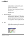
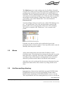
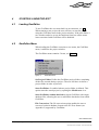


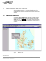

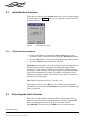
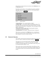
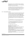
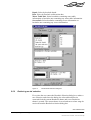

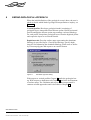

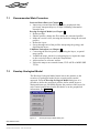

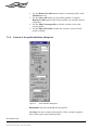
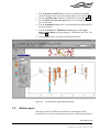
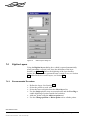
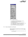

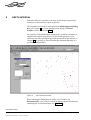
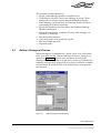

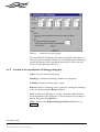


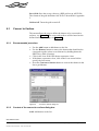


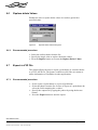
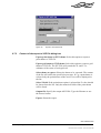
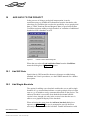


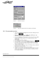
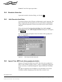


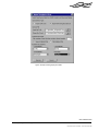
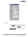
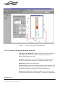


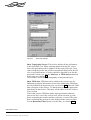
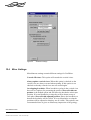
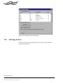


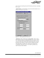
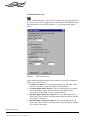
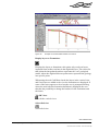
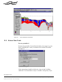
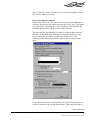


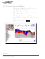

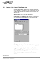


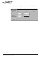


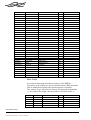
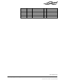

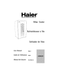
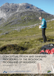

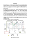


![User manual [ENG] - VegaObs Database Consultation Software](http://vs1.manualzilla.com/store/data/005911546_1-f613e0852217e54ec3af6f546af45374-150x150.png)