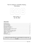
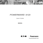
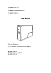
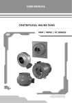
1
Charge Controller Manual
Approval:
Document #: 0102M01
Date: June ’07
REV : 1.2
Page 1 of 17
Registration Number 2006/005438/07
VAT Registration Number 4870231406
Tel: +27 (0)41 401 2500
Website: www.kestrelwind.co.za
Kestrel Voltage
Limiter
Type 0702
User Manual
Revision 1.1 (04-08)
Revision 1.0
(12-07)
For the following models of type 0702 voltage limiter
Type 0702-1000-135 (e300i-009-110)
Type 0702-1000-280 (e300i-009-200)
1000W 10A
1000W 4A
Voltage Limiter Manual
Approval:
Document #: 0702M001
Date: April ‘08
REV : 1.1
Page 2 of 17
CONTENTS
PAGE
1
Safety Considerations
1.1
1.2
1.3
1.4
2
4
4
4
Components Supplied
Components not Supplied
Tools Required
Unpacking
5
5
5
5
Installation Instructions
4.1
4.2
4.3
4.4
5
Voltage Limiter Description
Identification and Markings
Applications and uses
Voltage Limiter Assembly
3.1
3.2
3.3
3.4
4
3
3
3
3
Voltage Limiter Overview
2.1
2.2
2.3
3
Mechanical Safety
Electrical Safety
Installation Hazards
Operational Safety
Typical Installation Example
Mounting the Voltage Limiter
Electrical Wiring
Securing
Securing the Voltage Limiter
6
7
8
9
Wire and Cable Sizes
Sizes
5.1
5.2
5.3
Wind Turbine Wiring
Lightning Protection
Wire Tables
10
10
10
0
1
11
11
6
Technical Specifications
12
12
7
Trouble Shooting
13
13
8
Maintenance
14
14
9
Warranty Conditions
14
14
10 Customer Feedback
17
17
Voltage Limiter Manual
Approval:
Document #: 0702M001
Date: April ‘08
REV : 1.1
Page 3 of 17
Disclaimer
Kestrel Wind Turbines makes every effort to give accurate information in this manual and is in no
way liable for any error or omission. The user of this manual assumes full responsibility and risk.
We appeal to your common sense to read and apply the safety notes. Consult professional
engineers and take advice if you are unsure.
1 Safety Considerations
1 SAFETY FIRST
1.1
1.2
1.3
1.4
Mechanical Safety
Electrical Safety
Installation Hazards
Operational Safety
Although Kestrel Voltage Limiters are designed with your safety in mind, accidents can easily occur
and there are always inherent dangers associated with any type of machine. Consult installation
professionals if you lack experience or confidence.
1.1 Mechanical Safety
Use good handling methods and take precautions to avoid physical injury during installation and
maintenance/repair procedures. Be responsible when using all tools whether manual or powered.
1.2 Electrical Safety
Read and adhere to the installation instructions for this product. Do not work on the system when the
wind turbine is running or when lightning is possible.
Disconnecting and re-connecting wires may cause a spark and the presence of explosive hydrogen
from battery charging is always a possibility. Adequate ventilation must be provided for battery
installations. The wire size used for connections must be correct for the powers supplied. The smaller
the wire diameter, the higher the wire losses and therefore the heat generated in the wire. Use
correct wire sizes throughout the installation. The amount of energy stored in a battery is
considerable and fire can result from shorts. Fit a suitable fuse or circuit breaker in the battery cable.
In general, respect the system and use common sense. Consult a qualified electrician if you are unsure.
1.3 Installation Hazards
Be sure to read and adhere to the installation instructions for this product. Always work carefully and
have an assistant wherever possible. Always re-check the work as you progress. Slack bolts, poor
workmanship and loose electrical connections must be avoided.
1.4 Operational Safety
Be aware that the voltage limiter will become hot during certain operation modes. This is quite
normal but be aware of high temperatures on the rear heatsink. System checks are best carried
out in calm weather conditions. Avoid any maintenance or inspection during windy weather. Be
aware that internal voltages can cause a shock.
3
2 Voltage Limiter Overview
2 VOLTAGE LIMITER OVERVIEW
2.1 Voltage Limiter Description
2.1 Voltage Limiter Description
2.2 Identification and Markings
2.3 Application and Uses
Voltage Limiter Manual
Approval:
Document #: 0702M001
Date: April ‘08
REV : 1.1
Page 4 of 17
IMPORTANT: This product is not designed to be used on a Kestrel Battery-charging system.
The Voltage Limiter is solely to restrict the output voltage of a Kestrel wind turbine in Grid Tie
applications and hybrid applications using an Outback MX60.
Sustainable/renewable energy sources such as wind turbines and hydro-generators are often
connected to a charge controller or a Grid Tie inverter. Such components can exhibit operational
modes that reduce the demand or disconnect the system from the generator. Any operational
generator or alternator will exhibit high output voltages when no output is demanded.
The Kestrel Type 0702 Voltage Limiter uses electronic means to restrict the incoming voltage at a
pre-designed value. The product uses linear technology causing no electrical disturbance during
operation. This quality is paramount when powering any communication or computer equipment.
The Voltage Limiter is passive and uses no energy whatsoever during normal operation. If for any
reason the generator voltage rises, the limiter restricts this voltage rise to a preset value. It
achieves this limiting by loading the generator. The product is housed in a steel enclosure for wall
mounting. It is extremely reliable in operation and incorporates a failsafe design. Unit cooling is
achieved by convection and three assisting fans.
2.2 Identification and Markings
Removing the front cover reveals the product rating plate; if the Voltage Limiter does not carry
this stamp it does not carry a Kestrel warranty and may not be authentic. A connection diagram is
adhered inside the cover.
*NOTE: Product Rating label example (above) is for format only, specifications do not apply
2.3 Applications and Uses
The Kestrel Voltage Limiter Type 0702 is primarily intended for use with the e300i (1kW) Kestrel
wind turbine that has either been installed with an in-line battery charge controller such as the
Outback MX60 or a Grid Tie inverter. Each application may require specific additional electrical
equipment. Consult the manuals supplied with this equipment.
4
Voltage Limiter Manual
Approval:
REV : 1.1
Document #: 0702M001
Date: April ‘08
Page 5 of 17
3 Voltage Limiter Assembly
3 VOLTAGE LIMITER ASSEMBLY
3.1
3.2
3.3
3.4
Components Supplied
Components Not Supplied
Tools Required
Unpacking
3.1 Components Supplied
The following components are supplied:
Voltage Limiter assembly
Steel Wall Hanger
3.2 Components Not Supplied
The following components are necessary to complete an
installation:
Electrical crimp terminals
Wall fixing screws or bolts
20mm cable glands
3.3
3.3 Tools Required
The following hand tools are required for the charge controller installation:
Small size electrical screwdriver
Medium size electrical screwdriver
Wire strippers for electrical connections
Electrical crimping pliers
Tape measure for positioning
Spirit Level (Optional)
Hand drill and suitable drill bits
3.4
3.4 Unpacking
Open the packaging container and check for any transit damage. The parts contained are listed
in section 3.1 and on the included packing slip. Lay out and identify the parts.
5
Voltage Limiter Manual
Approval:
REV : 1.1
Document #: 0702M001
Date: April ‘08
Page 6 of 17
4 Installation Instructions
4 INSTALLATION INSTRUCTIONS
4.1 Typical Installation Example
4.1
4.2
4.3
4.4
Typical Installation Example
Mounting the Voltage Limiter
Electrical Wiring
Securing the Voltage Limiter
A typical battery charging installation is shown below. The system comprises an e300i (1kW)
Kestrel wind turbine, voltage limiter, alternative charge controller and storage battery. Note that
other electrical equipment will be required to comply with local installation requirements.
A typical Grid Tie installation is shown below. The system comprises an e300i (1kW) Kestrel wind
turbine, voltage limiter and an alternative manufacture Grid Tie inverter. Note that other electrical
equipment will be required to comply with local installation requirements.
Consult the Grid Tie inverter and charge controller manuals for full installation procedures.
6
Voltage Limiter Manual
Approval:
Document #: 0702M001
Date: April ‘08
REV : 1.1
Page 7 of 17
4.2 Mounting the Voltage Limiter
The Kestrel Voltage Limiter Type 0702 is only suitable for indoor installation.
The unit must be vertically mounted using the wall hanger supplied. Fix the
wall hanger using secure fastening with suitable wall plugs or bolts. Check
that a minimum of 100mm (4”) space all around the unit for cooling.
Do not place any objects on the top of the enclosure. The unit relies on
the free passage of air through the heat sink for cooling.
NOTE: The Voltage Limiter uses cooling fans. Make sure that the bottom air entry is kept free
of obstructions. Unit cooling relies on the free passage of air through the cabinet.
Check again that the wall hanger is secure to the fixing surface. Now raise the voltage limiter and
clip the upper rear angle on to the wall hanger. Centre the limiter and fit the single bottom fixing
screw through the limiter enclosure, screwing it fast into the wall hanger.
7
Voltage Limiter Manual
Approval:
Document #: 0702M001
Date: April ‘08
REV : 1.1
Page 8 of 17
4.3
4.3 Electrical Wiring
Observe the Polarity at all times. Only connect +VE RED cables to +VE RED terminals and -VE
BLACK cables to -VE BLACK terminals. Otherwise, equipment damage may result and any
warranty will be invalidated.
8
Voltage Limiter Manual
Approval:
Document #: 0702M001
Date: April ‘08
REV : 1.1
Page 9 of 17
PLEASE FOLLOW THE INSTRUCTIONS BELOW !
CONSULT SECTION 5 FOR WIRE SIZE RECOMMENDATIONS
The Voltage Limiter is provided with two pairs of +VE and -VE clearly marked terminals for "TURBINE"
and "OUTPUT" at the bottom of the regulator. The TURBINE BRAKE switch is designated “S1” and the
OUTPUT CIRCUIT BREAKER is designated “Q1”. The turbine brake switch stops the turbine by creating
an electrical short on the turbine input. When operated, this prevents high turbine open circuit voltages
being developed.
The wind turbine should not be rotating during this installation. If turbine access is not
possible, short the two turbine power wires together. Observe the Polarity at all times. Only
connect +VE RED cables to +VE RED terminals and -VE BLACK cables to -VE BLACK terminals.
ONLY THE RIGHT FRONT PANEL IS REMOVED FOR INSTALLATION.
a) Arrange the wires from the turbine and the battery ready for connection.
b) Check that the turbine wires are shorted. Check that the output wires are isolated from the
charge controller or Grid Tie inverter.
c) Check that the Voltage Limiter OUTPUT CIRCUIT BREAKER (Q1) is switched OFF and that the
TURBINE BRAKE SWITCH (S1) is switched ON.
d) Connect the output wires to the Voltage Limiter output terminals +VE and –VE observing
polarity.
e) Connect an electrical earth wire to the marked earth screw terminal provided.
f) Separate the turbine wires and connect the turbine negative wire to the Voltage Limiter
negative terminal. You may have to improvise by maintaining a short on the turbine wires as
this connection is made.
g) Finally connect the turbine positive wire to the Voltage Limiter positive terminal.
h) Check that the turbine brake switch “S1” is ON and that the output circuit breaker “Q1” is off.
(There is no reaction)
i)
Complete the external wiring to the charge controller or Grid Tie inverter. Follow the
manufacturer’s instructions for this work. Only after all wiring is complete and secure, the
Voltage Limiter output circuit breaker may be switched on and the turbine brake switch
switched off. Switch the turbine switch OFF.
The instructions are reversed for de-commissioning. First isolate the additional equipment,
switch the Voltage Limiter output breaker OFF and then operate the turbine brake switch.
A disconnected turbine should always be shorted.
4.4 Securing the Voltage Limiter
Always switch the turbine brake on (S1 ON) and the output circuit breaker off (Q1 OFF)
before any maintenance or service
Remember to re-fit all covers and guards on all equipment installed before switching on.
NOTE: The Voltage Limiter controls high voltages and the internal components can cause a
shock hazard. Be aware and consult a professional if you are in any way unsure.
9
Voltage Limiter Manual
Approval:
REV : 1.1
Document #: 0702M001
Date: April ‘08
Page 10 of 17
5 Wire and Cable Sizes
5 WIRE
WIRE AND CABLE SIZES
SIZES
5.1
5.2
5.3
Wind Turbine Wiring
Lightning Protection
Wire Tables
5.1 Wind Turbine Wiring
Kestrel wind turbines produce dc power and output on two double insulated output wires (tails).
The RED wire is POSITIVE and the BLACK wire is NEGATIVE.
Observe the Polarity at all times. Only connect +VE RED cables to +VE RED terminals and -VE
BLACK cables to -VE BLACK terminals. Otherwise, equipment damage may result and any
warranty will be invalidated.
The following suggestions are made as a guideline. If you are in doubt, consult an electrician.
The output wires must be extended as required for the installation. Choose the wire size that is
suggested for the size of turbine, electrical current and the distance from the turbine to the charge
controller. Good wire connections are absolutely essential to avoid poor power delivery and high
temperatures at the connection.
All electrical systems lose energy because cables have a resistance. The mounting structure must be
directly earthed for lightning. The power cable is usually brought down the inside of the mounting
structure to give some protection. Supply cables should never be spanned or suspended from the
turbine structure and should be buried at least one half metre deep in a suitable plastic or steel
conduit.
5.2
5.2 Lightning protection
Proper grounding is essential to protect the system from induced voltages and static. The
installation must comply with local requirements for electrical installations. Ensure that the
generator is electrically connected to the mounting structure and that the structure is earthed. This
is usually done by burying a 2 to 3m (6’ – 10’) length of water pipe (steel or copper) horizontally,
800mm (2,5’) below the ground surface. A good connection is made between the middle of the
pipe and the structure. An improved method is to bury a cross of pipe, which requires an "X"
shape to be excavated. The connection is made in the centre of the cross.
The negative battery connection should also be grounded using a ground point close to the
battery. The wire size for grounding should be the same size as the power cables. Commercial
lightning arrestors are available at electrical stores and can be fitted at the bottom of the
structure or pole or at the regulator input.
10
Voltage Limiter Manual
Approval:
REV : 1.1
Document #: 0702M001
Date: April ‘08
Page 11 of 17
5.3 Wire Tables
The copper wire sizes given in the tables are calculated for 3% power loss in wire resistance. This
is usually acceptable in low voltage installations. A larger wire size will increase the delivered
power but usually a compromise is reached as larger cables cost more. It is recommended that the
wire sizes given be taken as a minimum value. Measure the distance from the top of your structure
(i.e. the e150) to the regulator. Select the wire size for that distance from the table. The double
run of +ve and -ve is already accounted for.
The power cable should be run down the inside of the pole or structure and then buried in a
suitable underground conduit at least 500mm below the ground surface.
Wire lengths account for a double cable run (both +ve and –ve together) being given in
metric metres (m) and imperial feet (‘). Wire cross sectional area is given in metric
square millimetres (sq mm) and American Wire Gauge AWG.
Wire Size for e220 200V (4A maximum current)
20m (66’)
40m (130’)
60m (200’)
80m(260’)
100m (330’)
0,5sq mm (20)
0,8sq mm (18)
1,5sq mm (16)
1,5sq mm (16)
2,0sq mm(14)
Wire Size for e300i 110V (12A maximum current)
10m (33’)
20m (66’)
30m (96’)
10sq mm (7)
20sq mm (4)
35sq mm (2)
40m (130’)
35sq mm (1)
50m (165’)
50sq mm (0)
80m(260’)
70sq mm (00)
100m (330’)
100sqmm(0000)
Wire Size for e300i 200V (6A maximum current)
20m (66’)
40m (130’)
60m (200’)
80m(260’)
100m (330’)
0,65sq mm (19)
1,5sq mm (16)
2sq mm (14)
2,5sq mm (13)
3,5sq mm(12)
11
Voltage Limiter Manual
Approval:
Document #: 0702M001
Date: April ‘08
REV : 1.1
Page 12 of 17
6 TECHNICAL SPECIFICATIONS
General: Linear controlled voltage limiter to telecommunication specification with 800 and
1000W capability for the over-voltage protection of suitable series connected charge
controllers and grid tie inverters. Supplied to order for system voltages of 110Vdc and
200Vdc.
Controller Model
Type 0702-1000-135
Type 0702-1000-280
Input voltage and variation
Efficiency
Rated Power
Maximum Current
1000W
1000W
10A
4A
110Vdc nominal (135Vdc)
200Vdc nominal (280Vdc)
(0-400Vdc)
(0-800Vdc)
>99% at full load
Input frequency
Input power factor
N/A dc input
N/A dc input
Output Voltage (135Vdc) Factory set (no user adjustment)
Output Voltage (245Vdc) Factory set (no user adjustment)
135 - 126Vdc
280 - 245Vdc
Output voltage ripple
Output voltage regulation
N/A
+8% - 2%
User control
Turbine brake and output isolate/circuit breaker
User controls external
None
LED Indication
None
Cooling
Natural Convection with fan assist
Maximum Ambient
40°C
Weight
30kg
IP Rating
IP35
Cabinet Dimensions (wall mounting)
Certification
500Wx620Hx300D
Complies with EMC requirements CIS22 Class B
12
Voltage Limiter Manual
Approval:
Document #: 0702M001
Date: April ‘08
REV : 1.1
Page 13 of 17
7 TROUBLE SHOOTING
THE KESTREL TYPE 0702 VOLTAGE LIMITER MAY BE SERIOUSLY DAMAGED FROM POLARITY
REVERSAL (wrong connection of +ve and –ve wiring). VOLTAGE LIMITER DEGRADATION
CAN OCCUR FROM IMPROPER INSTALLATION CAUSING OVERHEATING.
IF FOR ANY REASON THE WIND TURBINE IS DISCONNECTED, SHORT THE GENERATOR
OUTPUT WIRES. THIS WILL LOAD THE GENERATOR AND MINIMISE ROTATION.
Q
The cooling fans never switch on.
A
The turbine stop switch is ON. The fans are automatic and only operate when voltage
limiting occurs.
Q
The Output circuit breaker trips.
A
There is a fault on the output cables. The output cables are reversed.
Q
The Voltage Limiter is always working at a high temperature.
A
The unit is diverting energy. The output circuit breaker has tripped. The charge controller or
inverter has failed. The mains have failed (inverter only). Internal limiter components have
failed.
Q
Will I damage the Voltage Limiter if I disconnect the charge controller or the inverter?
A
No, the Voltage Limiter will continue to control with nothing connected. It may however
become quite hot as it has to divert all the energy from the wind turbine. It is best to
operate the turbine stop switch rather than have the controller working so hard for no
reason.
13
Voltage Limiter Manual
Approval:
Document #: 0702M001
Date: April ‘08
REV : 1.1
Page 14 of 17
8 MAINTENANCE
The Kestrel Type 0702 Voltage Limiter is designed for continuous operation on 100% duty cycle
and requires no regular part replacement. Keep the unit clean and ensure that no foreign objects
reduce the airflow through the bottom inlet grill or the top front outlet. Clean the case only with a
soft damp cloth. Do not use any form of solvent.
This product controls and limits voltages that can cause a shock. Always take extreme care when
the cover is removed. In the unlikely event of failure, the unit should be returned to the dealer or
direct to the factory for repairs.
9 WARRANTY CONDITIONS
Kestrel’s wind turbines and voltage limiters are manufactured to the highest standards, in
accordance with Kestrel Wind Turbines’ standard and quality specifications, and warrants that the
voltage limiter is in good working order upon delivery and for a period of 24 months. Warranty
terms and conditions are outlined below.
1.
Eveready warrants that Limiters will, on delivery, be free of defects in design, material and
workmanship and will be fit for their intended purpose for a period of two years calculated from the
date of installation, subject to proper installation, maintenance and use in accordance with the User
Manual.
2.
This warranty is further subject to the Customer returning the defective Limiter at its cost to the
premises of Eveready within the warranty period and furnishing full details in writing of the alleged
defect.
3.
Eveready's obligations under this warranty shall be limited to the repair or replacement of defective
Limiters at its cost or to a refund to the Customer of the original cost thereof, as Eveready may
determine in its discretion. Eveready shall not be responsible for any damages suffered by the
Customer pursuant to any defects covered by this warranty.
4.
This warranty shall not apply to any damage to Limiters caused by winds exceeding 160 kilometres
per hour or any other factors beyond the control of Eveready.
5.
The Customer may purchase an extended warranty from Eveready in respect of Limiters, subject to
Eveready's standard conditions.
14
Voltage Limiter Manual
Approval:
Document #: 0702M001
Date: April ‘08
REV : 1.1
Page 15 of 17
CONTACT KESTREL WIND TURBINES
Kestrel Wind Turbines
P.O. Box 3191
Eveready Diversified Products (Pty) Ltd
North End
Eveready Road
Port Elizabeth
Struandale
6056
North End
Eastern Cape
Port Elizabeth
Republic of South Africa
South Africa
Tel: +27 (0)41 401 2500
Email: [email protected]
Registration Number 2006/005438/07
VAT Registration Number 4870231406
Web: www.kestrelwind.co.za
15
Voltage Limiter Manual
Approval:
Document #: 0702M001
Date: April ‘08
REV : 1.1
Page 16 of 17
NOTES
16
Voltage Limiter Manual
Approval:
Document #: 0702M001
Date: April ‘08
REV : 1.1
Page 17 of 17
10 CUSTOMER FEEDBACK
Customer enquiry and feedback sheet
Customer
Customer Information
Customer Name:
Postal Address:
Serial Number:
Phone Number:
E-Mail Address:
Fax Number:
Enquiry Details
Complete the form and submit to Kestrel Wind Turbines. Your feedback and queries are valuable
to us.
Indicate your enquiry or feedback in the space provided below
For OFFICIAL Use Only
Date Replied:
Signature:
Comments:
17