1
AREM PRO, s.r.o.
Automation, regulation, measurement
158 00 Praha 5, Nové Butovice, Nušlova 2275/15,
tel/fax +420 251 621 228
Operation of the
Cnc886/Win Control
System
General Part
page 1
Operating of the Cnc886/Win general part, revision 7.12.2010
AREM PRO, s.r.o.
Automation, regulation, measurement
158 00 Praha 5, Nové Butovice, Nušlova 2275/15,
tel/fax +420 251 621 228
2005 AREM PRO, s.r.o.
4. revision, 7.12.2010
AREM PRO, s.r.o., Nušlova 2275/15, 155 00 Praha 5
tel/fax: +420 251 621 228
page 2
Operating of the Cnc886/Win general part, revision 7.12.2010
AREM PRO, s.r.o.
Automation, regulation, measurement
158 00 Praha 5, Nové Butovice, Nušlova 2275/15,
tel/fax +420 251 621 228
1. Content
1. Content .......................................................................................................... 3
2. Basic Information ......................................................................................... 6
2.1. System Security .................................................................................. 6
2.2. Touch Screen...................................................................................... 7
2.3. Keyboard and Mouse .......................................................................... 7
3. Standard System User Interface ................................................................. 8
3.2. Fingerboard......................................................................................... 9
3.3. Tab Auto ........................................................................................... 10
3.3.1. Axes position ......................................................................... 15
3.4. Tab Manual ....................................................................................... 17
3.4.1. Tab Manual Move .................................................................. 17
3.4.1.1. Position limits ............................................................. 19
3.4.2. Tab Manual Referencing ....................................................... 20
3.4.3. Tab Manual Functions ........................................................... 21
3.5. Tab Library ........................................................................................ 22
3.6. Tab Param ........................................................................................ 27
3.7. Tab Service ....................................................................................... 29
3.7.1. Tab Service Axes................................................................... 30
3.7.2. Tab Service Servos ............................................................... 32
3.7.3. Tab Service Binars ................................................................ 33
3.7.4. Tab Service Trends ............................................................... 34
3.8. Tab Errors ......................................................................................... 35
3.8.1. Other Information in Tab Errors ............................................. 36
3.9. Editor................................................................................................. 37
4. Manual Wheel AHW886 .............................................................................. 38
4.1. Basic Description .............................................................................. 38
4.2. Display of Cnc886 Situation .............................................................. 39
4.3. Display and Control while the Program is Running ........................... 39
4.4. Display and Control while the Program is Ready .............................. 40
4.4.1. Control of Automatic Mode .................................................... 41
4.4.2. Manual Mode of Wheel – Axis Selection ............................... 41
4.4.3. Step Selection mode.............................................................. 41
4.4.4. Axes rose mode..................................................................... 42
4.4.5. Wheel in Mode from Line and from Position.......................... 43
4.5. Safety at Work with Wheel................................................................ 43
5. Basic Activities ........................................................................................... 45
5.1. Statuses of System ........................................................................... 45
5.2. Switch-on of Power ........................................................................... 45
5.3. Referencing of Axes.......................................................................... 45
5.4. Manual Control of Axes and Spindle ................................................. 46
5.5. Manual Control of Functions ............................................................. 46
5.6. Loading of Technological Programs and their Administration ........... 46
5.7. Setting of Corrections and Parameters ............................................. 47
5.8. Confirmation of Error Message ......................................................... 47
page 3
Operating of the Cnc886/Win general part, revision 7.12.2010
AREM PRO, s.r.o.
Automation, regulation, measurement
158 00 Praha 5, Nové Butovice, Nušlova 2275/15,
tel/fax +420 251 621 228
5.9. Resetting of Error of Servo-amplifiers ...............................................47
5.10. Initiation of Technological Program .................................................48
5.10.1. Test of Program - Test .........................................................48
5.10.2. Measuring of Time of Program duration ..............................48
5.10.3. Initiation From Line or From Position ...................................48
5.10.4. Single-step Operation Mode - Step......................................49
5.10.5. Suspension of Program .......................................................49
5.10.6. Modification of Feed.............................................................49
5.10.7. Modification of Spindle Speed .............................................49
5.11. Stop of Technological Program .......................................................49
5.12. Working in Service Mode ................................................................50
5.13. Check and Setting of Licence..........................................................50
5.14. System Switch-off............................................................................50
6. More Information about the System ..........................................................51
6.1. System of coordinates and corrections .............................................51
6.2. R-parameters ....................................................................................53
6.3. Programs in Memory .........................................................................56
7. Programming Language Description ........................................................57
7.1. Program Structure .............................................................................57
7.1.1. First Line – Number and Name of Program ...........................57
7.1.2. Command Prompts ................................................................57
7.2. R parameters and MP parameters ....................................................59
7.2.1. Value......................................................................................60
7.2.2. Arithmetic Operations and Assignment Command ................60
7.3. Control of Program flow.....................................................................62
7.4. Unconditional Branch ........................................................................62
7.5. GOTO statement ...............................................................................62
7.5.1. Calling of Subprogram CALL and CALL% .............................62
7.6. Conditional Branch ............................................................................63
7.6.1. Conditional Go to in Program BN<line> R-Parameter............63
7.6.2. Structure IF THEN .................................................................63
7.7. ECHO Function .................................................................................64
7.8. WARNING Function ..........................................................................64
7.9. ERROR Function...............................................................................64
7.10. Special Function of System of Coordinates Transformation ...........65
7.11. Mirroring ..........................................................................................65
7.11.1. Change of Scale ..................................................................65
7.12. M-function........................................................................................65
7.12.1. Pre-defined M-functions.......................................................66
7.13. H-functions ......................................................................................66
7.13.1. Pre-defined H-functions .......................................................66
7.13.2. User H-functions ..................................................................66
7.14. D-functions ......................................................................................67
7.14.1. Pre-defined D-functions .......................................................67
7.14.2. User D-function ....................................................................67
7.15. T-word for Selection of Tool Correction...........................................67
7.16. Speeds ............................................................................................67
page 4
Operating of the Cnc886/Win general part, revision 7.12.2010
AREM PRO, s.r.o.
Automation, regulation, measurement
158 00 Praha 5, Nové Butovice, Nušlova 2275/15,
tel/fax +420 251 621 228
7.16.1. Feed F ................................................................................. 67
7.16.2. Linear Axes.......................................................................... 67
7.16.3. Rotating Axes ...................................................................... 68
7.17. Speed of Rotation S ........................................................................ 68
7.18. G-function........................................................................................ 68
7.18.1. Group 1: Interpolation .......................................................... 69
7.18.1.1. G0 Shift by Fast Feed .............................................. 69
7.18.1.2. Linear Interpolation G1............................................. 69
7.18.1.3. Circular Interpolations G2 and G3............................ 69
7.18.2. Group 2: Waiting.................................................................. 70
7.18.2.1. Delay Period (TI) ...................................................... 70
7.18.3. Group 3: Selection of Level G17 and G18 and G19 ............ 70
7.18.4. Group 4: Compensation....................................................... 70
7.18.5. Group 5: Shifting of the starting point .................................. 71
7.18.6. Group 6: G92 and G93 New Position .................................. 71
7.18.7. Group 7: Speed Characteristics G60 G64 ........................... 72
7.18.8. Group 8: Absolute Position G11 .......................................... 73
7.18.9. Group 9: Measuring of Distance - Absolute/Incremental ..... 73
7.19. Summary of G - words .................................................................... 74
7.20. Summary of M - words .................................................................... 75
7.21. Summary of H - words .................................................................... 75
7.22. Summary of D - words .................................................................... 75
page 5
Operating of the Cnc886/Win general part, revision 7.12.2010
AREM PRO, s.r.o.
Automation, regulation, measurement
158 00 Praha 5, Nové Butovice, Nušlova 2275/15,
tel/fax +420 251 621 228
2. Basic Information
Cnc886/Win Control System is industrial computer based system equipped with a
supplementary CAN bus.
Cnc886/Win Control System is operated in Windows operation system, to which RTX
real time upgrade, made by Ardence (former VentureCom), was installed. The
philosophy of the control program, built on Windows basis, brings many advantages.
One of them is possible cooperation with other programs in the control system
computer, such as CAD/CAM systems, production control programs, workshop
programming software etc. Another advantage is its functioning in all peripheries
ensured by the operation system, functionality of all Windows system net services and
last but not least a guaranteed growth of future performance of the control system as
well. The Windows system further brings many interesting program technologies, which
Cnc886/Win utilizes or plans to utilize for improvement of graphical user interface.
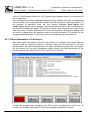
You can see a standard user interface of the Windows system after you switch the
computer on. An icon, which allows you to initiate the Cnc886 program, is prepared on
your desktop. After the initiation the application carries out many preparatory
operations. Their course depends to a large extent on the state of the Windows system;
therefore the initiation may take even several tens of seconds. First of all, after the
initiation and start-up of the program the processes connected with login of the
computer in the network are in progress in the Windows system. These processes
disable initiation of Cnc886 and initiation of other applications as well. You just have to
wait.
After the initiation of Cnc886 a window creating graphic interface of the
program appears. Most of operations are being carried out in a usual
manner. You just have to point to the object by the mouse and click on the
left mouse button to activate it. Or click on the window with the text and you
can change the text by means of the keyboard. An overwhelming majority
of such operations is entirely standard and the operations are respected by
the Cnc886 system.
The graphic user interface of Cnc886 system is variable. Various types of control
applications require various graphic processing and sets of functions easy accessible
from the interface. At the creation of these variants we have set out the following way.
The Cnc886 program has its standard interface, which is further described in this
general part of the system operation description. The standard interface is in some
applications supplemented with additional windows or it is completely replaced by them.
The standard interface is in case of “complete replacement” minimized in the menu bar
and it is prepared for use. Less frequent operations may be left out in the specialized
interface, because they remain accessible within the scope of standard interface. All
graphic interfaces are applicable concurrently; therefore there is no need to switch of
the current interface to be able to use the other.
2.1. System Security
Except advantages the utilization of Windows operation system brings certain risks as
well. Thanks to its spread the system is often the target of hackers’ attacks. The system
further lures to installation of new and new applications. This brings a danger of control
page 6
Operating of the Cnc886/Win general part, revision 7.12.2010
AREM PRO, s.r.o.
Automation, regulation, measurement
158 00 Praha 5, Nové Butovice, Nušlova 2275/15,
tel/fax +420 251 621 228
program collision with newly installed applications. Therefore it is strictly necessary to
observe following rules:
• No programs, drivers, or program patches may be installed on the control
computer without awareness and consent of the control system supplier. Failing
that, it is not possible to guarantee the correct functioning of the control program.
• Programs or scripts, which are not locally installed, must not be initiated in the
control computer. It means, programs on diskettes, CDs or net and other
possible data medium must not be run.
• The firewall must not be switched off.
Windows system is being delivered on the assumption of your consent with the licence
contract with the end user (EULA). If you do not agree with the contract, you are not
entitled to use the control system. Conditions of the guarantee, given by the EULA
contract (article 8), naturally feature in the guarantee conditions of the control system
as the whole and thus they are equal.
2.2. Touch Screen
Cnc886/Win system may be equipped by a touch screen. The touch screen is a
combination of the display and the input device. Finger touch or touch by other objects
invokes the same response as pointing by the mouse on the position and pushing its
left button. Holding the finger on the screen equals to holding the mouse button. It
means that you do not have to use the mouse at the common operation at all. The only
limitation of the touch screen is that it does not usually allow operations accessible
thought the right mouse button. However, you shall probably not need such operations.
Before you shall get used to the touch screen, be careful when you try to explain
another person something and point to the screen. One is often used to touch the
display and to tap it by the finger. The touch screen shall perceive such touches as
commands!
2.3. Keyboard and Mouse
It would be possible to design the entire system completely without the board and the
mouse and to solve everything by the touch screen. However, the practice has shown
that entering of numbers, editing of files and many other operations became too much
cumbrous. Therefore the keyboard and sometimes also the mouse were retained. The
mouse and the touch screen work together. The same task may be carried out either by
touching the screen or by clicking the mouse.
page 7
Operating of the Cnc886/Win general part, revision 7.12.2010
AREM PRO, s.r.o.
Automation, regulation, measurement
158 00 Praha 5, Nové Butovice, Nušlova 2275/15,
tel/fax +420 251 621 228
3. Standard System User Interface
Standard system user interface is divided to three basic segments.
• Status window
• Cards with tabs
• Fingerboard
The status window is located in the right upper angle of the system screen. It is always
visible.
Cards with tabs fill up the main part of the screen surface. They resemble filing cards
ordered in blocks, from which tabs with descriptions of cards “stick out” on the top. By
clicking (by the finger or the mouse) on the tab the card comes forth. Some cards
contain further system of subordinate cards with tabs.
The fingerboard is in the bottom part of the screen and it is always accessible.
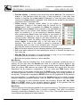
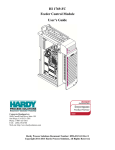
3.1. Status Window
The status window displays the current state of the system
by yellow letters. If you want to carry out some operation
and it does not work as you expected, the problem may lie
in the fact that the system status does not allow it. In such
case, you should pay the attention to this window. Here the sign “Error” appears in case
of an error.
page 8
Operating of the Cnc886/Win general part, revision 7.12.2010
AREM PRO, s.r.o.
Automation, regulation, measurement
158 00 Praha 5, Nové Butovice, Nušlova 2275/15,
tel/fax +420 251 621 228
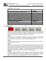
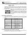
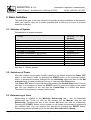
Possible status of the system:
Status
Power supply to the power part switched off
Initiation after switch-on the power part
The system is in order, some axis is not referred
Referring is in process
The system is ready, referred
Program is in process
Program suspended by M0 function
Program suspended by STOP button
Manual shift of axis is in process
Spindle started manually
Loading of the program is in process
Error state
Information in the
window
Power OFF
Initialising
Not referred
Referencing
Ready
Running
Stopped by M0
Stopped
Manual move
Manual bin
Loading: xxxxxxx
Error
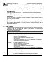
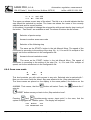
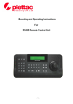
3.2. Fingerboard
Along the bottom edge of the screen there is a panel with five buttons. The buttons may
have various functions according to activities of respective tabs. Buttons change their
color according to their statuses; they behave like back-lighted buttons. They may be
pressed or unpressed and lighting or unlighting at the same time.
RESET
This button serves for stopping the operation in process – program run, referencing,
manual operation of spindle etc. If the light is red, it signalizes that the machine is idle.
If it does not light, the machine is in one of following operation modes.
STARTThis button serves for initiation of manual movements of axes to the back. The light is
yellow when the axis moves.
SPEED
This button is used for reduction of fast feed speed invoked by G0 function. All fast
feeds are slowed down ten times at the activation of this button. Repeated pressing the
button abolishes reduction of the speed. If the reduction of speed is switched-on, the
button is white back-lighted. Reduction of speed is particularly suitable at the tuning of
technological programs. It provides the operating personnel with time in case of
threatening collision of the machine with objects in the working area
START+
This button serves for initiation of manual movements of axes forward and for initiation
of program operation and for recovery of program operation after suspension by M0
function or STOP button. The light is yellow at manual moving and at automatic
operation of the program unless suspended by M0 function or STOP button
page 9
Operating of the Cnc886/Win general part, revision 7.12.2010
AREM PRO, s.r.o.
Automation, regulation, measurement
158 00 Praha 5, Nové Butovice, Nušlova 2275/15,
tel/fax +420 251 621 228
STOP
This button serves for suspension of running program. The light is red when the
program was suspended (stopped) and it waits until the START+ button is pressed.
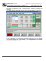
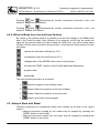
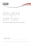
3.3. Tab Auto
Axes
Tab Auto serves for technological program monitoring and control. Information on
statuses of individual axes takes the largest space. Number and names of axes vary
according to the type of the machine. In case of our sample it is a system with six axes
named X, Y, Z, C, A, and V. Data on current position, number and value of tool
corrections (column Tool), data on value of shifting of the system of coordinates
(column Off. Gxx), and data on value of shift caused by G92 function (column Offset)
are displayed in the table (see 3.3.1 Image of Position). More on the meaning of
individual data you can find in the Chapter 6.1 System of Coordinates and Corrections.
The last line shows the status data InP (In Position), which signalizes conformity of
required position with real and tolerated deviation set by the supplier. The sign changes
during the machine operation. When idle, it should be always in status Yes. If not, the
system shall evaluate an error. The standard interface was designed for no more than
five imagined axes. If the system has more than five axes, it is possible to call the
menu, which offers names of all axes in the system by clicking the right mouse button in
the field. Now you can select, which axis you want to display in the line.
page 10
Operating of the Cnc886/Win general part, revision 7.12.2010
AREM PRO, s.r.o.
Automation, regulation, measurement
158 00 Praha 5, Nové Butovice, Nušlova 2275/15,
tel/fax +420 251 621 228
The last line of the table is Length, which serves for displaying the radius correction or
length correction. By clicking on the Length sign you switch between these two
corrections. The sign Length changes at the displaying of radius correction to Radius.
page 11
Operating of the Cnc886/Win general part, revision 7.12.2010
AREM PRO, s.r.o.
Automation, regulation, measurement
158 00 Praha 5, Nové Butovice, Nušlova 2275/15,
tel/fax +420 251 621 228
Mode
On the right from the table of axes there is a box with sign Mode. Under this sign there
is a roll-out menu, which allows you to select the desired mode.
Normal
If Normal is active, the run of the entire program shall be started after pressing the
START+ button.
Test
If Test is active, the check of the entire program shall be started after pressing the
START+ button. The system shall process the program, however without any
movements of axes and without the M function. Nevertheless, all corrections, shifting of
the starting point etc. shall be taken into consideration, so that if no program error
occurs, no error occurs at the real operation as well. Another result is that the
verification whether limits of axes are not exceeded and the dimensions of the resulting
work-piece are measured so it is possible to determine the size of the necessary semifinished product. These results are stated in the message in Errors tab.
From
In the From mode the program is tested only to the program line the number of which is
entered in the field under the Mode field. The program test shall stop at this line and
following lines are processed already in the normal mode, when axes are moving and
page 12
Operating of the Cnc886/Win general part, revision 7.12.2010
AREM PRO, s.r.o.
Automation, regulation, measurement
158 00 Praha 5, Nové Butovice, Nušlova 2275/15,
tel/fax +420 251 621 228
M functions are carried out. For a correct change between the test and the normal
mode the system shall offer all M functions which are active according to the program.
Some machines require based on their logic initiation of functions to initiate them before
pre-travel, some require their initiation after pre-travel. The selection shall be made by
the manufacturer and therefore the menu dialog may appear in other phase than
described below.
The Dialog shall offer a list of all M functions.
There are three options of choice:
• Yes
immediate realization of the offered function
• No
functions shall not be realized
• Reset the program is terminated
If you answer by selection of No, there is still an option to
start functions manually by means of some other method,
for example from tab 3.4.3 Tab Manual Function.
After answering to the dialog with menu of functions the system offers another action,
which is the pre-travel to the initial point. The coordinates are absolute.
Selection of Reset ends the program without movement.
After pressing the Start button (or START+) the
movement from the current position to the position at the
beginning of the program line, from which the
performance of the program was entered, is carried out.
The movement is carried out in the order of axes
determined by the producer. During the entire time of
movement the control system is in Stopped status, in
which it is allowed to carry out many operations, e.g. to
start or to switch off M functions. After its end the machine
stops in the status equal to the STOP button. It waits for
the START+ button for the continuation. Even in this moment, it means after completion
of the pre-travel, it is possible to start and switch off M functions. After pressing the
START+ button the program continues in the Normal mode.
Notes:
The track, on which the pre-travel shall be carried out, depends on the type of the
machine. In case of a five-axes cutter the following process is selected: C axis and A
axis are rotating first, then the pre-travel at X and Y axes is carried out and at the end at
Z axis. The pre-travel is carried out by the fast feed. If you are not sure about the
trajectory, on which the pre-travel is carried out, it is better to select the fast feed speed
limitation by means of SPEED button.
At the program operation a precise compliance of the row number with the preset value
is being tested. So, if the program does not contain the row with the number, the entire
program shall operate in the Test mode.
Time
If the Time mode is active a simulated run of the entire program including acceleration
and braking ramps, deceleration in dynamically problematic points etc. shall be started
by pressing the START+ button. The system is measuring the consumed time. The
time is running according to the processor performance approximately 30 up to 60
times faster than at the real program operation. The resulting time of the program
page 13
Operating of the Cnc886/Win general part, revision 7.12.2010
AREM PRO, s.r.o.
Automation, regulation, measurement
158 00 Praha 5, Nové Butovice, Nušlova 2275/15,
tel/fax +420 251 621 228
operation displayed in the field Duration is a very good estimation of program operation
time. Not only time of realization of M functions is in included in it. In case M functions
do not create an essential part of the program, the incorrect estimation is in order of
seconds even at programs lasting many hours. The measuring result is also recorded in
the Errors tab, in which the total run track and the average speed of feed are displayed.
FromPos
This mode is very similar to the From. However, the initial position is not entered by the
line number, but by the current position of the machine. The program shall be initiated
in simulated mode and checks the position of simulated passage with real position. If
the values conform (to the accuracy predefined by the manufacturer) the simulation
stops and the transition to normal mode is prepared the same way as in the From
This mode is permitted only with several types of machines.
Step
The Step button serves for switching the standard mode of the program operation and
step operation. If the step operation is selected, the button remains pressed in. Each
pressing changes the mode. The mode may be changed even during the operation of
the program if the program is suspended.
Duration
On the right from the table of axes is a field with the title Duration. In this field the time
of processing in hours minutes and seconds is being displayed while the program is in
operation. The information remains displayed even after termination of the program and
provides the information on the time of duration of the program initiated for the last
time.
Spindle
The row inscribed by the title Spindle serves for monitoring and adjustment of
operation of the spindle. In case of machines that do not have the spindle, the row is
either empty or it is used for control of some other type of equipment. Current speed in
revolutions/min is displayed in the red field. The positive value of speed conforms to the
M03 function – spindle forwards, the negative one conforms to M04 function – spindle
backwards. The left field displays the speed prescribed by the program. The remaining
part of the row serves for correction of revolutions/min. The left arrow reduced
revolutions by 10% steps; the right arrow increases revolutions by 10% steps. The
square 100% button cancels the correction. The current value of speed correction is
displayed between arrows. The correction may have values 0.50 up to 1.50.
If the machine has more spindles, it is possible to click on the field Spindle and to
switch cyclically between displays of individual spindles. The field with display of speed
adjustment coefficient which is individual for each spindle is changing as well.
Feed
The row prescribed by the title Feed serves for monitoring and adjustment of movement
speed. A current feed in mm/min is displayed in the green field. The field on the right
displays the feed prescribed by the program. The remaining part of the row serves for
feed override. The left arrow decreases the feed by 10% steps; the right arrow
increases the feed by 10% steps. After the speed is reduced to the value lower than 10
% the value is decreasing or increasing by 1 %. The 100 % button cancels the
correction. The current value of feed correction is displayed between arrows. The
page 14
Operating of the Cnc886/Win general part, revision 7.12.2010
AREM PRO, s.r.o.
Automation, regulation, measurement
158 00 Praha 5, Nové Butovice, Nušlova 2275/15,
tel/fax +420 251 621 228
correction may have values 0.00 up to 1.00. At the value of 0.00 the machine stops,
however the program operates! Repeated setting of non-zero correction restores the
feed.
Active M functions
Under the row Feed there is a field, in which active M functions are being displayed.
Active G functions
Another row is displayed at the program operation and active G function.
Active ECHO
Another row (empty in the sample) displays a text at the program operation written by
the ECHO program command.
Program lines
Last field of the tab displays part of the program, which is just being processed. The
line, which is being processed, is displayed as the first. After the stop in the Step mode
the completed row is displayed as the first and the row prepared for another step is
displayed as the second.
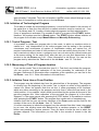
3.3.1. Axes position
The axis position is displayed based on the real value read from the servo-mechanism.
Therefore it may vary even in the idle condition of the machine. The system allows
selecting the way of position display.
There are five modes available:
page 15
Mode
Method of position value calculation
In program
The displayed value is the total of:
• positions reported by Irc servo sensor
• positions of the reference point
• manually preset offset of the coordinates system
• tool correction
• coordinates system offset G53 up to G59 set in terms of the program
• coordinates system offset set by G92
Corrected
The displayed value is the total of:
• positions reported by Irc servo sensor
• positions of the reference point
• manually preset offset of the coordinates system
• tool corrections
• coordinates system offset G53 up to G59 set in terms of the program
Absolute
The displayed value is the total of:
• position reported by Irc servo sensor
• positions of reference point
• manually preset offset of the coordinates system
Irc
The displayed value is a position reported by Irc servo sensor,
Operating of the Cnc886/Win general part, revision 7.12.2010
AREM PRO, s.r.o.
Automation, regulation, measurement
158 00 Praha 5, Nové Butovice, Nušlova 2275/15,
tel/fax +420 251 621 228
More about the meaning of modes of display see in 6.1 System of coordinates and
corrections.
The modes are being switched by using the roll-out menu and selection of the choice.
A form for displaying one more position is available in the Auto tab. It is the To end.
The difference between the current position of the coordinate and the end position
given by the just completed line of the CNC program is displayed in this mode. This
mode is not available in other tabs.
page 16
Operating of the Cnc886/Win general part, revision 7.12.2010
AREM PRO, s.r.o.
Automation, regulation, measurement
158 00 Praha 5, Nové Butovice, Nušlova 2275/15,
tel/fax +420 251 621 228
3.4. Tab Manual
Manual tab joins functions, which are being carried out manually by the operator. In this
mode the system has a limited option of verification of the correctness of realized
operations and the operator is responsible for their result.
3.4.1. Tab Manual Move
The tab Manual-Move has a table in its upper part for the display of the axes status and
an additional button Adjust (it may vary at some systems.
Under the table there is a row for the manual operation of the spindle and the row with
the four buttons for selection of manual movement speed.
The last row is determined for entering simple commands.
The Table of Axes
The table for display of axes status contains following columns:
• Sel - is the column of buttons by means of which it is possible to select the axis for
movement. The inside of the small box lights up as you can see as the example in
the X axis on the picture. When leaving the tab the selection automatically resets.
It is a certain safety measure, which prevents moving of axes by mistake. It may
sometimes cause a delay, however it minimizes the probability of damage.
• Axis – displays names of axes
page 17
Operating of the Cnc886/Win general part, revision 7.12.2010
AREM PRO, s.r.o.
Automation, regulation, measurement
158 00 Praha 5, Nové Butovice, Nušlova 2275/15,
tel/fax +420 251 621 228
• Position display – it abides by the same rules as the Auto tab. The exception is
display in final positions within the rage of axes movement. If the lower final
position is reached, the Lower Limit is displayed; in case the upper position is
reached the Upper Limit is displayed. Final positions are preset by the machine
constants in the configuration file.
• Offset displays manually preset offset of the system of
coordinates. Change of this preset shall be carried out by
Adjust button. After it is pressed, the Offset title changes to
NewAbsP and the Adjust button changes to the pair Done and
Clear. Items of the column shall become editable. You can
enter the position in it (in the meaning of Absolute display).
After pressing the Done button the shifting of the system of
coordinates is adjusted so that the system shall report the
current position Absolutely equal to the value preset by you.
The Clear button zeros the shifting. Change carried out by the
button Adjust is accessible only in the idle state of the
machine. The value of the offset is stored in reserved R
parameters and it is kept in the computer disc. Therefore it remains preserved
also after the system is switched of and switched on again.
• Ref is the status attribute of axis indicating whether the referencing took place.
• InP is the status attribute of axis indicating the state of In Position the same way
as in Auto tab
• NSt and PSt are statuses of end limit sensors in axes. In the Yes condition is
everything ok and the position is inside the limits.
• Err is the error status attribute of servo-amplifier.
Row Speed
The row starts with the indication box. If the spindle is manually initiated the box is
lighting. On the right from the Spindle title there is a field for current speed of the
spindle and besides this there is a box for preset spindle speed. Buttons DN and UP
allow the setting. DN reduces the speed, UP increases the speed with the pace
determined by the machine configuration. The row ends with FWD button, which
initiates rotation of the spindle forward and the RWD button, which initiates rotation of
the spindle rewards. Direction of revolutions may be changed also during operation of
the spindle. The spindle is stopped by RESET button on the fingerboard. If the machine
has more spindles, it is possible to click on the Spindle field and to switch cyclically
between displaying individual spindles. Also the fields with display of required speed,
which is individual for each individual spindle, are changing. Buttons UP, DN, FWD,
RWD and RESET relate to the currently selected spindle. If the machine has no
spindle, it is empty or it is used for control of another machine.
Row Feed
The four buttons allow changing speed of the manual movement. The speed for manual
movement is assigned to each axis in machine constants. This value is multiplied
according to selection of button by 10x, 1.0x, 0.1x or 0.01x. The selected speed and the
current speed are displayed in small windows.
page 18
Operating of the Cnc886/Win general part, revision 7.12.2010
AREM PRO, s.r.o.
Automation, regulation, measurement
158 00 Praha 5, Nové Butovice, Nušlova 2275/15,
tel/fax +420 251 621 228
Row for Command Entering
For manual pre-travel to a certain position or for machining of very simple shapes the
system allows entering a one-row command in CNC language syntax. Touching the
indication box of the text field activates the cursor and it is possible to edit the
command. It is possible to select the row by pressing the indication box – the same way
as the selection of individual axes. If the row is selected, it is possible to carry out the
command by pressing the START+ button. In this moment the system generates a
three-row program the first row of which is a heading, the second row represents the
command entered by you and the third one contains the M30 function for termination of
the program. This program is saved on disc under the name ManualCmd.cnc and it is
possible to activate it automatically and initiate it. After completion of work the system
takes your program out of the memory and activates the original program. However the
ManualCmd.cnc file remains on the disc.
Vector
For some machines, such as five-axes cutters, it is possible to activate the Vector menu
in the configuration file. It allows manual movement in the axis of the tool and this way
also moving the work-piece out when the program is interrupted etc. The item is
selected the same way as the movement in the individual axis and the movement is
initiated by buttons START+ (forward in the direction of the tool) or START- (backwards
in the direction of the tool). Calculation of the direction is tightly connected with the
mechanics of the machine instruction and it is carried out by the system.
Fingerboard
When opening the Manual Move tab, some buttons on the panel have rather different
functions:
START- If one of axes is selected (the indication box beside it is lighting), you may just
press the START- button, which initiates the backward movement in the given
axis. The movement shall be ended by releasing the button. Movement may
be initiated even when the spindle is running.
START+ If one of axes is selected (the indication box beside it is lighting), you may just
press the START+ button, which initiated the forward movement in the given
axis. Movement may be initiated even when the spindle is running. The
START+ button serves for initiation of the single-row command, provided it is
selected. It is not possible to start operation of the program in this tab.
3.4.1.1. Position limits
If axes are referred the system does not allow manual moving behind limits set by
machine constants. However, if the axis is not referred, the system is not able to
supervise final positions. In this situation the operator may run up to the emergency end
switches, which results in the error state. .
page 19
Operating of the Cnc886/Win general part, revision 7.12.2010
AREM PRO, s.r.o.
Automation, regulation, measurement
158 00 Praha 5, Nové Butovice, Nušlova 2275/15,
tel/fax +420 251 621 228
3.4.2. Tab Manual Referencing
Tab Manual-Referencing contains a table for display of axes status.
Table Axes
Display of axes status table contains following columns:
• Sel - is a column of buttons, by means of which an axis for referencing is
selected. The inside of the box is lighting at the selected axis. When leaving the
tab the selection automatically zeroes. It is a certain safety measure, which
prevents moving of axes by mistake. Sometimes it may cause a little delay,
however it minimizes the probability of damage.
• Axis – displays names of axes
• Abs position – displays position of the axis in the sense of Absolute mode. It is
not possible to switch the mode in the tab.
• Ref - is a status sign of axis indicating, whether the referencing was carried out.
• InP – is a status sign of axis indicating the In Position status, the same way as
in Auto tab.
• In1 and In2 – are statuses of sensors used for indication of reference positions
– which of sensors is used and how it depends on setting of servo-amplifier and
selection of referencing algorithm.
• NSt and PSt – are statuses of end limit sensors on axes. In yes status –
everything is ok and the position is inside the limits.
page 20
Operating of the Cnc886/Win general part, revision 7.12.2010
AREM PRO, s.r.o.
Automation, regulation, measurement
158 00 Praha 5, Nové Butovice, Nušlova 2275/15,
tel/fax +420 251 621 228
• Err – is an error state sign of servo-amplifier.
Item All
The tab Item All is prepared for facilitation of work. Its selection and pressing of the
START+ button initiates referencing of all axes in the order preset by the manufacturer.
Fingerboard
When opening the Manual-Referencing tab, some buttons on the fingerboard have
rather different functions:
START+ If some of axes is selected (the indication box is lighting), pressing the
START+ button initiates the referencing process.
RESET This button interrupts the referencing process. When the program is in
operation or the spindle is manually initiated, the operation is stopped.
3.4.3. Tab Manual Functions
Content of this tab is completely dependent on the particular machine. There are
placed buttons for various functions. Their number and the related reaction of the
system are changeable.
page 21
Operating of the Cnc886/Win general part, revision 7.12.2010
AREM PRO, s.r.o.
Automation, regulation, measurement
158 00 Praha 5, Nové Butovice, Nušlova 2275/15,
tel/fax +420 251 621 228
3.5. Tab Library
The Library tab serves for reading of programs from the disc or from the serial line to
the memory, saving to the disc, erasing from the memory and the disc, selection of the
program for initiation etc. The tab contains a window with list of files with programs on
the disc titled On disc, window with list of programs in the memory titled In memory
and window with view of the program selected for initiation (see below). Further there
are following buttons: Remove, Save as …, RS232, New …, Activate and New
directory …. Some buttons change their function and the title depending on the fact,
whether the selection of the program in memory or in the disc is active. All operations
may be carried out only when the machine is in idle status.
On disc
The window contains list of files with programs on the disc in the directory titled in the
headline of the window. The initial directory is determined by machine constants. It is
possible to go through the directory structure; however it is possible to realize
operations only in the initial directory and its subdirectories. The name of any of files or
directory is selected by clicking on the file or directory (its name is displayed in white on
grey background) and it is prepared for an action according to buttons.
For moving with the cursor inside the window you can easily use cursor keys of the
keyboard. It is particularly advantageous when going through the directory structure.
Point on the selected directory with the cursor and enter to it by means of ENTER key.
page 22
Operating of the Cnc886/Win general part, revision 7.12.2010
AREM PRO, s.r.o.
Automation, regulation, measurement
158 00 Praha 5, Nové Butovice, Nušlova 2275/15,
tel/fax +420 251 621 228
To leave the directory “one level above” you have to point to the item „[..]“ (Up Dir)
placed before the first subdirectory.
For quick searching of the file you may just press the initial letter of the file name. The
cursor automatically moves to the first file with the relevant initial character.
In memory
The window contains a list of programs loaded to the memory from the disc or from the
serial line. The loaded program has a number with % character included in the first row
and an optional text in parenthesis. This first row of the program is displayed in the
window In memory. The relevant item is selected by clicking on the item of the window;
(it appears in white on a grey background) and it is prepared for action according to
buttons.
Remove/Delete
The button allows removing the file or the directory from the
disc or from the memory according to the window of the
selected item. Erasing in the memory is carried out
immediately, erasing in the disc has to be first confirmed to
the system. The directory may be removed only if it is empty.
Save as …
The button Save as… allows to save the selected program on the disc under the
entered name. If the item In Memory is selected, the program saves from the memory,
if the item On disc is selected, the file saves from the disc. The dialog window with
notice for entering the name of the file with .cnc suffix appears in both cases. If you
change the suffix, you can not see the file in the window On disc! If you enter the name
of a file, which already exists, the system displays a question, whether you wish to
rewrite the file. If you enter a negative answer by means of the relevant button, the file
is not saved.
More>>
The More>> button allows loading of the program to the
memory from the serial line and from other sources.
After you select RS232, the system immediately starts
Loading: The status window displays number of loaded
characters. Now you can send the program from the connected computer. If you want
to cancel the operation, you should use the RESET button. After successful loading the
name of the program appears in the In Memory window and the statement appears in
the lower part of the window. At the same time the program is set as active, it means it
is prepared for initiation. If you want to save the loaded program in the disc, use the
option Save as…. This option used to be utilized mainly in the past and it remained in
the system. We suppose it will be deleted or replaced by something more useful.
New file/Edit
If the directory is selected or if the cursor is in the field In memory the button has title
New file… and it allows creation of a new file with the CNC program. If the selection
cursor is pointed on any file in the field On Disc, the button has title Edit. The button
Edit allows editing of the program on the disc. After its pressing the editor opens. More
information on the editor you can find in the independent chapter 3.9 Editor.
page 23
Operating of the Cnc886/Win general part, revision 7.12.2010
AREM PRO, s.r.o.
Automation, regulation, measurement
158 00 Praha 5, Nové Butovice, Nušlova 2275/15,
tel/fax +420 251 621 228
Load/Activate
The button activates the selected program; it means that it prepares it for running. In
case a file from disc is selected, the button is titled Load. It inputs the file to the
memory; it displays its name in the window In Memory and indicates it as prepared for
running. If a program with the same number already exists in the memory, an error is
displayed. If a program was selected in the window In Memory, it becomes active, it
means prepared for running. The active program is in the field In Memory marked by
crossed box.
New dir …
The button New dir… serves for creation of
subdirectory. A dialog window with question about
the name of the new directory appears. Further
progress is intuitive and it shall not surprise any
Windows user. It is ensured against cases of
incorrectly entered names, attempts to create
already existing directory etc.
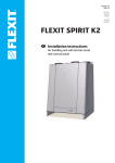
Window with View
The window with view serves for
display of the machine track.
This function is initiated by
clicking in the area of the
window. A white picture appears
on a black background, which in
selected axes displays the
machine trajectory. This function
is determined first of all for
orientation
in
technological
programs. At the display the control system goes through the entire program, the same
way as in the TEST mode.
(However it does not carry out
the check of exceeding the limit
positions). The time of the
program
running
through
depends on its length and
selected
value
of
the
interpolation step for the test,
which is defined by the
configuration file.
On the left from the window there is a set of buttons which serve for Zoom ( + and - ),
arrows for shifting of display and selection of axes (left upper arrow for vertical axis and
right lower for horizontal axis). The button in the middle is for setting the initial display
so that the accessible area of the machine in selected axes fits in the window. The
button in the left upper corner allows selection of the vertical axis and the button in the
right lower corner allows selection of the horizontal axis.
page 24
Operating of the Cnc886/Win general part, revision 7.12.2010
AREM PRO, s.r.o.
Automation, regulation, measurement
158 00 Praha 5, Nové Butovice, Nušlova 2275/15,
tel/fax +420 251 621 228
The current status of the tool position is displayed schematically even when the
program is running. When the program is running, it is not possible to use the button for
adjustment of display neither selection of axes.
The button “Full screen” above the button New dir… is available as well. It enlarges the
view to the entire display. Clicking to the area of the view returns you back to the
original display.
Trajectories made by the fast feed are differentiated by colors to ensure larger
transparency and further trajectories of tool point and trajectory of the point determining
final positions are differentiated as well. In the case shown on the picture there is a
work-piece marked by white color. However, the tracks of the rotating point and
machine tracks are relatively
complicated, and therefore the
work-piece is machined by a
five-axes system with a tool of
a certain length. Nevertheless,
these tracks are decisive in its
consequence in relation to fact
whether it is possible to operate
the program without exceeding
the limit positions of individual
axes.
page 25
Operating of the Cnc886/Win general part, revision 7.12.2010
AREM PRO, s.r.o.
Automation, regulation, measurement
158 00 Praha 5, Nové Butovice, Nušlova 2275/15,
tel/fax +420 251 621 228
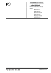
A similar situation, in which tracks of the tool point do not correspond to trajectories of
the machine, is utilization of radius corrections. On the picture you can see how an
unsuitable setting of the start of the system of coordinates, which leads to exceeding of
final positions, proves. Besides tracks also the outlines of the accessible machine area
in X and Z axes are displayed in the field of the view. The work-piece is inside the
rectangle; however the machine trajectories exceed the outlines.
Another aid is the button on the right from the “Entire Display”. It serves for switching
on and off the function for display of the cursor position. If the button is pressed in, the
position of the mouse cursor is displayed within the window of the display converted to
machine coordinates. This way it is possible to measure distances within the displayed
product.
Drag and drop
New versions of Cnc886 support drag and drop function. If you drag the file with CNC
code and drop it in the Library window, you do the same like selecting the file and use
Load button.
page 26
Operating of the Cnc886/Win general part, revision 7.12.2010
AREM PRO, s.r.o.
Automation, regulation, measurement
158 00 Praha 5, Nové Butovice, Nušlova 2275/15,
tel/fax +420 251 621 228
3.6. Tab Param
This tab serves for setting R parameters, tool corrections, and values for functions G53
up to G59. These parameters are particularly mentioned in chapter 6.2 R Parameters.
Settings of corrections and parameters are kept in the system even after leaving this
tab and saved in the hard disc and it is again loaded at the next start of the system, so
the operator finds it again in the same status. It often happens that the setting for
various programs significantly differs. Therefore there is an option to write setting of
selected parameters to a file and then to load it. Parameters, which are not mentioned
in the file, remain unchanged. Therefore it is possible to load even several files one
after another and combine their effect. Files with setting have suffix .par and they have
very simple format. It is a plain text file. Each row, which begins with the character of
percent % is understood as a commentary. Other rows must contain commands of
following type
R<parameter number> = <expression> ;
or
TOOL_COR[<tool number>,<correction name>] = < expression > ;
or they must be empty. Terminal semicolon is compulsory. The expression must be
entered in a usual manner with utilization of addition, subtraction, multiplication, and
division (signs + , - , * , / ) including the option to use brackets and selected
mathematical functions (more you can find in 7.2.2 Arithmetical operations and
page 27
Operating of the Cnc886/Win general part, revision 7.12.2010
AREM PRO, s.r.o.
Automation, regulation, measurement
158 00 Praha 5, Nové Butovice, Nušlova 2275/15,
tel/fax +420 251 621 228
commands statement). Elements of expressions are constants, or values of R
parameters. (see the following example).
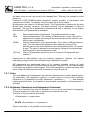
File example:
% -------Parameter file example-----%
% Program parameters
%
R3 = 182.4 ; R4 = 15 ;
R5 = (R4 + 3*R3)/25.4 ;
%
% Tool #1
%
TOOL_COR[ 1,X
] = 12.85 ;
TOOL_COR[ 1,Y
] = 50.00 ;
TOOL_COR[ 1,Z
] = 50.00 ;
TOOL_COR[ 1,Length] = 180.00 ;
%
% END
The area of the tab is created by three roll-out menus for setting parameters, tool
corrections, and offset functions G53 up to G59. In the right part there are tools for
administration of files with parameters, i.e. it is a window for selection of files and
buttons Edit, Save as…, Apply, Delete, Backup, and Open…. In the middle of the
lower part of the tab there is a row titled Cmd: for setting the parameter with command
and above it there is a window for log of commands.
R00-R09
Under the roll-out menu there is a list of twelve values of R parameters. Clicking on the
value places the cursor in the relevant row and the value may be adjusted by the
keyboard by entering the number or an expression. You can type for example 1.23, but
you can also type R0+10*(2+SIN(65)). You can use every line as a calculator. The
value is saved in the parameter by clicking on another object of the tab or by pressing
the Enter on keyboard. In the window for log of commands a record on realized change
appears. If the entered value was incorrect, the record is provided with an error sign ??.
Otherwise it is provided with sign OK. When unrolling the roll-out menu a selection of
another interval of displayed parameters is provided. Parameters in the range from R00
up to R102 may be adjusted. Further parameters may be set by means of a command
in the window Cmd:
Tool
Under the roll-out menu there is a statement of values of tool corrections in mm for the
relevant tool. In the row rad there is a radius correction; in the row len there is the
length correction.
Unrolling the roll-out menu you can choose other tools. In total there are 1000 tools (T0
up to T999).
G5X
Under the roll-out menu there is a statement of values of coordinates shifts for relevant
G function. Unrolling the menu you can choose from following functions G53, G54,
G55, G56, G57, G58 a G59.
page 28
Operating of the Cnc886/Win general part, revision 7.12.2010
AREM PRO, s.r.o.
Automation, regulation, measurement
158 00 Praha 5, Nové Butovice, Nušlova 2275/15,
tel/fax +420 251 621 228
Files.par
The window contains a list of files and directories in the disc in the directory titled in the
headline of the window. The initial directory is determined by machine constants. You
can make the choice by clicking on the name of any file or any directory (its name
displays in white on a grey background) and it is prepared for action according to
buttons under the window.
Edit
The button Edit allows editing a file on the disc. If the file is selected in the window, the
editor opens. More about the editor you can find in the chapter 3.9 Editor.
Save as …
The button Save as… allows saving the selected file with parameters on disc under the
entered name. A dialog window with notice inviting to enter the file name with suffix .par
appears. If you change the suffix, you can not see the file in the window! If you enter a
file name, which already exists, the system displays a question, whether you wish to
rewrite the file. If you enter a negative answer by means of No button, the saving will be
aborted.
Delete
The Delete button allows deleting of a file or a directory from the disc. The system
requires confirmation for deletion from the disc. The directory may be removed only if it
is empty.
Apply
The Apply button loads the file with parameters, if the file was selected in the window
with files. The record on realized operation appears in the window above the Cmd: row.
The file name is written in the.
Cmd:
By clicking in the white row Cmd: you are allowed to enter the command in the same
format as in the file .par. This allows access to parameters, which are not within the
range R0 up to R102. However, such need appears in praxis only rarely. The command
is applied by pressing the ENTER on the keyboard.
Open…
The Open… button serves loading file from other source then the system disc.
Backup
The Backup button serves for creation of a file containing current state of all R
parameters. The file has a text format in the form applicable by Apply command. A file
created this way may be used as a backup of machine settings, for example for tuning
of tool corrections etc.
After pressing Backup the same dialog, as for the Save as … button displays.
3.7. Tab Service
The Service tab is determined for machine diagnostics and for solution of special
situations. Particularly the Service-Binary tab, which allows the operator to access to
individual bites of outputs, it allows manipulations which have to be carried out with
caution and forethought.
page 29
Operating of the Cnc886/Win general part, revision 7.12.2010
AREM PRO, s.r.o.
Automation, regulation, measurement
158 00 Praha 5, Nové Butovice, Nušlova 2275/15,
tel/fax +420 251 621 228
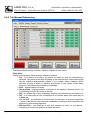
3.7.1. Tab Service Axes
Service-Axes tab contains in the upper part a table for display of the position of axes
and an additional button Clr.
Under the table there is a row of diagnostics diag and a three buttons: Licence,
Reload KNF and Reload NLC.
Table Axes
The table displaying the status of axes contains following columns:
• Axes – displays names of axes;
• Required – displays required position of axis in the mode of Irc display;
• Actual – displays the real position of axis in the mode of Irc display;
• Difference – displays the difference between the required position of axis and
a real position of axis. This difference is calculated by the system. However the
value of the position is loaded in another moment than the moment when the
required value is loaded, therefore the displayed value is considerably higher
than the real value depending on the speed.
• Ref – is status attribute of axis indicating whether the referencing was carried
out;
• InP – is status attribute of axis indicating status of In position the same way as
in Auto tab;
page 30
Operating of the Cnc886/Win general part, revision 7.12.2010
AREM PRO, s.r.o.
Automation, regulation, measurement
158 00 Praha 5, Nové Butovice, Nušlova 2275/15,
tel/fax +420 251 621 228
• In1 and In2 – are statuses of sensors used for indication of reference position which of sensors is used and how it depends on setting of servo-amplifiers.
• NSt and PSt – are statuses of end emergency sensors on axes. In the Yes
status everything is all right and the position is outside reach of these sensors.
• Err – is an error status attribute of servo-amplifier.
Clr
The button serves for zeroing of error status of servo drivers.
Diag
The row serves only for the purpose of service of the control program. The last window
displays total length of the track run in the given program. The track is evaluated in the
Test mode.
Licence
After pressing this button information on the term of control system licence validity
appears. It serves also for entering the code by means of which it is possible to adjust
the licence.
Reload KNF
Reload NLC
These two buttons are used only by service technicians. Non authorized use can cause
unpredictable problems.
page 31
Operating of the Cnc886/Win general part, revision 7.12.2010
AREM PRO, s.r.o.
Automation, regulation, measurement
158 00 Praha 5, Nové Butovice, Nušlova 2275/15,
tel/fax +420 251 621 228
3.7.2. Tab Service Servos
The tab displays information on position of servos. The axes mentioned till now were
virtual axes, which do not have to be realized by the same number and the same
geometry of servos = physical axes. A frequent case is for example driving of portal by
synchronous interaction of two servos. For better diagnostics it is allowed to monitor not
only behaving of virtual axes, but the status of servos as well.
In the column Axis there is a name of virtual axis, which belongs to the given servo.
Servo column is a list of names of servos.
Required displays required position of servo in its units.
Actual displays current position of servo in its units.
Correction displays correction calculated and applied by the control system, linearizing
the relation between virtual and physical axes. This correction is applied for
compensations of nonlinearity of rising of ball screws, racks etc. to achieve the highest
accuracy of the system as possible. At the calculation of corrections the system uses
values measured for example by interferometer method.
page 32
Operating of the Cnc886/Win general part, revision 7.12.2010
AREM PRO, s.r.o.
Automation, regulation, measurement
158 00 Praha 5, Nové Butovice, Nušlova 2275/15,
tel/fax +420 251 621 228
3.7.3. Tab Service Binars
The Service-Binars tab contains table of binary inputs and outputs of the system. They
are organized in 8 bit bytes. Meaning of individual bits and this way also notices in
individual fields are quite dependent on concrete version of the machine.
Fields for individual bits signalize status 0 by grey color, status 1 by green color.
Output bits of the system may be changed manually by touching (clicking) in the field.
Every touch means change of value. To prevent making changes by mistake it is first
necessary to activate the button OUTPUT CONTROL ENABLE. After leaving the tab
the button is automatically deactivated.
page 33
Operating of the Cnc886/Win general part, revision 7.12.2010
AREM PRO, s.r.o.
Automation, regulation, measurement
158 00 Praha 5, Nové Butovice, Nušlova 2275/15,
tel/fax +420 251 621 228
3.7.4. Tab Service Trends
This tab allows monitoring of servos parameters graphically. At each axis it is possible
to monitor current of the engine,
track deviation, and total load in
percentage. Further it is possible to
monitor the position, speed, and
acceleration. First three pieces of
information are calculated directly
from servo-amplifiers. Display of
current is basic. Change to another
o
f
offered quantities or adjustment of content may be
carried out by clicking on the button with the name
of servo under the graph. A dialogue, the example
of which follows, appears. A new method of
displaying the trend may be selected here. Another
servo may be also selected for the given color.
page 34
Operating of the Cnc886/Win general part, revision 7.12.2010
AREM PRO, s.r.o.
Automation, regulation, measurement
158 00 Praha 5, Nové Butovice, Nušlova 2275/15,
tel/fax +420 251 621 228
The Setting tab allows changing the scale on the horizontal axis of the graph and
density of grid. If something interesting is visible in the graph and you want prevent
disappearing it before you examine the picture, you may click in the graph and to fix the
picture. It stops moving. Another click returns you back to the real time.
Freezing and reactivation of the graph may be operated also by the checking character
in the setting dialogue.
3.8. Tab Errors
The tab Errors displays a record on error states and other events. The window in the
upper part of the tab allows view in the history of records from the last switch-on of the
system. The data are provided with date and time of origin of the record, type, and
specification of the record. Beside error states we can find there records on loading of
the file in the memory, initiation of program, completion of the program or its stopping
caused by an error or RESET button. At such event there is also a record on the row in
which the program was interrupted. This allows us to continue by means of the From
mode from the place in which the program was interrupted.
In case some error is active and the system is in the Error status, the error message
appears in the lower window.
The Error status shall be confirmed by Hmm button. However, if the error lasts, the
confirmation “aborts”. First it is necessary to remove the cause. But this relates to errors
page 35
Operating of the Cnc886/Win general part, revision 7.12.2010
AREM PRO, s.r.o.
Automation, regulation, measurement
158 00 Praha 5, Nové Butovice, Nušlova 2275/15,
tel/fax +420 251 621 228
such as “circuit breaker fallen out” etc. Program errors appear newly in the operation of
the program only.
Error messages and other messages displayed in this window are or are not depending
on the setting in the configuration file saved in the disc as well for service purposes. For
the purpose of operation there are two buttons available: Save Log.txt and
Load Log.txt. As the names suggest, they allow saving content of list of messages in
the disc and loading them again. The saving is carried out in a special file Log.txt, which
does not relate to earlier described file for service purposes. Saving and loading may
be useful in cases when the operator wants to record information, for example on the
program initiated last time, on the row in which the program was interrupted etc.
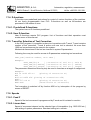
3.8.1. Other Information in Tab Errors
Also other useful information is saved in the record. For example in the mode Test the
minimum and the maximum values of selected axes are monitored and at the end
dimensions of the semi-finished product, to which the planned product fits, are written.
On the picture you can see a statement which informs you that dimensions of the
product shall be as follows: X=291.778 Y=291.778 Z=114.824.
Further the program was initiated in the Time mode and the result is the time 15
minutes 02 seconds, total track 67.515m with average speed 4491 mm/min.
page 36
Operating of the Cnc886/Win general part, revision 7.12.2010
AREM PRO, s.r.o.
Automation, regulation, measurement
158 00 Praha 5, Nové Butovice, Nušlova 2275/15,
tel/fax +420 251 621 228
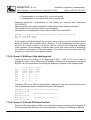
3.9. Editor
The picture is a sample of display while editing the CNC file. Working with editor is
intuitive and it perhaps does not need any comments. Considering the fact, that
Cnc886 is integrated in Windows environment, the operator may use for editing of
programs and other files other editors which is part of the operating system.
page 37
Operating of the Cnc886/Win general part, revision 7.12.2010
AREM PRO, s.r.o.
Automation, regulation, measurement
158 00 Praha 5, Nové Butovice, Nušlova 2275/15,
tel/fax +420 251 621 228
4. Manual Wheel AHW886
4.1. Basic Description
A manual wheel AHW886 is delivered with the Cnc886 system. It allows comfortable
operation at manual pre-travels of the machine tool and smooth change of feed in
automatic mode. Thanks to flexible cable with maximum length 6m it spans the entire
working area of the machine.
The manual wheel is designed as an intelligent periphery of the control computer.
Besides the circuit of the Central stop, which is solved separately by the separate pair
of conductors, all information is being transmitted by the serial line. The transmission is
controlled on the side of the wheel an inbuilt microcomputer, on the side of the control
system it is the Cnc886 program. For communication with the operator the wheel
contains:
• Two-row alphanumeric backlit display 2x16 characters
• Button with 100 locked positions for one rotation, equipped with incremental
sensor of position
• Six control buttons
The display serves for display of information sent by the control system to the wheel.
Beside the initial message,
page 38
Operating of the Cnc886/Win general part, revision 7.12.2010
AREM PRO, s.r.o.
Automation, regulation, measurement
158 00 Praha 5, Nové Butovice, Nušlova 2275/15,
tel/fax +420 251 621 228
HandWheel CNC886
AREM PRO ver-2.1
generated by the wheel, all others are sent by the control system and they reflect the
Cnc886 program status, however not the status of the wheel. So, if the wheel display
reports an error, it must not be an error of the wheel, but it may be an error detected by
the control system.
The button under the display serves in manual modes for control of position of the
selected axis, in the mode of the automatic program run for
feed control.
Control buttons have various functions in various situations. In
principle, it is possible to say that the upper three buttons
serve as selection buttons (selection of mode, function, axis
etc.); the lower buttons are operational (start/stop of shifting,
program etc.).
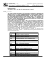
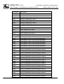
4.2. Display of Cnc886 Situation
Display wheels reflect the status of Cnc886 program. For statuses, which do not permit
control by wheel, there is a list of messages on the display summarized in the following
table:
Status
Off
Wheel Display
Switched off
Wheel - ver. 2.0
Initialization
Initialising
Wheel - ver. 2.0
Nor referred
Not referred
Wheel - ver. 2.0
Referring
Referencing
Wheel - ver. 2.0
Loading: xxxxxxx
Loading program
Wheel - ver. 2.0
Error
Error !!
Wheel - ver. 2.0
4.3. Display and Control while the Program is Running
If the technological program is started, the wheel display shows current status, value of
feed coefficient and text of the currently entered line (or its part).
page 39
Operating of the Cnc886/Win general part, revision 7.12.2010
AREM PRO, s.r.o.
Automation, regulation, measurement
158 00 Praha 5, Nové Butovice, Nušlova 2275/15,
tel/fax +420 251 621 228
Auto:
F= 50%
N1203 G1 X150 Y1
While the program is running the Cnc886 may be still in the status of suspension and
suspension with M0 function. In this situation the display shows:
Stop:
F= 50%
N1203 G1 X150 Y1
M0:
F= 50%
N1203 G1 X150 Y1
The display also shows the status of SPEED button of the control system. If it is
pressed, the letter F at the percentage of shift is replaced by small letter f.
Auto:
f= 50%
N1203 G1 X150 Y1
You can control the program operation by the wheel as follows:
You can change the feed coefficient by the button with the 1% step in the range from
0% up to 100%. Setting of the value to 0 completely stops moving of axes.
decreases coefficient by 10 %
increases coefficient by 10 %
changes status of the SPEED button of the control system
the same as the START+ button on the panel of Cnc886
program reset
stops the program the same way as the Stop button on the panel of Cnc886
4.4. Display and Control while the Program is Ready
If the Cnc886 program is in the Ready status, it is possible to use the wheel for initiation
of the program and to control individual axes manually. There is a dialog prepared for
selection of the required operation; the dialog is controlled by buttons of the wheel. The
basic level of the dialog is a status, in which the following option is shown on the
display:
Ready
Auto<
>Manually
Selects automatic mode
Selects manual mode of the wheel
page 40
Operating of the Cnc886/Win general part, revision 7.12.2010
AREM PRO, s.r.o.
Automation, regulation, measurement
158 00 Praha 5, Nové Butovice, Nušlova 2275/15,
tel/fax +420 251 621 228
4.4.1. Control of Automatic Mode
The display shows:
Ready:
F=100%
%1 {Program XYZ}
The first row shows the status and the value of the feed coefficient and status of the
SPEED button, the lower one shows the first row of the active program. In this status it
is possible to set the feed coefficient by means of the wheel and to initiate the program
by the wheel button, which has START+ function.
The RESET button of the wheel returns you back to the basic level of the dialog.
4.4.2. Manual Mode of Wheel – Axis Selection
In the manual mode of the wheel the display shows for example:
<- ax->
<-> X=
s=0.100
134.000
In the upper row the current step of the wheel is displayed. The title <- ax -> should
indicate that the axis for movement shall be selected by arrows. The lower row shows
the name of the selected axis and its current position.
In this status you may change position of the axis with the preset step by slow turning
the button. “Fast feeds” are available as well. Functions of buttons are as follows:
Selection of the previous axis
Access to the mode of step selection
Selection of the following axis
The same as the START+ button in the tab Manual Move. The speed of the
movement is according to the setting of the step 10x, 1x, 0.1x and 0.01x multiple of the
speed, set for the relevant axis in the configuration file.
Access to the basic menu
The same as the START- button in the tab Manual Move. The speed of
movement is according to the setting of the step 10x, 1x, 0.1x and 0.01x multiple of
speed, set for the relevant axis in the configuration file.
At the manual shifting of the axis invoked by the wheel or from the panel of Cnc886 the
display shows course and direction of move of shifting axis:
<- ax->
>>> X=
s=0.100
134.000
4.4.3. Step Selection mode
In the mode of step selection the display shows for example:
page 41
Operating of the Cnc886/Win general part, revision 7.12.2010
AREM PRO, s.r.o.
Automation, regulation, measurement
158 00 Praha 5, Nové Butovice, Nušlova 2275/15,
tel/fax +420 251 621 228
<- s ->
<-> X=
s=0.100
134.000
The upper row shows current step of the wheel. The title <- s -> should indicate that the
step should be selected by arrows. The lower row shows the name of the currently
selected axis and its current position.
In this status it is possible to change the axis position with preset step by slow turning of
the button. “Fast feeds” are available as well. Functions of buttons are as follows:
Selection of previous step
Access to another axes rose mode
Selection of the following step
The same as the START+ button in the tab Manual Move. The speed of the
movement is according to the setting of the step 10x, 1x, 0.1x and 0.01x multiple of the
speed, set for the relevant axis in the configuration file.
Access to the axis selection mode
The same as the START- button in the tab Manual Move. The speed of
movement is according to the setting of the step 10x, 1x, 0.1x and 0.01x multiple of
speed, set for the relevant axis in the configuration file.
4.4.4. Axes rose mode
A
X*
Z
Exit
B
Y
This level provides you with quick access to any axis. Selected axis is marked with *.
Now you can move it with the wheel. Step was selected in the „Step selection level“.
The axes names are placed on the display in the same pattern, like buttons on the
AHW886. That means, that the
axis etc.
button will select Z axis, the
selects the Y
RESET button moves you back to the „Step selection level“.
Pressing
and
simultaneously means „insert point“ in the case, that the
system is equipped wit TeachIn option.. The display will respond
<<< Point
>>>
<<< inserted >>>
page 42
Operating of the Cnc886/Win general part, revision 7.12.2010
AREM PRO, s.r.o.
Automation, regulation, measurement
158 00 Praha 5, Nové Butovice, Nušlova 2275/15,
tel/fax +420 251 621 228
Pressing
and
simultaneously invokes continuous movement in the „tool
direction“ away from the material.
Pressing
and
simultaneously invokes continuous movement in the „tool
direction“ towards the material.
4.4.5. Wheel in Mode from Line and from Position
By means of the manual wheel it is possible to control also dialogs in the From mode
and in the FromPos mode. After initiation of the program, which may be carried out
again by the manual wheel, and after finding the initial point, you will be asked about
initiation of M functions and about the pre-travel. In this moment wheel buttons function
as follows:
reduces the fast feed coefficient by 10 %
increases the fast feed coefficient by 10 %
changes state of the SPEED button of the control system
the same as START+ button on the Cnc886 panel and Yes answer
program reset
answer No
The most frequent procedure is as follows:
1.
Start the program in the selected mode
2.
Answer Yes to the question on function initiation
3.
Answer Yes to the question on the pre-travel
4.
Initiate continuation of the program
4.5. Safety at Work with Wheel
Following conditions for occupational safety were created on the side of the control
system:
• Manual movement invoked by the wheel may be stopped by pressing the
RESET button in the Cnc886.
• Manual movement invoked from the panel may be stopped by pressing the
RESET button on the wheel.
page 43
Operating of the Cnc886/Win general part, revision 7.12.2010
AREM PRO, s.r.o.
Automation, regulation, measurement
158 00 Praha 5, Nové Butovice, Nušlova 2275/15,
tel/fax +420 251 621 228
• After completion of the automatic program operation the wheel always ends in
the basic menu.
• After two minutes without operator’s activity on the wheel the system returns to
the basic menu.
• Interruption of communication by means of the wheel stops the manual
movement.
Machine control carried out by the wheel and the Cnc886 panel by more persons at the
same time is in praxis a life endangering machine operation.
Considering the fact, that the wheel cable allows the machine operator to initiate
movement from any place of the workplace, the operator must particularly observe
basic safety rules stated in machine operating conditions.
page 44
Operating of the Cnc886/Win general part, revision 7.12.2010
AREM PRO, s.r.o.
Automation, regulation, measurement
158 00 Praha 5, Nové Butovice, Nušlova 2275/15,
tel/fax +420 251 621 228
5. Basic Activities
The goal of this part of the user manual is to provide an easy orientation in the moment,
when you need to carry out a certain operation and to lead you to some of previous
chapters of the text.
5.1. Statuses of System
Recapitulation of system statuses:
Status
Power supply is switched off
Initialization after switching the power is in process
System is in powered, some axis is not referred
Referencing is in process
System is prepared and referred
Program is in process
Program suspended by M0 function
Program suspended by STOP button
Manual movement of axis is in process
Spindle initiated manually
Loading of program is in process
Error status
Message in the
window
Power OFF
Initialising
Not referred
Referencing
Ready
Running
Stopped by M0
Stopped
Manual move
Manually bin
Loading: xxxxxxx
Error
See also: 3.1 Status window
5.2. Switch-on of Power
After the initiation the program Cnc886 reports in the status window the Power OFF
status. In this status it waits for pressing the START button on the electrical cabinet.
After it is pressed the system changes into the Initialising status and then to the Not
referred status. In case something is wrong, it may also show Error status.
The Power OFF status is reported also after pressing the Central Stop button. Even in
this case it is necessary to press the START button to renew the supply to the power
part. But pay attention to the fact that the Central Stop is a button with detent.
Therefore it is necessary to release it beforehand.
5.3. Referencing of Axes
Referencing is initiated in the Manually Referencing tab – see 3.4.2 Manually
Referencing tab. Touch (or click by the mouse) the tab Manual, then the tab
Referencing. Touching the box in the column Sel select the axis for referencing.
Touching the START+ button on the screen you will initiate the process of referencing
the selected axis. You can interrupt the process by pressing the RESET button.
Referencing may be initiated only from the status Non referred and Ready.
page 45
Operating of the Cnc886/Win general part, revision 7.12.2010
AREM PRO, s.r.o.
Automation, regulation, measurement
158 00 Praha 5, Nové Butovice, Nušlova 2275/15,
tel/fax +420 251 621 228
5.4. Manual Control of Axes and Spindle
Manual movement of axes is initiated in the tab Manual Move – see 3.4.1 Tab
Manual Move. Touch (or click by the mouse) first the tab Manual, then the tab Move.
Touching the box in the column Sel you select the axis. Pressing the button START+
you will initiate movement of the axis in the positive direction. The movement is carried
out so long as you keep the button pressed. The axis stops with its release. The
Reverse direction of movement shall be initiated by pressing the START- button.
The speed of the movement may be selected in multiples of the value determined by
the constant for each axis. The multiples are 10x, 1x, 0.1x and 0.01x. They shall be
selected by means of buttons on the screen.
If the axis was referred, the system shall not allow you outside limits preset by machine
constants in the configuration file. If the axis is not referred, the check is not carried out
and the operator must pay particular attention. The pre-travel to the emergency end
sensor may bring useless complication. The manual movement may be initiated only in
statuses Not referred, Ready and Manual bin.
Moving of the spindle shall be initiated by buttons Fwd and Rwd (direction forward or
direction backwards). The system changes to the status Manual bin. The spindle starts
spinning and it continues even after releasing the press. It is possible to adjust the
revolutions/min by buttons Up and Dn. You can stop the spindle by pressing the
RESET.
It is possible to initiate the spindle also in the mode Stopped and Stopped by M0. You
can stop the spindle without switching out the running program by means of the STOP
button.
5.5. Manual Control of Functions
Other functions of the machine shall be initiated in the Manual Functions tab – see
3.4.3 Tab Manual Functions. Touch (or click by the mouse) first the tab Manual, then
the tab Functions. A tab with set of buttons appears on the display. Individual buttons
initiate individual functions. Their number and meaning is given by concrete version of
the machine.
5.6. Loading of Technological Programs and their Administration
Loading of technological programs and their administration shall be carried out in the
tab Library - see 3.5. Tab Library. Touch (or click by the mouse) the tab Library.
Loading and administration may be carried out in statuses Power OFF, Not Referred
and Ready.
Loading from serial line
shall be carried out by pressing the RS232 button. The system switches to the Loading
status. Now you can send the program from the computer, where you have created it.
After loading and display the system switches again to the original status. The only
exception is error status, which occurs if the program is loaded with the same number.
Loading may be interrupted by pressing the RESET button. If the loading was carried
out perfectly, the program is ready for initiation.
page 46
Operating of the Cnc886/Win general part, revision 7.12.2010
AREM PRO, s.r.o.
Automation, regulation, measurement
158 00 Praha 5, Nové Butovice, Nušlova 2275/15,
tel/fax +420 251 621 228
Loading from the disc
First select the program for loading in the window On disc. Then touch it by finger or
click by the mouse. Then press the button Load. After it is loaded and displayed the
system switches again to the original status. If a program with the same number is
already loaded, an error occurs. If loading was carried out perfectly, the program is
ready for initiation.
Selection of the program for initiation
If you want to start other program than the last loaded one, you can select it in the
window In memory and press Activate.
Program deletion
First select the program for deletion in the window On disc or In memory and then
press Delete/Remove button. More you can find in 3.5. Tab Library.
Saving the program in the disc
First select the program for saving in the window On disc or In memory and then press
Save as…. More you can find in 3.5. Tab Library.
Creation of new directory
Click first in the window On the disc and then press the New directory… tab. More
you can find in 3.5 Tab Library.
5.7. Setting of Corrections and Parameters
Setting of corrections and parameters and administration of files with corrections and
parameters shall be carried out in the tab Param. Touch (or click by the mouse) the tab
Param.
Setting and administration may be carried out in statuses Power OFF, Not referred
and Ready.
5.8. Confirmation of Error Message
If an error state occurs in the system, the running program is cancelled and a notice
Error occurs in the error window. Touch (or click by the mouse) the tab Errors. In the
lower part of the screen you can find window with red frame and notice with description
of the respective error. If it is an error, which requires your intervention (for example
circuit breaker fallen out, transformer error etc.) remove the cause. Then press the
button Hmm and confirm the error. If your intervention was not successful, error
appears again. If it was successful, the system confirms all errors and switches to the
idle status.
5.9. Resetting of Error of Servo-amplifiers
If the cause of the error status was an error in any of servo-amplifiers, you have to carry
out zeroing. For this purpose there is Clr button in the tab Service Axes – see 3.7.1.
Tab Service. Enter this tab. In the Err column there are transformers in error marked in
red. After you press the Clr button, the process of zeroing servos starts and it takes
page 47
Operating of the Cnc886/Win general part, revision 7.12.2010
AREM PRO, s.r.o.
Automation, regulation, measurement
158 00 Praha 5, Nové Butovice, Nušlova 2275/15,
tel/fax +420 251 621 228
approximately 5 seconds. Then the red marks in the Err column should change to grey.
Only then it is possible to confirm errors in the tab Errors.
5.10. Initiation of Technological Program
To be able to initiate the technological problem, it must be first loaded in the memory of
the serial line or from the disc and the so-called activation must be carried out – see
3.5. Tab Library and 5.6. Loading of technological programs and their administration.
If any of programs is activated, it is possible to start it by means of the START+ button.
However, the system must be in Ready status. The START+ button allows initiation of
the program from all tabs except Manual Move and Manually Referencing.
5.10.1. Test of Program - Test
It is possible to initiate the program also in the mode, in which no machine action is
carried out - only interpretation of the entire program and its testing in the syntactic
correctness and correctness of system of coordinates setting are carried out. All
required corrections and tests of limit positions of axes are active during the test. If the
test is carried out without errors, a program error can not arise at the normal mode and
at the same setting. At the same time, after the test you can find dimensions of the
product in the tab Errors see 3.8.1. Other information in tab Errors. You can set the
program test by selection the Test mode in the tab Auto – see 3.3. Tab Auto.
5.10.2. Measuring of Time of Program duration
If you set the mode Time in the tab Auto (see 3.3. Tab Auto) and initiate the program,
you can acquire very good estimation of the time necessary for realization of the
program. Statement of information after completion of the operation you can find in the
tab Errors – see 3.8.1. Other information in the tab Errors.
5.10.3. Initiation From Line or From Position
The program may be initiated also from the selected line of the program. The program
is running from the beginning of the mode Test, in which no action of the machine is
carried out. When the system finds the set line, it offers processing of M functions,
which are active according to the program and only then it offers the pre-travel in the
initial position. It is a position, which would be achieved by the system at the end of the
previous program line. After realization of the pre-travel the program is in the status
Stopped, i.e. the same way as after pressing the STOP button. It is possible to continue
after pressing the START+ button. The program then continues in a standard way.
Initiation from the line you can set by selection of the From mode and the field for the
number of the row in the tab Auto – see 3.3 Tab Auto.
It is often necessary to initiate the program from the selected line after it was interrupted
by an error, the working zone was disturbed by a careless operator, or the RESET
button was pressed for various reasons. Then you have to know the row in which the
program stopped. This information you can find in the records of events in the tab
Errors.
page 48
Operating of the Cnc886/Win general part, revision 7.12.2010
AREM PRO, s.r.o.
Automation, regulation, measurement
158 00 Praha 5, Nové Butovice, Nušlova 2275/15,
tel/fax +420 251 621 228
Similarly like from row, in some machines it is possible to carry out the initiation from
the current position of the machine. The program then finds the first position in the
program near the current position. See 3.3 Tab Auto
5.10.4. Single-step Operation Mode - Step
The Step mode allows realization of the program in the line by line mode. In this mode
the program stops after realization of each row and the STOP button on the fingerboard
lights up. The system is in the status Stopped. Another row is processed after pressing
START+.
The Step mode is switched on, if the Step button in the Auto tab is pressed in. This
button also switches on and off the step mode. – see 3.3. Tab Auto. It is possible to
enter the Step mode anytime; however it is suitable to enter it from the Ready mode or
from Stopped mode.
5.10.5. Suspension of Program
Suspension of the program is realized by pressing the STOP button on the fingerboard.
The system is in position Stopped. The program operation is renewed after pressing
the START+ button. The STOP button allows suspension of the program from all tabs.
Suspension causes stopping movement of axes. The spindle and M functions remain in
operation.
5.10.6. Modification of Feed
Speed of tool movement at the program operation is given by the requirement from the
program multiplied by the coefficient, which may be set in the tab Auto – see 3.3. Tab
Auto. The value may be set in the range from 0 up to 1.0. It is possible to change it
before initiation and during the program operation as well. The adjustment may be
carried out by buttons in the tab Auto – see 3.3. Tab Auto.
5.10.7. Modification of Spindle Speed
Revs of the spindle at the program operation are given by the requirement from the
program multiplied by the coefficient, which may be set in the tab Auto – see 3.3. Tab
Auto. The value may be set in the range from 0.5 up to 1.5. It may be changed before
initiation even during program operation. Adjustments may be carried out by buttons in
the tab Auto – see 3.3. Tab Auto.
5.11. Stop of Technological Program
Stopping of the technological program shall be carried out by pressing the button
RESET on the fingerboard. The RESET button allows stopping the program from all
tabs. All movements are stopped, the spindle is switched off, and all functions, as at the
termination of the program, are carried out. It is not possible to continue with the
program. It may only be initiated from the beginning.
page 49
Operating of the Cnc886/Win general part, revision 7.12.2010
AREM PRO, s.r.o.
Automation, regulation, measurement
158 00 Praha 5, Nové Butovice, Nušlova 2275/15,
tel/fax +420 251 621 228
5.12. Working in Service Mode
The tab Service Binars allows working in the service mode. Touch (or click by the
mouse) first the tab Service, then the tab Binars. The description of working with the
tab is stated in the Chapter 3.7.3. Tab Service Binary. Don’t forget that it is not possible
to check the meaningfulness and safety of your intervention at the manipulation in the
system tab!
5.13. Check and Setting of Licence
Check and setting of the licence relates only to users, who were limited in using of the
system for a certain period for business reasons. In the Service-Axes tab you can
display the dialog, which shows the validity time of the licence, by means of the
Licence button. It also offers access to another dialog, which allows entering code,
which shall adjust the licence.
5.14. System Switch-off
Switching out the system shall be carried in several steps. First it is necessary to
terminate actions of the Cnc886 program. It means to complete or to cancel realization
of the technological program, editing etc. Then it is possible to terminate the program
Cnc886 by clicking on the cross in the right upper corner of the window. Consequently it
is possible to terminate the work of the Windows operating system. At the end it is
possible to switch the distributor off by the main switch.
page 50
Operating of the Cnc886/Win general part, revision 7.12.2010
AREM PRO, s.r.o.
Automation, regulation, measurement
158 00 Praha 5, Nové Butovice, Nušlova 2275/15,
tel/fax +420 251 621 228
6. More Information about the System
6.1. System of coordinates and corrections
The goal of this chapter is to provide you with information on the processing of
positional information by the system. It shall be a guide for you in case of doubts on
correctness of setting of corrections.
Servo-amplifier units
• Servo-amplifiers work in units representing fragments of motor spindle
-20
rotations. Currently the unit represents 2 of the revolution, it is approximately
one micro. This unit must not be necessarily equal with the resolution of the
transducer. Transducer may work with grosser resolution. However information
is delivered in the above mentioned units.
• Based on data from the configuration file on transmissions the system recounts
units of the servo-amplifier in physical units, i.e. millimetres or degrees. The
information received this way is identified in the system as Irc.
Physical and virtual axes
In the system user’s view the axes identified as virtual are essential. Most frequently
they are axes X, Y, Z and further even rotary axes A, B, C. By means of them
coordinates of machining, machine position etc. are expressed. However, shifting in
each of these virtual axes may be realized by interaction of more servo-mechanisms =
physical axes. At some kinematics, operation of servo-mechanisms may project itself to
more virtual axes. However, because sometimes you need to know also status of these
physical axes for the purpose of service, physical axes are mentioned in the Cnc886 on
the level of service.
In further text all axes have already meaning of virtual axes.
Machine system of coordinates
Reference position of the transducer and hence the beginning of coordinates in units of
the transducer usually do not accord with the beginning of the machine system of
coordinate. Therefore the machine constant in the configuration file assigns position in
the machine system of coordinates to the position of the reference point.
The system of machine coordinates is determined by the manufacturer of the machine.
The G11 function works in these units as well. This function is used for example for pretravel to positions for tool change in the machining centre. Incorrect setting of position
of the reference point in the configuration file then may cause collision and damage of
the machine!
User’s system of coordinates
The machine user is allowed to shift the beginning of the system of coordinates against
the machine system of coordinates. It may be useful for example in case of using
special fixtures of the work-piece. The user’s system of coordinates is set in the tab
Manual Move.
The machine system of coordinates and the user’s system of coordinates coincide in
the basic setting; the zero shifting is preset.
The position in the users system of coordinates is called Absolute.
page 51
Operating of the Cnc886/Win general part, revision 7.12.2010
AREM PRO, s.r.o.
Automation, regulation, measurement
158 00 Praha 5, Nové Butovice, Nušlova 2275/15,
tel/fax +420 251 621 228
Tool corrections with shifting by functions G53 up to G59
According to the selection of the tool by the program and according to the active
function in the range from G53 to G59 the length of shifting of the tool point in the given
axis is deducted from the position Absolute. According to the selection of function G53
up to G59 the program shift is deducted from the beginning of coordinates.
The position received this way is called by the system Corrected.
Program shifting of functions G92
The last shifting, which influences the position, is the program shifting by function G92.
Its value is figured in the tab Auto. You can set this shifting by function G92 as follows:
the current position is “marked” as other position. The G92 function is usually used in
program cycles.
The value Corrected, from which shifting by G92 function shall be deducted, is called in
the system In program.
Conversion relations
The display of the position is based on the real position in units of the transducer and
the displayed value is calculated. During the program operation it is based on the
required value and the value is calculated in units of the transducer. For completeness,
there are figures for both cases:
InProg = Irc
+ RefPoint + UserOff - Tool - G5X - G92
Irc
= InProg - RefPoint - UserOff + Tool + G5X + G92
in which:
Irc
Units of the transducer recalculated to physical units
InProg
The value in the mode of display In program or the value
required by the program
RefPoint
Position of the reference point in the machine system of
coordinates
UserOff
Shifting defined by user’s system of coordinates
Tool
Tool correction in the given axis according to selection of
the tool T0 up to T999
G5X
Program shifting of the beginning defined in accordance
with the selected function G53 up to G59
G92
Shifting defined by function G92
Length correction
The system is able to work with length correction of the tool. It is applied particularly at
more complicated tools, for example five-axis cutters. The tool at the machining directs
in various moments to various directions and therefore it is not possible to manage with
ordinary correction in individual axes. When using the length correction the system
recounts the required position for machining to the position of the machine based on
knowledge of geometric settlement of the machine and the length of the tool. However,
this correction is not significant at all machines.
page 52
Operating of the Cnc886/Win general part, revision 7.12.2010
AREM PRO, s.r.o.
Automation, regulation, measurement
158 00 Praha 5, Nové Butovice, Nušlova 2275/15,
tel/fax +420 251 621 228
Radius correction
The system is able to work also with radius correction of the tool.
6.2. R-parameters
The system provides the user with 11000 parameters in total called R parameters and
identified as R0 up to R10999. These parameters serve for saving program variables, it
is possible to carry out simple calculations with them, test their value for null etc. They
also include parameters, which have preset function. Values of tool corrections and
shifting of the beginning by functions G53 up to G59 are saved in R parameters. On
one hand it uncovers various program options, but on the other hand it brings certain
danger in case they are handled carelessly.
At the initiation of the program the system is able to copy the whole set of parameters in
the memory and during the entire operation of the program it works with copies. That is
to say, if it would work always with the same set, the values of R parameters would be
changed by the program operation and new initiation of the program would carry out
other activity. When the Param tab is left and changes were made, the system saves
the entire set in the file on the disc. It proceeds the same way at the initiation of the
program in the Param tab. This file is loaded at the installation of the system, so values
of R parameters do not change after switching the system off and on.
Assigning R parameters with special functions is as follows. The goal is not an
explanation of the precise meaning of all parameters; it is only their enumeration and
position is mentioned there.
page 53
Parameter
Significance
R700
R701
R702
R703
Reserved for control of track filter
Reserved for control of track filter
Reserved for control of track filter
R710
R711
R712
R713
R714
R715
R716
R717
Selection of type of ramp ( 0 = linear, 1 = parabolic)
Maximum angle for G64
Interval for acceleration averaging
Maximum radial acceleration
Dead time for acceleration and deceleration
Minimum time for duration of the track section
Parameter for nonlinear speed correction
Parameter for nonlinear speed correction
R810
R811
R812
Maximum acceleration in G60 for parabolic ramps
Maximum acceleration standard for y
Time for achieving the maximum acceleration for
Minimum length of the section; otherwise ignore
Operating of the Cnc886/Win general part, revision 7.12.2010
AREM PRO, s.r.o.
Automation, regulation, measurement
158 00 Praha 5, Nové Butovice, Nušlova 2275/15,
tel/fax +420 251 621 228
page 54
Parameter
Significance
parabolic ramps
R900
R901
R902
R903
R904
Shifting of beginning in axis 0
Shifting of beginning in axis 1
Shifting of beginning in axis 2
Shifting of beginning in axis 3
Shifting of beginning in axis 4
R910
R911
R912
R913
R914
Total moved track in axis 0
Total moved track in axis 1
Total moved track in axis 2
Total moved track in axis 3
Total moved track in axis 4
R920
R921
R922
R923
R924
Moved track in axis 0 from the last lubrication
Moved track in axis 1 from the last lubrication
Moved track in axis 2 from the last lubrication
Moved track in axis 3 from the last lubrication
Moved track in axis 4 from the last lubrication
R930
R931
R932
R933
R934
Shift of coordinates of functions G53 in axis 0
Shift of coordinates of functions G53 in axis 1
Shift of coordinates of functions G53 in axis 2
Shift of coordinates of functions G53 in axis 3
Shift of coordinates of functions G53 in axis 4
R940
R941
R942
R943
R944
Shift of coordinates of functions G54 in axis 0
Shift of coordinates of functions G54 in axis 1
Shift of coordinates of functions G54 in axis 2
Shift of coordinates of functions G54 in axis 3
Shift of coordinates of functions G54 in axis 4
R950
R951
R952
R953
R954
Shift of coordinates of functions G55 in axis 0
Shift of coordinates of functions G55 in axis 1
Shift of coordinates of functions G55 in axis 2
Shift of coordinates of functions G55 in axis 3
Shift of coordinates of functions G55 in axis 4
R960
Shift of coordinates of functions G56 in axis 0
Operating of the Cnc886/Win general part, revision 7.12.2010
AREM PRO, s.r.o.
Automation, regulation, measurement
158 00 Praha 5, Nové Butovice, Nušlova 2275/15,
tel/fax +420 251 621 228
page 55
Parameter
Significance
R961
R962
R963
R964
Shift of coordinates of functions G56 in axis 1
Shift of coordinates of functions G56 in axis 2
Shift of coordinates of functions G56 in axis 3
Shift of coordinates of functions G56 in axis 4
R970
R971
R972
R973
R974
Shift of coordinates of functions G57 in axis 0
Shift of coordinates of functions G57 in axis 1
Shift of coordinates of functions G57 in axis 2
Shift of coordinates of functions G57 in axis 3
Shift of coordinates of functions G57 in axis 4
R980
R981
R982
R983
R984
Shift of coordinates of functions G58 in axis 0
Shift of coordinates of functions G58 in axis 1
Shift of coordinates of functions G58 in axis 2
Shift of coordinates of functions G58 in axis 3
Shift of coordinates of functions G58 in axis 4
R990
R991
R992
R993
R994
R1000
R1001
R1002
R1003
R1004
R1008
R1009
Shift of coordinates of functions G59 in axis 0
Shift of coordinates of functions G59 in axis 1
Shift of coordinates of functions G59 in axis 2
Shift of coordinates of functions G59 in axis 3
Shift of coordinates of functions G59 in axis 4
Tool correction Tool 00 in axis 0
Tool correction Tool 00 in axis 1
Tool correction Tool 00 in axis 2
Tool correction Tool 00 in axis 3
Tool correction Tool 00 in axis 4
Radial correction Tool 00
Length correction Tool 00
R1010
R1011
R1012
R1013
R1014
R1018
R1019
Tool correction Tool 01 in axis 0
Tool correction Tool 01 in axis 1
Tool correction Tool 01 in axis 2
Tool correction Tool 01 in axis 3
Tool correction Tool 01 in axis 4
Radial correction Tool 01
Length correction Tool 01
R1020
R1021
R1022
Tool correction Tool 02 in axis 0
Tool correction Tool 02 in axis 1
Tool correction Tool 02 in axis 2
Operating of the Cnc886/Win general part, revision 7.12.2010
AREM PRO, s.r.o.
Automation, regulation, measurement
158 00 Praha 5, Nové Butovice, Nušlova 2275/15,
tel/fax +420 251 621 228
Parameter
Significance
R1023
R1024
R1028
R1029
Tool correction Tool 02 in axis 3
Tool correction Tool 02 in axis 4
Radial correction Tool 02
Length correction Tool 02
etc. up to
R10990
R10991
R10992
R10993
R10994
R10998
R10999
...
Tool correction Tool 999 in axis 0
Tool correction Tool 999 in axis 1
Tool correction Tool 999 in axis 2
Tool correction Tool 999 in axis 3
Tool correction Tool 999 in axis 4
Radial correction Tool 999
Length correction Tool 999
The system is gradually preparing itself for situations with more then ten virtual axes.
Placing of tool corrections in R parameters soon faces historically selected scheme of
their placing. Therefore, please, do not rely on placing of parameters according
indexes. Other methods of approach are available, for example:
TOOL_COR[001,X
]
TOOL_COR[001,Radius]
TOOL_COR[001,Length]
6.3. Programs in Memory
The program for realization has to be first loaded from the disc or serial line to the
computer memory. The reason is speed of program processing. The memory for
programs is limited by space reserved for this purpose. It may differ according to
concrete setting; however it is not smaller than 2MB. More programs may be loaded in
the memory in the given moment. Its reason is particularly the option to access one
program by means of another as a subprogram. In this case, do not forget to load really
all necessary programs in the memory and to set the one, which plays the role of the
main program, as the active one.
page 56
Operating of the Cnc886/Win general part, revision 7.12.2010
AREM PRO, s.r.o.
Automation, regulation, measurement
158 00 Praha 5, Nové Butovice, Nušlova 2275/15,
tel/fax +420 251 621 228
7. Programming Language Description
CNC program is an order of commands for the control system. The program contains
necessary information for moving and other machine activities. Commands of the
language allow also branching in the program, cycles and accessing subprograms.
7.1. Program Structure
The program is organized in lines. The first line is reserved for the number of the
program.
The program ends on a line, in which the function for the program end is stated – M30.
It needs not to be necessarily the last line.
Lines (with exception of the first one) are numbered. The line number is stated on its
beginning after the character N.
Usual structure of the program is displayed in the following diagram:
Example:
%15
{beginning of the program}
N1
……
N16
……
N156
……
N945 M30
{end program}
7.1.1. First Line – Number and Name of Program
The character % is the feature for the beginning of the program. Then the number of
the program, which consists of characters of 1 up to 8, follows. The program number
must be in the range from 1 up to 99999999.
Selection of the number of the main program and subprograms depends on the user
and the system shall not rewrite it. We recommend a suitable division of the range
value between main programs and subprograms for better understanding.
The number of the program may be extended by the name of the program
{commentary}.
The number and the head are decoded during activation of the program or the
subprogram.
Example:
%12 {product 124}
7.1.2. Command Prompts
Each command line of the CNC program starts with the number of the row preceded by
letter N. Number of the row must be in the range from 1 up to 99999999. Further it
contains succession of commands. Most of commands consist of the written
abbreviation and natural number or real value. Marking of individual functions is
deduced from the standard ISO code. Commands consist of one letter and numerical
value. The number may be also the number of the line or number of the subprogram.
In the process the basic set of functions was extended by further options. However,
naming by letter and number was already abandoned and functions are created in form
of key words, such as IF, THEN, GOTO etc.
page 57
Operating of the Cnc886/Win general part, revision 7.12.2010
AREM PRO, s.r.o.
Automation, regulation, measurement
158 00 Praha 5, Nové Butovice, Nušlova 2275/15,
tel/fax +420 251 621 228
Real numerical values are parameters of functions and they determine e.g. speed, revs,
value of coordinate etc. Values may be stated in form of mathematical expression. The
term may contain numerical constants or indirect references to the so called R
parameters and MP parameters. Parameters are in point of fact registers, or if you want
variables, of your program. Some have special purpose; others are full-available for the
program. (More about expressions you can find in a separate chapter.)
At the branching of the program it is possible to use logic expressions. They may
contain values of binary inputs and outputs of the system, numerical comparisons, and
all usual logic operations.
Part of the command line may contain also the command for assignment allowing
performance of simple calculations with constants and values of parameters.
Special command may be also a commentary. It is a succession of figures closed by
symbols { and }.
Individual commands and their syntax we will go through later. There is only their brief
summary.
page 58
Word for row number
N
Preparatory function
G
Determination of axis name
A, B, C, L, O, P, U, V, W, X, Y, Z, chain
Radius of circular interpolation
RC
Word for feed
F
Word for spindle speed
S
Selection of tool correction
T
Word for time delay
TI
Word for M function
M,H,D
Word for program GOTO
BN, B%
Word for conditioned command
IF THEN
Commentary for CNC program
{……….}
Identification of R parameter
R
Identification of MP parameter
MP
Identification of binary I/O variable
BIN
Modifier of M function
$
Operators of numerical expressions
+,-,*,/
Operators of logic expressions
! , || , &&
Command for Go To
GOTO
Commands for calling subprograms
CALL, CALL%
Display of text constant
ECHO, WARNING
Induction of error state
ERROR
Prefix of mode of M functions realization
NOWAIT
Operating of the Cnc886/Win general part, revision 7.12.2010
AREM PRO, s.r.o.
Automation, regulation, measurement
158 00 Praha 5, Nové Butovice, Nušlova 2275/15,
tel/fax +420 251 621 228
Command for manipulation with R
parameters
LOAD_RPARS
Prefix for manipulation with R parameters
SAVED
Special setting
MIRROR, SCALE
Example:
N10 G1 X100
Y5.4
F1000
S500
M3
{commentary}
N10
{row number}
G1
{ G-words are preparative functions}
X100
{naming of axes and target coordinates}
F1000
{feed speed in mm/min.}
S500
{speed of spindle 1/min for main spindle}
M3
{M-functions are logic functions – some with predefined functions and some
with free functions – their processing is programmed in PLC}
{......}
{commentary is stated in brackets "{...}". In the commentary it is possible to
use only viewable 7-bit ASCII characters. It is not allowed to use brackets {}
in the commentary.}
End of the program
Word M30 {end of program} ends the CNC program. The control system switches to the
control mode RESET.
Function M17 ends the CNC subprogram and returns back to the superior program.
7.2. R parameters and MP parameters
The system provides the user with 11000 parameters in total. They are called R
parameters and identified R0 up to R10999.
These parameters serve for saving variable programs, it is possible to realize simple
calculations with them, test their value for null etc. Most of them are parameters, which
have a function assigned in advance. For example values of tool corrections and
shifting of the beginning by functions G53 up to G59 are saved in R parameters. On
one hand it uncovers various program options; on the other hand it brings certain
danger, if they are not used carefully.
At the initiation of the program the system copies the entire set of parameters (basic
set) in the memory and works with copies during the entire operation of the program. If
it would work always with the same set, values of R parameters would be changed by
the program operation, and new initiation of the program would carry out other activity.
But due to the fact that this option may be sometimes desirable, special functions and
prefixes are prepared; they allow working with both sets of parameters. They are prefix
SAVED and function LOAD_RPARS; (see further).
The basic set of R parameters is at the completion of the program (by RESET, by error,
or in a standard way M30) saved on the disc. These R parameters values, which were
modified by the program by means of SAVED prefix, are therefore modified - copy and
page 59
Operating of the Cnc886/Win general part, revision 7.12.2010
AREM PRO, s.r.o.
Automation, regulation, measurement
158 00 Praha 5, Nové Butovice, Nušlova 2275/15,
tel/fax +420 251 621 228
the basic value as well, are saved in the changed form. This way it is possible to count
pieces etc.
Command LOAD_RPARS(number1,number2) causes rewriting of parameters with
indexes from number 1 to number 2 from the basic set to set of copies.
R parameters are saved in 64-bit real format. The R-parameter is determined by letter
R and index (formula). However, this index (formula) may be dependent on other R
parameter. This way the R parameter is determined directly or indirectly. Let us explain
determination of R parameters in examples.
R8
RR8
RRR8
R(R1+3)
Direct determination of parameter. The eighth parameter is used.
Indirect determination. The content of R8 parameter is read. The value is
adjusted to an integer by cutting off the decimal part and the result is used
as the index of parameter.
Indirect determination of the second order. The content of R8 parameter is
read. The value should be adjusted to the integer by cutting off the
decimal part and the result should be used as parameter index. Its content
is read. The value is adjusted to the integer by cutting off the decimal part
and the result is used as parameter index.
Index of R parameter is given by sum of content of R1 parameter and
number 3.
Indirectness of determination may be randomly deepened. However, the indirect
addressing of higher order does not have large importance in praxis.
MP parameters are determined above all by keeping variables serving as input
parameters of M functions, provided some are used. Therefore it is not recommended
to use them as variables of the program. File of MP parameters contains currently 2000
items. Unlike R parameters the work is carried out only with one set.
7.2.1. Value
The word value in the subsequent text shall be understood as a number determined by
the expression. The expression is written in a usual manner. It may contain numbers,
references to R parameters and MP parameters, operations + , - , * , / and selected
mathematical functions. It is possible to use brackets, practically in unlimited depth, in
formulas.
7.2.2. Arithmetic Operations and Assignment Command
Part of the command line may be created by one or more commands for assigning.
They are carried out in the order, in which they are stated in the row.
The form of the command is as follows:
<R parameter> = <expression>
or
SAVED <R parameter> = < expression >
Place of character = it is possible to use as well:=
page 60
Operating of the Cnc886/Win general part, revision 7.12.2010
AREM PRO, s.r.o.
Automation, regulation, measurement
158 00 Praha 5, Nové Butovice, Nušlova 2275/15,
tel/fax +420 251 621 228
The command calculates the expression on the right side and saves the result in R
parameter. The expression may be a value, calling of standard function, addition +,
subtraction - , multiplication * or division / of values.
Calling of standard function includes:
SIN(expression)
sinus of the value of expression stated in brackets. The value is in
degrees.
COS(expression) cosine of the value of expression stated in brackets. The value is in
degrees.
TAN(expression)
tangent of the value of expression stated in brackets. The value is
in degrees.
CTG(expression)
cotangent of the value of expression stated in brackets. The value
is in degrees.
SQRT(expression) root of the value of expression stated in brackets.
As indicated in the description, the argument of the function may be again an
expression!
Examples of
R0:=5
R0:=R1+3
R0:=R1-R2
R0 =R1*R2
R0 =R1/R2
arithmetic operation:
addition
subtraction
multiplication
division
Following examples show some options for using R parameters and commands.
Example 1:
Example 2:
Example 3:
N10 R8=6.25 {R8 acquires value 6.25}
N10 R8=R6 {R8 acquires value of the parameter R6}
N1 R6=4
N2 R4=10
N10 R8=RR6 {R8 acquires value 10 – indirect
determination}
Example 4:
Example 5:
N20
N20
N30
N10
Example 6:
R1=2.5*(R2+R3) R1= R1/R5
R16=2.5*R6 R8=R145+R16
XR8 YR16
G1 XR2 YRR3 FR3
As already said, the prefix SAVED causes that the value of the expression is saved in
the set of copies and in the basic set as well. The prefix relates only to one command
for assignment.
Example 7: N10 SAVED R1=R1+1
page 61
Operating of the Cnc886/Win general part, revision 7.12.2010
AREM PRO, s.r.o.
Automation, regulation, measurement
158 00 Praha 5, Nové Butovice, Nušlova 2275/15,
tel/fax +420 251 621 228
Examples of use of standard functions:
R0:=45
R2:=R1*SIN(R0)
R3:=R1*COS(R0)
R2 =R1*SIN( 180 + R0 )
R5 =SQRT( R6*R6 + R7*R7 )
7.3. Control of Program flow
Commands GOTO, CALL, CALL%, BN, B% and the structure IF THEN are determined
for program operation control.
7.4. Unconditional Branch
7.5. GOTO statement
Example: (go to line number 10)
N157 G1 X50 Y20 F1000
N158 GOTO 10
N159 G0 X50
N158
Order number of the row
GOTO
Word for go to
10
Number of the row, to which the GOTO should be carried out
It is possible to achieve the same effect even with older version by means of command
BN10.
The row number may be stated also by a expression. The real value of the expression
is converted to integer and it is used as the row number. If there is no line with the
given number, an error occurs.
If the GOTO command is stated in the line, no other commands may be stated in the
same line.
7.5.1. Calling of Subprogram CALL and CALL%
Two variants are available. The command CALL carries out calling within the scope of
the relevant program. The parameter of the command is the line number. Variant
CALL% - as the subprogram - calls other program and the parameter is number of the
program (identified by symbol % on the first line).
In both cases the return from subprogram calls function M17 or M30.
Example: (calling of subprogram on row 1000)
N157 G1 X50 Y20 F1000
N158 CALL 1000
N159 G0 X50
N158
Order number of row
CALL,CALL% Word for calling
10
Number of row or program to which the calling should be
carried out.
page 62
Operating of the Cnc886/Win general part, revision 7.12.2010
AREM PRO, s.r.o.
Automation, regulation, measurement
158 00 Praha 5, Nové Butovice, Nušlova 2275/15,
tel/fax +420 251 621 228
If the command CALL or CALL % is on the row, no other command may be in the row.
7.6. Conditional Branch
7.6.1. Conditional Go to in Program BN<line> R-Parameter
In previous versions of the program it was only one variant of branching. It was
determined particularly for realization of cycles.
Conditional go to is carried out when the stated R parameter is different from zero (R12
in following cases). After every test number 1 is automatically subtracted from
parameter.
Conditional branching is used generally for realization of program cycles. However, the
initial setting of R parameter must not be part of the cycle; otherwise an endless loop is
created.
Example: (go to row number 25)
N10 R12:=8
N25 G0 Z8
N150 G1 Z0 F500
N157 G1 X50 Y20 F1000
N158 BN25 R12
N159 G0 X50
N158
BN
25
R12
Order number of row
Word for go to
Number of row to which the go is carried out
Number of cycles
7.6.2. Structure IF THEN
Structure IF THEN represents conditional command. If it is used in the line, no other
commands may be stated in the line in front of the word IF.
The form of the command is as follows:
IF <logic expression> THEN <commands>
Logic expression is created in a usual manner from operands, which are logic variable
or numerical relation and by means of logic operators. It is possible to use brackets in
expressions.
Logic operators:
!
logic negation; relates to operands placed behind the operator
&& logic product between two operands
||
logic sum of two operands
Operands may be as follows:
BIN<number> Indicates logic value of binary variable. For this purpose the binary
inputs and outputs of the system are numbered from zero to variable limit. List
of binary variables is in the tab Service Binary of the control system and they
are numbered in a manner that the variable in the upper right corner conforms
to number 0 (bit D0). The numbering continues to the left up to the order
number 7, then to the right on the second row etc.
page 63
Operating of the Cnc886/Win general part, revision 7.12.2010
AREM PRO, s.r.o.
Automation, regulation, measurement
158 00 Praha 5, Nové Butovice, Nušlova 2275/15,
tel/fax +420 251 621 228
Numerical relation
Numerical relation is comparison of values of two numerical expressions.
Following operators are available:
==
For equality
!=
For inequality
<
Less
>
Greater
<=
Smaller or equal
>=
Greater or equal
Assessment of logic expressions needs one commentary. Interpreter of CNC program
is processing lines in advance before their real performance. Within the scope of this
conversion also other questions related to “look ahead” functions, such as planning of
speed, track modification by radial correction etc., are solved. At the assessment of
logic expressions, in which there is at least one value of binary variable, the interpreter
must stop the conversion and wait for processing of all previous commands, because
they may change the value of the binary variable. Therefore the movement always
stops in this place of the program.
<Commands> behind the key word THEN represent list of commands, the same way
as they may be stated in the command line with exception of another structure IF
THEN.
Examples:
N10 IF (R12==8) THEN GOTO 1200
N25 IF BIN36 THEN CALL 128
N50 IF (R1>10) && (R1<20) THEN M3 S12000 F7000
7.7. ECHO Function
Function serves for writing of texts in a special row in the tab Auto of the control
system. It allows displaying of phase of the program, instruction to the operator at the
suspension of functions M0 etc.
Chain of figures in quotation marks shall be stated behind the key word ECHO.
Example:
N10 ECHO ”Roughing”
7.8. WARNING Function
Function WARNING displays text, which follows. It is displayed in a special window
overlapping cnc886. The text is at the same time written in a record in the Error tab.
Example:
N10 WARNING ”You certainly must be tired and need a rest!!”
7.9. ERROR Function
ERROR function calls program error and displays a text, which follows. The text is
written at the same time in the record in the Error tab.
page 64
Operating of the Cnc886/Win general part, revision 7.12.2010
AREM PRO, s.r.o.
Automation, regulation, measurement
158 00 Praha 5, Nové Butovice, Nušlova 2275/15,
tel/fax +420 251 621 228
Example:
N10 ERROR ”Position of tool changer is occupied!”
7.10. Special Function of System of Coordinates Transformation
A pair of functions for mirroring and change of scale is experimentally established in the
new version. For the time being they are designed in a very simple way, which does not
reflect concrete geometry of the machine. It may be used well at two-axes or three-axes
systems; the situation is more complicated at multi-axes systems. Therefore we
recommend paying particular attention at the application of these functions.
7.11. Mirroring
The command has a following form:
MIRROR = < expression>
Value of the expression in the command MIRROR shows order number of the axis, the
required coordinates of which have to be multiplied by -1.
For this purpose axes are numbered from zero. It means that in case of a system with
three axes in row X, Y, Z, then 0 indicates X, 1 indicates Y and 2 indicates Z. If the
value of the formula is -1, mirroring is not applied.
Mirroring is applied in all other processed rows of the program, until the value of the
MIRROR changes.
At the calculation of coordinates the control system first determines the required
position given by CNC program. Only then possible tool corrections and shifts given by
G5X functions and change of the beginning of the system of coordinates in the manual
setting shall be carried out.
Mirroring can not be applied in programs, in which circle interpolations and radial
corrections appear.
The control system does not solve possible senseless values of the formula.
After completion of the program MIRROR = -1 is automatically set, it means without
mirroring.
7.11.1. Change of Scale
The command has a following form:
SCALE = < expression >
Value of the expression in command SCALE determines a number, by which all
required coordinates of CNC plan and also diameter of RC circle shall be multiplied.
Multiplication of coordinates precedes the mirroring application. Theoretically it is
possible to use also negative values of expression; however they shall not function well,
if a circle interpolation or radial corrections appear. After completion of the program the
SCALE = 1 is set automatically, it means without change of the scale.
7.12. M-function
M–functions are predefined instructions for control of various functions of machine. Mfunctions in CNC row proceed always when axes are in idle status. (It does not relate to
M17 function).
page 65
Operating of the Cnc886/Win general part, revision 7.12.2010
AREM PRO, s.r.o.
Automation, regulation, measurement
158 00 Praha 5, Nové Butovice, Nušlova 2275/15,
tel/fax +420 251 621 228
This character may be suppressed by prefix NOWAIT at the beginning of the line. M
functions or D and H functions with this prefix are processed simultaneously with
moving on the stated row.
Transition to the following line comes only after completion of functions and
movements. Prefix NOWAIT is valid only for the given line.
7.12.1. Pre-defined M-functions
M0
M3
M4
M5
CNC program stops after processing of CNC line. The program may continue
after pressing START+ button.
Activation of spindle rotation clockwise. It starts CNC axes, which are declared
as the main spindle at the beginning of processing CNC row.
Activation of spindle rotation counterclockwise. It starts CNC axes, which are
declared as the main spindle at the beginning of processing of CNC row.
Stopping of spindle. It stops CNC axes, which are declared as the main
spindle at the end of processing of CNC row. At positioned axes the spindle
automatically stops in zero position.
Example: {Operation of spindle}
N10 M3 S500 {start of spindle}
N20 X... Y...
N30 M5
{stop of spindle}
N50 C45 F300
{positioning of spindle as C-axis}
M17
M30
End of subprogram. This function induces return in the subprogram back to
the calling CNC program.
End of program. This function induces interruption of CNC program operation.
The system automatically switches to RESET status.
User M–functions
User M–functions require PLC program. List of functions and their operation must
create an annex of this document. M-functions may be modified by prefix $<number>.
Meaning of prefix is given by implementation of M-function and it depends on a
concrete machine.
7.13. H-functions
H–functions are predefined instructions for control of various functions of the machine.
All are freely programmable from PLC. H-functions as well as M-functions are
processed in idle status of axes.
7.13.1. Pre-defined H-functions
The system has no predefined H-functions.
7.13.2. User H-functions
User H-functions require PLC program. List of functions and their operation must be
included in the annex of this manual.
page 66
Operating of the Cnc886/Win general part, revision 7.12.2010
AREM PRO, s.r.o.
Automation, regulation, measurement
158 00 Praha 5, Nové Butovice, Nušlova 2275/15,
tel/fax +420 251 621 228
7.14. D-functions
D–functions are predefined instructions for control of various functions of the machine.
All are freely programmable from PLC. D-functions as well as M-functions are
processed in idle status of axes.
7.14.1. Pre-defined D-functions
The system has no D-functions predefined.
7.14.2. User D-function
User D–functions require PLC program. List of functions and their operation must
create annex of this manual.
7.15. T-word for Selection of Tool Correction
In the CNC program it is possible to place tool corrections with T-word. T-word contains
number of tool correction. T-word is active until new tool is selected. No more than
1000 tool corrections may be saved in the system.
Mechanical dimensions of the tool are inserted in system R-parameters.
Following form may be used for access to R-parameters containing tool corrections:
TOOL_COR[ machine number, axis name ]
Example:
TOOL_COR[001,X
] {correction of tool no.1, axis X}
TOOL_COR[001,Radius] {correction of tool no.1, radius}
TOOL_COR[001,Length] {correction of tool no.1, length}
The parameter determined this way may be used in formulas as a target of assignment.
Example:
N10 G1 X100 Y50 T1
{placing of correction T1}
N20 ..
N130 G1 X450 T56 {placing of corrections T56}
N240 ..
N450 G1 Y18 T1
{placing of correction T1}
N490 M30
{cancellation of correction}
Tool correction is switched off by function M30 or by interruption of the program by
means of RESET.
7.16. Speeds
7.16.1. Feed F
Speed of the tool movement is programmed by F-word and it is stated in mm/min.
7.16.2. Linear Axes
Speed of movement depend on the selected type of interpolation {e.g. G0/G1/G2 etc.}
and setting of system parameters. Standard setting is in mm/min.
page 67
Operating of the Cnc886/Win general part, revision 7.12.2010
AREM PRO, s.r.o.
Automation, regulation, measurement
158 00 Praha 5, Nové Butovice, Nušlova 2275/15,
tel/fax +420 251 621 228
G1/G2/G3
All axes programmed in CNC line are interpolated in a manner by means of which the
resulted speed of the tool corresponds to the programmed feed F in mm/min.
Example:
N10 G1 X100 Y50 Z20 F5000
G0
The track of the tool is calculated in a manner by means of which the resulted track is
linear. Speed F is in this case used from machine constant. The maximum speed of
movement of the tool track is determined by the slower axis.
Example:
N10 G0 X100
Y50
7.16.3. Rotating Axes
Independent rotary axis moves by speed F in degrees/min.
Example:
N10 G1 X100 Y100 C180 F500 {C – rotary axis}
7.17. Speed of Rotation S
Speed of the spindle is programmed in revs per minute. The speed of rotation is limited
to the maximum speed set in the machine constant.
Example:
N10 G1 X100
Y50
F10 S1500 M3
7.18. G-function
Depending upon DIN66025 part 2 the standard preparative functions are CNC
functions, which describe interpolation connection of CNC axes.
Standard preparatory functions are in functional groups, by means of which only one
function from each group may be activated at a time.
Some functions are active already before start of the program (the so called preparatory
functions). Some functions are retaining, other must repeat on each CNC line.
•
•
•
•
•
•
•
•
•
page 68
Group 1
Group 2
Group 3
Group 4
Group 5
Group 6
Group 7
Group 8
Group 9
Interpolation
Waiting
Selection of plain
Compensation
Shifting of beginning
G92 and G93 - new position
Speed characteristics G60 G64
Absolute position G11
Measuring of distance – absolute/incremental
Operating of the Cnc886/Win general part, revision 7.12.2010
AREM PRO, s.r.o.
Automation, regulation, measurement
158 00 Praha 5, Nové Butovice, Nušlova 2275/15,
tel/fax +420 251 621 228
7.18.1. Group 1: Interpolation
All commands for interpolation consist of a word indicating type of interpolation and list
of interpolated coordinates with entered end point. The end point may be entered
absolutely or incrementally according to the active function G90/G91. The end point
further influences G11 function, which sets absolute system of coordinates of the
machine. The manner of connection of individual track sections influences functions
G60/G64. In case the G64 is active the system carries out connection of individual lines
of the CNC program without loss of speed, eventually it adjusts the speed in
accordance with the dynamics of the entire system. In case of G60 the shifting stops at
the end of each section.
7.18.1.1. G0 Shift by Fast Feed
All axes reach to the programmed position at once. Acceleration ramps for fast feed are
applied at the movement.
Programmed F speed is not effective. As soon as the G0 selection is cancelled, the F
speed is activated again.
The fast feed speed is given by machine configuration and in case of need it is reduced
so that no axis could exceed its speed limit.
Example:
N10 G0 X100 Y50
7.18.1.2. Linear Interpolation G1
The fast feed speed of the tool track is programmed under the F address for linear
interpolation. Linear interpolation is permitted in all axes at once. The maximum speed
of tool track feed is determined by the slowest axis. G1 is active by default in
preparatory functions.
Example:
N10 G1 X100 Y500 Z250 C100 A20 F1000
7.18.1.3. Circular Interpolations G2 and G3
Speed of feed is programmed by F function. Circle interpolation may be carried out in
one plain. Circle plain is determined by functions for selection of plain {G17/G18/G19}.
G2
Circle interpolation – clockwise
G3
Circle interpolation – counterclockwise
Axes, which are programmed additionally to circle axes, are included in the interpolation
context so that they reach the end coordinate in the same time as the circle axes.
End position, coordinate of centre or curve radius must be with accuracy 0.001 mm,
otherwise an error message is displayed.
page 69
Operating of the Cnc886/Win general part, revision 7.12.2010
AREM PRO, s.r.o.
Automation, regulation, measurement
158 00 Praha 5, Nové Butovice, Nušlova 2275/15,
tel/fax +420 251 621 228
Circle interpolation by radial programming RC
Circle radius may be programmed in the row G2/G3 with RC … . The entire circle may
be programmed with two half circles. Negative value of the radius indicates curve with
angle larger than 180 degrees.
Example:
N10 G1 X100 Y0 F1000
N20 G2 X110 Y0 RC10
RC10.}
{Radius of the curve is programmed by
Circle interpolation with determination of centre
Circle interpolation may determined also by the end point and the centre of the circle.
Following words serve for determination of the circle centre:
I
coordinates of centre in axis X (first axis of the system)
J
coordinates of centre in axis Y (second axis of the system)
K
coordinates of centre in axis Z (third axis of the system)
Coordinates of the centre are always relative with regard to the initial point of
interpolation.
7.18.2. Group 2: Waiting
7.18.2.1. Delay Period (TI)
Time delays are programmed in the CNC program in seconds.
Example:
N10 TI2.5
N10 TIR2
{time delay in constant}
{time delay in R parameter}
Time delay is generated before initiation of shifting stated in the same row.
Time of delay is effective only for one row.
7.18.3. Group 3: Selection of Level G17 and G18 and G19
Interpolation plain must be set for circle interpolation and for radius correction. G17 is
placed implicitly. All functions of plain selection are self-keeping.
The plain is selected by means of coordinates X, Y, Z.
• G17 = selection of plain X-Y (first and second axis of the system)
• G18 = selection of plain X-Z (first and third axis of the system)
• G19 = selection of plain Y-Z (second and third axis of the system)
7.18.4. Group 4: Compensation
Following instructions are used for compensation of the track depending on the tool
radius correction. Compensation of the tool track is carried out for radius of the tool
point or cutter radius. All functions are self-keeping.
• Cancellation of selection of tool radius compensation G40
page 70
Operating of the Cnc886/Win general part, revision 7.12.2010
AREM PRO, s.r.o.
Automation, regulation, measurement
158 00 Praha 5, Nové Butovice, Nušlova 2275/15,
tel/fax +420 251 621 228
• Compensation of tool radius G41, tool for left profile
• Compensation of tool radius G42, tool for right profile
Machined plains for compensation of tool radius are selected with instructions
G17/G18/G19.
Machined plain must not be changed if compensation of tool radius is selected.
The number of the current tool must not be changed.
Cancellation of compensation of tool radius is after G40 or after M30.
Example 1: Placing and cancellation of radial correction
N10 G1 G41 X100 F500
N20 G1 G40 X150 F500
At the passing of internal edges the tool goes closer to the end of the section so that it
does not interrupt the following section. However, if on the subsequent section there is
no point, by means of which it would be able to continue with machining, message
notice appears. At the passing of outside edges linear and circle section is entered by
the system in dependence of the track shape. This section is not recorded in the CNC
program, but only saved in temporary memory.
7.18.5. Group 5: Shifting of the starting point
Calling functions for shifting of the beginning is G53 – G59. G 53 is up to date in
possible functions. All functions are self-keeping. Shifting of the beginning is cancelled
by M30. List of R-parameters for shifting the beginning is stated in the following table:
G53
G54
G55
G56
G57
G58
G59
axis0
R930
R940
R950
R...
R...
R...
R...
axis1
R931
R941
R951
R...
R...
R...
R...
axis2
R932
R942
R...
R...
R...
R...
R...
Functions G53 up to G59 are self-keeping. Stating the new one cancels the previous
one. R-parameters may be read/written by the CNC program.
Example of
N10 G54 G0
N20 B%4711
N30 G55 G0
N40 B%4711
N50 G53 G0
use of shifting of beginning:
X0
{processing of part 1}
X0
{processing of part 2}
X0
7.18.6. Group 6: G92 and G93 New Position
Function G92 sets program shifting of coordinates during processing of the program so
that the real position becomes the required position. In doing so no shifting is realized.
page 71
Operating of the Cnc886/Win general part, revision 7.12.2010
AREM PRO, s.r.o.
Automation, regulation, measurement
158 00 Praha 5, Nové Butovice, Nušlova 2275/15,
tel/fax +420 251 621 228
G93 function shall cancel shifting, which was programmed by function G92 and for all
axes.
Example:
N10 G0 X100 Y50
N20 G92 X0 Y0
N30 G0 X100 Y50
N40 G92 X0 Y0
N50 G0 X100 Y50
N60 G93
{pre-travel to position}
{setting of new required position}
{pre-travel to position}
{setting of new required position}
{pre-travel to position}
{cancels shifting}
It is not possible to combine on the same line functions G92 and G93 with functions of
the group 1, it means with interpolations. That is to say, it was not clear to which
function belong required positions of axes.
7.18.7. Group 7: Speed Characteristics G60 G64
For change of speed characteristic functions G60 and G64 are reserved. Functions
G60 and G64 are self-keeping.
G60
G64
places at the beginning and at the end of the line the starting or brake ramp
goes through two rows without loss of speed
G60
At the beginning of the row the system places starting ramp and before end of the row a
brake ram. Change of the row is carried out when the deviation from the end position in
all programmed axes is smaller than the value set by the machine constant.
G64
This function may have several variants of behaving depending on setting of machine
constants.
1. The system goes through two rows by programmed speed F without loss of
speed. In this case the operator must anticipate behaving from the point of view
of dynamics of the entire system. In principle it is possible to say that it is
possible within 10 degrees of the angle deviation of trajectories.
2. The system may evaluate based on machine constants the difference of angle
deviation of trajectories and based on this it automatically places a temporary
row with function G60, which causes placing of start and brake ramp, in the
program.
3. The system may calculate based on machine constants the real dynamic
straining of the entire system and according this it adapts the speed F between
two rows so that the mechanics of the set is exposed to reasonable straining.
This option is applied at the passing through circle interpolation.
4. Combination of points 2 and 3.
page 72
Operating of the Cnc886/Win general part, revision 7.12.2010
AREM PRO, s.r.o.
Automation, regulation, measurement
158 00 Praha 5, Nové Butovice, Nušlova 2275/15,
tel/fax +420 251 621 228
Example:
N10 G1 X50 Y20 F2000
N20 G1 G64 X80 Y40
N30 G1 X100 Y60
N40 G60
N50 G1 X0 Y20
Function G64 functions also in connection linear section and curve, two curves etc. In
the following example – passing of curved edge corner without loss of speed is
programmed.
Example:
N5 G64
N10 G1 X80 Y80 F2000
N20 G2 X100 Y100 RC20
N30 G1 Y150
N40 G60
N50 G1 X0 Y20 F1000
Linear interpolation without tangent transitions {angle of two straight sections > 10°}
may lead to jerky movements of axis.
7.18.8. Group 8: Absolute Position G11
Function G11 is not self-keeping. The function causes that the system stops to add
shifting of beginning, tool corrections, new position G92 and shifting of beginning
programmed directly on the control system panel to programmed coordinates. It is
advantageous particularly in situations, when the operator needs to travel to a position,
which does not shift in relation to reference point, e.g. exchanger of tools, feeder of
semi-finished products etc.
Example:
N5 G0 X50 Y50
N10 G55
N15 G92 X120 Y15 T45
N20 G0 G11 X1000 Y100 {absolute pre-travel to position related
to reference point of the machine}
N25 G0 X120 Y15 {return to original position}
7.18.9. Group 9: Measuring of Distance - Absolute/Incremental
Function G90 and G91 are self-keeping.
G90 Absolute programming
All differences relate to the reference point, to which shifting of beginning, tool
corrections, new position G92 and shifting of the beginning programmed directly on the
control system panel are added.
page 73
Operating of the Cnc886/Win general part, revision 7.12.2010
AREM PRO, s.r.o.
Automation, regulation, measurement
158 00 Praha 5, Nové Butovice, Nušlova 2275/15,
tel/fax +420 251 621 228
Example: Absolute programming
N10 G0 G90 X10 Y10
N20 G1 X30 Y30 F1000
N30 X45 Y15
N40 X10 Y10
G91 Incremental programming
At the incremental programming the machine makes a distance, which is programmed
in the CNC line from a position, in which it is currently situated.
Secondary coordinates {I, J, K} for circle programming are not influenced by G90/G91.
Example: Incremental programming of coordinates
N10 G0 G90 X10 Y10
N20 G1 G91 X20 Y20 F1000
N30 X15 Y-15
N40 X-35 Y-5
7.19. Summary of G - words
Legend:
• !
• &
• §
Group
page 74
in preparatory functions
function is effective only for one row
self-keeping
G
Definition
1
&
0
linear interpolation by preset speed
1
!
1
linear interpolation
1
&
2
circle interpolation clockwise
1
&
3
circle interpolation counterclockwise
3
!§
17
selection of plane X-Y
3
§
18
selection of plane X-Z
3
§
19
selection of plane Y-Z
4
!§
40
cancellation of tool compensation
4
§
41
left tool compensation
4
§
42
right tool compensation
5
!§
53
shifting of beginning
5
§
54
shifting of beginning
5
§
55
shifting of beginning
5
§
56
shifting of beginning
5
§
57
shifting of beginning
Operating of the Cnc886/Win general part, revision 7.12.2010
AREM PRO, s.r.o.
Automation, regulation, measurement
158 00 Praha 5, Nové Butovice, Nušlova 2275/15,
tel/fax +420 251 621 228
5
§
58
shifting of beginning
5
§
59
shifting of beginning
6
§
92
setting of the required position
6
!§
93
cancellation of G92
7
!§
60
passing with placing brake ramps
7
§
64
passing without loss of speed
8
&
11
absolute position (cancellation of all compensations)
9
!§
90
absolute programming
9
§
91
incremental programming
Only one G-function may be selected from the group at a time. All self-keeping
functions remain effective until a new function for the same group is programmed.
7.20. Summary of M - words
M
Definition
0
programmed stop
3
rotation of spindle clockwise
4
rotation of spindle counterclockwise
5
stopping the spindle
17
end of subprogram
30
End of program / reset
1, 2, 6-16, 18-29, 31-99
user M functions
7.21. Summary of H - words
H
Definition
1 - 99
user H functions
7.22. Summary of D - words
page 75
D
Definition
1 - 99
user D functions
Operating of the Cnc886/Win general part, revision 7.12.2010