1
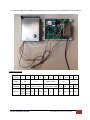
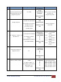
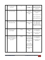
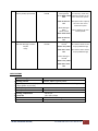
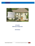
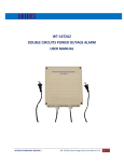
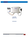
WT‐9002N
GSM Intercom
USER MANUAL
WITURA TECHNOLOGY SDN BHD |
WT‐9002N GSM Intercom User Manual
1
INTRODUCTION
The WT‐9002N is a GSM Intercom that comes with its own stainless steel external call point and when a
visitor at the gate presses the “call” button, the system will call the numbers programmed regardless of
the location of the telephone being called. The system can call up to 5 mobile phones or landline number in
the order they were programmed.
Once the owner has responded by answering the call, the visitor at the gate and the owner can have a
normal two way conversation voice communication. If the owner decides to allow the visitor to enter the
premises, all the owner has to do is use speed dial to call the gate and the gate will open without incurring
call costs.
The WT‐9002N is also an access control system. You can register up to 5 users into the system and if any
of these users calls the system, it will reject the call and open the gate without any cost of call. I f the
incoming call is not the registered user, the gate will not open.
The system uses a CE and FCC approved industry internal power supply connected on board. A
backup lithium battery can power up to 8 hours and will send a power down or power restored alerts in
the event of any circuit’s power failure.
The interface is housed in a back flanged IP 65 rated enclosure and can be located and fixed without
having to open the cover or requiring any internal fixings within the enclosure making a secure and
waterproof installation giving maximum protection of the control equipment inside.
The call point is a two piece fixing with the shield located and fixed and the main intercom fascia locked
into place and secured via the security fixing on the under frame of casing and again providing a very
secure vandal resistant and waterproof housing.
It is advised the distance from the interface to the call point does not exceed 3 meters.
WITURA TECHNOLOGY SDN BHD |
WT‐9002N GSM Intercom User Manual
2
It is recommended that the GSM Intercom be programmed to operate as required before final installation.
Connection Details
Connector
1
Label
3
J16
Description Line
Details
2
GND
5
J3
NO
6
7
8
Power Supply
Relay Output
Press Press
Button Button NC
Wire 1 Wire 2
WITURA TECHNOLOGY SDN BHD |
4
Com
9
10
11
J17
12
J18
Power Supply Input MIC ‐ MIC + SPK+
GND
N
L
MIC ‐
SPK‐
MIC + SPK + SPK ‐
WT‐9002N GSM Intercom User Manual
3
PREPARING THE SIM CARD
All new SIM cards have to be registered with the network provider before they can be used, usually by
calling the network provider or registering on their website please refer to the instructions supplied with
your SIM card.
During the registration procedure a confirmation code or text message is usually sent to the SIM cards
telephone number, to be able to read and react to the message you will need to insert the SIM card into an
unlocked mobile phone.
After successfully registering the SIM card, ensure there is sufficient credit on the card for programming
confirmation texts to be sent from the GSM Intercom.
You MUST ensure that the PIN request is disabled from the SIM card before inserting it into the GSM
Intercom. If you do not disable the PIN request the GSM Intercom will not work. If the PIN request is not
disabled and the unit is switched on more than 3 times you may have to reset the PIN using the PUK code
which will have to be obtained from the service provider.
To check the PIN request status of your SIM card, place the card in an unlocked mobile phone, switch the
phone on. If you are able to make calls without entering a PIN number the PIN request is disabled. If a PIN
number is requested refer to the instructions supplied with the SIM card and then look through the phones
options for the ‘disable PIN request’ and disable it.
You MUST disable any voicemail that is set up on the SIM card.
The SIM card is now ready to use.
Insert the SIM card and carefully close the carrier
When first booting up the system you will see green LED lights on the side of the enclosure and it should light
up when the network is applied to the unit.
The green LED is the network indicator and this will light up when attempting to log on to the network flash
inconsistently until it locates the network.
WITURA TECHNOLOGY SDN BHD |
WT‐9002N GSM Intercom User Manual
4
NO.
Description
1
Enter programming mode.
You only can perform the next
commands after enter into
programming mode.
SMS Programming Code
Example of SMS
Text Response
You get
administrator
privileges!
*0*1234#
Function
When you enter *0*1234#,
you enter into
programming mode.
2013‐10‐09 00:33
Wed
2
*0*1234*new password#
Change Password
For example if you need to
change to the new
password of 1212.
New
password<1212>
2013‐10‐10 16:07
Thu
Maximum 4 digits of
passwords
*0*1234*1212#
3
*1*1*telephone number#
Add telephone number into
the admin list.
For example set Admin
number
18617185300 into admin 2
*1*2*18617185300#
2013‐10‐10 16:08
Thu
4
Check phone number you
program in the list
Administrator:
1: 15989427391
2: 18617185300
3:
4:
5:
Administrator:
1: 15989427391
2: 18617185300
3:
4:
5:
*2*
Set Admin Numbers ;
*1*1* ‐ set 1st admin
number
*1*2* ‐ set 2nd admin
number
*1*3* ‐ set 3rd admin
number
*1*4* ‐ set 4th admin
number
*1*5* ‐ set 5th admin
number
.
2013019019 16:09
Thu
5
Delete an admin number
*3*N#
N = Admin number 1‐ 5
For example, if you want to
delete admin no 2.
just enter *3*2#
Administrator:
1: 15989427391
2:
3:
4:
5:
Delete Admin Number
Delete 1st admin *3*1#
Delete 2nd admin *3*2#
Delete 3rd admin *3*3#
Delete 4th admin *3*4#
Delete 5th admin *3*5#
2013019019 17:16
Thu
WITURA TECHNOLOGY SDN BHD |
WT‐9002N GSM Intercom User Manual V1.0
5
6
Check the relay status in ON
or OFF Mode.
*4*
Check Signal Strength
*5*
Master relay <ON> The unit will return Master
relay <ON> if the relay is
2013‐10‐10 16:10
on. The unit will return
Thu
Master relay <OFF> if the
relay is off.
7
CSQ<28>
If the signal is too weak, the
unit will not function
2013‐10‐10 16:11
properly.
Thu
CSQ 5 – 12 Signal too weak
CSQ 13‐ 24 Signal Good.
CSQ 25–32 Signal Excellent.
8
Time change OK!
Setting the year, month, day,
hours, minutes, week
*12*YYYYMMDDHHMMX#
SMS Message when the
system ON/OFF
*21*N#
YYYY=4 digit for year
MM = 2 digit for Month
2013‐10‐10 16:05
DD = 2 digit for Date
Thu
HH = 2 digit for Hour
MM = 2 digit for Minutes
X =1‐7(Day of the Week)
9
Message switch
<ON>
N=0 Message OFF
N=1 Message ON
2013‐10‐10 17:06
Thu
Factory Default as SMS
Message ON
After sending
command *22*0#
Status switch <OFF>
N=0 Message OFF
N=1 Message ON
10
To receive SMS Message or not
to receive SMS Message when
the system i s triggered by a
phone call
*22*N#
2013‐10‐10 17:10
Thu:
Factory Default as SMS
Message ON
After sending
command *22*1#
Master relay <ON>
2013‐10‐10 17:08
Thu:
WITURA TECHNOLOGY SDN BHD |
WT‐9002N GSM Intercom User Manual V1.0
6
11
Security mode/ Open Mode
*23*N#
When Setting as
Security Mode
N=1 Security mode. Only
*23*1# Mode switch allow the numbers in the
<ON>
list to control the system.
2013‐10‐10 17:13
Thu
When Setting as
Open
Mode *23*0#
Mode switch <OFF>
N=0 Open mode. Anybody
can call to the unit to
control the system.
Factory Default is N=1 for
Security Mode
2013‐10‐10 17:13
Thu
12
SMS Text Message to Switch
On/Off
Relay
*24*N#
When Setting as
*24*1#
N=1 means switch on the
Master relay <ON>
relay by SMS Message
2013‐10‐10 17:13
Thu
N=0 means switch off the
relay by SMS Message
When Setting as
*24*0#
Master relay <OFF>
2013‐10‐10 17:13
Thu
SPECIFICATIONS
Operation Voltage
12 volts DC
Operating Current
Maximum 500mA, typically 55mA
Relay Contacts 1 x Normally Open and Normally Closed Contacts maximum switching capacity
20 amps @230v ac per relay
GSM Frequency MHz
GSM 850, GSM 900, GSM 1800, GSM 1900
Humidity
Less Than 80% RH
Operating Temperature
‐20c to 55c
Physical Size
130 x 100 x 50mm
Protection
IP 65 Weather Proof Casing
Approvals
C.E, FCC, ETSI
WITURA TECHNOLOGY SDN BHD |
WT‐9002N GSM Intercom User Manual V1.0
7
FACTORY RESET
If you required you can rest the system by simply pressing the button “FACTORY” o n the control board until
you hear the “du~” . This indicates the unit back to the factory default
WITURA TECHNOLOGY SDN BHD |
WT‐9002N GSM Intercom User Manual V1.0
8
Warranty
Witura Technology Sdn Bhd warrantees the WT‐9002N GSM Intercom against defective parts and
workmanship. Witura Technology Sdn Bhd shall, at its option, repair or replace the defective equipment
upon the return of such equipment to any Witura branch. This warranty applies ONLY to defects in
components and workman‐ship and NOT to damage due to causes beyond the control of Witura, such as
incorrect voltage, lightning damage, mechanical shock, water damage, fire damage, or damage arising out of
abuse and improper application of the equipment.
Note: Wherever possible, return only the PCB to Witura Service Centres.
The WT‐9002N is a product of Witura Technology Sdn Bhd And is manufactured by
Shenzhen Witura Telecommunications Co., Ltd.
WARNING
For safety reasons, only connect equipment with a telecommunications compliance label. This includes
customer equipment previously labelled permitted or certified.
WITURA TECHNOLOGY SDN BHD |
WT‐9002N GSM Intercom User Manual V1.0
9