1
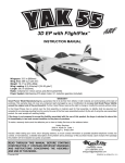
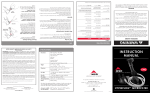
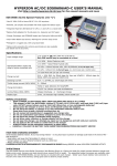
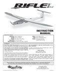
™
ELECTRIC DUCTED FAN INSTRUCTION MANUAL
Technical Data
Fan Swept Area: 2.71 in2 [17.5cm2]
Maximum rpm: 50,000 rpm
Housing Inner Diameter: 2.14 in [54.5mm]
Outer Diameter: 2.23 in [56mm]
Complete Assembly Weight (no motor): 1.3 oz [37g]
Welcome to the exciting world of Electric Ducted Fans (EDF)! The HyperFlow is a new EDF design created by Great Planes
using the latest technology to fit onto smaller EDF airplanes. The HyperFlow was created with ease of use in mind, as well as superior
performance using either a brushed or brushless motor. Great Planes offers several different motors that you can use to tailor the fan’s
performance to meet your needs. This EDF can fly airplanes as small as 10oz [280g] to airplanes as big as 35oz [990g] depending on
the chosen motor. Flying speeds have been measured to be from 55mph [88km/h] to 110mph [185km/h]. You can now fly modern jets
and fly them in a realistic manner–fast.
WARRANTY
Great Planes® Model Manufacturing Co. guarantees this product to be free from defects in both material and workmanship at the date of
purchase. This warranty does not cover any component parts damaged by use or modification. In no case shall Great Planes’ liability exceed
the original cost of the purchased product. Further, Great Planes reserves the right to change or modify this warranty without notice.
In that Great Planes has no control over the final assembly or material used for final assembly, no liability shall be assumed nor
accepted for any damage resulting from the use by the user of the final user-assembled product. By the act of using the user-assembled
product, the user accepts all resulting liability.
If the buyer is not prepared to accept the liability associated with the use of this product, the buyer is advised to return this product
immediately in new and unused condition to the place of purchase.
To make a warranty claim send the defective part or item to Hobby Services at the address below:
Hobby Services
3002 N. Apollo Dr. Suite 1
Champaign IL 61822 USA
Include a letter stating your name, return shipping address, as much contact information as possible (daytime telephone number, fax
number, e-mail address), a detailed description of the problem and a photocopy of the purchase receipt. Upon receipt of the package
the problem will be evaluated as quickly as possible.
Entire Contents © Copyright 2007
GPMZ0194 for GPMG3910/3911 V1.1
PERFORMANCE
The following measured performance data has been achieved using the stock intake lip and 90% FSA exhaust duct.
# LiPo Cells
Voltage
Current
Power
Motor: Brushed Speed 370BB (GPMG3910)
3
11.1V
10.3A
114W
Motor: Brushless 20-40-3500 (GPMG5140)
2
7.4V
8.7A
64W
3
11.1V
15.7A
174W
Motor: Brushless 24-33-4875 (GPMG5170)
2
7.4V
17.2A
127W
Motor: Brushless 24-45-3790 (GPMG5185)
2
7.4V
9.7A
72W
3
11.1V
19.9A
221W
4
14.8V
32.6A
482W
Static Thrust
RPM
Efflux
Speed
Efflux
Speed
240g (8.5oz)
29,000
(meters/second)
(miles/hour)
32 m/s
72 mph
215g (7.6oz)
400g (14.2oz)
27,000
35,800
28 m/s
46 m/s
63 mph
103 mph
330g (11.6oz)
32,300
41 m/s
92 mph
230g (8.0oz)
485g (17.1oz)
820g (28.9oz)
27,120
38,600
48,000
28 m/s
53 m/s
74 m/s
63 mph
118 mph
165 mph
Efflux Speed: Air Speed Exiting at the Exhaust
Please visit the Great Planes website (www.greatplanes.com) for performance
data on recently released motors or any other technical updates.
Hyperflow 56mm Measured Performance
TECHNICAL INFORMATION
180
160
Fan Swept Area
Efflux Speed (mph)
140
120
INTAKE
EXHAUST
100
Duct Cross-Section
80
60
40
20000
30000
40000
The way a ducted fan works is simple: As the fan rotates
and draws air, the surrounding duct causes the airflow to
accelerate through the fan and exit out of the exhaust tube.
With this in mind, fans are designed with a particular duct
profile in mind and a particular flying speed. The HyperFlow
has been designed to be most efficient while flying at 56 mph
[90 km/h]. This was done so that the fan would perform well
with an inexpensive brushed motor, but would still operate
at efficient levels with a brushless motor. This is proven by
the maximum measured thrust of 28.9oz and 165mph efflux
speed at 48,000rpm.
50000
RPM
30
25
Thrust (oz)
20
15
The duct profile is extremely important for the fan to perform
well. The intake needs to be large enough to supply the
required air to the fan at both low and high speeds and
at different rpm, but if the duct profile is too large, it may
increase the airplane's drag coefficient. Of course, the intake
and exhaust should be as short as possible to minimize
losses. The duct profile must be smooth and absolutely free
of obstacles. It is also recommended that the intake has a
smooth, rounded lip which helps maximize static thrust and
smooth airflow into the intake.
10
5
0
20000
30000
40000
50000
RPM
134% FSA
99% FSA
90% FSA
The data in these charts was obtained using
a stock intake lip. The motor was an Ammo
24-45-3790 and the ESC was an SS-35.
2
The fan swept area (FSA) is 2.74in2 [17.68cm2]. The minimum
intake area for this fan is 3.67in2 [23.6cm2]. This represents
134% of the FSA. This area can easily be achieved by using
a straight tube intake. Whenever possible, however, make
the intake as large as the model will aesthetically allow.
Exhaust area is equally important for the fan to perform well.
Using a straight-tube exhaust (134% FSA) will simplify the
construction of your duct, but at the cost of thrust and speed.
The optimum exhaust area for this fan is between 90 and
99% FSA (see graphs on the previous page). 99% FSA is
2.71in2 [17.5cm2] while 90% FSA is 2.46in2 [15.9cm2]. The
Hyperflow will deliver slightly more thrust at slower rpms
with 99% FSA, but in all other flight regimes, the 90% FSA
exhaust will deliver more thrust and speed.
ORDERING REPLACEMENT PARTS
Replacement parts for the Great Planes HyperFlow EDF are
available using the order numbers in the Replacement Parts
List that follows. The fastest, most economical service can
be provided by your hobby dealer or mail-order company.
To locate a hobby dealer, visit the Great Planes web site at
www.greatplanes.com. Choose “Where to Buy” at the top of
the page on the right side. Follow the instructions provided on
the page to locate a U.S., Canadian or International dealer.
Parts may also be ordered directly from Hobby Services by
calling (217) 398-0007, or via facsimile at (217) 398-7721,
but full retail prices and shipping and handling charges will
apply. Illinois and Nevada residents will also be charged
sales tax. If ordering via fax, include a Visa® or MasterCard®
number and expiration date for payment.
Useful Conversions:
134% FSA 3.67in2 [23.6cm2] = 2.162in [54.9mm] circle
99% FSA 2.71in2 [17.5cm2] = 1.857in [47.2mm] circle
90% FSA 2.46in2 [15.9cm2] = 1.769in [44.9mm] circle
Mail parts orders and payments by personal check to:
Hobby Services
3002 N Apollo Drive, Suite 1
Champaign IL 61822
KIT INSPECTION
Be certain to specify the order number exactly as listed
in the Replacement Parts List. Payment by credit card or
personal check only; no C.O.D.
Before starting to assemble, take an inventory of this kit
to make sure it is complete, and inspect the parts to make
sure they are of acceptable quality. If any parts are missing
or are not of acceptable quality, or if you need assistance
with assembly, contact Product Support. When reporting
defective or missing parts, use the part names exactly as
they are written in the Kit Contents list.
If additional assistance is required for any reason contact
Product Support by telephone at (217) 398-8970 or by
e-mail at [email protected]
Replacement Parts List
Order Number
GPMG3940
GPMG3941
GPMG3942
GPMG3943
Great Planes Product Support
3002 N Apollo Drive, Suite 1 Champaign, IL 61822
Telephone: (217) 398-8970, ext. 5 Fax: (217) 398-7721
E-mail: [email protected]
3
2
1
5
4
6
7
8
9
10
NOTE: Motor is only included in GPMG3911.
1. Ducted Fan Housing
2. Stator Extension
3. Aft Cone
4. Rotor Cone
5. Fan Rotor Blade
6. Front Housing Flange
7. 20mm Brushless Motor Adapter
8. Mounting Screws and Washer
9. Fan Rotor Adapters (2, 2.3, 3mm)
10. Motor
3
Description
Fan Rotor Blade
Miscellaneous Parts
Outer Duct
Rotor Adapter
DECISIONS YOU MUST MAKE
ASSEMBLY
At this point, based on the performance table from page 2
and the airplane you will install the HyperFlow ducted fan
into, you will need to decide which motor, ESC, and batteries
to use with the fan. Remember that once a motor is chosen
based on the power output, a speed controller and battery
must be used that are capable of delivering the current
drawn by the motor. Several power systems are available
from Great Planes at the time of this printing. Please check
www.electrifly.com for the most up-to-date information.
Installing a Brushed Motor
Brushed Power System:
Speed 370 BB Brushed Motor (GPMG0311)
ElectriFly C-25 ESC (GPMM2025)
ElectriFly 3-cell 910mAh LiPo (GPMP0605)
ElectriFly 3-cell 1250mAh LiPo (GPMP0609)
Brushless Power System:
ElectriFly Ammo 20-40-3500 Brushless Motor (GPMG5140)
ElectriFly Ammo 24-33-4875 Brushless Motor (GPMG5170)
ElectriFly Ammo 24-45-3790 Brushless Motor (GPMG5185)
ElectriFly SS 12A Brushless ESC (GPMM1810)
ElectriFly SS 25A Brushless ESC (GPMM1820)
ElectriFly SS 35A Brushless ESC (GPMM1830)
ElectriFly SS 45A Brushless ESC (GPMM1840)
ElectriFly 2-cell 910mAh LiPo (GPMP0604)
ElectriFly 3-cell 910mAh LiPo (GPMP0605)
ElectriFly 2-cell 1250mAh LiPo (GPMP0608)
ElectriFly 3-cell 1250mAh LiPo (GPMP0609)
ElectriFly 2-cell 1500mAh LiPo (GPMP0612)
ElectriFly 3-cell 1500mAh LiPo (GPMP0613)
ElectriFly 2-cell 2100mAh LiPo (GPMP0616)
ElectriFly 3-cell 2100mAh LiPo (GPMP0617)
ElectriFly 2-cell 3200mAh LiPo (GPMP0622)
ElectriFly 3-cell 3200mAh LiPo (GPMP0623)
❏ 1. If installing a Great Planes T-370 brushed motor, slide
the motor into the ducted fan housing up to the mounting
plate. Align the slotted motor mounting holes in the housing
with the screw holes at the top of the motor.
ADDITIONAL ITEMS REQUIRED
❏ Threadlocking compound (GPMR6060)
❏ Phillips screwdriver (HCAR1024)
❏ 1.5mm hex wrench (GPMR8010)
❏ Medium CA+ glue (GPMR6008)
The EP Ducted Fan Unit will work with 370 sized brushed
motors, 20mm brushless motors, and 24mm brushless
motors. All necessary parts are included for these motor
installations, plus 2mm, 2.3mm, and 3mm adapters.
Note: The aft cone might not be installed when using longer
brushless motors.
If your motor does not already have leads attached, do so
prior to the motor installation into the ducted fan unit.
NOTE: If the ducted fan application requires the fan housing
to be installed into an existing duct tube that provides properly
distributed airflow into the fan rotor, then the optional rotor cone
should not be installed. If the ducted fan is to be installed in a
nacelle or into a duct tube that does not properly direct airflow
into the fan rotor, the optional rotor cone should be installed.
❏ 2. Secure the motor to the fan housing using two 3 x 5mm
flat head screws with threadlocking compound.
4
❏ 4A. Fit the fan rotor over the brass fan adapter and push
it down so it is fully seated. If you will not be installing the
optional rotor cone, thread a 3 x 8mm Phillips screw with
a 3mm washer through the fan adapter. Be sure to use
threadlocking compound.
❏ 4B. If you are installing the optional rotor cone, press it
onto the fan rotor as shown. Insert a 3 x 8mm Phillips screw
and 3mm washer (with threadlocking compound) into the
hole in the rotor cone and tighten the screw into the brass
fan adapter.
❏ 3. Press the 2mm fan rotor adapter onto the motor. Using
threadlocking compound, tighten the set screws against the
motor shaft. Allow a small amount of clearance (1/8" [3mm])
between the base of the adapter and the motor to prevent
binding. A 3/32" [2.4mm] hole can be drilled into the side of
the fan housing 9/16" [14.3mm] from the front edge to insert
an allen wrench for the fan adapter set screws.
❏ 5. Cut a portion of the aft cone away for motor cooling and
to allow the motor leads to pass through. For most motor
applications, the aft cone should be approximately 1-1/4"
[32mm] long after cutting it.
5
IF INSTALLING A 24mm MOTOR (ONLY)
❏ 6. Attach the aft cone to the fan housing with a couple
drops of CA glue or tape. Excess glue will make it difficult to
remove the motor from the housing should it be necessary
in the future.
If installing a 24mm brushless motor, the three alignment
guides inside the fan housing must be trimmed prior to
inserting the motor (a hobby knife works; however, a rotary
tool such as a Dremel makes the job much easier). Slide
the motor into the housing, positioning the screw holes in
the motor with the slots in the mounting plate.
Installing a Brushless Motor
❏ 2. Secure the motor to the fan housing using two 3 x 5mm
flat head screws with threadlocking compound.
❏ 1. If installing a 20mm brushless motor, press the motor
adapter onto the rear of the motor can prior to sliding it into
the fan housing. The motor adapter is keyed to fit over the
three alignment guides inside the fan housing. Push the motor
up against the mounting plate, aligning the motor mounting
holes with the slots. Depending on the model motor being
used, you may need to cut away a part of the fan housing
in order for the motor to sit flush against the mounting plate.
Use the molded recess as a cutting guide.
❏ 3. There are brass fan rotor adapters provided for 2mm,
2.3mm, and 3mm motor shafts. Select the adapter that
fits your motor shaft and install the 3mm set screws with a
1.5mm wrench into the hexagonal base.
6
❏ 5B. If you are installing the optional rotor cone, press it onto
the fan rotor as shown. Insert a 3 x 8mm Phillips screw and
3mm washer (with threadlocking compound) into the hole in the
rotor cone and tighten the screw into the brass fan adapter.
❏ 4. Press the fan rotor adapter onto the motor and tighten
the set screws against the shaft. Allow a small amount of
clearance (1/8" [3mm]) between the base of the adapter and
the motor to prevent binding. A 3/32" [2.4mm] hole can be
drilled into the side of the fan housing 9/16" [14.3mm] from
the front edge to insert an allen wrench for the fan adapter
set screws.
❏ 6. Slide the stator extension onto the back of the ducted fan
housing. There are small notches on the stator extension that
fit around the fan housing. Be sure that the extension blades
are aligned with the stator blades inside the motor housing.
Secure the extension with a couple drops of CA glue.
❏ 7. Cut a portion of the aft cone away for motor cooling and
to allow the motor leads to pass through. For most motor
applications, the aft cone should be approximately 1-1/4"
[32mm] long after cutting it. If using a long brushless motor,
the aft cone may not fit and can be omitted. If you are going to
run a high power set-up, you can omit the aft cone to improve
motor cooling.
❏ 5A. Fit the fan rotor over the brass fan adapter and push
it down so it is fully seated. If you will not be installing the
optional rotor cone, thread a 3 x 8mm Phillips screw with
a 3mm washer through the fan adapter. Be sure to use
threadlocking compound.
7
• Ensure all persons in the immediate area are using eye
protection while the fan is in operation.
• NEVER point the fan in the direction of anyone.
• Make sure you inspect the fan and all its parts before
each run.
• Never use motors larger than those recommended.
• Never run a fan that is damaged in any way.
• Never run the fan while holding it in your hands.
• NEVER run the fan above 50,000 rpm!
• Never run the fan rotor on any motor outside of the housing.
❏ 8. Attach the aft cone to the fan housing with a few drops
of CA glue. Excess glue will make it difficult to remove the
motor from the housing should it be necessary in the future.
Install the Front Housing Flange
(Optional)
This is a device that runs at very high rpm and as such it
needs to be handled carefully. There is a very short “breakin” period that needs to be followed to ensure that all parts
fit well, everything is tight, and that no excessive vibration
is present when running the fan. Also, if the power system
chosen has a large power output, the fan blades will expand
as rpm are increased to the point of possibly touching the
housing. This is expected and it is within the “break-in”
procedures. The blades will get shortened slightly to fit the
fan housing as they wear on the sides.
The procedure below must be followed carefully:
1. If the fan is properly installed on an airframe and everything
is ready to be tested, arm the speed controller and advance
the throttle slowly to approximately 1/4 power for three
minutes. Check for vibration and/or unusual noises. If there
is vibration or unusual noise present during the test, do not
proceed to step 2 until the problem is resolved. Inspect all
moving parts, being sure that motor screws and the rotor
adapter screws are tight. Confirm that the fan blades rotate
smoothly within the housing and the rotor is not rubbing on
the mounting plate (Be sure to unplug the battery from the
ESC before handling the fan!).
2. If the fan operates smoothly, move the stick to 1/2 throttle
and repeat the test as described in step 1.
❏ For a nacelle installation, secure the front housing flange
to the fan housing using a couple drops of thin CA. The front
housing flange is not used on most internal fan installations
PREPARE TO RUN THE FAN
Before you run the fan make sure that:
• The motor selected is one of the recommended motors.
• An appropriate ESC is being used.
• An appropriate LiPo battery is being used.
• All the screws and set screws are secured with
threadlocking compound.
• All the fan parts are properly attached to the fan and to
the airframe.
• If any part of this fan should become damaged, replace all
parts. Never attempt to repair damaged parts.
• Keep the fan away from objects as it will try to suck them in,
which can cause damage to the fan and/or bodily injury.
• Always use eye protection when operating the fan unit.
• NEVER look into the fan as it is running.
3. Slowly advance the throttle to 3/4 power. When using highpower systems, the fan blades may rub a bit on the fan housing.
You can see this by powering down the system and checking
for marks or grooves in the housing. If this is the case, return
to 1/2 throttle and cycle between 1/2 throttle and 3/4 throttle
for three to four minutes. Doing so will adjust the length of the
fan blades as they slowly wear on the fan housing.
4. Repeat the procedure described in step 3 between 3/4
throttle and full throttle.
5. Unplug the battery from the ESC and check the fan for
rubbing, cracks, or missing parts.
If your fan appears damaged, vibrates excessively, or
makes unexpected noises, please return it to Hobby
Services for inspection.
Happy flying!