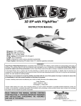
1
™
I N S T R U C T I O N
M A N U A L
SPECIFICATIONS
Wingspan: 52 in [1320 mm]
Wing Area: 449 in 2 [29 dm2]
Wing Loading: 26−28 oz/ft 2
[79−85 g /dm2 ]
Length:
Weight:
Radio:
Engine:
Electric Motor: RimFire™ .46-.55, 60A ESC
45 in [1145mm]
Battery: One 4S 3350mAh 14.8V LiPo
5 − 5.5 lb [2270−2490 g]
4-channel radio system with 5 servos
.46−.55 in 3 [7.45–9.0cc] two-stroke, .52 – .70 in 3 [8.5 – 11.1cc] four-stroke
WARRANTY
Great Planes ® Model Manufacturing Co. guarantees this kit to
be free from defects in both material and workmanship at the
date of purchase. This warranty does not cover any component
parts damaged by use or modification. In no case shall Great
Planes’ liability exceed the original cost of the purchased kit.
Further, Great Planes reserves the right to change or modify this
warranty without notice.
this kit immediately in new and unused condition to the
place of purchase.
To make a warranty claim send the defective part or item to
Hobby Services at the address below:
Hobby Services
3002 N. Apollo Dr. Suite 1
Champaign IL 61822 USA
In that Great Planes has no control over the final assembly or
material used for final assembly, no liability shall be assumed nor
accepted for any damage resulting from the use by the user of Include a letter stating your name, return shipping address, as
the final user-assembled product. By the act of using the much contact information as possible (daytime telephone
number, fax number, e-mail address), a detailed description of
user-assembled product, the user accepts all resulting liability.
the problem and a photocopy of the purchase receipt. Upon
If the buyer is not prepared to accept the liability associated receipt of the package the problem will be evaluated as quickly
with the use of this product, the buyer is advised to return as possible.
READ THROUGH THIS MANUAL BEFORE STARTING CONSTRUCTION. IT CONTAINS IMPORTANT
INSTRUCTIONS AND WARNINGS CONCERNING THE ASSEMBLY AND USE OF THIS MODEL.
Champaign, Illinois
(217) 398-8970, Ext 5
[email protected]
© 2013 Great Planes Model Mfg. A subsidiary of Hobbico, Inc.
GPMA1202 Mnl
TABLE OF CONTENTS
INTRODUCTION . . . . . . . . . . . . . . . . . . . . . . . . . . . . . . . . . . .2
Academy of Model Aeronautics . . . . . . . . . . . . . . . . . . . . . .2
SAFETY PRECAUTIONS . . . . . . . . . . . . . . . . . . . . . . . . . . . .2
DECISIONS YOU MUST MAKE. . . . . . . . . . . . . . . . . . . . . . . .3
Motor Battery Recommendations. . . . . . . . . . . . . . . . . . . . .3
Engine Recommendations . . . . . . . . . . . . . . . . . . . . . . . . . .3
Radio Equipment . . . . . . . . . . . . . . . . . . . . . . . . . . . . . . . . .3
ADDITIONAL ITEMS REQUIRED . . . . . . . . . . . . . . . . . . . . . .4
Required Hardware and Accessories. . . . . . . . . . . . . . . . . .4
Optional Supplies and Tools . . . . . . . . . . . . . . . . . . . . . . . . .4
IMPORTANT BUILDING NOTES . . . . . . . . . . . . . . . . . . . . . . .4
KIT INSPECTION. . . . . . . . . . . . . . . . . . . . . . . . . . . . . . . . . . .4
ORDERING REPLACEMENT PARTS . . . . . . . . . . . . . . . . . . .4
KIT CONTENTS . . . . . . . . . . . . . . . . . . . . . . . . . . . . . . . . . . . .5
TIGHTEN THE COVERING . . . . . . . . . . . . . . . . . . . . . . . . . . .6
INSTALL THE AILERON SERVOS . . . . . . . . . . . . . . . . . . . . .6
ASSEMBLE THE FUSELAGE . . . . . . . . . . . . . . . . . . . . . . . . .7
Install the Elevator and Rudder . . . . . . . . . . . . . . . . . . . . . .7
Mount the Main Landing Gear . . . . . . . . . . . . . . . . . . . . . . .9
Mount the Electric Motor . . . . . . . . . . . . . . . . . . . . . . . . . .10
Mount the Battery. . . . . . . . . . . . . . . . . . . . . . . . . . . . . . . .11
Install the Motor Cover and Spinner . . . . . . . . . . . . . . . . . .12
Mount the Fuel Tank . . . . . . . . . . . . . . . . . . . . . . . . . . . . . .13
Mount the Glow Engine . . . . . . . . . . . . . . . . . . . . . . . . . . .13
HOOK UP THE THROTTLE . . . . . . . . . . . . . . . . . . . . . . . . . .15
Two-Stroke Hookup . . . . . . . . . . . . . . . . . . . . . . . . . . . . . .15
Install the Fuel Line . . . . . . . . . . . . . . . . . . . . . . . . . . . . . .16
Four-Stroke Hookup . . . . . . . . . . . . . . . . . . . . . . . . . . . . . .16
FINAL ASSEMBLY . . . . . . . . . . . . . . . . . . . . . . . . . . . . . . . .16
Final Radio Installation . . . . . . . . . . . . . . . . . . . . . . . . . . . .16
Install the Propeller and Spinner . . . . . . . . . . . . . . . . . . . .17
Install the Wings . . . . . . . . . . . . . . . . . . . . . . . . . . . . . . . . .18
Apply the Decals . . . . . . . . . . . . . . . . . . . . . . . . . . . . . . . .18
GET THE MODEL READY TO FLY . . . . . . . . . . . . . . . . . . . .18
Install and Connect the Motor Battery . . . . . . . . . . . . . . . .18
Check the Control Directions . . . . . . . . . . . . . . . . . . . . . . .19
Set the Control Throws. . . . . . . . . . . . . . . . . . . . . . . . . . . .19
Balance the Model (C.G.) . . . . . . . . . . . . . . . . . . . . . . . . . .20
Balance the Model Laterally . . . . . . . . . . . . . . . . . . . . . . . .21
PREFLIGHT . . . . . . . . . . . . . . . . . . . . . . . . . . . . . . . . . . . . . .21
Identify Your Model . . . . . . . . . . . . . . . . . . . . . . . . . . . . . . .21
Charge the Batteries . . . . . . . . . . . . . . . . . . . . . . . . . . . . .21
Balance the Propellers . . . . . . . . . . . . . . . . . . . . . . . . . . . .21
Ground Check and Range Check. . . . . . . . . . . . . . . . . . . .22
ENGINE SAFETY PRECAUTIONS . . . . . . . . . . . . . . . . . . . .22
AMA SAFETY CODE. . . . . . . . . . . . . . . . . . . . . . . . . . . . . . .22
General. . . . . . . . . . . . . . . . . . . . . . . . . . . . . . . . . . . . . . . .22
Radio Control . . . . . . . . . . . . . . . . . . . . . . . . . . . . . . . . . . .22
CHECK LIST . . . . . . . . . . . . . . . . . . . . . . . . . . . . . . . . . . . . .23
FLYING. . . . . . . . . . . . . . . . . . . . . . . . . . . . . . . . . . . . . . . . . .23
Fuel Mixture Adjustments. . . . . . . . . . . . . . . . . . . . . . . . . .23
Takeoff . . . . . . . . . . . . . . . . . . . . . . . . . . . . . . . . . . . . . . . .23
Flight. . . . . . . . . . . . . . . . . . . . . . . . . . . . . . . . . . Back Cover
Landing. . . . . . . . . . . . . . . . . . . . . . . . . . . . . . . . Back Cover
INTRODUCTION
SAFETY PRECAUTIONS
For the latest technical updates or manual corrections to the
Escapade MX ARF visit the Great Planes web site at www.
greatplanes.com. Open the “Airplanes” link, then select the
Escapade MX ARF. If there is new technical information or
changes to this model a “tech notice” box will appear in the
upper left corner of the page.
Protect Your Model, Yourself & Others…
Follow These Important Safety Precautions
1. Your Escapade should not be considered a toy, but rather a
sophisticated, working model that functions very much like
a full-size airplane. Because of its performance capabilities,
the Escapade could possibly cause injury to yourself or
spectators and damage to property if not assembled and
operated correctly.
Academy of Model Aeronautics
2. You must assemble the model according to the instructions.
Do not alter or modify the model, as doing so may result in
an unsafe or unflyable model. In a few cases the instructions
may differ slightly from the photos. In those instances the
written instructions should be considered as correct.
If you are not already a member of the AMA, please join! The
AMA is the governing body of model aviation and membership
provides liability insurance coverage, protects modelers’ rights
and interests and is required to fly at most R/C sites.
Academy of Model Aeronautics
5151 East Memorial Drive
Muncie, IN 47302-9252
3. You must take time to build straight, true and strong.
Or via the Internet at: http://www.modelaircraft.org
4. You must use an R/C radio system that is in good condition,
a correctly sized engine, and other components as specified
in this instruction manual. All components must be correctly
installed so that the model operates correctly on the ground
and in the air. You must check the operation of the model
and all components before every flight.
IMPORTANT!!! Two of the most important things you can
do to preserve the radio controlled aircraft hobby are to avoid
flying near full-scale aircraft and avoid flying near or over
groups of people.
5. If you are not an experienced pilot or have not flown this
type of model before, we recommend that you get the
assistance of an experienced pilot in your R/C club for
your first flights. If you’re not a member of a club, your
Tele. (800) 435-9262
Fax (765) 741-0057
2
Following are the other suggested items if powering your
Escapade with an electric motor:
local hobby shop has information about clubs in your area
whose membership includes experienced pilots.
6. While this kit has been flight tested to exceed normal use,
if the plane will be used for extremely high stress flying,
such as racing, or if an engine larger than one in the
recommended range is used, the modeler is responsible
for taking steps to reinforce the high stress points and/or
substituting hardware more suitable for the increased stress.
❍ Suitable propeller and spare propellers (APC 11 x 7
APCQ4128)
❍ 8mm prop reamer (for propellers and included spinner
– GPMQ5007)
7. WARNING: The cowl and wheel pants included in this kit
are made of fiberglass, the fibers of which may cause eye,
skin and respiratory tract irritation. Never blow into a part
(wheel pant, cowl) to remove fiberglass dust, as the dust
will blow back into your eyes. Always wear safety goggles,
a particle mask and rubber gloves when grinding, drilling
and sanding fiberglass parts. Vacuum the parts and the
work area thoroughly after working with fiberglass parts.
If powering your Escapade with an engine:
Engine Recommendations
The recommended engine size range for the Escapade is
.46 to .55 two-stroke or .52 to .70 four-stroke. If an engine in
the upper end of the size range is used, responsible throttle
management should be practiced.
We, as the kit manufacturer, provide you with a top quality,
thoroughly tested kit and instructions, but ultimately the
quality and flyability of your finished model depends
on how you build it; therefore, we cannot in any way
guarantee the performance of your completed model,
and no representations are expressed or implied as to the
performance or safety of your completed model.
❍ O.S.® 55AX ABL w/Muffler (OSMG0557)
❍ (1) APCQ1107 APC 11x7 Sport Propeller
❍ 3' Great Planes Silicone Fuel Tubing (GPMG4131)
❍ (1) Great Planes Aluminum Fuel Line Plug (GPMQ4166)
Remember: Take your time and follow the instructions to
end up with a well-built model that is straight and true.
Fuel, fueling system (pump, fuel line, fuel can fittings set),
1.5V glow driver, field box, tools
DECISIONS YOU MUST MAKE
Radio Equipment
This is a partial list of items required to finish the Escapade
that may require planning or decision making before starting
to build. Order numbers are provided in parentheses.
4-channels are required to fly the Escapade. However, the
number of servos required is five. Only four servos will be
required if flying the Escapade with an electric motor. If powering
the model with a glow engine, a servo will be required for the
throttle. And in either case (glow or electric), two servos will
be required for the aileron. In all cases, standard-size servos
with standard output torque (40 – 50 oz-in torque) are suitable.
If powering your Escapade with an electric motor:
Following is the specific radio gear required:
Motor Battery Recommendations
❍ 4-channel radio system w/4.8V 500-600mAh flat Rx
battery back, on/off switch
If powering your Escapade with an electric motor, it performs
superbly on a:
❍ RimFire™ .55 motor (GPMG4715)
❍ (2) ea. standard size/40 oz-in torque elevator and
rudder servo
❍ One 4S 3350mAh 14.8V LiPo batteries. (FlightPower®
EONX™ 30 3350 mAh 4s 14.8V 30C LiPo FPWP6356)
❍ (1) standard size/40 oz-in torque throttle servo
❍ (2) standard size/40 oz-in torque aileron servos
❍ ElectriFly® Series 2 Deans® Male Ultra Plug ® / 1 Deans
Female Ultra Plug Adapter
❍ (2) 6" [152mm] servo extension wires
(HCAM2711 for Futaba®)
❍ GPMM3155 Great Planes ElectriFly Triton™ EQ AC/
DC Charger
❍ (1) Dual servo extension (FUTM4130 for Futaba)
If experimenting with different batteries, make certain they
are rated for at least a 30C discharge.
A 60A ESC (electronic speed controller) is also required. The
ElectriFly Silver Series 60A Brushless ESC (GPMM1850) is
recommended.
3
without using any glue, then slightly modify or custom fit
the part as necessary for the best fit.
ADDITIONAL ITEMS REQUIRED
● Whenever the term glue is written you should rely upon
your experience to decide what type of glue to use. When
a specific type of adhesive works best for that step, the
instructions will make a recommendation.
Required Hardware and Accessories
This is the list of hardware and accessories required to finish
the Escapade. Order numbers are provided in parentheses.
● Whenever just epoxy is specified you may use either
30-minute (or 45-minute) epoxy or 6-minute epoxy. When
30-minute epoxy is specified it is highly recommended that
you use only 30-minute (or 45-minute) epoxy, because you
will need the working time and/or the additional strength.
❍ Phillips screwdriver
❍ 1/2 oz. [15g] Medium Pro™ CA+ (GPMR6007)
❍ 1/2 oz. [15g] Thin Pro CA (GPMR6001)
❍ CA applicator tips (HCAR3780)
❍ #1 Hobby knife (HCAR0105)
❍ #11 Blades (5-pack, HCAR0211)
❍ Power drill
❍ Drill bits; 1/16" [1.6mm], 3/32" [2.4mm],13/64" [5.2mm],
3/16" [4.8mm] #29 (or 9/64" [3.6mm]). #48 (.076"
[1.9mm]) drill or hobby knife
❍ Great Planes Pro Threadlocker (GPMR6060)
❍ 21st Century® sealing iron (COVR2700)
❍ Side cutters
❍ Crescent wrench
❍ Clear tape
❍ Felt-tip marker
● Photos and sketches are placed before the step they refer
to. Frequently you can study photos in following steps to
get another view of the same parts.
● The Escapade is factory-covered with Top Flite® MonoKote®
film. Should repairs ever be required, MonoKote can be
patched with additional MonoKote purchased separately.
MonoKote is packaged in six-foot rolls, but some hobby
shops also sell it by the foot. If only a small piece of MonoKote
is needed for a minor patch, perhaps a fellow modeler
would give you some. MonoKote is applied with a model
airplane covering iron, but in an emergency a regular iron
could be used. A roll of MonoKote includes full instructions
for application. Following are the colors used on this model
and order numbers for six foot rolls.
Optional Supplies and Tools
Jet White
Orange
Purple
Metallic Charcoal
Here is a list of optional tools mentioned in the manual that
will help you build the Escapade.
❍ 21st Century iron cover (COVR2702)
❍ 21st Century trim seal iron (COVR2750)
❍ Stick-on segmented lead weights (GPMQ4485)
❍ 2 oz. [57g] Spray CA activator (GPMR6035)
❍ Dead Center™ Engine Mount Hole Locator
(GPMR8130)
❍ C.G. Machine™ (GPMR2400)
❍ Moto-tool
❍ Precision Magnetic Prop Balancer (TOPQ5700)
TOPQ0204
TOPQ0202
TOPQ0225
TOPQ0407
KIT INSPECTION
Before starting to build, take an inventory of this kit to make
sure it is complete, and inspect the parts to make sure they
are of acceptable quality. If any parts are missing or are not
of acceptable quality, or if you need assistance with assembly,
contact Product Support. When reporting defective or missing
parts, use the part names exactly as they are written in the
Kit Contents list.
IMPORTANT BUILDING NOTES
Great Planes Product Support
3002 N Apollo Drive, Suite 1 Ph: (217) 398-8970, ext. 5
Champaign, IL 61822
Fax: (217) 398-7721
● There are two types of screws used in this kit:
Self-Tapping Screws are designated by a number and
a length. For example #6 × 3/4" [19mm].
E-mail: [email protected]
This is a number six screw
that is 3/4" [19mm] long.
ORDERING REPLACEMENT PARTS
Machine Screws are designated by a number, threads
per inch, and a length. For example
4-40 × 3/4" [19mm].
Replacement parts for the Great Planes Escapade MX ARF
are available using the order numbers in the Replacement
Parts List that follows. The fastest, most economical service
can be provided by your hobby dealer or mail-order company.
This is a number four screw
that is 3/4" [19mm] long with
forty threads per inch.
To locate a hobby dealer, visit the Great Planes web site at
www.greatplanes.com. Select “Where to Buy” in the menu
across the top of the page and follow the instructions provided
to locate a U.S., Canadian or International dealer.
● When you see the term test fit in the instructions, it means
that you should first position the part on the assembly
4
Parts may also be ordered directly from Hobby Services by
calling (217) 398-0007, or via facsimile at (217) 398-7721, but
full retail prices and shipping and handling charges will apply.
Illinois and Nevada residents will also be charged sales tax. If
ordering via fax, include a Visa® or MasterCard® number and
expiration date for payment.
REPLACEMENT PARTS LIST
Order No.
GPMA2000
GPMA2001
GPMA2002
GPMA2003
GPMA2004
GPMA2005
GPMA2006
GPMA2007
GPMA2008
GPMA2009
GPMA2010
GPMA2011
GPMA2012
Mail parts orders and payments by personal check to:
Hobby Services
3002 N Apollo Drive, Suite 1
Champaign IL 61822
Be certain to specify the order number exactly as listed in the
Replacement Parts List. Payment by credit card or personal
check only; no C.O.D.
If additional assistance is required for any reason, contact
Product Support by e-mail at productsupport@greatplanes.
com, or by telephone at (217) 398-8970.
Description
Wing Escapade Mx ARF
Fuselage Escapade Mx ARF
Horizontal Stabilizer Escapade Mx ARF
Vertical Stabilizer Mx Escapade ARF
Canopy Escapade Mx ARF
Wheelpants Escapade Mx ARF
Landing Gear Escapade Mx ARF
Spinner Escapade Mx ARF
Motor Cover Escapade Mx ARF
Motor Mount Escapade Mx ARF
Decals Escapade Mx ARF
Wing Tube Escapade Mx ARF
Wing Bolts Escapade Mx ARF
KIT CONTENTS
3
1
12
13
11
10
9
8
4
6
2
7
14
5
5
1. Fuselage
6. Wheel Pants
11. Fuel Tank
2. Motor Cover
7. Wheels
12. Electric Motor Mount
3. Fin and Rudder
8. Landing Gear
13. Tail Wheel Assembly
4. Stabilizer and Elevator
9. Nylon Engine Mount
14. Wing Tube
5. Right and Left Wings
10. Spinner
5
TIGHTEN THE COVERING
Refer to the separate instruction sheet titled How To Tighten
Covering On ARF Models. Follow the instructions to tighten
the covering. If you prefer to get started on assembly right
away, the tightening process could be done later (but it is
usually easiest to do while the model is still in separate pieces).
INSTALL THE AILERON SERVOS
❏ ❏ 3. Temporarily mount the servo with the screws that came
with it. Drill 1/16" [1.6mm] holes for the servo mounting screws.
Remove the screws and take out the servo. Add a few drops of
thin CA to each screw hole. Wait a minute for the CA to harden
and remount the servo. Don’t over tighten the servo mounting
screws—just make sure the heads of the screws apply a little
pressure to the grommets and that the servo is secure.
❏ ❏ 1. Connect a 6" [152mm] servo extension to the aileron
servo and secure the connection with a 1-1/2" [40mm] piece
of heat shrink tubing included with this kit—shrink the tubing
with a heat gun, match or a hobby torch—use care not to
scorch the wires!
90°
NO
NO
YES
Cut off the
unused arms.
❏ ❏ 4. Temporarily connect the servo to the receiver with
the battery and switch. Turn on the transmitter and receiver
and center all the trims on the transmitter. With the radio on,
fit the servo arm onto the splined output shaft so it will be 90°
as shown in the sketch.
Left Wing
Right Wing
❏ ❏ 5. Note the position of the servo arms in the sketch. Cut
off the unused arm(s) from each aileron servo arm.
❏ ❏ 2. Use the string in the wing to pull the servo extension
out the end and place the aileron servo in the wing.
6
ASSEMBLE THE FUSELAGE
Install the Elevator and Rudder
❏ ❏ 6. Thread a nylon clevis approximately 20 turns onto the
threaded end of the 2-56 x 6" [152mm] wire and then slide
a silicone clevis keeper onto the wire. Install the clevis into
the control arm as shown in the photograph. Slide the clevis
keeper over the clevis.
❏ ❏ 7. Making sure the servo and the aileron are centered,
use a fine-point felt-tip pen to mark the pushrod wire where
it crosses the outer hole in the servo arm.
❏ 1. Cut the balsa block free from the stabilizer opening with
a hobby knife.
❏ ❏ 8. Make a 90° bend in the wire at the mark. Fit the
pushrod into the outer hole in the servo arm and then attach
a 90° pushrod connector to the assembly. Cut the excess wire
1/16" [2mm] above the connector. Install the servo arm screw
and slip the silicone retainers over the pushrod.
❏ 2. Slide the horizontal stabilizer (stab) into the stab opening
in the back of the fuselage.
❏ 9. Repeat steps 1– 8 for the other wing.
7
Add a drop of threadlocker to the threads of the wires. Then,
tighten the assembly to the fuselage with #4 flat washers and
a 4-40 lock nut on each rod. The included socket tool may be
used to tighten the nuts. These should be snug, but do not
overtighten and crush the stab.
❏ 5. Mount the tail gear assembly in the following order:
❏ A. Assemble the tail gear as shown. It may be necessary
to add a small amount of CA to the retainer.
❏ B.
Add a small drop of threadlocker to the threads on
the 4-40 set screw for the wheel collar. Then, thread
the set screw into the wheel collar. Fit the tail gear
wire through the hole in the strap, then the collar, but
don’t tighten the set screw yet.
❏ C.
Fit the assembly into the bushing in the fuselage.
❏ 3. Slide the vertical fin (fin) into the opening in the top of
the fuselage, guiding the threaded wires into the holes in the
bottom of the fuselage. Make sure the fin is fully seated in the
fuselage and in the stab.
❏ 4. Even though the nuts used on the fin wires are locking
nuts, a drop of threadlocker on the threads is recommended.
8
❏ D.
Using the holes in the strap as a guide, drill 1/16"
[1.6mm] holes into the bottom of the fuselage. Install,
then remove two #2 x 3/8" [9.5mm] self-tapping screws
into the holes, apply a few drops of thin CA to the holes,
allow to harden, and remount the strap with the screws.
❏ E.
Push the tail wheel’s guide wire through the guide post
on the rudder and push the tail wheel post through
the strap and wheel collar.
❏ F.
Tighten the set screw in the collar.
❏
10. Place the elevator servo into the servo tray in the
fuselage. Orient it as shown in the photo. Same as you did with
the rudder servo, connect the elevator servo to your receiver
and battery and turn on the radio. Center the trims and find
the correct orientation for the servo arms that will be 90°. Cut
off the unused arms.
Mount the Main Landing Gear
❏ 6. Thread a nylon clevis onto the 27" pushrod wire 20
turns. Slide the elevator and rudder pushrods into the guide
tubes in the rear of the fuselage. Connect the clevises to the
second-from-the-outer holes of the horns. Slide the silicone
retainers over the clevises.
❏ 7. Place the rudder servo in the servo tray in the fuselage.
Same as you did with the aileron servos, connect the rudder
servo to your receiver and battery and turn on the radio. Center
the trims and find the correct orientation for the servo arms
that will be 90°. Cut off the unused arms.
❏ 1. Using threadlocker, mount the landing gear to the fuselage
with four 6-32 x 1/2" [13mm] machine screws and #6 lock washers.
❏ 8. Mark, cut, bend and connect the pushrod to the servo the
same way you did for the ailerons. After you mark the pushrods,
it will be easier to bend and cut them if you disconnect the
clevises from the horns on the other end.
❏ 9. The same way you mounted the aileron servo(s), mount ❏ 2. Mount an axle to each landing gear, securing it with
the rudder servo with the servo screws that came with them. the locking axle nut. Be sure that the flat spot on the end of
Don’t forget to harden the screw holes with a few drops of thin the axle is towards the bottom of the model. Add four #6 flat
washers to each axle.
CA after installing, then removing the screws.
9
❏ 2. Mount the plywood electric motor mount to the front of
❏ 3. Mount the wheels to the axles with a 5/32" [4mm] collar
the fuselage with four 6-32 x 3/4" [19mm] machine screws,
#6 lock washers and #6 flat washers. Be sure to use a few
drops of threadlocker on the threads of each screw.
on both sides held on with the set screws and threadlocker
on the threads.
❏ 4. Mount each wheel pant to the landing gear with two
4-40 x 3/8" [10mm] machine screws, #4 flat washers and lock
washers. Be sure to use threadlocker on the threads.
❏ 3. On the bottom of the plywood electric motor mount you
will find two mounting holes for the Great Planes 60 amp ESC
(GPMM1850). Drill a 1/16" [1.6mm] hole in the location shown
at the back of the mount. Insert and then remove a #3 x 3/8"
[10mm] self-tapping screw through each hole and then harden
the threads with a couple of drops of thin CA glue. If you are
using a different brand ESC, then drill mounting holes as needed.
Proceed to “Mount the Glow Engine” if you will not be
installing the electric motor.
Mount the Electric Motor
❏ 4. Mount the ESC with #3 x 3/8" [10mm] self-tapping screws
❏ 1. Use a small saw and hobby knife (or Moto-Tool) to knock out
the air inlet in the firewall for the electric motor mount installation.
10
and #4 flat washers. Feed the connectors through the hole
in the bottom of the motor mount and the firewall so that the
connectors are inside the fuselage.
Mount the Battery
IMPORTANT: If powering your Escapade with an electric
motor, before experimenting with different motor battery
combinations and connecting multiple battery packs with
adapter plugs, refer to the Battery Precautions on page 22.
❏ 5. Use a side cutter or Moto-Tool to cut the screws flush
with the surface of the plywood.
❏ Cut pieces of the self-adhesive hook-and-loop material and
place the hook side as shown. Each of your battery packs
should have the a strip of the loop material on them to hold
the battery in place. Slide the nonadhesive hook-and-loop
straps into the slots in the tray as shown. When you insert the
battery into the fuselage, tighten the straps around the battery.
❏ 6. Mount the motor to the motor mount with four 6-32 x 1/2"
[13mm] machine screws, #6 washers and #6 lock washers.
Be sure to apply a drop of threadlocker to each screw. Plug
the motor into the ESC.
11
Install the Motor Cover and Spinner
❏ 3. Next use clear tape to secure the brushless cover’s sides
to the fuselage sides.
❏ 1. Place the included balsa stick on the nose of the Escapade ❏ 4. Use a felt tipped marker to mark the locations for the
brushless cover’s securing screws which will go through the
brushless cover and into the plywood stick.
MX as shown. Test fit the brushless cover so that it lines up
with the trim on the aircraft. It may be necessary to remove the
balsa stick and trim the length so that the brushless cover’s
width fits properly with the aircraft’s nose.
❏ 5. Using a 1/16 drill bit, drill the two holes. Remember to
tap the two holes and use thin CA to harden the plywood.
Install the two #2 x 3/16" self-tapping screws along with the
#4 washers.
❏ 2. Once you’ve achieved a good fit, use CA to secure the
stick in the position on the nose.
12
screw in the stopper assembly a few turns and temporarily
remove the stopper assembly from the tank. Be certain the
vent tube is toward the top of the tank. Then, reinsert the
stopper assembly and tighten the screw to squish the rubber
stopper and seal the tank.
❏ 6. Mount the spinner backplate and a balanced propeller
to the motor with the washer and nut included with the motor.
Then, mount the spinner cone with the self-tapping screws
that came with the spinner.
Proceed to Final Assembly.
❏ 3. Feed the fuel lines and stopper through the opening in
the firewall. Mount the fuel tank with the strap.
Mount the Fuel Tank
❏ 1. Slide one hook-and-loop strap into the forward slot in
Mount the Glow Engine
the tray.
Before following these mounting instructions you
should determine your engine or motor of choice and
familiarize yourself with the instructions. Read through
the instructions, decide which method you will use and
then proceed to mount the engine
Top
❏ 1. Temporarily mount the two-piece engine mount to the
fuselage with four 6-32 x 1" [25.4mm] machine screws, four
#6 lock washers and #6 flat washers, but don’t tighten the
screws all the way yet.
Vent Tube
❏ 2. Place your engine on the mount, sliding the mount halves
together or apart to fit the engine. Now you may tighten the
mount bolts the rest of the way.
❏ 2. Use a fine-point felt-tip pen to write “TOP” on the same side
of the fuel tank that has the clear fuel line. Loosen the Phillips
13
❏ 3. Use a marker to mark the position for the throttle pushrod
❏
5. Use a Great Planes Dead Center™ Hole Locator
(GPMR8130) or a sharpened wire to mark the location of
the engine mounting holes onto the mount.
as shown on the firewall pictured. Use a 13/64” drill bit to drill
through the firewall. Be careful not to drill into the fuel tank.
❏ 6. Drill #29 (or 9/64" [3.6mm]) holes through the engine
mount at the marks you made for the mounting screws. Mount
the engine with four 6-32 x 3/4" [19mm] machine screws and
#6 lock washers. Use an 6-32 tap to tap threads into the holes
after drilling them. Then, use 6-32 x 3/4" machine screws and
#6 lock washers for mounting the engine. Note: Four-stroke
engines may have to be temporarily dismounted later while
hooking up the throttle.
❏ 7. Some engines may need to have clearance for the needle
valve. Cut clearance in the fuselage as needed for your engine.
❏ 4. Use a propeller reamer or correctly sized drill to enlarge
the hole in your propeller and in the spinner backplate to
fit your engine. Place the backplate of the spinner on the
engine and position the engine on the mount so there will be
a maximum 1/8" [3mm] space between the backplate of the
spinner and the front of the fuselage. Note: Most 4-stroke
engines will not be able to be positioned far enough aft on
the mount to achieve this spacing, so just move the engine
as far back as possible.
14
the servo bay. Cut the nylon pushrod tube so it extends from
the firewall by at least 1/4" [6mm]. Roughen the end of the
tube with 180 grit sandpaper. Apply a couple of drops of CA
glue where the tube passes through the firewall and formers.
HOOK UP THE THROTTLE
90° Pushrod Connector
Throttle Guide Tube
Carburetor
Arm
Firewall
❏ 1. Using a 1/16" drill bit, drill four holes for the throttle servo
tray. Install the tray using four #3 x 3/8" self-tapping screws.
Remember to use thin CA to harden the threads in the wood.
Throttle
Servo
Clevis
❏ 2. Hook up the throttle using the 20" [508mm] pushrod
and a nylon clevis on the carburetor arm. The location of the
carburetor arm may vary between engine brands so you may
need to cut a new hole in the firewall for the guide tube that
aligns with your carburetor arm. If you do, mark the location
of the new hole, remove the engine if necessary, and then
use an extended 3/16" [4.8mm] drill (available at hardware
or home improvement stores) or a 3/16" [4.8mm] brass tube
sharpened on the end to cut a new hole in the firewall. Install
a nylon clevis onto the threaded end of the pushrod wire
approximately 20 turns. Slide a silicone clevis keeper over
the clevis. Install the pushrod wire into the pushrod tube and
attach the clevis to the carburetor arm.
❏ 2. Install a servo arm onto the throttle servo. Place the throttle
servo into the fuselage. Slide the 20" [508mm] pushrod wire
through the hole in the firewall and into the fuselage. Align
the hole at the end of the arm with the pushrod wire. Using
the hardware that came with your servo, mount the servo to
the tray. Once the throttle is installed remove the pushrod wire.
Two-Stroke Hookup
❏ 3. Connect the throttle pushrod to the throttle servo using
a nylon Faslink in the same way as you did with the ailerons.
❏ 1. Install the 17-3/4" [450mm] nylon pushrod tube through
the hole in the firewall, along the side of the fuel tank and into
15
FINAL ASSEMBLY
Install the Fuel Line
Final Radio Installation
Vent / Overflow
(Connect to
fitting on Muffler)
One line is for Fueling and Defueling. The other line goes
to the Carburetor. It doesn’t matter which line goes where
because they are both the same inside the fuel tank.
❏ Mount the muffler to your engine and connect the fuel lines
to the fuel tank as shown in the diagram. The line with the fuel
line plug goes to either of the “clunk” lines on the fuel tank
that will be used for fueling and defueling the tank (this line
must be plugged after fueling).
❏ 1. Install the Rx/battery tray in the fuselage using four
#3 x3/8" self-tapping screws and four #4 washers.
Proceed to “Final Assembly” on page 20
Four-Stroke Hookup
❏ 2. Wrap both the Rx battery and the receiver in 1/4" [6mm]
R/C foam rubber. Make a strap from the included hook-andloop material to mount the battery and the receiver to the
receiver tray as shown.
❏ 1. Install the screw-lock connector (not included) onto the
throttle arm as shown. Cut the threaded portion off of the 20"
[508mm] pushrod and then bend a 3/4" [19mm] radius loop
on one end of the wire. Slide the wire into the pushrod tube
and the screw lock connector. Secure the wire to the screw
lock connector with the set screw. NOTE - The location of the
carburetor arm may vary between engine brands so you may
need to cut a new hole in the firewall for the guide tube that
aligns with your carburetor arm. If you do, mark the location
of the new hole, remove the engine if necessary, and then
use an extended 3/16" [4.8mm] drill (available at hardware
or home improvement stores) or a 3/16" [4.8mm] brass tube
sharpened on the end to cut a new hole in the firewall.
❏ 2. Connect the throttle pushrod to the throttle servo using ❏ 3. If using a 2.4GHz receiver, use the included tube to
a nylon Faslink in the same way as you did with the ailerons.
16
mount one of the antennas to the formers as shown.
new holes). Note: For glow engines the switch should be
mounted on the side of the fuselage opposite the muffler. Cut
the covering from the switch mount holes and mount the on/
off switch. Then connect the switch to the radio and battery.
Install the Propeller and Spinner
❏ 4. The second 2.4GHz antenna can be routed down and
out the bottom of the fuselage or out of the floor of the canopy.
If using a 72MHz receiver, guide the antenna down through
the back of the fuselage.
❏ 1. Install the spinner back plate and propeller onto the engine.
Temporarily install the prop washer and prop nut. Fit the spinner
cone to the spinner back plate. The screws for the spinner cone
need to align with the screw holes in the back plate. Depending
on your choice of engine and propeller the holes will most likely
not align correctly. If this is the case, cut the alignment pins from
the spinner back plate with a sharp hobby knife.
❏ 2. Install the modified back plate, propeller and spinner
cone. Secure the spinner cone to the backplate with the two
self-tapping screws included with the spinner.
❏ 5. Of the two switch mounting locations pre-cut into the
fuselage sides, determine which one you will use for mounting
the on/off switch for the receiver as well as the battery charge
jack (or, if none of these is suitable, use the switch mounting
plate that came with your switch as a template for cutting
17
Install the Wings
❏ 4. Insert the other aileron servo extension into the dual
servo extension. Use heat shrink tubing to secure the servo
connections to the dual servo extension.
❏ 1. Insert the wing joiner into one of the wing panels. Insert
the aileron servo extension connector into the dual servo
extension.
Apply the Decals
❏ 1. Be certain the model is clean and free from oily fingerprints
and dust. Prepare a dishpan or small bucket with a mixture
of liquid dish soap and warm water—about one teaspoon of
soap per gallon of water. Submerse the decal in the soap and
water and peel off the paper backing. Note: Even though the
decals have a “sticky-back” and are not the water transfer type,
submersing them in soap & water allows accurate positioning
and reduces air bubbles underneath.
❏ 2. Position decal on the model where desired. Holding the
decal down, use a paper towel to wipe most of the water away.
❏ 3. Use a piece of soft balsa or something similar to squeegee
remaining water from under the decal. Apply the rest of the
decals the same way.
❏ 2. Slide the wing joiner with wing into the fuselage. Thread
GET THE MODEL READY TO FLY
the aileron servo dual servo extension through the opening
in the side of the fuselage. Repeat for the other wing panel.
Install & Connect the Motor Battery
Before you can power the radio system and set up the controls,
the motor batteries will need to be charged.
IMPORTANT: If using multiple battery packs that are connected
with an adapter, never charge the batteries together through
the adapter. Always charge each battery pack separately.
Charge the batteries, then read the following precautions on
how to connect multiple packs for flying the model:
Battery Precautions
There are two ways to connect multiple battery packs: In
Series and in Parallel.
1. Connecting batteries in “Series” means to connect the +’s
to the –’s and the –’s to the +’s. This combines the battery’s
Voltages, but the capacity remains the same.
❏ 3. Using the included black finger bolts, secure both wings
to the fuselage.
18
Check the Control Directions
These are two 3200mAh batteries (one 11.1V
and the other 7.4V). When joined in SERIES,
the result will be an 18.5V, 3200mAh battery.
11.1V (3-Cell)
GPMP0613
7.2V (2-Cell)
GPMP0613
❏ 1. Turn on the transmitter and receiver and center the trims.
If necessary, remove the servo arms from the servos and
reposition them so they are centered. Reinstall the screws
that hold on the servo arms.
OKAY
❏ 2. With the transmitter and receiver still on, check all the
control surfaces to see if they are centered. If necessary, adjust
the clevises on the pushrods to center the control surfaces.
This is a SERIES battery
adapter (GPMM3143)
that connects two
batteries in series.
4-CHANNEL RADIO SETUP
(STANDARD MODE 2)
It’s okay to connect batteries with different voltages in
series to achieve the new, desired voltage.
2. Connecting batteries in “Parallel” means to connect the +’s
to the +’s and the -’s to the -’s. This combines the battery’s
capacities, but the Voltage remains the same.
RUDDER
MOVES
RIGHT
RIGHT AILERON
MOVES UP
LEFT AILERON
MOVES DOWN
FULL
THROTTLE
ELEVATOR
MOVES DOWN
These two 1500mAh batteries (both 11.1V) are
being joined in PARALLEL. The result will be
one 11.1V, 3000mAh battery.
OKAY
11.1V (3-Cell)
GPMP0613
11.1V (3-Cell)
GPMP0613
This is a PARALLEL battery
adapter (GPMM3142) that
connects two batteries in parallel.
❏ 3. Make certain that the control surfaces and the carburetor
respond in the correct direction as shown in the diagram. If any
of the controls respond in the wrong direction, use the servo
reversing in the transmitter to reverse the servos connected to
those controls. Be certain the control surfaces have remained
centered. Adjust if necessary.
NEVER connect battery packs with different Voltages in
Parallel–only combine in Series. Otherwise, the batteries
will try to “equalize” with the larger one trying to “charge” the
smaller one, thus causing heat and likely a fire.
Set the Control Throws
To ensure a successful first flight, set up your Escapade
according to the control throws specified in this manual.
The throws have been determined through actual flight
testing and accurate record-keeping, allowing the model to
perform in the manner in which it was intended. If, after you
have become accustomed to the way the Escapade flies,
you would like to change the throws to suit your taste, that
is fine. However, too much control throw could make the
model too responsive and difficult to control, so remember,
“more is not always better.”
Also NEVER connect battery packs with different capacities
in Series or in Parallel.
❏ 1. Use a box or something similar to prop up the bottom of
the fuselage so the horizontal stabilizer and wing will be level.
Measure the high rate elevator throw first…
19
These are the recommended control surface throws:
1
AILERONS RUDDER ELEVATOR
LOW RATE
Use a small box or something similar to prop
up the fuselage until the wings and horizontal
stabilizers are level.
HIGH RATE
Up and
Down
3/4"
[19 mm]
18°
Up and
Down
7/8"
[23mm]
19°
Right
& Left
1- 3/16"
[30 mm]
18°
Right
& Left
1-3/4"
[44mm]
29°
Up and
Down
5/16"
[8mm]
11°
Up and
Down
17/32"
[13mm]
18°
If your radio does not have dual rates, we recommend setting
the throws at the low rate settings until you become familiar
with the airplane. You might later consider putting them at the
high rate settings.
NOTE: The throws are measured at the widest part of the
elevators, rudder and ailerons.
2
Take the reading of the surface you are
measuring at the widest part of the control
surface at the trailing edge.
Balance the Model (C.G.)
More than any other factor, the C.G. (center of gravity/
balance point) can have the greatest effect on how a model
flies and could determine whether or not your first flight will
be successful. If you value your model and wish to enjoy it
for many flights, DO NOT OVERLOOK THIS IMPORTANT
PROCEDURE. A model that is not properly balanced may
be unstable and possibly unflyable.
Move
the ruler
forward
At this stage the model should be in ready-to-fly condition
with all of the components in place including the complete
radio system, engine, muffler, propeller, spinner and pilot. If
you’ve built the electric version, install the motor battery. If
you’ve built the glow version the fuel tank should be empty.
3
Move the control surface and move your
ruler forward. Read the measurement to get
the throw.
❏ 1. If using a Great Planes C.G. Machine™, set the rulers to
❏ 2. Hold a ruler vertically on your workbench against the
widest part (front to back) of the trailing edge of the elevator.
Note the measurement on the ruler.
❏ 3. Move the elevator up with your transmitter and move the
2.75" [70mm]. If not using a C.G. Machine, use a fine-point
felt tip pen to mark lines on the top of wing on both sides of
the fuselage 2.75" [70mm] back from the leading edge. Apply
narrow (1/16" [2mm]) strips of tape over the lines so you will
be able to feel them when lifting the model with your fingers.
This is where your model should balance for the first flights.
Later, you may experiment by shifting the C.G. 7/16" [11mm]
forward or back to change the flying characteristics. Moving
the C.G. forward will improve the smoothness and stability,
but the model will then be less aerobatic (which may be fine
for less-experienced pilots). Moving the C.G. aft makes the
model more maneuverable and aerobatic for experienced
pilots. In any case, start at the recommended balance
point and do not at any time balance the model outside
the specified range.
ruler forward so it will remain contacting the trailing edge. The
distance the elevator moves up from center is the “up” elevator
throw. Measure the down elevator throw the same way.
❏ 4. If necessary, adjust the location of the pushrod on the
servo arm or on the elevator horn, or program the ATVs in
your transmitter to increase or decrease the throw according
to the measurements in the control throws chart.
❏ 5. Measure and set the low rate elevator throws and the
high and low rate throws for the rest of the control surfaces
the same way.
20
PREFLIGHT
2.75" [70mm]
Identify Your Model
No matter if you fly at an AMA sanctioned R/C club site or if
you fly somewhere on your own, you should always have your
name, address, telephone number and AMA number on or
inside your model. It is required at all AMA R/C club flying sites
and AMA sanctioned flying events. Fill out the identification
tag on page 23 and place it on or inside your model.
Great Planes
C.G. Machine
Charge the Batteries
Follow the battery charging instructions that came with your
radio control system to charge the batteries. You should always
charge your transmitter and receiver batteries the night before
you go flying, and at other times as recommended by the
radio manufacturer.
❏ 2. With the wing attached to the fuselage, all parts of the
model installed (ready to fly) and an empty fuel tank, place
the model upside-down on a Great Planes CG Machine, or
lift it upside-down at the balance point you marked.
❏ 3. If the tail drops, the model is “tail heavy.” If possible, move
the battery pack and/or receiver forward to get the model to
balance. If the nose drops, the model is “nose heavy.” If possible,
move the battery pack and/or receiver aft. If the receiver and/
or battery cannot be moved, or if additional weight is still
required, nose weight may be easily added by using “spinner
weight” (GPMQ4645 for the 1 oz. [28g] weight, or GPMQ4646
for the 2 oz. [57g] weight). If spinner weight is not practical or
is not enough, or if tail weight is required, use Great Planes
“stick-on” lead (GPMQ4485). To find out how much weight is
required, place incrementally increasing amounts of weight on
the bottom of the fuselage over the location where it would be
mounted inside until the model balances. A good place to add
stick-on nose weight is to the firewall. Do not attach weight to
the cowl—this will cause the mounting screws to open up the
holes in the cowl. Once you have determined the amount of
weight required, it can be permanently attached. If required,
tail weight may be added by cutting open the bottom of the
fuse and gluing it permanently inside.
CAUTION: Unless the instructions that came with your
radio system state differently, the initial charge on new
transmitter and receiver batteries should be done for 15
hours using the slow-charger that came with the radio
system. This will “condition” the batteries so that the next
charge may be done using the fast-charger of your choice.
If the initial charge is done with a fast-charger, the batteries
may not reach their full capacity and you may be flying with
batteries that are only partially charged.
Balance the Propellers
Note: If mounting weight where it may be exposed to fuel
or exhaust, do not rely upon the adhesive on the back to
permanently hold it in place. Over time, fuel and exhaust
residue may soften the adhesive and cause the weight to fall
off. Instead, permanently attach the weight with glue or screws.
❏ 1. With the wing level, have an assistant help you lift the
Carefully balance your propeller and spare propellers before
you fly. An unbalanced prop can be the single most significant
cause of vibration that can damage your model. Not only
will engine mounting screws and bolts loosen, possibly with
disastrous effect, but vibration may also damage your radio
receiver and battery. Vibration can also cause your fuel to
foam, which will, in turn, cause your engine to run hot or quit.
❏ 2. If one wing always drops when you lift the model, it means
We use a Top Flite Precision Magnetic Prop Balancer
(TOPQ5700) in the workshop and keep a Great Planes
Fingertip Prop Balancer (GPMQ5000) in our flight box.
❏ 4. IMPORTANT: If you found it necessary to add any weight,
recheck the C.G. after the weight has been installed.
Balance the Model Laterally
model by the engine propeller shaft and the bottom of the
fuse under the TE of the fin. Do this several times.
that side is heavy. Balance the airplane by adding weight to the
other wing tip. An airplane that has been laterally balanced
will track better in loops and other maneuvers.
21
Ground Check and Range Check
AMA SAFETY CODE (excerpts)
Run the engine for a few minutes, making sure it idles reliably,
transitions smoothly and maintains full power indefinitely.
Afterward, shut the engine off and inspect the model closely,
making sure all fasteners, pushrods and connections have
remained tight and the hinges are secure. Always ground check
the operational range of your radio before the first flight of the
day following the manufacturer’s instructions that came with
your radio. This should be done once with the engine off and
once with the engine running at various speeds. If the control
surfaces do not respond correctly, do not fly! Find and correct
the problem first. Look for loose servo connections or broken
wires, corroded wires on old servo connectors, poor solder
joints in your battery pack or a defective cell, or a damaged
receiver crystal from a previous crash.
Read and abide by the following excerpts from the Academy
of Model Aeronautics Safety Code. For the complete Safety
Code refer to Model Aviation magazine, the AMA web site or
the Code that came with your AMA license.
General
1) I will not fly my model aircraft in sanctioned events, air shows,
or model flying demonstrations until it has been proven to be
airworthy by having been previously, successfully flight tested.
ENGINE SAFETY PRECAUTIONS
2) I will not fly my model aircraft higher than approximately
400 feet within 3 miles of an airport without notifying the
airport operator. I will give right-of-way and avoid flying in the
proximity of full-scale aircraft. Where necessary, an observer
shall be utilized to supervise flying to avoid having models fly
in the proximity of full-scale aircraft.
Failure to follow these safety precautions may result
in severe injury to yourself and others.
3) Where established, I will abide by the safety rules for the
flying site I use, and I will not willfully and deliberately fly my
models in a careless, reckless and/or dangerous manner.
Keep all engine fuel in a safe place, away from high heat, 5) I will not fly my model unless it is identified with my name
sparks or flames, as fuel is very flammable. Do not smoke and address or AMA number, on or in the model. Note: This
near the engine or fuel; and remember that engine exhaust does not apply to models while being flown indoors.
gives off a great deal of deadly carbon monoxide. Therefore 7) I will not operate models with pyrotechnics (any device that
do not run the engine in a closed room or garage.
explodes, burns, or propels a projectile of any kind).
Get help from an experienced pilot when learning to operate
engines.
Radio Control
1) I will have completed a successful radio equipment ground
check before the first flight of a new or repaired model.
Use safety glasses when starting or running engines.
Do not run the engine in an area of loose gravel or sand; the
propeller may throw such material in your face or eyes.
2) I will not fly my model aircraft in the presence of spectators
until I become a qualified flier, unless assisted by an
experienced helper.
Keep your face and body as well as all spectators away from
the plane of rotation of the propeller as you start and run the
engine.
3) At all flying sites a straight or curved line(s) must be
established in front of which all flying takes place with the
other side for spectators. Only personnel involved with flying
the aircraft are allowed at or in the front of the flight line.
Intentional flying behind the flight line is prohibited.
Keep these items away from the prop: loose clothing, shirt
sleeves, ties, scarfs, long hair or loose objects such as pencils
or screwdrivers that may fall out of shirt or jacket pockets into
the prop.
4) I will operate my model using only radio control frequencies
currently allowed by the Federal Communications Commission.
Use a “chicken stick” or electric starter to start the engine. 5) I will not knowingly operate my model within three miles
Do not use your fingers to flip the propeller. Make certain the of any pre-existing flying site except in accordance with
glow plug clip or connector is secure so that it will not pop off the frequency sharing agreement listed [in the complete
or otherwise get into the running propeller.
AMA Safety Code].
Make all engine adjustments from behind the rotating propeller.
The engine gets hot! Do not touch it during or right after
operation. Make sure fuel lines are in good condition so fuel
will not leak onto a hot engine, causing a fire.
To stop a glow engine, cut off the fuel supply by closing
off the fuel line or following the engine manufacturer’s
recommendations. Do not use hands, fingers or any other
body part to try to stop the engine. To stop a gasoline powered
engine an on/off switch should be connected to the engine coil.
Do not throw anything into the propeller of a running engine.
22
9) Under no circumstances may a pilot or other person touch
a powered model in flight; nor should any part of the model
other than the landing gear, intentionally touch the ground,
except while landing.
CHECK LIST
FLYING
During the last few moments of preparation your mind may
be elsewhere anticipating the excitement of the first flight.
Because of this, you may be more likely to overlook certain
checks and procedures that should be performed before the
model is flown. To help avoid this, a check list is provided to
make sure these important areas are not overlooked. Many
are covered in the instruction manual, so where appropriate,
refer to the manual for complete instructions. Be sure to
check the items off as they are completed.
The Escapade is a great-flying model that flies smoothly and
predictably. The Escapade does not, however, possess the
self-recovery characteristics of a primary R/C trainer and
should be flown only by experienced R/C pilots.
CAUTION (THIS APPLIES TO ALL R/C AIRPLANES): If,
while flying, you notice an alarming or unusual sound such as
a low-pitched “buzz,” this may indicate control surface flutter.
Flutter occurs when a control surface (such as an aileron or
elevator) or a flying surface (such as a wing or stab) rapidly
vibrates up and down (thus causing the noise). In extreme
cases, if not detected immediately, flutter can actually cause
the control surface to detach or the flying surface to fail, thus
causing loss of control followed by an impending crash. The
best thing to do when flutter is detected is to slow the model
immediately by reducing power, then land as soon as safely
possible. Identify which surface fluttered (so the problem
may be resolved) by checking all the servo grommets for
deterioration or signs of vibration. Make certain all pushrod
linkages are secure and free of play. If it fluttered once, under
similar circumstances it will probably flutter again unless the
problem is fixed. Some things which can cause flutter are;
Excessive hinge gap; Not mounting control horns solidly; Poor
fit of clevis pin in horn; Side-play of wire pushrods caused
by large bends; Excessive free play in servo gears; Insecure
servo mounting; and one of the most prevalent causes of
flutter; Flying an over-powered model at excessive speeds.
❏ 1. Fuelproof all areas exposed to fuel or exhaust residue
such as the cowl ring, cowl mounting blocks, wing
saddle area, etc.
❏ 2. Check the C.G. according to the measurements provided
in the manual.
❏ 3. Be certain the battery and receiver are securely mounted
in the fuse. Simply stuffing them into place with foam
rubber is not sufficient.
❏ 4. Extend your receiver antenna and make sure it has a
strain relief inside the fuselage to keep tension off the
solder joint inside the receiver.
❏ 5. Balance your model laterally as explained in the
instructions.
❏ 6. Use threadlocking compound to secure critical fasteners
such as the set screws that hold the wheel axles to the
struts, screws that hold the carburetor arm (if applicable),
screw-lock pushrod connectors, etc.
❏ 7. Add a drop of oil to the axles so the wheels will turn freely.
❏ 8. Make sure all hinges are securely glued in place.
❏ 9. Reinforce holes for wood screws with thin CA where
Takeoff
appropriate (servo mounting screws, cowl mounting
screws, etc.).
Before you get ready to takeoff, see how the model handles
❏ 10. Confirm that all controls operate in the correct direction on the ground by doing a few practice runs at low speeds
and the throws are set up according to the manual.
on the runway. Hold “up” elevator to keep the tail wheel on
❏ 11. Make sure there are silicone retainers on all the clevises the ground. If necessary, adjust the tail wheel so the model
and that all servo arms are secured to the servos with will roll straight down the runway. If you need to calm your
the screws included with your radio.
nerves before the maiden flight, shut the engine down and
❏ 12. Secure connections between servo wires and bring the model back into the pits. Top off the fuel, then check
Y-connectors or servo extensions, and the connection all fasteners and control linkages for peace of mind.
between your battery pack and the on/off switch with
vinyl tape, heat shrink tubing or special clips suitable Remember to takeoff into the wind. When you’re ready, point
the model straight down the runway, hold a bit of up elevator
for that purpose.
❏ 13. Make sure any servo extension cords you may have to keep the tail on the ground to maintain tail wheel steering,
used do not interfere with other systems (servo arms, then gradually advance the throttle. As the model gains speed
decrease up elevator allowing the tail to come off the ground.
pushrods, etc.).
❏ 14. Secure the pressure tap (if used) to the muffler with high One of the most important things to remember with a tail dragger
temp RTV silicone, thread locking compound or J.B. Weld. is to always be ready to apply right rudder to counteract engine
❏ 15. Make sure the fuel lines are connected and are not torque. Gain as much speed as your runway and flying site will
practically allow before gently applying up elevator, lifting the
kinked.
model into the air. At this moment it is likely that you will need to
❏ 16. Balance your propeller (and spare propellers).
apply more right rudder to counteract engine torque. Be smooth
❏ 17. Tighten the propeller nut and spinner.
❏ 18. Place your name, address, AMA number and telephone on the elevator stick, allowing the model to establish a gentle
climb to a safe altitude before turning into the traffic pattern.
number on or inside your model.
❏ 19. Cycle your receiver battery pack (if necessary) and
make sure it is fully charged.
❏ 20. If you wish to photograph your model, do so before
your first flight.
❏ 21. Range check your radio when you get to the flying field.
23
Flight
For reassurance and to keep an eye on other traffic, it is a
good idea to have an assistant on the flight line with you. Tell
him to remind you to throttle back once the plane gets to a
comfortable altitude. While full throttle is usually desirable for
takeoff, most models fly more smoothly at reduced speeds.
control. Level the attitude when the model reaches the runway
threshold, modulating the throttle as necessary to maintain
your glide path and airspeed. If you are going to overshoot,
smoothly advance the throttle (always ready on the right rudder
to counteract torque) and climb out to make another attempt.
When you’re ready to make your landing flare and the model
is a foot or so off the deck, smoothly increase up elevator until
it gently touches down. Once the model is on the runway and
has lost flying speed, hold up elevator to place the tail on the
ground, regaining tail wheel control.
Take it easy with the Escapade for the first few flights, gradually
getting acquainted with it as you gain confidence. Adjust the
trims to maintain straight and level flight. After flying around
for a while, and while still at a safe altitude with plenty of fuel, One final note about flying your model. Have a goal or flight plan
practice slow flight and execute practice landing approaches in mind for every flight. This can be learning a new maneuver(s),
by reducing the throttle to see how the model handles at slower improving a maneuver(s) you already know, or learning how the
speeds. Add power to see how she climbs as well. Continue to model behaves in certain conditions (such as on high or low rates).
fly around, executing various maneuvers and making mental This is not necessarily to improve your skills (though it is never a
notes (or having your assistant write them down) of what bad idea!), but more importantly so you do not surprise yourself
trim or C.G. changes may be required to fine tune the model by impulsively attempting a maneuver and suddenly finding that
so it flies the way you like. Mind your fuel level, but use this you’ve run out of time, altitude or airspeed. Every maneuver should
first flight to become familiar with your model before landing. be deliberate, not impulsive. For example, if you’re going to do
a loop, check your altitude, mind the wind direction (anticipating
rudder corrections that will be required to maintain heading),
remember to throttle back at the top, and make certain you are
Landing
on the desired rates (high/low rates). A flight plan greatly reduces
To initiate a landing approach, lower the throttle while on the the chances of crashing your model just because of poor planning
downwind leg. Allow the nose of the model to pitch downward and impulsive moves. Remember to think.
to gradually bleed off altitude. Continue to lose altitude, but
Have a ball! But always stay in control
maintain airspeed by keeping the nose down as you turn onto
and fly in a safe manner.
the crosswind leg. Make your final turn toward the runway (into
GOOD LUCK AND GREAT FLYING!
the wind) keeping the nose down to maintain airspeed and
This model belongs to:
Name
Address
City, State, Zip
Phone Number
AMA Number