1
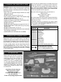
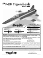
EP
EDF ARF
INSTRUCTION
STRUCTIO
TRUCTION MANUAL
Length:
SPECIFICATIONS
Wingspan:
Wing Area:
22.5 in
[565mm]
Weight:
162 in2
[10.4 dm2]
Wing
Loading:
26.8 oz
[760 g]
23.8 oz/ft2
[73 g /dm2]
37 in [940mm]
Radio:
3-Channel minimum with
two mini servos & mini Rx
Motor,
Motor
ESC
24-45-3790kV
24
45 3790kV Ammo™,
45A ESC
Battery:
2200mAh 14.8V 25C LiPo
WARRANTY
Great Planes ® Model Manufacturing Co. guarantees this kit to
be free from defects in both material and workmanship at the
date of purchase. This warranty does not cover any component
parts damaged by use or modification. In no case shall Great
Planes’ liability exceed the original cost of the purchased kit.
Further, Great Planes reserves the right to change or modify this
warranty without notice.
this kit immediately in new and unused condition to the
place of purchase.
To make a warranty claim send the defective part or item to
Hobby Services at the address below:
Hobby Services
3002 N. Apollo Dr. Suite 1
Champaign IL 61822 USA
In that Great Planes has no control over the final assembly or
material used for final assembly, no liability shall be assumed nor
accepted for any damage resulting from the use by the user of Include a letter stating your name, return shipping address, as
the final user-assembled product. By the act of using the much contact information as possible (daytime telephone
number, fax number, e-mail address), a detailed description of
user-assembled product, the user accepts all resulting liability.
the problem and a photocopy of the purchase receipt. Upon
If the buyer is not prepared to accept the liability associated receipt of the package the problem will be evaluated as quickly
with the use of this product, the buyer is advised to return as possible.
READ THROUGH THIS MANUAL BEFORE STARTING CONSTRUCTION. IT CONTAINS IMPORTANT
INSTRUCTIONS AND WARNINGS CONCERNING THE ASSEMBLY AND USE OF THIS MODEL.
Champaign, Illinois
(217) 398-8970, Ext 5
[email protected]
Entire Contents © Copyright 2010
GPMA1875 Mnl
TABLE OF CONTENTS
AMA
AMA .................................................................................. 2
SAFETY PRECAUTIONS ................................................. 2
LITHIUM BATTERY HANDLING & USAGE ..................... 3
DECISIONS YOU MUST MAKE ........................................ 3
Radio Equipment Recommendations........................... 3
Battery, ESC & Motor Recommendations .................... 3
ADDITIONAL ITEMS REQUIRED .................................... 3
Adhesives & Building Supplies ..................................... 3
Optional Supplies & Tools ............................................ 3
IMPORTANT BUILDING NOTES ...................................... 4
ORDERING REPLACEMENT PARTS .............................. 4
KIT INSPECTION .............................................................. 4
KIT CONTENTS ................................................................ 4
WING INSTALLATION ...................................................... 5
HORIZONTAL TAIL INSTALLATION ................................ 6
EDF FAN PREPARATION & INSTALLATION .................. 7
INSTALL THE RADIO GEAR ............................................ 8
LINK THE CONTROLS ..................................................... 9
HATCH & VERTICAL TAIL INSTALLATION ................... 10
GET THE MODEL READY TO FLY ................................. 11
Check the Control Directions ..................................... 11
Set the Control Throws............................................... 12
Balance the Model ..................................................... 12
PREFLIGHT .................................................................... 13
Identify Your Model ..................................................... 13
Charge the Batteries .................................................. 13
Range Check ............................................................. 13
AMA SAFETY CODE ...................................................... 13
CHECK LIST ................................................................... 14
FLYING ............................................................................ 14
Launching................................................................... 14
Flight .......................................................................... 14
Landing ...................................................................... 14
If you are not already a member of the AMA, please join!
The AMA is the governing body of model aviation and
membership provides liability insurance coverage, protects
modelers’ rights and interests and is required to fly at most
R/C sites.
Academy of Model Aeronautics
5151 East Memorial Drive
Muncie, IN 47302-9252
Tele. (800) 435-9262
Fax (765) 741-0057
Or via the Internet at:
http://www.modelaircraft.org
IMPORTANT!!! Two of the most important things you can do
to preserve the radio controlled aircraft hobby are to avoid
flying near full-scale aircraft and avoid flying near or over
groups of people.
PROTECT YOUR MODEL, YOURSELF
& OTHERS....FOLLOW THESE
IMPORTANT SAFETY PRECAUTIONS
1. Your F-20 EDF ARF should not be considered a toy, but
rather a sophisticated, working model that functions very
much like a full-size airplane. Because of its performance
capabilities, the F-20 EDF ARF, if not assembled and
operated correctly, could possibly cause injury to yourself
or spectators and damage to property.
2. You must assemble the model according to the instructions.
Do not alter or modify the model, as doing so may result in
an unsafe or unflyable model. In a few cases the instructions
may differ slightly from the photos. In those instances the
written instructions should be considered as correct.
3. You must take time to build straight, true and strong.
4. You must use an R/C radio system that is in good condition,
and other components as specified in this instruction
manual. All components must be correctly installed so
that the model operates correctly on the ground and in
the air. You must check the operation of the model and all
components before every flight.
5. If you are not an experienced pilot or have not flown this
type of model before, we recommend that you get the
assistance of an experienced pilot in your R/C club for
your first flights. If you’re not a member of a club, your
local hobby shop has information about clubs in your area
whose membership includes experienced pilots.
The Northrop F-20 Tigershark was a development of the F-5
twin-engine light fighter jet aircraft. The project was initiated
by a demand for exportable fighter jets to supply U.S. allies.
Switching over to a single engine boosted the performance
by 60%, but due to stiff competition and limited interest the
project was cancelled after only 3 prototypes were made.
Great Planes brings you this unique aircraft now in EDF
form. AeroCell™ foam construction provides a lightweight and
durable structure that will handle everyday use. Two AIM-9
Sidewinder missiles and a display stand are included that will
allow your F-20 EDF ARF to look as great sitting on the shelf
as it does in the air. The recommended brushless motor will
allow your F-20 EDF ARF to reach speeds up to 85 mph!
We, as the kit manufacturer, provide you with a top quality,
thoroughly tested kit and instructions, but ultimately the
quality and flyability of your finished model depends
on how you build it; therefore, we cannot in any way
guarantee the performance of your completed model,
and no representations are expressed or implied as to the
performance or safety of your completed model.
For the latest technical updates or manual corrections
to the F-20 EDF ARF visit the Great Planes web site at
www.greatplanes.com. Open the “Airplanes” link, then
select the F-20 EDF ARF. If there is new technical information
or changes to this model a “tech notice” box will appear in
the upper left corner of the page.
Remember: Take your time and follow the instructions to
end up with a well-built model that is straight and true.
2
❏ 1 oz. [30g] Thick Pro CA- (GPMR6014)
❏ Pro Threadlocker thread locking cement (GPMR6060)
❏ Numbered drill bits: #55, #57
❏ Denatured alcohol
DECISIONS YOU MUST MAKE
This is a partial list of items required to finish the F-20 EDF ARF
that may require planning or decision making before starting
to build. Order numbers are provided in parentheses.
Optional Supplies & Tools
Radio Equipment Recommendations
Here is a list of optional tools that will help you build the F-20
EDF ARF.
The F-20 EDF ARF requires a minimum 3-channel radio system
with three micro servos. Ailerons, elevator, and throttle are used
(there is no rudder). A typical 4-channel basic radio system is
adequate for this model. Complete radio systems that include
micro servos and a receiver are available from your local hobby
dealer. In any case, for this airplane you will need:
❏
❏
❏
❏
❏
❏
❏
❏
❏
❏
❏
❏
❏
❏
❏
❏
❏
❏
❏ Futaba® R617FS 2.4GHz Receiver (FUTL7627)
– OR –
❏ Futaba R114F 4-Channel FM Micro Receiver
w/o Crystal (Low Band: FUTL0442; High Band: FUTL0443)
❏ Futaba FM Single conversion receiver crystal for R114F
(Low Band: FUTL62**; High Band: FUTL63**)
❏ (3) Futaba S3114 Micro HT Servos (FUTM0414)
Battery, ESC & Motor Recommendations
The following motor and electronic speed control (ESC) have
been tested extensively and are recommended. With this set
up you can expect to draw 38A of current. If you’re interested
in checking your current, order the optional RC Electronics
Watt’s Up meter listed in the “Optional Supplies & Tools”.
IMPORTANT BUILDING NOTES
❏ Great Planes ElectriFly™ Silver Series SS-45, 45A
• When you see the term test fit in the instructions, it means
that you should first position the part on the assembly
without using any glue, then slightly modify or custom fit
the part as necessary for the best fit.
brushless ESC (GPMM1840)
❏ Great Planes ElectriFly Power Series 2200mAh 14.8V
25C LiPo battery (GPMP0521)
❏ FlightPower EON-X Lite™ 2100mAh 14.8V 25C LiPo
(FPWP4197)
• Whenever the term glue is written you should rely upon
your experience to decide what type of glue to use. When
a specific type of adhesive works best for that step, the
instructions will make a recommendation.
In order to charge your LiPo flight packs, you’ll need a LiPo
charger and cell balancer. We recommend the following ones.
❏ PolyCharge4™ LiPo battery charger (GPMM3015)
❏ Equinox™ 1 to 5 cell LiPo cell balancer (GPMM3160)
❏ Equinox 4S FlightPower adapters (GPMM3182)
❏ 12 Volt DC power supply (HCAP0250)
• Whenever just epoxy is specified you may use either
30-minute (or 45-minute) epoxy or 6-minute epoxy. When
30-minute epoxy is specified it is highly recommended that
you use only 30-minute (or 45-minute) epoxy, because you
will need the working time and/or the additional strength.
• Photos and sketches are placed before the step they
refer to. Frequently you can study photos in following steps
to get another view of the same parts.
ADDITIONAL ITEMS REQUIRED
Adhesives & Building Supplies
This is the list of Adhesives and Building Supplies that are
required to finish the F-20 EDF ARF
❏ Hobby knife (EXLR9018)
❏ #11 Blades (HCAR0311)
❏ Pro™ 30-minute epoxy (GPMR6047)
❏ 1 oz. [30g] Medium Pro CA+ (GPMR6008)
❏ 1 oz. [30g] Medium Foam-Safe CA (GPMR6069)
R/C-56 Glue 4oz (JOZR5007)
Pro 6-minute epoxy (GPMR6045)
Epoxy brushes (6, GPMR8060)
Mixing sticks (50, GPMR8055)
Mixing cups (GPMR8056)
Panel line pen (TOPQ2510)
2 oz. [57g] Spray CA activator (GPMR6035)
CA debonder (GPMR6039)
18" [457mm] Flexible steel rule (HCAR0460)
Hobbico® Builder’s Protractor (HCAR0490)
AccuThrow™ Deflection Gauge (GPMR2405)
Hobby Heat™ micro torch (HCAR0755)
RC Electronics Watt’s Up Watt Meter (RELP0100)
C.G. Machine™ (GPMR2400)
Segmented lead weights 6 oz (GPMQ4485)
1/4" [6.4mm] Heat shrink tubing 9" [228mm] (DUBM2188)
3/8" [9.5mm] Heat shrink tubing 9" [228mm] (DUBM2180)
Red striping tape, 1/8" [3mm] (GPMQ1320)
3
Parts may also be ordered directly from Hobby Services by
calling (217) 398-0007, or via facsimile at (217) 398-7721,
but full retail prices and shipping and handling charges will
apply. Illinois and Nevada residents will also be charged
sales tax. If ordering via fax, include a Visa® or MasterCard®
number and expiration date for payment.
LITHIUM BATTERY HANDLING & USAGE
WARNING!! Read the entire instruction sheet included with
the battery. Failure to follow all instructions could cause
permanent damage to the battery and its surroundings, and
cause bodily harm!
Mail parts orders and payments by personal check to:
• ONLY use a LiPo approved charger. NEVER use a NiCd/
NiMH peak charger!
• NEVER charge in excess of 4.20V per cell.
• ONLY charge through the “charge” lead. NEVER charge
through the “discharge” lead.
• NEVER charge at currents greater than 1C.
• ALWAYS set charger’s output volts to match battery volts.
• ALWAYS charge in a fireproof location.
• NEVER trickle charge.
• NEVER allow battery temperature to exceed 150° F [65° C].
• NEVER disassemble or modify pack wiring in any way or
puncture cells.
• NEVER discharge below 3.0V per cell.
• NEVER place on combustible materials or leave unattended
during charge or discharge.
• ALWAYS KEEP OUT OF REACH OF CHILDREN.
Hobby Services
3002 N. Apollo Drive, Suite 1
Champaign, IL 61822
Be certain to specify the order number exactly as listed in the
Replacement Parts List. Payment by credit card or personal
check only; no C.O.D.
If additional assistance is required for any reason contact
Product Support at [email protected], or
by telephone at (217) 398-8970.
REPLACEMENT PARTS LIST
Order No.
GPMA3230
GPMA3231
GPMA3232
GPMA3233
GPMA3234
GPMA3235
GPMA3236
GPMA3237
GPMA3238
GPMA3239
GPMG3910
GPMG5185
ORDERING REPLACEMENT PARTS
Replacement parts for the Great Planes F-20 EDF are
available using the order numbers in the Replacement Parts
List that follows. The fastest, most economical service can
be provided by your hobby dealer or mail-order company.
To locate a hobby dealer, visit the Great Planes web site
at www.greatplanes.com. Choose “Where to Buy” at the
bottom of the menu on the left side of the page. Follow the
instructions provided on the page to locate a U.S., Canadian
or International dealer.
NOTE
KIT INSPECTION
Before starting to build, take an inventory
of this kit to make sure it is complete and
inspect the parts to make sure they are
of acceptable quality. If any parts are
missing or are not of acceptable quality,
or if you need assistance with assembly,
contact Product Support. When reporting
defective or missing parts, use the part
names exactly as they are written in the
Kit Contents list.
Great Planes Product Support:
3002 N Apollo Drive, Suite 1
Champaign, IL 61822
Telephone: (217) 398-8970, ext. 5
Fax: (217) 398-7721
E-mail: [email protected]
4
Description
Fuselage Set
Wing Set
Tail Surfaces
Canopy/Hatch
Rocket Set
Tail Cone
Decal Sheet
Servo Covers
Display Stand
Fan Hatch/Fin
EDF Fan Unit
Ammo 24-45-3790 Brushless Motor
Full-size plans are not available.
You can download a copy of this
manual at www.greatplanes.com.
WING INSTALLATION
X = X'
X
X'
Mark the center of the carbon wing tube.
❏ 1. Locate the 3 x 460mm carbon wing tube. Make a mark
in the center of the tube by measuring from side to side and
dividing that figure by two. Where distance X equals distance
X', make a small mark on the tube using a felt-tip pen or a
piece of trim tape.
❏ 4. Clean all gluing surfaces with denatured alcohol. Using
thick regular CA, apply a continuous bead of glue into the
spar slot in the bottom of the fuselage. Center the carbon
wing spar using the marks that you made and press it up
into the slot completely. Set the fuselage on a flat table and
make sure that the wing spar is parallel with the table top.
This will ensure that you have inserted the spar correctly. Use
a cotton swab or a paper towel to clean up the excess CA
from the slot. Set the fuselage aside and allow the CA to cure
or spray some CA accelerator on to speed up the cure. Note:
For the remaining steps in this section, please do not use CA
accelerator to cure the CA adhesive until after step 7.
❏ 2. Turn the fuselage over and mark the center of the wing tube
slot. Where distance Y equals distance Y', mark the fuselage.
❏ 3. Test fit the carbon wing tube into the corresponding
slot in the fuselage and test fit each of the wings. Make sure
that your centering marks are correct and correspond with
each other before gluing the wing tube and wings. Make
adjustments as necessary.
❏ 5. Apply thick CA to the wing tabs and the wing root of
each wing where the wing will join with the fuselage. Note:
Wipe the glue across all mating surfaces. Remove excess
glue so that the CA does not run when the wings are joined.
5
HORIZONTAL TAIL INSTALLATION
❏ 1. Test fit the horizontal tail to the bottom of the fuselage.
Slide the stab all the way forward. Note: The elevator joiner
wire must clear the slot in the fuse.
❏ 6. Turn the wings over and apply a bead of CA into the
spar slot in the bottom of each wing. Push the wing tube
into the slot in each wing as you slide the wing firmly up
against the fuselage joint. Fit the wing tabs tightly into the
corresponding fuse pockets.
❏ 7. Insert the 460mm foam filler piece into the wing slot,
being careful to orient the foam so that the stepped portion
faces down and matches the step in the bottom of the
fuselage. Push the foam piece into the slot completely so
that the filler piece lies flush with the bottom surface of the
wing. Clean up any excess CA with a paper towel. Set the
model aside to let the CA cure or spray CA accelerator into
the joint.
❏ 2. Apply thick or medium CA to the center section of the
horizontal tail where it contacts the fuselage.
❏ 3. Fit the horizontal tail to the fuselage, making sure to
slide it all the way forward. Check for proper operation of the
elevator. Spray some CA accelerator into the joint to cure
the CA or turn the fuse over and place a box under the fan
channel to support it as you place weight on the stab center
section. Allow the CA to fully cure.
6
fan in the model so that the ridges on the fan case drop
into the corresponding grooves in the fan duct. Mount the
motor so that the wires exit the motor and face the top of the
model. Allow the glue to fully cure. Note: During installation,
you may notice that the fan rotor’s flange makes contact with
the inner duct cone. This is normal and helps improve fan
efficiency. When you first run the motor on the plane, the
fan will seat itself in the foam. If you feel that the fan is too
tight against the inner duct cone, you may trim the duct cone
using a hobby knife before installation. Trim a little at a time
and check the fit.
EDF FAN PREPARATION & INSTALLATION
This model uses the Great Planes ElectriFly Ammo 24-453790 brushless in-runner motor (GPMG5185, included) and
the Silver Series SS-45 brushless ESC (GPMM1840, not
included)
❏ 1. Use the included EDF fan instruction manual to assemble
and break-in the EDF fan unit. Do not install the rotor cone.
Use threadlocking compound on all screws. Before you glue
the EDF unit into your airplane, we recommend that you
check the fan and motor for proper operation. If there is a
problem it is much easier to take care of before the fan is
glued into the airframe. If you prefer, you can use doublesided tape to hold your fan in place, but you will need to
recess the EDF channel in the fuse to accommodate the
thickness of the foam tape.
❏ 3. Cut the 2" [51mm] piece of hook and loop fastener
material in half so that you have equal amounts of material
to fasten your ESC and receiver in place. Stick one piece on
the back side of your ESC. Turn the model over and route the
ESC motor leads through the upper channel inside the fuse
and out into the motor bay.
❏ 4. Connect the supplied motor lead extensions to the
motor wires. Refer to the instructions that came with your
ESC to correctly arm and operate the motor. Check the
direction of motor operation and that air is blowing out of the
back side of the EDF unit. If the fan is rotating backwards,
swap the position of any two motor leads and test the fan
rotation again. Use 1/4" [6.4mm] diameter heat shrink tubing
(not supplied) to secure each connection. If heat shrink
tubing is not available, you may wrap the connectors with
electrical tape.
❏ 2. Apply 30-minute epoxy or CA to the fan duct in the
recessed area where the EDF fan unit mounts. Mount the
7
INSTALL THE RADIO GEAR
With servos centered, position
each arm 90° to the servo case.
LEFT
Aileron Servo
RIGHT
Aileron Servo
Elevator
Servo
❏ 4. Identify the left and right aileron servos and tie each
servo lead guide string to its corresponding servo lead. Pull
each servo lead through the fuselage and glue each servo
in position.
❏ 1. Use your radio to center each of your servos. Remove
the servo arms and reposition each one so that the servo arm
is 90° to the servo case. Prepare two aileron servos and one
elevator servo as shown in the sketch. Clip off the unused
servo arms. Reinstall the servo arm screw on each servo.
❏ 5. Remove the guide strings from the aileron servo wires.
Attach the supplied Y-harness to the two aileron servo leads
and the 14” [365mm] extension to the elevator servo lead using
electrical tape or 3/8” [9.5mm] diameter heat shrink tubing to
secure the connections. Tie the guide string to the aileron
Y-harness and the elevator extension lead and route the wires
into the radio compartment. Note: You should be careful to
match the polarity of the servo leads with the lead extensions.
❏ 2. Using a #57 [1.09mm] drill bit, enlarge the hole that is
5/16" [7.9mm] from the output shaft on each servo arm. If
you don’t have a #57 drill bit, carefully use a hobby knife to
enlarge the hole until you can fit the 1mm Z-bend pushrods.
❏ 3. Route the elevator servo lead through the slot in the
bottom of the fuselage. Make sure that the servo’s output
shaft faces forward and the servo arm faces up toward the
top of the model. Clean the servo with denatured alcohol,
then glue into position as shown using thick or medium CA.
❏ 6. Pull the servo leads through the upper channel so that
they are positioned as shown. Route the elevator lead so that
8
the connector tucks into the upper channel. Tuck the aileron
connectors into the side channels and route the leads up
along the notched groove. Place a small drop of CA onto
the wires to hold them to the notched groove. Note: If you
are using a 72MHz radio system, route the included antenna
tube through the upper channel at this time.
LINK THE CONTROLS
❏ 1. Use your radio system to verify that the servos are
centered. The aileron servos should be parallel with each
other. Use your radio’s sub-trim function to correct this.
Caution: Do not arm the motor by moving the throttle. Debris
can be ingested and thrown causing damage or injury. If you
do accidentally arm the motor, unplug the battery, set the
throttle to cutoff, and re-apply power to reset the ESC.
❏ 7. Stick a 1" [25mm] piece of hook and loop fastener material
to the back side of your receiver. Plug the servo leads and the
ESC signal lead into their respective channel in the receiver.
❏ 2. Remove the locking screw from the screw lock pushrod
❏ 8. Peel the backing paper off of the hook and loop material connectors
on the elevator and both ailerons.
and stick your ESC and receiver inside the fuselage in the
locations shown. You can stick the ESC to the left or the right
side depending on the location of your battery’s wires.
❏ 3. Install the 1 x 130mm wire pushrod onto the elevator
servo so that the Z-bend is in the hole you drilled on the servo
9
arm. Deflect the elevator down and fit the pushrod into the
screw-lock pushrod connector. Apply a drop of thread locking
compound to the screw threads and install the locking screw.
With the elevator at neutral and the elevator servo centered,
tighten the locking screw. Note: If you have a difficult time
trying to insert the pushrod while deflecting the controls, trim
off 1/8" [3.2mm] of the pushrod end and try again.
HATCH & VERTICAL TAIL INSTALLATION
❏ 1. Apply a bead of medium regular CA adhesive to the
motor hatch at the base of where the vertical fin will mount.
Fit the fin to the motor hatch.
❏ 4. Install the 1 x 60mm wire pushrods onto each aileron
servo so that the Z-bend is in the hole you drilled on the
servo arm. Deflect each aileron up and fit the pushrod into
the screw-lock pushrod connector. Apply a drop of thread
locking compound to the screw threads and install the
locking screw. Set each aileron at neutral throw and tighten
the locking screw.
❏ 2. Test fit the motor hatch to the fuselage. Once the tabs
are in the slots, push the hatch down and slide it forward until
the magnets engage.
If you are installing a 2.4GHz radio system, please install
the hatch and skip to step 4.
❏ ❏ 5. Peel the backing paper from the double-sided tape
applied to the left and right aileron servo covers. Install the
servo covers as shown.
❏ 3. If you are using a 72MHz radio system, slide the antenna
and antenna tube into the upper channel in the hatch as you
install the hatch.
10
display stand is not made of AeroCell™ foam. Only foam-safe
CA adhesive can be used. Regular CA will melt the foam.
❏ 4. Install the tail cone. Use cellophane tape (household
tape) to secure it to the hatch and the fuselage. If you choose
to use glue, R/C-56 Glue (JOZR5007) will allow easy removal
of the hatch in the future. Medium CA is also acceptable, but
only if two small drops are used 180° apart from each other.
❏ 3. Assemble the stand by first interlocking the supports
and then adding the two vertical side braces. Add the top
and bottom lateral braces next. The top braces are smaller
to allow the aileron servos and linkages to clear.
GET THE MODEL READY TO FLY
❏ 4. Apply the pre-cut decals, using the box photos as a
guide for placement
Check the Control Directions
❏ 1. Turn on the transmitter and receiver and center the
trims. If necessary, remove the servo arms from the servos
and reposition them so they are centered. Reinstall the
screws that hold on the servo arms.
❏ 2. With the transmitter and receiver still on, check all the
control surfaces to see if they are centered. If necessary,
adjust the screw-lock pushrod connectors to center the
control surfaces.
3-CHANNEL
RADIO SET UP
❏ 1. Stick the hook side of the 4" [102mm] piece of hook and
loop material to the battery tray in the location shown.
(STANDARD MODE 2)
FULL
THROTTLE
RIGHT AILERON
MOVES UP
LEFT AILERON
MOVES DOWN
ELEVATOR
MOVES DOWN
❏ 3. Make certain that the control surfaces and the ESC
respond in the correct direction as shown in the diagram.
If any of the controls respond in the wrong direction, use
the servo reversing in the transmitter to reverse the servos
connected to those controls. Be certain the control surfaces
have remained centered. Adjust if necessary.
❏ 2. Locate the parts to assemble the foam display stand. There
should be two side braces, two top braces (small), two bottom
braces (large), and two interlocking supports. Note: The foam
11
Set the Control Throws
Balance the Model (C.G.)
At this stage the model should be in ready-to-fly condition.
Place the battery in the battery tray but do not connect it.
❏ 1. The C.G. is located 3-3/4" [95mm] back from the
LE of the wing at the fuselage (the seam where the wing
panels have been joined to the fuselage). Make a small mark
at this location on the top side of the wing using a felt-tipped
pen or a piece of trim tape. Please fly the model at this C.G
for the first few flights. After this, you may move the C.G.
forward up to 1/8" [3.2mm] or aft up to 1/16" [1.6mm].
❏ 1. Use a ruler, protractor, Great Planes AccuThrow™, or
inclinometer to accurately measure and set the control throw
of each control surface as indicated in the chart that follows.
If your radio does not have dual rates, we recommend setting
the throws at the low rate setting.
Note: The throws are measured at the widest part (root) of
the elevators and ailerons.
❏ 2. Depending on your radio, you may have to adjust
the mechanical position of the pushrod linkages in order
to achieve the proper throw. This is preferred to adjusting
AFR, ATV, or servo end-points in the transmitter because it
preserves the control resolution of the servo and allows for
better control of the model.
❏ 2. With all parts of the model installed (ready to fly), place
the model upside-down on a Great Planes C.G. Machine, or
lift it upside-down at the balance point you marked.
❏ 3. If the tail drops, the model is “tail heavy” and the battery
pack must be shifted forward to balance. If the nose drops, the
model is “nose heavy” and the battery pack must be shifted
back to balance. If you still cannot achieve the recommended
C.G., you may add segmented lead weight to the nose or tail
(GPMQ4485). The C.G. range of this airplane is from 3-5/8"
[92mm] to 3-13/16" [97mm] as measured from the LE of the
wing at the root.
❏ 3. Tighten all screw-lock pushrod connectors and install
all servo arm mounting screws.
These are the recommended control surface throws:
HIGH RATE
ELEVATOR
AILERONS
LOW RATE
Up
Down
Up
Down
3/8"
[10mm]
14˚
3/8"
[10mm]
14˚
1/4"
[7mm]
10˚
1/4"
[7mm]
10˚
Up
Down
Up
Down
3/8"
[10mm]
11˚
3/8"
[10mm]
11˚
1/4"
[7mm]
7.5˚
1/4"
[7mm]
7.5˚
Note: Use high rate elevator for takeoffs and landings.
12
LITHIUM BATTERY HANDLING & USAGE
PREFLIGHT
WARNING!! Read the entire instruction sheet included with
your battery. Failure to follow all instructions could cause
permanent damage to the battery and its surroundings, and
cause bodily harm!
Identify Your Model
No matter if you fly at an AMA sanctioned R/C club site or
if you fly somewhere on your own, you should always have
your name, address, telephone number and AMA number
on or inside your model. It is required at all AMA R/C club
flying sites and AMA sanctioned flying events. Fill out the
identification tag on the back cover of this manual and place it
on or inside your model.
• ONLY use a LiPo approved charger. NEVER use a
NiCd/NiMH peak charger.
• NEVER charge in excess of 4.20V per cell.
• ONLY charge through the “charge” lead. NEVER
charge through the “discharge” lead.
• NEVER charge at currents greater than 1C.
• ALWAYS set the charger’s output volts to match
the battery volts.
Charge the Batteries
• ALWAYS charge in a fireproof location.
Follow the battery charging instructions that came with your
radio control system to charge the transmitter battery. You
should always charge your transmitter battery the night
before you go flying, and at other times as recommended by
the radio manufacturer. Charge your airplane’s LiPo battery
according to the battery manufacturer’s recommendations
and always charge it before you fly.
• NEVER trickle charge.
• NEVER allow the battery temperature to exceed
150° F (65° C).
• NEVER disassemble or modify the pack wiring in
any way or puncture the cells.
• NEVER discharge below 2.5V per cell.
• NEVER place the battery or charger on
combustible materials or leave it unattended during
charge or discharge.
CAUTION: Unless the instructions that came with your
radio system state differently, the initial charge on new
transmitter batteries should be done for 15 hours using
the slow-charger that came with the radio system.
This will “condition” the battery so that the next charge
may be done using the fast-charger of your choice. If the
initial charge is done with a fast-charger the batteries may
not reach their full capacity and you may be flying with
batteries that are only partially charged.
• ALWAYS KEEP OUT OF THE REACH OF
CHILDREN.
• NEVER charge the battery in the plane.
• ALWAYS remove the battery from the plane after
a crash. Set it aside in a safe location for at least
20 minutes. If the battery is damaged in the crash it
could catch fire.
If the battery starts to swell, quickly move the battery to a safe
location, preferably outside: Place it in a bucket, covering the
battery with sand.
Range Check
Ground check the operational range of your radio before the
first flight of the day. With the transmitter antenna collapsed
and the receiver and transmitter on, you should be able
to walk at least 100 feet [30m] away from the model and
still have control. Have an assistant stand by your model
and, while you work the controls, tell you what the control
surfaces are doing. Repeat this test with the motor running
at various speeds with an assistant holding the model, using
hand signals to show you what is happening. If the control
surfaces do not respond correctly, do not fly! Find and
correct the problem first. Look for loose servo connections
or broken wires, corroded wires on old servo connectors,
poor solder joints in your battery pack or a defective cell, or a
damaged receiver crystal from a previous crash.
13
AMA SAFETY CODE (EXCERPTS)
CHECK LIST
Read and abide by the following excerpts from the Academy
of Model Aeronautics Safety Code. For the complete Safety
Code refer to Model Aviation magazine, the AMA web site or
the Code that came with your AMA license.
During the last few moments of preparation your mind may
be elsewhere anticipating the excitement of the first flight.
Because of this, you may be more likely to overlook certain
checks and procedures that should be performed before the
model is flown. To help avoid this, a check list is provided to
make sure these important areas are not overlooked. Many
are covered in the instruction manual, so where appropriate
refer to the manual for complete instructions. Be sure to
check the items off as they are completed.
General
1) I will not fly my model aircraft in sanctioned events, air shows,
or model flying demonstrations until it has been proven to be
airworthy by having been previously, successfully flight tested.
❏ 1.
❏ 2.
2) I will not fly my model aircraft higher than approximately
400 feet within 3 miles of an airport without notifying the
airport operator. I will give right-of-way and avoid flying in the
proximity of full-scale aircraft. Where necessary, an observer
shall be utilized to supervise flying to avoid having models fly
in the proximity of full-scale aircraft.
❏ 3.
❏ 4.
❏ 5.
3) Where established, I will abide by the safety rules for the
flying site I use, and I will not willfully and deliberately fly my
models in a careless, reckless and/or dangerous manner.
5) I will not fly my model unless it is identified with my name
and address or AMA number, on or in the model. Note: This
does not apply to models while being flown indoors.
❏ 6.
❏ 7.
❏ 8.
❏ 9.
7) I will not operate models with pyrotechnics (any device
that explodes, burns, or propels a projectile of any kind).
Check the C.G. according to the measurements
provided in the manual.
Be certain the battery and receiver are securely
mounted in the fuselage.
Confirm that all controls operate in the correct direction
and the throws are set up according to the manual.
Inspect the ducted fan unit for obvious damage and
tighten the fan screw.
Check the operation of the ducted fan unit prior to
each flight.
Make sure that all servo arms are secured to the
servos with the screws included with your radio.
Place your name, address, AMA number and telephone
number on or inside your model.
If you wish to photograph your model, do so before
your first flight.
Range check your radio when you get to the flying field.
Radio Control
FLYING
1) I will have completed a successful radio equipment ground
check before the first flight of a new or repaired model.
IMPORTANT: If you are an inexperienced modeler we
strongly urge you to seek the assistance of a competent,
experienced R/C pilot to check your model for airworthiness
AND to teach you how to fly. Attempting to learn to fly on your
own is dangerous and may result in destruction of your model
or even injury to yourself and others. You should fly under
the careful watch of an instructor until you have acquired
the skills necessary for safe and fully controlled operation of
your model.
2) I will not fly my model aircraft in the presence of spectators
until I become a qualified flier, unless assisted by an
experienced helper.
3) At all flying sites a straight or curved line(s) must be
established in front of which all flying takes place with the
other side for spectators. Only personnel involved with flying
the aircraft are allowed at or in the front of the flight line.
Intentional flying behind the flight line is prohibited.
Launching
4) I will operate my model using only radio control frequencies
currently allowed by the Federal Communications Commission.
Less-experienced flyers should fly the F-20 EDF ARF only
in calm (less than five miles per hour) conditions. Frequently,
winds are calm in the early morning and early evening. Often
these are the most enjoyable times to fly anyway!
5) I will not knowingly operate my model within three
miles of any pre-existing flying site except in accordance
with the frequency sharing agreement listed (in the
complete AMA Safety Code).
We suggest always using a skilled assistant to help you
launch the airplane. Use HIGH rates for takeoff and let the
model build up speed before attempting to climb out.
9) Under no circumstances may a pilot or other person
touch a powered model in flight; nor should any part of the
model other than the landing gear intentionally touch
the ground, except while landing.
Turn on the transmitter and plug the battery into the ESC. Turn
on the receiver by following the instructions that came with your
ESC. Secure the canopy hatch in place.
14
Adjust the elevator trim so the model flies level at the throttle
setting you are using. Adjust the aileron trim to level the wings.
It may take a few minutes to get the trims adjusted, but this
should be your first priority once at a comfortable altitude.
Continue to fly around, executing turns and making mental
notes (or having your assistant take notes for you) of what
additional adjustments or C.G. changes may be required to
fine tune the model so it flies the way you like. Try some
slow flight and standard stalls to familiarize yourself with the
airplane’s slow-speed handling characteristics. When you
are comfortable, try making a few practice approaches.
IMPORTANT: Confirm that the transmitter operates the
controls properly by moving the sticks and watching the
surfaces respond.
When you’re ready to launch, have your assistant hold
the F-20 EDF ARF behind the C.G above the wing for
an underhanded toss or behind the TE of the wing for an
overhanded toss. Practice the throwing motion and choose
the method that best suits the person launching the model.
Line up the model so that the nose is pointed directly into the
wind. Advance the power to full and have your assistant toss
the model into the air with a slightly nose-up attitude. Be
ready on the controls to make the corrections necessary to
build up speed while maintaining a wings-level attitude.
Landing
To minimize wear and the possibility of damage, choose
a grass runway that is flat and free of deep ruts. Bring the
power back to about 1/2 stick of throttle and turn downwind
(keeping your current traffic pattern in mind). Maintain your
speed and altitude during your downwind leg and turn to
base. Start a descent and throttle back a few clicks. Keep
power in when you turn to final. When you’re about 6 meters
[20 feet] from the end of the runway, cut the power and drop
the nose slightly to maintain speed. Flare gently for landing.
When the model has gained adequate flying speed under its
own power, gently pull the elevator stick back until the airplane
starts a gradual climb. If you notice the model losing speed,
release the elevator stick and allow the model to gain airspeed
before climbing out. Continue a gradual climb and establish a
gentle turn (away from yourself and others) until the airplane
reaches an altitude of 20 to 30 meters [75 to 100 feet].
Flight
Until you are able to accurately judge how far the F-20 EDF
ARF can glide, it may be helpful to reserve some battery
power to run the motor so the plane can be flown back to
the runway.
The main purpose of the first few flights is to learn how the
model behaves and to adjust the trims for level flight. After
the model has climbed to a safe altitude, reduce the throttle
slightly to slow the model, yet maintain altitude. The F-20
EDF ARF should fly well at about 1/2 throttle.
GOOD LUCK AND GREAT FLYING!
This model belongs to:
Name
Address
City
State
ZIP
Phone #
AMA #
Make a copy of this identification tag
and put it on or inside your model.
15
ALSO AVAILABLE FROM GREAT PLANES
ElectriFly™ VFO ARF
Almost Ready-to-Fly
Electric Sport/3D Aerobat
GPMA1135
Part plane, part helicopter — all fun!
Wingspan: 26.5 in (675 mm)
Wing Area: 382 in² (24.6 dm²)
Weight: 9-10 oz (255-285 g)
Wing Loading: 3.4-3.8 oz/ft² (10-12 g/dm²)
Length: 29.5 in (750 mm)
Requires:
• 6-channel radio w/4 micro servos & elevon mixing (min.)
• 300-size outrunner brushless motor
• 12A brushless ESC (min.)
• 11.1V 300mAh LiPo battery & LiPo charger
The VFO (Vertical Flying Object) takes off like a rocket, hovers like a heli and flies like a plane — and does it all with
economical on-board components. It performs Harriers, high-alpha and prop hangs with ease, and transitions from a Wall
directly into a tumbling back flip. Lightweight, finished foam parts with servo cut-outs and easy-to-use pushrods make
assembly quick and easy. Carbon-fiber bracing offers lightweight support...and oversized control surfaces deliver massive
maneuvering power.
Blistering EDF performance!
ElectriFly Evader™ ARF
Almost Ready-to-Fly
Electric Ducted Fan Jet
GPMA1800
Wingspan: 26.5 in (675 mm)
Wing Area: 153 in² (9.9 dm²)
Weight: 28-30 oz (790-850 g)
Wing Loading: 26.4-28.2 oz/ft²
(81-86 g/dm²)
Length: 30.5 in (775 mm)
Requires:
• 4-channel radio w/two 20 oz-in torque mini servos
and mini receiver
• 35A brushless ESC
• 14.8V 2200mAh LiPo battery & LiPo charger
Satisfy the urge for jet looks and speed — economically, in a convenient size, and with “goes where you point it” stability
plus the potential for thrilling sport aerobatics. Constructed of a fiberglass fuselage and MonoKote® film-covered, built-up
wing and tail surfaces, the lightweight Evader reaches straight-and-level flight speeds of 100+ mph*. Its impressive thrust
comes from an included HyperFlow™ ducted fan unit with Ammo™ 24-45-3790 motor. ElectriFly also includes a 15-foot
bungee for easy launching and decals for military and sport trim schemes.
* At sea level with recommended electronics.