1
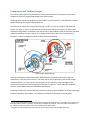
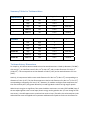
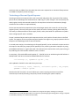
Summary Tables for Turbomachines COMPRESSORS Flow Rate Vaned Diffuser? Matching Turbine Usage Compressor #1 Low Yes 1 or 2 Compressor #2 High Yes 3 or 4 Compressor #3 High No 3 or 4 alternate Compressor #4 Medium Yes 5 or 6 Compressor #5 Medium No 5 or 6 baseline TURBINES Flow Rate Inlet Temp. Matching Compressor Usage Turbine #1 Low High 1 Turbine #2 Low Low 1 Turbine #3 High High 2 or 3 Turbine #4 High Low 2 or 3 alternate Turbine #5 Medium High 4 or 5 Turbine #6 Medium Low 4 or 5 baseline Turbomachinery Dimensions For simplicity, all turbines were assumed to have the same dimensions: a blade tip diameter (“DTURB”) of 9.4cm (3.7”), an inlet flow area of 1.85e‐3 m2 (1.99e‐2 ft2), and an outlet flow area of 2.13e‐3 m2 (2.29e‐2 ft2). This corresponds to an inlet diameter of 4.9cm (1.91”) and an outlet diameter of 5.2cm (2.05”). Similarly, all compressors had the same outlet flow area of 1.36e‐3 m2 (1.46e‐2 ft2), corresponding to a diameter of 4.2cm (1.64”). The low‐flow compressors had an inlet flow area of 1.46e‐3 m2 (1.57e‐2 ft2), corresponding to a diameter of 4.3cm (1.70”). However, for medium and higher flow compressors the inlet was raised by 30% (14% greater diameter) to avoid high Mach numbers at high engine speeds. When kinetic energies are significant, flow areas should be continuous: at a static (STAT=NORM) lump, if the two adjoining flow areas are not equal, kinetic energy can be gained or lost. (If a real change in flow area occurs, it should happen across a path and not across a lump.) Therefore, the turbomachinery inlet and outlet flow areas are applied to the upstream and downstream paths to make sure that flow area