1
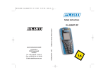
Instruction Manual
Ex-PMR 500
Contents
1.
2.
3.
4.
5.
6.
7.
8.
8.1
8.2
8.3
8.4
8.5.
8.6.
8.7.
8.8.
9.
10.
11.
12.
13.
Use
Safety Advice
Error and Excessive Load
Safety Regulations
Precautionary Advice
Ex-Data
Technical Data
Operating Instructions
Indicating and operating elements, connections
Functions
Power Supply
Accumulator charging
Accumulator change
Accumulator Care
Safety Advice
Integrated Aerial
Operating elements and connections
Connections and regulator on the top
Operating elements on the left and right sides
Buttons on the front
Indicator/Display
Operation
Switching radio equipment on and off
Adjusting Volume
Tuning and memory operation
Low noise barrier/squelch
Search
Light Display
Button locking device
Surveillance function
Acoustic signaling
Clone function
Pilot process DCS and CTCSS
Automatic transmission time boundaries
Transmission time delay
RESET
Legality and technology
Repair
Cleaning
Guarantee and Liability
EG Conformity of declaration
EG Certificate of conformity
page
2
2
2
2-3
3
3
3
4
4-5
6-7
7
7-8
8
8
8
9
9
9
10
10 - 13
14 - 15
16
16
16
16 - 17
17 - 18
18 - 19
19
19
20 - 22
22
22 - 23
23 - 26
27
27 - 28
28
28 - 29
29
29
30
31
31 - 33
1. Use
The Ex-PMR 500 is, in many European countries, a registration free piece of radio
equipment in the range of 446-Mhz for use in hazardous areas (apart from fire
damp holes) according to zones 2 and 1 according to IEC/CENELEC.
2. Safety Advice
The following safety regulations contain information and precautionary advice,
which must comply with the described conditions to guarantee a safe operation.
Before use it is imperative to read these safety regulations and operating
instructions! In case of doubt (due to translation and/or printing errors)
reference should be made to the original German instruction manual.
3. Error and Excessive Load
In order to avoid interference with the safety of the equipment, the equipment must
be taken out of operation and removed immediately from the hazardous area. The
unintentional putting back into operation must be prevented. We recommend that
the equipment should be returned to the manufacturer for testing.
The safety of the equipment can become damaged if;
- Damages are visible on the casing
- Equipment is exposed to improper loads
- Equipment is stored improperly
- Equipment has suffered damage whilst in transit
- Equipment labeling is illegible
- Functioning errors occur
- The authorized boundaries are exceeded (see7. and 13.)
4. Safety Regulations
When using the equipment the user is required to follow the usual safety advice to
prevent any operating errors on the equipment.
- The equipment must not be opened within the hazardous area
- The accumulator pack must only be changed outside of the hazardous area
- When connecting the accu pack, the user must pay attention to a safe engaging
of the six point plug.
- The carrying of additional accus in the hazardous area is not permitted.
- The accu pack may only be charged with the accompanying charging device
Lt-500* outside the hazardous area.
- Only those accus belonging to the work AM500 can be used.
- The use of deviant accus is strictly forbidden. They lead to the removal of the
protection and present a safety risk.
- The equipment may only be used in the hazardous area with the accompanying
leather case.
2
Pay attention when using the equipment that the leather case is always
completely fastened.
- Only ECOM`s permitted equipment may be used.
5. Precautionary Advice
Electromagnetic waves can cause disturbance and can damage your health!
Since no defined statements can be made with reference to the interfering
immunity of the pacemakers, we recommend that pacemaker carriers refrain
from general contact with the radio transceiver.
Transmission should not take place in the vicinity of people with pacemakers!
6. Ex-Data
EG Certificate of Conformity no.:
EG Marking:
TÜV01 ATEX 1713X
II 2 G EEx ia IIC T4
Authorised for zone 1 equipment group II, gas group C hazardous gasses, humidity
or mist, temperature class T4.
7. Technical Data
Surrounding temperature Ta:
Storage temperature:
-20…+50 deg C
-20…+60 deg C (without ex-accu pack)
Power supply:
Running duration:
Dimensions:
Weight:
IP Protective level:
Ex Accupack "AM500”
7-12 hours (90% standby, 5% TX, 5% RX)
58 x 145 x 27 mm (B x H x T)
about 410g (with accupack)
IP22
Frequency range:
Reception switch:
446,00625 – 446,09375 MHz
super double with 1.ZF 21,4 MHz and 2. ZF 455 kHz
Sensitivity:
about 0,20 µV for 12 dB SINAD
Tuning framework:
Transmission power:
Secondary wavelength/harmonic:
NF – Initial performance:
12,5 kHz
500 mW EIRP
better than – 60 dB
max. 0,5 W on 16 Ohm
CE Marking:
Radio admisson:
0102
ICT D801 459L
3
8. Operating Instructions
Please read thoroughly through these operating instructions to enable you to get
to know all functions of your Ex-PMR 500 and to enable you to use it. For your
own information and safety read the advice on the following pages!
8.1 Indicator and operating elements, connections
4
Front
1. MO/Fr/Ch: squelch bridge, changeover frequency/channel indicator, changeover:
CTCSS-frequency or DCS code
2. DOWN/TS: Channel and functions, turn downwards, adjust CTCSS sound or
DCS code.
3. UP/TO: turn the channel and functions upwards, activate the CTCSS operation
ON/OFF, CTCSS or DCS code
4. Lighting ON/OFF, reception tone ON/OFF, CTCSS or DCS code reception receipt
ON/OFF
5. MR/MW: memory, storage
6. SC/DW: search ON/OFF, two channel surveillance ON/OFF
7. PS/LOCK: battery-economy switch, button locking device
8. Microphone
9. Loudspeaker
10. Accu area
Top
1. VOL/OFF: high volume regulator, switch ON/OFF
2. SQ: low noise barrier-regulator/squelch
3. Aerial
4. MIC/SPK: connection for external microphone and external loudspeaker:
protective cover
Safety Advice:
Here, only connect equipment released by ECOM!
Left side, reverse, right side
1. transmission button PTT: transmission and reception switch
2. FUNC: secondary function activated by buttons
5
8.2. Functions
All 8 channels are very easily changeable.
The Ex-PMR 500 can operate on all 8 channels.
10 storage spaces
So that you always have sufficient regular alternatives for your radio partner.
Search finds active channels
The automatic search (scanner) searches and finds occupied channels where it then
stops.
CTCSS and DCS pilot system
For accurate callings of partner systems, two pilot systems are eligible. In the
CTCSS procedure there are 47 tones or numbers available, in the DCS process,
there are 83 three part numbers.
Acoustic signaling
On request the reception of a suitable pilot can be acoustically (alarm sound)
announced.
Surveillance function
This procedure offers the opportunity to observe people. The Ex PMR 500 reacts to
sound.
Emergency calling mode
To activate the surveillance function, an emergency signal is sent out by pressing the
button PS.
6 varied calling sounds
By pressing the transmission button at the same time as another button, 6 varied calling tones are sent out.
Clone function
With the help of the clone function all of the altered adjustments can be transferred
from an ExPMR 500 (master) to another EX PMR 500 (slave) by the user.
Tone scan mode
This function allows the investigation of received signals depending on which tone
squelch – frequency they contain. This method only operates in CTCSS operations.
Maximal transmission power
The transmission power is 1 Watt and completely exhausts the 500 Watt radiation
licence settings on the integrated aerial.
As a result – according to the surroundings- radio contacts are possible over more
kilometers.
Storage of recent adjustments/alterations
The last channel adjustments can be stored by switching off
(with a charged FM for crystal clear connections
The transmission occurs in frequency modulations (FM) which with UKW radio, guarantees a lifelike and slighter interference reproduction.
6
FM for crystal clear connections
The transmission occurs in frequency modulations (FM) which with UKW radio,
guarantees a lifelike and slighter interference reproduction.
Monitor – function for weak signals
To receive much weaker signals the low noise barrier must bridge the gap.
Lighting Display
All functions of the EX-PMR 500 can be read on the display – eg, the adjusted radiochannel. The display can be lit up by pressing a button for a better reading when it is
half-light or dark.
Button locking device to avoid errors
The buttons lock themselves electronically. Inadvertent errors will be avoided – like,
e.g. an unintentional change of channel, when the radio equipment is secured by a
belt, and ready for operation.
Double channel surveillance "Dual watch”
Thanks to the double channel surveillance, one can hear from one channel whilst a
different channel is being observed automatically – as a result no call can be missed!
Economical dealings with the accus
An accu saving switch (PS) like an eligible automatic switching off, ensures that the
accus are maintained longer. If it is time therefore, for an accu charging or a change
of accu, it would be signaled on the display.
Sockets for loud speakers and microphone
Apart from the installed loudspeaker and microphone, the sockets allow a combination
of an external loudspeaker and an external microphone or an ear piece/microphone
connection on the top.
Warning, only that of ECOM`s released equipment may be plugged in!
8.3. Power Supply
Before using the ExPMR 500, the accumulator pack must be charged. If the accu pack
is almost completely discharged, the accu symbol will flash. The accu must then be
charged.
Accu charging
- Switch the device off during charging
- The accu may only be charged with the charging device Lt-500Ex* outside the
- hazardous area.
7
- In addition place the radio equipment Ex-PMR 500 in the charging case.
- The red LED on the device indicates that the accu is being charged.
- For conservational charging, the green LED shines.
Advice: The charging socket is deactivated on the side of the equipment.
Accu change
Only the Ex accumulator module Type AM 500 may be used.
- Remove the equipment from the hazardous area
- Open the leather case and remove the Ex PMR 500
- Push the lock LOCK to the front of the device
- Place your thumb on the lid of the accu pack and press and remove downwards.
- Remove the pack from the accu area and carefully remove the plug.
- Warning: Do not pull on the cable!
- Insert a substitute accu and connect.
- Pay attention to a safe engagement of the six pin plug!
- Seal the accu area with a lid, afterwards, the accu area must be secured with
- the lock bolt LOCK.
- Secure the Ex PMR 500 in a leather case and seal completely.
- Warning: Do not carry the substitute accu in the hazardous area!
Accu care
- Before use, the accu should be charged completely.
- Ensure that the maximal capacity of the accu is reached according to approximately
- 6 charging and discharging cycles.
- Since the efficiency of the accu decreases in the course of time, one should
- occasionally discharge it completely so that the full capacity can be maintained.
- In addition the equipment can be left on until it turns itself off. The accu "AM500” must
- be completely charged outside of the hazardous area.
Safety advice
- Do not drop the accu pack, do not damage, do not dismantle and do not
- expose to unauthorized temperatures (-20 to +50 deg C)!
- Only charge the pack as described in the operating instructions!
- Never leave a discharged pack for a long time in unused equipment!
- Do not store the pack for longer than 6 months without discharging and
- recharging in the meantime!
- Under no circumstances must one throw the accu into an open fire or into
- domestic rubbish!
8
8.4. Integrated aerial
The Ex PMR 500 is delivered with a flexible integrated rubber spiral aerial and must
only be used with this aerial!
This integrated aerial is insoluble via a SMA socket, when connected with the radio
telephone device.
Advice:
- Never send without the integrated aerial!
- The final transmission stage of your radio equipment could become
- damaged on other ways!
- Never place the radio equipment on the aerial!
- The connection of another aerial is a punishable offence!
8.5 Operating elements and connections
In this section the meaning of the single connections and buttons will be explained in
great detail. Please take the positions described on page 4.
Connections and regulator on the top
➀ VOL/OFF
With the inner part of the double regulator, switch the radio equipment on or off and
adjust the volume. The radio equipment is switched off if this regulator is on the left
side. To switch on turn to the right (click).
Turn the regulator clockwise in order to raise the volume.
Warning: Do not turn the loudspeaker on too high, especially for operations using
headphones!! Ear damage could be consequential!
➁ SQ
Regulator for low noise barrier. This has no function for pilot procedures CTCSS. On
the left side the low noise barrier is switched off.If you turn the regulator clockwise then
the level recorder of the low noise barrier is raised. The low noise barrier should be
installed so that no murmurs sound from the loudspeaker.
➂ 3. Integrated aerial/aerial connections
The integrated aerial is connected to this SMA socket.
➃ 4. Sockets MIC and SPK
Under the protective cap the connections for an external microphone MIC and an
external loudspeaker SPK can be found. If this is used e.g. as equipment containing
speech, the internal microphone or the internal loudspeaker will be switched off. If the
sockets are not used, cover them with protective caps so that neither spray water nor
dust can enter.
Warning: One may only use equipment that has been released for operation for the
ExPMR 500 by ECOM.
9
Operating elements on the left and right as well as the back
➀ 1. Transmission and receiving change over, PTT Button
If you press the PTT button, it should change from reception to transmission. Let
go of the PTT button in order to change it back to reception.
Advice; The abbreviation PTT stands for "push to talk”.
➁ 2. FUNC button functioning
Some buttons have two functions. Their second function is available as long as
though the FUNC button is pressed – indicator F, top left on the display.
Buttons on the front
➀ MO/Fr/Ch
This button has many functions:
- By directly pressing this button, the low noise barrier can be bridged as long as
though the button MO is then released.
- If the button is pressed for longer than one second, statistical information will be
received one after the other for the different pilots as well as the search
jump-function.
After work the indicator receives rc off and tc off for switched off CTCSS
operations as well as SCSP off, because no channel is marked to jump.
For a switched on operation and activated sound squelch, rc and tc will be
indicated as well as the switched on CTCSS sound. If a channel is marked
to jump, then indicator on01 will follow from SCSP (for channel one in this case).
Afterwards the frequency can be read from the display.
- For the second function, the frequency and channel indicator can be changed on
the large display. Hold the FUNC button (indicator F) and simultaneously press
the MO/Fr/Ch button.
➁ (DOWN) / TS
This button has two functions;
- By pressing this button , the channel or frequency can be switched back in one
step. The button has a replay function. If it is pressed for longer, the channels
will regularly be switched back downwards.
- When using the second function, the CTCSS pilots or DCS code for reception
and transmission or general sounds can be indicated and then altered.
➂ (UP) / TO
This button has two functions;
- By pressing this button directly, the channel or frequency can be switched
upwards in one step. The button has a replay function; if it is pressed for longer,
the channels will be switched back up.
10
- For the second function, the CTCSS operation or DCS operation can be switched
on (indicator TSQ disappears); Hold the FUNC button and simultaneously press
the TO button (indicator TSQ). To turn off, press the FUNC button again and
simultaneously press the TO button (indicator TSQ disappears). The button
labeled TO stands for Tonruf (tone sound operation).
➃ Display-lighting ( ), reception tone and surveillance function
This button has three functions;
- By directly pressing button , the display lighting can be turned on or off.
After a few seconds, the display lighting will automatically disappear in order to
save electricity.
- If the button is held for longer than two seconds, the diplay lighting will remain
switched on, until it is switched back off by pressing the button once again.
- For the second function, the receipt tone, which acoustically confirms every
pressing of the button and every error input, can be switched on or off.
The switched on receipt tone is marked by a music symbol in the top right of the
display. To switch the reception tone on or off;
Hold the FUNC button (indicator F) and simultaneously press button
/BP.
The music symbol will appear or disappear. For the switched off reception tone,
the battery consumption will be somewhat reduced.
The marking BP stands for BEEP.
- The third function activates the surveillance function.
To turn on the surveillance function;
For turned off radio equipment press button /BP and simultaneously turn the
equipment on by using the VOL regulator on the top.
The indicator bAby-15 will appear.
➄ MR/MW
This button has two functions;
- By directly pressing the button one can switch from a tuning to a memory
operation.
- The second function stores selected frequencies in its memory store.
➅ Search/Two channel-surveillance SC/DW
This button has more functions and operates as the automatic surveillance of all
frequencies.
- By pressing the SC/DW button, the search for all frequencies or memory space
is started by closed low noise barriers.
They are searched one after the other. The search stops at a channel where a
signal with installed regulator crosses the threshold of the low noise barrier. If the
signal is below this level recorder it continues its search after a short pause.
During the search, the decimal point flashes between 1-MHz and 100-kHz posi11
tions of the frequency indicator or for the channel indicator between H and the contact line. The point also flashes if the search stops at an active channel. If a channel is marked to jump, it will not be recorded in this search. During the search, the
search direction can be turned around with the DOWN or UP buttons.
If the pilot operation CTCSS or DCS code is activated, the search only stops when
a signal is received with the CTCSS tone ( stored under rC or cc).
If the search stops at a channel which should be jumped across in wider cycles,
the FUNC button should be pressed. As a result, the indication delete will
appear. All channels are marked in this way. In the attempt to mark the 69
channels, the display reacts with the short indicator EMPtY. After switching your
radio equipment on and off, these markings will disappear again.
Ending/stopping the search
Simply press the PTT button (or SC button).
After turning the radio equipment off and back on again, the search is likewise
ended.
- The two channel surveillance (dual watch DW) has the SC/DW button as a
second function at its disposal.
- The radio equipment changes automatically every three seconds from actual
channels to preferred channels. If activity is there, which lies above the installed
SQ regulator threshold of low noise barrier, the radio equipment remains on this
preferred channel. Otherwise it will change again for three seconds to the
actual work frequency and the surveillance begins again.
Firstly, switch on the channel/frequency that you want to survey in the
background (preferred channel).
Then activate the function "Two channel surveillance”;
Hold the FUNC button and simultaneously press the SC/DW button – indication
DW in the top left.
Turn to the desired work frequency by using the DOWN or UP button.
The radio equipment changes every three seconds between this work
frequency and the preferred channel, even when one receives a station
immediately on the working channel. The two channel surveillance stops at the
preferred channel as soon as an activity is found with the SQ regulator.
If the activity sinks below this level recorder, the radio equipment will switch to
the previous working channel after a short pause. The two channel surveillance
will begin again.
- To switch off the two channel surveillance;
Give the PTT button a short press – the equipment will change to the preferred
channel.
Or press the F button and simultaneously press the SC/DW button.
In both cases, the indicator DW will appear.
12
Accu saving switch/ electronic locking button
This button has two functions;
- By directly pressing the PS/LOCK button, the battery saving switch (Power
Saver, PS) will be activated – indicator PS. If the low noise barrier is closed, the
indicator flashes after a short time and signalizes that important parts of the
equipment will be turned on and off to save electricity. However, as soon as a
signal is received by the SQ regulator, the battery saving switch will be
disconnected. (indicator PS can be seen constantly). It will begin again (PS
flashes) shortly after the signal falls below the so-called threshold.
Turning off the battery saving switch
- Press the PS/LOCK button, indicator PS disappears.
For the second function, the electronic button lock is activated. As a result, the
alterations of the preferred channels or installation can be avoided.
Press button F and simultaneously press the PS/LOCK button – indicator
top right of the display). Switching of buttons; Press button F and
simultaneously press the PS/LOCK button – indicator
disappears from top
right of display.
➇ Microphone
Behind the front cover, a high quality electric microphone can be found for a clear
speech transmission. Hold the device at a distance of some 5-10 cm from the
mouth and speak at a normal volume. Speaking too loudly can lead to distortion
and as a result to a decline in understanding. Also, the range will not be greatened
through loud speech. If an external microphone is put in the MIC socket above, the
internal microphone will be turned off automatically.
Loudspeaker
Behind the front cover, a high quality loudspeaker can be found for clearly spoken
reports. Turn on the volume VOL on the top for the best report. Too great a volume can lead to the distortion and also to a deterioration of understanding. Also,
the electricity consumption will increase. If an external loudspeaker is put in the
SPK socket on the top, the internal loudspeaker will turn off automatically.
Accu-area
Here, the necessary accupack AM500 will be used for the voltage supply. Advice,
see page 8.
13
8.6. Indication/Display
Picture of display
1. Transmission indicator TX
Indicates that the radio device locates itself on transmission
2. Dual function activation – indicator F
This indicator can be seen as long as though the function button (left side) has
activated the second function of the button. Release the FUNC button and the
indicator disappears. Only the first function of the button is available.
3. Three channel surveillance – indicator DW
Signalises that the two channel surveillance is activated
4. Pilot procedure TSQ
Indicates that the pilot procedure CTCSS or DCS is activated. The abbreviation
stands for tone-squelch.
5. Mechanical signal giver
The mechanical signal giver is deactivated by this device.
6. Accu saving switch PS
If the activated battery saving switch can be seen, the closed low noise barrier
flashes.
7. Button locking
Indicates that the buttons are locked to avoid inadvertent alterations. Switch free
by pressing FUNC + PS/LOCK
8. Reception tone
If the reception tone is activated, a music symbol
can be seen.
9. Acoustic signalizing
If this symbol can be seen, the receiving will be signalized by an acoustic sound.
14
10. Surveillance function
This status indicator informs about the activated surveillance function.
11. Memory storage indicator CTCSS or DCS number
Here, the memory storage can always be read from the operation, from which the
radio equipment is installed. For frequency indication, read the CTCSS or DCS
number from here.
12. Channel or frequency indicator
Here, you can see the alternatively installed channels (CH01) or the frequency in
MHz (446.0062)
13. Indicator for signal power/transmission power – S/RF
For reception you can see the relative signal power of the received stations from
this 10 part scale. The more the beam can be seen, the stronger the signal is.
Weak signals are marked by one or two beams, strong ones by 8-10 for transmission, in addition to indicator TX all 10 beams can be seen.
14. Battery level indicator ( under load) – BAT
Even under pressure – when transmitting – one can tell how much capacity the
accu still shows. In addition, simply press the monitor button during transmission
(top left of front). The symbol BAT can be seen in the indication and the indicator
scale indicates the remaining capacity of the accu. The shorter the scale, the less
the remaining capacity.
15 Battery level indicator
With this indicator, the capacity level can also be seen through reception in four
steps. The more scale seen, the more capacity the accu shows. If the battery
symbol flashes, then charge the accu.
16. Suitable call receiving – indicator CALL
As soon as you have received a call with the appropriate CTCSS or DCS tone, you
will see the CALL indicator on the display.
17. Reception indication BUSY
Signalises that a signal is being received which exceeds the installed threshold
with the SQ regulator. (low noise barrier opened).
15
8.7. Operation
Radio equipment switching on/off
The Ex-PMR 500 is switched off and on with the knob VOL/OFF on the top. If this
is on the left side and there is no indicator on the display, the radio device is switched off. To switch on, turn the regulator 90 degrees clockwise.;
The equipment switches on with a click and the last installed channel appears on
the display e.g. CH 1 for channel 1 or the last tuned in frequency. At the same
time, you will hear a greeting melody.
Adjusting volume
Firstly, put the regulator on the top left. Then put the outer regulator on the left –
the low noise barrier is turned off. Carefully turn the regulator VOL/OFF to the top
in a clockwise direction. You will hear a loud noise emerging.
Advice; Adjust the volume so that you can hear the partner station well. The greater the volume is adjusted, the greater the electricity consumption. Take care
when adjusting the volume, that no-one is disturbed by the reproduction.
Tuning in and memory work
When tuning in, your radio equipment offers the reception and transmission possibilities of all 8 frequencies. Above that, there is the memory operation in which
the operation is limited to a maximal 10 previously stored frequencies. Alternate
between tuning in and memory work with the MR/MW button. The storage work
is characterized by the indicator MR on the right of the display. As detailed below,
the tuning in and then storage operation is explained.
Tuning in; channel and frequency indicator.
You can only build a connection with radio equipment which is tuned into the same
channel or same frequency. Your radio equipment offers either the frequency or
channel indicator on the display. For the frequency indicator the exact transmission and reception frequency is shown in MHz e.g. 446.0062 MHz. The channels
are labeled continuously from 01 to 08 and change between frequency and channel indication or vice versa;
Hold the FUNC button and simultaneously press the MO/Fr/Ch button.
Tuning in; channels /frequency adjustments
Adjust the desired channels/frequencies by using the UP or DOWN buttons.
- Press button UP for a higher channel number/frequency adjustment..
- Press the DOWN button to find the lower channel/frequency number
Each channel/frequency change is accompanied with a reception tone.
The buttons have a replay function; If you press the UP or DOWN button
for longer, you can continuously switch further.
16
If you release the button, the Ex PMR 500 stops at the corresponding channel. A
continual channel/frequency change will not receive simultaneously!
Storage-operation: input
Your radio equipment offers 10 storage spaces which are labeled with digits from
01 to 10. In storage work, you can store e.g. all channels exclusive of the alternative channels with possible interference and then observe the search either
manually or automatically. No storage space is occupied in the adjustment
(EMPty).
Now adjust the desired frequency by using the DOWN or UP button.
If CTCSS tones and analysis are stored for this, they can likewise be adjusted.
- Hold the FUNC button and simultaneously press the MR/MW button.
Select the desired storage space by using the UP or DOWN buttons (MR
and storage space number flashes).
- Confirm with the PTT button (MR and storage space number will stop flashing)
Use the MR button to return to tuning.
Storage work: call
The storage spaces are called in succession in the storage operation;
Change tuning with the MR/MW button in the working and select the desired storage space by using the DOWN or UP buttons.
Occupied storage spaces can be seen by the indicator MR on the right of the
display underneath the relevant installed storage space number.
Low noise barrier/squelch
Your Ex PMR 500 is fitted with an adjustable low noise barrier (squelch), which
restrains the tiresome noise to a free channel when waiting. As a result, the
battery power is saved. The low noise barrier can be reconciled with the MO
monitor button on the radio equipment.
The place from where the signal volume widens the low noise barrier can be
adjusted with the SQ regulator on the top of the equipment. If this is found on the
left side, the low noise barrier is switched off. The more the regulator is turned to
the right, the stronger the signals must be in order to switch to a repetition.
In order to hear very soft signals, which lay just between low noise and squelch
location (see marking), turn the regulator to the left. Then switch to a free
channel where only a low noise can be heard.
Then turn the SQ regulator clockwise until the noise disappears – ready.
The broken noise barrier can be recognized visually by the indicator BUSY on the
display. In case the signal volume of the partner station falls under the squelch
threshold during a conversation e.g. if you hear your partner move past a "radio
shadow”, you should press the MO button. Thereby, in many cases a "chopped
off” reception is avoided. Signals which are in the low noise (see labeling) can no
longer be heard when pressing the MO button. The working of the low noise
17
barrier and MO is shown in the following drawing:
Diagram of signal volume:
Advice; the SQ regulator only functions in the described ways if the received evaluation of the CTCSS and DCS pilot procedure is switched off (indicator TSQ cannot be seen on the display). If it is switched on, the loudspeaker on the equipment
reacts when receiving the suitable pilots only! The MO button also works with activated pilots and offers the opportunity to listen into the channels.
Transmission/Reception
Press the transmission button on the left side. Your Ex PMR 500 switches from
reception to transmission – indicator TX
Hold down the transmission button and speak clearly from a distance of about 510cms into the microphone.
Loud speech does not improve the report!
Release the transmission button to receive – indicator TX disappears.
Advice; Make sure that you have tuned in a free channel before transmission.
Otherwise other stations will be distorted and you will not be able to hear your partner station.
Search: Finding occupied channels
The automatic search is used in order to find active channels much quicker when
tuning. It scans all 8 channels itself, in the storage operation, all occupied storage spaces. It stops as soon as a signal exceeds the squelch threshold. Your Ex
PMR 500 remains at this channel for 5 seconds and then begins anew. In addition the channel indicator flashes. If the signal breaks off before its course of 5
seconds (e.g. if interference is a cause), then it begins its search immediately
without further delay. If one wishes to stay on a certain channel for longer, one
can simply switch off the search.
18
- Set the MR/MW button to tuning or storing
- Press the SC/DW button and release again. You will hear a receiving tone.
The search begins at the same time and the changed channel numbers or
frequencies can be recognized on the display.
The scan direction can be adjusted with the UP or DOWN buttons. The search
stops at the next occupied channel. The strength of signal can be adjusted via
squelch location function so that it stops. When stopping, the decimal point flas
hes between 1-MHz and 100 kHz places of the frequency indicator or for the
channel indicator between H and the connection line. The indicator BUSY
appears later, top left of display. After a good 5 seconds, the search
automatically starts again – if the signal is received.
If you wish to stop the search at the indicated channel, simply give the SC
button a short press. You can also stop the search by pressing the PTT button.
Advice; The search can then only start its memory running if at least two storage
spaces are occupied.
Search; jumping channels
If the search repeatedly stops at channels that don`t interest you, these channels
can be jumped;
- If it stops simply press the FUNC button – short indicator delete, before the
search continues.
When tuning one can tune up to 7 channels, when memory running, up to 9 channels. Afterwards, the indicator reads EMPTY. After the equipment is switched on
and off, these markings to jump will disappear again automatically.
Display-lighting on/off
(also permanent).
The lighting display can be read better in the dark by switching on the
/BP
button.
Press the
/BP button and then release. The light will be switched on with
reception tone for about three seconds and will then disappear automatically.
Because it is automatic, the battery power will be saved.
If you hold the
button for longer than 2 seconds, the display lighting will remain
on until the
button is pressed once more and switched off.
Electronic locking buttons/unlocking
To prevent operational errors, the buttons can be locked electronically. It will also
prevent inadvertent adjustments of channels during reception.
Press the FUNC button and simultaneously press the PS/LOCK button –
indicator
appears top right on the display.
Now all buttons are locked (apart from MO/Fr/Ch and PTT).
To unlock the buttons; Press the FUNC button and simultaneously press the
PS/LOCK button.
Indicator
disappears from the top right of the display.
19
Tone Scan Mode
During tuning, this function is turned off.
It will be prepared as follows;
- If the equipment is turned off;
- Hold the FUNC button and turn on the equipment
- Press the FUNC button and select the tSC menu using the UP or DOWN buttons Indicator tSC-oFF
- Switch the indicator tSC on with the UP or DOWN buttons
- Confirm with the PTT button.
Activating the tone scan mode
Hold down the FUNC button and press the TO button twice. The indicator TSC
flashes.
Example:
Device A works on channel 2 with a tone frequency of 67.0 Hz (indicator 01)
The tonescan mode is activated (TSQ flashes). Equipment B works on channel 2
with a tone frequency of 254.1 Hz (indicator 47).
The tone scanning mode is not activated by this device (TSQ is always lit).
Transmission can be heard with device A when transmitting from device B. The
tone level number (01) and the received tone number (47) flash alternately on the
indicator. The following procedure must now be carried out by device A to receive
contact with device B.
- Hold the FUNC button and press the TS button. Indicator CTCSS?
- Press the MO button. Indicates the tone squelch, frequency and
number (254.1/47)
- Confirm using the PTT button.
Deactivating tone scanning mode
- Hold down the FUNC button and press the TO button twice.
Indicator TSQ disappears.
Surveillance function with emergency call/panic alarm
This function is activated to observe people. In this method, a radio connection
between receiving equipment and transmission equipment is built in order to transmit sound. The reception device is also aimed at querying the transmission device in operation.If it indicates that the transmission device no longer answers, an
outer range announcement will be indicated as well as producing an alarm tone.
The receiving device questions each minute, whether the transmission device is
ready for operation again. As soon as a valid answer signal is present on the
transmission device, the outer range announcement will be turned off again on the
receiving equipment. Switch both radio devices to the same channel and adjust
the low noise barrier (so that no noise can be heard).
20
To select the reception device
- If the radio is turned off;
- To turn the radio on, press the
button – indicated bAbY-15.
- Hold down the functioning button and press the UP button –
indicated bAbY-M.
- Confirm by pressing the PTT button – indicated MothEr.
To select the transmission device
- If the radio equipment is turned off;
- To turn on the radio equipment press the button – indicated bAbY-15.
- Select the response time for the baby device by pressing the UP or DOWN buttons.
- The response time can be adjusted in more steps from 0 to 60 seconds.
- Confirm by pressing the PTT button.
- Select the sound sensitivity. (H=sensitive, N=normal, L=insensitive) by pressing
the MR button several times.
Confirm by pressing the PTT button.
Position the radio device as close as possible to the observed object.
Advice: If the transmission equipment is adjusted to “00“, the transmission button
PTT should be presses to receive sound.
Operating the receiving device
The reception device sends a query per minute to the transmission device to
check if the radio connection still works.
The query can be activated by pressing the PTT button. After releasing the PTT
button, the receiving equipment switches itself to reception (indicated BUSY)
because the transmission device sends a short response.
If the device is not turned on, adjusted to the wrong channel or outside of the
range, an alarm tone can be heard and the indicator;
Out rng appears on the display.
If the transmission equipment picks up sound, an 8 second long alarm tone is released from the receiving device and a heart symbol will flash. After which, the
transmission device switches to transmission for the selected time. If the transmission device should be queries manually, the PTT button should be pressed for
2 seconds. Afterwards the transmission device switches to transmission for the
selected time.
Operating the transmission device
After operating the transmission mode, the micro sensor becomes focused after
its course of 20 seconds. The heart symbol flashes on the indicator. The transmission button PTT is turned off in the transmission mode. As soon as a sound
exceeds the installed level (H,N,L) the transmission device sends an 8 second
21
long alarm tone. The microphone is activated for the selected transmission time
and all sounds during this time are transferred to the receiving equipment. After
this transfer, the transmission equipment finds itself in silent mode for 20 seconds.
In rest mode, the heart symbol is constantly visible. Afterwards, the heart symbol
flashes to show that the equipment is tuned in again.
Emergency call (panic alarm)
In surveillance function, an emergency call can be released by pressing the PS
button for 2 seconds. The Ex PMR 500 sends out a 14 second long emergency
signal and afterwards changes to sound surveillance mode. The sign HELP
appears on the display. The user can simply speak into the microphone where a
5 second delay operates to force the radio equipment to transmit and to transfer
the softest of sounds by itself.
Afterwards, the EX PMR 500 remains under surveillance mode. The alarm
function is switched off by pressing the PS button. Then the surveillance function
is activated once more.
Mechanical and acoustic call signaling
The EX PMR 500 has an acoustic signaling with alarm tones at its disposal.
The mechanical signaling is deactivated.
Acoustic signaling
- To activate pilot procedures
- Hold down button F and press the PTT button – indicator
- If a call is received, a fivefold alarm tone will sound and the bell symbol will
flash (call signal).
- If the PTT button is pressed, the acoustic signaling is renewed for activation.
Mechanical signaling
Not available
Varied call tones
When pressing the transmission button and additionally pressing the DOWN or
UP , MR, SC, PS or
buttons, a different tone will be released.
This offers e.g. the differentiation of different partner stations.
Clone function
With the help of the clone function, all altered adjustments can be transferred by
a Ex PMR 500 (master) to another Ex PMR 500 slave);
- To turn off both radio devices:
- Connect both Ex PMR 500 by using the connecting cable, in which the 2.5mm
plug can be plugged into the external microphone socket and the3.5mm plug can
be plugged into the loudspeaker socket.
22
-To transfer the master equipment, press the F button as well as the UP button
and hold both buttons. The master equipment is turned on – indicator Clon,
afterwards Master.
- For the receiving equipment Slave, press the F button as well as the DOWN button and hold both. Switch the slave device on – indicator Clon and then
Slave.
- To transfer data, press the MO/Fr/Ch button on the master equipment –
indicator Send, and after good and after MAStEr.
The indicator receive appears on the receiving equipment (slave).
After data taking (about 25 seconds), the indicator; good appears on the slave
equipment.
Important: Switch both radio devices off and remove the connecting cable.
Advice: Do not, under any circumstances, remove from the connection cable
during data transmission.
- If both Ex PMR 500 do not react, check the plug connections and the connecting
cable.
Safety Advice: The radio equipment must not be connected via a connection
cable within the Ex area!
Pilot procedures CTCSS and DCS
Your radio equipment offers 2 so-called pilot procedures with which you can receive singular partner stations or speak to groups. The used tones and codes correspond closely to a telephone number: Select the correct number and you almost
always receive connection to the inner range of your radio equipment. If you programme in the wrong number, the equipment does not react, not even if it finds
itself within the radio range. For CTCSS procedures, there are 47 tones or call
numbers available, for the DCS procedures there are 83 three digit numbers;
tones and numbers are listed in the following table.
The Ex PMR 500 offers the opportunity in pilot procedures for the transmittor and
receiver to choose 2 different values. They will be indicated under rc and td. After
work, the radio equipment is adjusted to the same transmission and reception
tones (indicated CC or Cd)
rc CTCSS-receiving tone
tc CTCSS-transmission tone
CC CTCSS-transmitting and receiving tone
rd DCS-receiving tone
td DCS-transmitting tone
Cd DCS=transmitting an receiving tone
23
Pilot procedures, CTCSS – general reception and transmission tones
- Hold button F and simultaneously press the TS button – indicator CTCSS?
- Press the MO/Fr/Ch button (after work, indicator CC 67.0)
- With the UP or DOWN buttons, select the desired pilot frequencies
(see table p. 25)
- Press the PTT button to confirm selection
The small indicator on the display, bottom right, shows the tone number.
- The pilot procedures can be activated with the F and TO buttons, but take care
that your partner station uses the same pilots (indicator TSQ).
Pilot procedures, CTCSS – different receiving and transmitting tones
- Switch your radio to the frequency indicator.
- Hold button F and simultaneously press button TS (ind. CTCSS?)
- Press the MO/Fr/Ch button(after work; ind. CC 67.0)
- Hold the F button and simultaneously press the UP button (ind. Rc 67.0)
- Select the desired pilot receiving frequency using the DOWN or UP buttons.
- Hold the F button and simultaneously press the UP button (ind. tc 67.0)
- Select the desired pilot transmitting frequency by using the UP or DOWN buttons (see table p.25)
- Press the PTT button to confirm selection
The tone number will be shown for reception.
- Activate the pilot procedures by using the TO button but take care that the
receiving tone of the partner stations are programmed to the transmission tone
of the equipment and vice versa (ind. TSQ).
24
Pilot-CTCSS frequency tables
CTCSS Frequenz LCD
CTCSS Frequency LCD
Hz
Display Tone-No.
Hz
Display
Tone-Nr.
01
02
03
04
05
06
07
08
09
10
11
12
13
14
15
16
17
18
19
20
21
22
23
24
25
67.0
71.9
74.4
77.0
79.7
82.5
85.4
88.5
91.5
94.8
97.4
100.0
103.5
107.2
110.9
114.8
118.8
123.0
127.3
131.8
136.8
141.3
146.2
151.4
156.7
1
2
3
4
5
6
7
8
9
10
11
12
13
14
15
16
17
18
19
20
21
22
23
24
25
26
27
28
29
30
31
32
33
34
35
36
37
38
39
40
41
42
43
44
45
46
47
162.2
167.9
173.8
179.9
186.2
192.8
203.5
210.7
218.1
225.7
233.6
241.8
250.3
69.3
159.8
183.5
189.9
196.6
199.5
206.5
229.1
254.1
26
27
28
29
30
31
32
33
34
35
36
37
38
39
40
41
42
43
44
45
46
47
Selective call process, DCS general receiving and transmitting code
- Switch your radio equipment to the frequency indicator.
- Hold button F and simultaneously press button TS (ind. CTCSS?)
- Press the UP or DOWN buttons (ind. dCS?)
- Press the MO/Fr/Ch button (after work; ind. Cd 023)
- Select the desired call code using UP or DOWN buttons
- Press the PTT button to confirm selection.
- The small symbol on the display, bottom right, shows the DCS number in the
following table.
- Activate the selective call process using the F and TO buttons and take care
that the partner stations use the same code (ind. TSQ).
Selective call procedure, DCS different receiving and transmitting codes:
- Switch your radio to the frequency symbol.
- Hold button F and simultaneously press the TO button (ind. CTCSS?)
- Press the DOWN or UP buttons (ind. DCS?)
- Press button MO/Fr/Ch (after work; ind. Cd 023)
- Select the desired selective call reception code using UP or DOWN buttons.
- Hold button F and simultaneously press the DOWN button (ind. td 023)
- Select the desired selective call transmitting code using the UP or DOWN buttons.
- Press the PTT button to confirm selection.
- Activate the selective process using the F and TO buttons and take care that
the receiving code of your partner station is programmed to the transmission
codes of your equipment and vice versa (ind. TSQ).
Pilots-DCS-frequency table
26
DCS
Code-No.
LCD
Display
DCS
Code-No.
LCD
Display
DCS
Code-No.
LCD
Display
023
025
026
031
032
043
047
051
054
065
071
072
073
074
114
115
116
125
131
132
134
143
152
155
156
162
165
172
A1
A2
A3
A4
A5
A6
A7
A8
A9
b0
b1
b2
b3
b4
b5
b6
b7
b8
b9
C0
C1
C2
C3
C4
C5
C6
C7
C8
174
205
223
226
243
244
245
251
261
263
265
271
306
311
315
331
343
346
351
364
365
371
411
412
413
423
431
432
C9
d0
d1
d2
d3
d4
d5
d6
d7
d8
d9
E0
E1
E2
E3
E4
E5
E6
E7
E8
E9
F0
F1
F2
F3
F4
F5
F6
445
464
465
466
503
506
516
532
546
565
606
612
624
627
631
632
654
662
664
703
712
723
731
732
734
743
754
F7
F8
F9
G0(60)
G1(61)
G2(62)
G3(63)
G4(64)
G5(65)
G6(66)
G7(67)
G8(68)
G9(69)
H0
H1
H2
H3
H4
H5
H6
H7
H8
H9
I0
I1
I2
I3
Automatic transmission time boundary
The transmission time is limited each time to a time between 10 seconds and 990
seconds. After this time, the radio automatically changes to receive – before a
short indicator tot – time out timer is the automatic transmission turn off. Release
the transmission button! If one presses the transmission button again, the radio is
switched to transmit and the time surveillance begins again. This function is not
just used as a gabbling lock, but also for if the transmission button is inadvertently jammed and the equipment is continually on transmission. In both cases, battery power is saved and is ready to receive again after the given time. When running this function is turned off.
- For a turned off radio, hold the FUNC button and simultaneously switch
the radio on.
- Hold the FUNC button and simultaneously select the menu tot using the
UP or DOWN button.
- Release the FUNC button!
- Install the desired time in 10 second intervals using the UP or DOWN button (can be repeated by a longer press or pressing oFF)
- Press the PTT button slightly to lock.
Transmission locking for an active channel
Since one can only be heard when transmitting to a free channel, the transmission
button can be locked when receiving a station (ind. BUSY).
This also avoids the inadvertent distortion of other stations.
When running this function is switched off.
- For switched off radio equipment, hold the FUNC button and simultaneously
switch on the radio.
- Keep the FUNC button pressed and simultaneously select the menu bCLO using
the UP or DOWN button – indicator oF for the turned off transmission
locking or on for active transmission locking.
- Release the FUNC button and install the desired function on or off using the
UP or DOWN button.
- Press the PTT button to lock.
Advice: If the transmission button is pressed by the switched on locking device
and occupied channel, the radio will not switch to transmission (ind. bSY LOC on
the display) and the radio remains on reception. The abbreviation bCLO stands
for "busy channel lock out " (locking device for an occupied channel).
Transmission time delay
For the correct changing of low noise barrier, a short time delay after releasing the
transmission button can be useful. The radio equipment offers the opportunity of
a delay of 0.2 seconds or a switching off.
- For turned off radio equipment, hold the FUNC button and simultaneously
switch the radio on.
27
- Keep pressing the FUNC button and simultaneously search for the menu t-dY
using the UP or DOWN button (ind. oF for switched off delay or on for
active delays)
- Release the FUNC button and adjust to the desired function on or off using the
UP or DOWN button.
- Press the PTT button slightly to lock.
Advice: The abbreviation t-dY stands for "transmission delay” = delay
of transmission time
Delay of new/starting searches
If the search leads to an active channel it stops and remains there until the signal
disappears under the SQ levels regulated. Then it begins anew. This is also true
for the 2 channel surveillance. This automatic new start can delay between 1 and
30 seconds. A longer delay time can be selected by an unstable connection,
which in the meantime is omitted, so that the search does not start again, possibly stops at another channel and consequently, the partner on the other channel
does not receive anymore.
- For switched off radio equipment hold the FUNC button and simultaneously
switch the radio on.
- Keep pressing the FUNC button and simultaneously go the the SdLY menu using
the UP or DOWN button (ind. of the time delay in secs = 1-30)
- Release the FUNC button and adjust to the desired delay time using the
UP or DOWN button.
- The PTT button can be locked with a slight press.
Advice: the abbreviation SdLY stands for " scan delay” = delay when
starting a new search.
RESET – if nothing happens
In case you wish to transfer your radio with all data and adjustments in its delivery condition, you must carry out a RESET. This is also the case if for some reason buttons and indicators no longer react as expected to.
- For switched off equipment, hold the FUNC button and the MO/Fr/Ch button and
simultaneously switch on the equipment. (ind. InItIAL.) After a short time, a
receiving tome announces the successful RESET and the display returns to its
usual indicator.
- Release buttons.
8.8 Legality and technology
Legal regulations and technology
Your Ex PMR 500 is a radio device for the general authorized person – radio in the
70cm band of officially so-called "small power radio”. This offers the ideal solution
to everyday communication problems for a wider user circle.
28
No registration – no fees
Your radio equipment is authorized free of registration and charge for the short
range radio in many European countries.
General Advice for the use of hand radio telephone devices (short range
radio) of non-public mobile land lines. (NömL)
1. The use of this equipment is registration free and free of charge.
2. The hand radio telephones in the frequency area 446.00625-446.09375 MHz
are intended for the transmission of speech. Only radio telephone devices with
integrated aerials may be used.
3. When using the frequency, other telephone communication systems as well as
other radio systems may not be distorted.
4. Connections with other radio systems radio networks or public telecommunication networks are not permitted.
5. The radio telephone devices must correspond to the European norm ETS
300296 according to the authorization regulation BAPT 222 ZV 100 and must be
characterized with a German authorization symbol.
6. The radio telephone devices must fulfill the EMVG regulations and also carry a
CE characterization.
7. The listening to and recording of messages, which are intended for others, is not
permitted. The content of such messages as well as the details of the message
must not be shared with others, even if the reception happens unintentionally.
8. If this general assignment dissolves, the orders of the RegTP regulator are to
follow the conditions of the radio, which come under this general authorization.
9. Repairs
The conditions of ELEX V are valid for repairs. We recommend the repairs take
place at the manufacturers since a safe technical examination is required when
making repairs.
10. Cleaning
Equipment must only be cleaned with a damp cloth or sponge. Only use water
and soapy water to clean. Solutions or scrubbing materials are not suitable for
cleaning.
29
11. Guarantee and maintenance
ECOM grants a guarantee of two years for the functioning and material of this product under normal operating and maintenance conditions. This guarantee does
not apply to products that are altered or neglected or used, accidental damage or
exposed improperly to unusual operating conditions as well as improper handling.
Guarantee claims can only be granted if the defective equipment is returned. We
reserve the right to repairs, new adjustments or exchanges of equipment.
The existing guarantee regulations are the only right to compensation of earnings
and are valid exclusively in place of all other contract or legal agreements. ECOM
takes no responsibility for special unavoidable consequential damages as well as
loss including loss of data, irrelevant of whether or not handling, proper or improper, can be traced back to violation of the guarantee.
In the case of those countries whose restrictions of legal guarantee as well as the
exception or restriction of consequential damage is not permitted, it could be that
the above mentioned limitations and exceptions are not valid for every purchase.
Should any condition of these regulations be found ineffective or not acceptable
by a court, the effectiveness or forcibility of any other operation of these regulations will remain untouched.
30
12. Conformity Declaration
The product fulfills all relevant regulations according to guideline 94/9/EG (ATEX
100a) for equipment and protective systems in hazardous areas. The granted EG
conformity declaration confirms that the product corresponds to all relevant health
and safety demands.
Leading harmonized norms;
EN 50014:1997 electric method operation for hazardous areas,
general regulations
EN 50020:1994 electrical method of operation for haz. Areas, own safety.
radio equipment and systems – mobile land radio, technical
ETS 300296
values and test regulations for radio equipment with inbuilt aerials, which are mainly used for analogue speech transmission.
radio equipment and systems, electromagnetic digestibility of
ETS 300 279
radio equipment of non-public land radios and additional fittings
radio equipment and systems, electromagnetic digestibility of
ETS 300 683
radio equipment in reduced ranges, which work in frequencies
between 9kHz and 25Ghz.
The product has the CE marking to confirm that all relevant guidelines are fulfilled.
ECOM Rolf Nied GmbH
Assamstadt, November 2001
31
32
33
Industriestraße 2 • D-97959 Assamstadt
Tel.: +49 (0) 62 94 / 42 24-0 • Fax: +49 (0) 62 94 / 42 24-90
E-Mail: [email protected] • Internet: www.ecom-ex.com
Z-Nr. 500B0101 11/01 Änderungen vorbehalten!
ecom instruments GmbH