1
Installation and Operation Manual
Cascade Sequencer
Controller for
AM Series Models:
Water Heaters:
• AM 399W
• AM 500W
• AM 750W
• AM 1000W
GF-146-CS
USER MANUAL
Installation and Operation
399 / 500 / 750 / 1000
Gas-Fired Boilers and Water Heaters
Boilers:
• AM 399B
• AM 500B
• AM 750B
• AM 1000B
Cascade Sequencer
Controller
For AM Series Water Heaters or Boilers
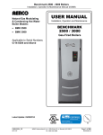
Cascade Sequencer Controller Front Panel
Latest Update: 11/25/2014
Page 1 of 26
PRI - 11/25/14
AERCO International, Inc. • 100 Oritani Dr. • Blauvelt, NY 10913
Ph.: 800-526-0288
OMM-0101_0A
GF-146-CS
AM Series Cascade Sequencer
Installation and Operation Manual
DISCLAIMER
The information contained in this manual is subject to change without notice from AERCO
International, Inc. AERCO makes no warranty of any kind with respect to this material, including,
but not limited to, implied warranties of merchantability and fitness for a particular application.
AERCO International is not liable for errors appearing in this manual, nor for incidental or
consequential damages occurring in connection with the furnishing, performance, or use of
these materials.
AERCO Technical Support:
(Mon–Fri, 8am-5pm EST)
1 (800) 526-0288
AERCO Document Conventions
In this document, some types of information are presented as shown in the following examples:
Message Type
Example and Description
Notes
NOTE messages indicate specific information related to the
surrounding contextual information, and highlighted for special
attention.
NOTE
CAUTION!
Cautions
CAUTION messages inform of potential problems relating to the
functioning of equipment, safety to persons, harm to the
environment, and/or damage to property or equipment.
WARNING!
Warnings
WARNING messages warn of potential dangerous situations that
may result in serious injury and/or death to persons or animals.
Text is red within a red box.
How Instructions are Presented
1. Instructions are shown in a blue box with an underlined title.
Instructions
2. All text, excepting in accompanying illustrations, is colored blue.
3. All procedures are listed in steps starting with “1.” and using
letters [a), b), c), etc.] indicating sub=steps.
4. Steps that are continued on the next page have a “(Cont.)”
appended to the instruction title.
Page 2 of 26
PRI - 11/25/14
AERCO International, Inc. • 100 Oritani Dr. • Blauvelt, NY 10913
Ph.: 800-526-0288
OMM-0101_0A
GF-146-CS
AM Series Cascade Sequencer
INSTALLATION AND OPERATION MANUAL
TABLE OF CONTENTS
INTRODUCTION .................................................................................................................. 4
CHAPTER 1: INSTALLATION ........................................................................................... 5
1.1 PIPING INSTALLATION .................................................................................................................... 5
1.2 ELECTRICAL INSTALLATION........................................................................................................... 6
1.3 MANAGER HEATER PREPARATION ............................................................................................... 8
1.3.1 Manager Heater Preparation - Communications Board ................................................................................... 8
1.3.2 Manager Heater Prep - S4 Switch on Communications Board ....................................................................... 12
1.3.3 Manager Heater Preparation - S4 Switch on the Burner #1 Board................................................................. 13
1.4 PREPARING THE CASCADE SEQUENCER FOR USE .................................................................. 14
1.5 SETTING THE LOGIC ADDRESS FOR EACH HEATER ................................................................. 15
1.6 SETTING FOR USE WITH BOILERS OR WATER HEATERS ......................................................... 17
1.7 DEPENDENT HEATER PREPARATION – SETTING PARAMETER 2003 ....................................... 17
1.7.1 AM Series Controller - Installer Menu Navigation .......................................................................................... 18
1.8 REVIEW OF ALL PARAMETERS .................................................................................................... 19
CHAPTER 2: OPERATION .............................................................................................. 20
2.1 CASCADE SEQUENCER DISPLAY AND CONTROLS .................................................................... 20
2.2 CASCADE STATUS BUTTON ......................................................................................................... 21
2.3 SUBMENU NAVIGATION, AND PARAMETER SETTINGS .............................................................. 21
2.4 SUBMENU PARAMETER LIST........................................................................................................ 23
2.5 MENU PARAMETER DESCRIPTIONS ............................................................................................ 22
2.6 TROUBLESHOOTING GUIDE ......................................................................................................... 24
OMM-0101_0A
GF-146-CS
AERCO International, Inc. • 100 Oritani Dr. • Blauvelt, NY 10913
Ph.: 800-526-0288
Page 3 of 26
PRI - 11/25/14
AM Series Cascade Sequencer
INSTALLATION AND OPERATION MANUAL
INTRODUCTION
The AM Series Cascade Sequencer controller is used to control a cascade arrangement of up
to eight (8) AM Series water heaters or boilers. This document provides instructions for
installation and operation of the cascade sequencer.
Please note that the cascade sequencer requires a communications board be installed in
each AM Series boiler or water heater. This board is present in every AM 500, 750, and
1000 but is an option on the AM 399 and must be installed prior to cascade sequencer
installation. For further information see the AM Series Modbus installation Guide (TID-0123).
Cascade Sequencer Controller Front Panel
The AM Series Cascade sequencer Kit is comprised of:
• AM Series Cascade Sequencer unit
• AM Series Cascade Sequencer User Manual (OMM-0101)
WARNING!
Installer: Read the manual for the appliance(s), including this
manual, before installing. Perform steps in the order given.
User: This manual is for use only by a qualified heating installer.
Failure to comply with these provisions can lead to a dangerous
situation and/or damage to property and equipment.
Installation and Alterations: Only a Qualified installer must carry
out the installation and calibration of the appliance(s). Never
modify the appliance or its flue gas carrying components in any
way. This heater must be properly vented. Failure to follow these
instructions could result in personal injury or death!
Page 4 of 26
PRI - 11/25/14
AERCO International, Inc. • 100 Oritani Dr. • Blauvelt, NY 10913
Ph.: 800-526-0288
OMM-0101_0A
GF-146-CS
AM Series Cascade Sequencer
INSTALLATION AND OPERATION MANUAL
CHAPTER 1: INSTALLATION
1.1 Piping Installation
WARNING!
Prior to appliance installation and/or maintenance, disconnect the
appliance’s electrical power supply and shut off the inlet gas
valve. Failure to follow these instructions could result in severe
personal injury or death!
In order for the AM Cascade Sequencer to operate correctly, the AM Series heaters must be
installed as shown in Figure 1-1.
Because the cascade general sensor is installed on the Manager heater, the managing heater
must always be the closest to the low loss header in order to provide the most accurate
temperature measurement.
A maximum of eight (8) heaters may be connected into the cascade system.
At the time of the installation all heaters will have the same settings. After installation, the heater
nearest the low loss header will require some hardware adjustment to become the managing
heater, and the other heaters will need a change to the software settings to become the
dependent heaters. Instructions for doing this are provided in the following sections.
NOTE
Figure 1-1 shows only one piping configuration example. Other
piping configurations are possible. Contact AERCO technical
support for information concerning alternative configurations.
Figure 1-1: Cascade Sequencing Heater/Boiler Piping Installation
OMM-0101_0A
GF-146-CS
AERCO International, Inc. • 100 Oritani Dr. • Blauvelt, NY 10913
Ph.: 800-526-0288
Page 5 of 26
PRI - 11/25/14
AM Series Cascade Sequencer
INSTALLATION AND OPERATION MANUAL
1.2 Electrical Installation
The electrical installation must be done as shown in Figure 1-2.
Installer must install all wires represented by dashed lines. The “Cascade general sensor” is
present inside each heater’s accessory box. This sensor must be electrically wired to terminals
24 and 25 of the Managing heater # 1 and placed into the low loss header of the cascade (see
Figure 1-1).
The "daisy chain" wiring used to connect boilers should be shielded type and has a
maximum length of 300 ft. Unshielded wire is acceptable but not recommended, and the
maximum length is only 60 ft.
Depending on the control method of your system, additional wiring may be required. For
outdoor reset using the included outdoor temperature sensor, connect the outdoor
temperature sensor to terminals 14 & 15 of the managing boiler. For remote setpoint (0-10V)
control, connect the 0-10V signal wires to terminals 22 & 23 of the master boiler. For Modbus
control of the operating setpoint connect to terminals 18, 19, and 20. For further information
on Modbus, see GF-146-MB.
If there is a water heater tank present in the system, whether direct or indirect, the tank
sensor should be placed in the bottom 1/3 of the tank and wired into terminals 12 & 13 of
the managing heater. This sensor is included in the spare parts kit shipped with each unit,
and is the same probe as the cascade header temperature sensor.
For further information on all of these control modes, consult the AM Series Boiler and
Water Heater User Manual (GF-146).
Page 6 of 26
PRI - 11/25/14
AERCO International, Inc. • 100 Oritani Dr. • Blauvelt, NY 10913
Ph.: 800-526-0288
OMM-0101_0A
GF-146-CS
AM Series Cascade Sequencer
INSTALLATION AND OPERATION MANUAL
Figure 1-2: Cascade Sequencing System Electrical Wiring
OMM-0101_0A
GF-146-CS
AERCO International, Inc. • 100 Oritani Dr. • Blauvelt, NY 10913
Ph.: 800-526-0288
Page 7 of 26
PRI - 11/25/14
AM Series Cascade Sequencer
INSTALLATION AND OPERATION MANUAL
1.3 Manager Heater Preparation
NOTE
Ensure that the heater being wired as the managing heater is the
one installed closest to the low loss header.
1.3.1 Manager Heater Preparation - Communications Board
To electrically prepare an AM Series heater/boiler for use as the Managing appliance for the
Cascade Sequencer, follow the instructions below.
Wiring the Manager Heater Communications Board
1. Gain access to the inside of the electrical junction box by removing the unit top cover and
the electrical junction box top cover (see Figure 1-3).
Unit Top Cover
Junction Box
Top Cover
Top Cover Screw
Communications
Board Cover
Figure 1-3: Accessing the Junction Box of the Managing Heater
2. Locate the communication board cover inside the junction box (see Figure 1-4).
Communications
Board Cover
Figure 1-4: Locating the Comm. Board inside the Electrical Junction Box
Page 8 of 26
PRI - 11/25/14
AERCO International, Inc. • 100 Oritani Dr. • Blauvelt, NY 10913
Ph.: 800-526-0288
OMM-0101_0A
GF-146-CS
AM Series Cascade Sequencer
INSTALLATION AND OPERATION MANUAL
Wiring the Manager Heater Communications Board – Continued
3. Using a flat head screwdriver, open the communications board cover (see Figure 1-5).
Figure 1-5: Using Screwdriver to Remove Communications Board Cover
4. Disconnect the 2-wire (pink/yellow) plug from the communications board (See Figure 1-6).
Communications
Board
Pink Wire
Yellow Wire
Unplug This
Male Connector
Unplug Connector
From Female Header
Figure 1-6: Removing 2-Wire Male Connector from Communications Board
5. Open the wire conduit cover (See Figure 1-7).
Wire
Conduit
Cover
Figure 1-7: Opening the Wire Conduit Cover
OMM-0101_0A
GF-146-CS
AERCO International, Inc. • 100 Oritani Dr. • Blauvelt, NY 10913
Ph.: 800-526-0288
Page 9 of 26
PRI - 11/25/14
AM Series Cascade Sequencer
INSTALLATION AND OPERATION MANUAL
Wiring the Manager Heater communications Board – Continued
6. From the wire conduit, remove the two wires (pink and yellow) that are attached to the plug
disconnected from the communications board in step 4.
Wire
Conduit
Figure 1-8: Removing Pink and Yellow Wires from Wire Conduit
7. Cut the connector from the pink and yellow wires and strip the insulation 1/4” (7mm).
Yellow & Pink
wires cut from
connector
and stripped.
Figure 1-9: Removing 2-Wire Connector from Junction PCB
8. Connect the pink wire together with the two black wires present on terminal #16 (See
Figures 1-10 and 1-12).
Figure 1-10: Connecting Pink Wire to Terminal #16
Page 10 of 26
PRI - 11/25/14
AERCO International, Inc. • 100 Oritani Dr. • Blauvelt, NY 10913
Ph.: 800-526-0288
OMM-0101_0A
GF-146-CS
AM Series Cascade Sequencer
INSTALLATION AND OPERATION MANUAL
Wiring the Manager Heater Communications Board – Continued
9. Connect the yellow wire together with the two red wires present on terminal #17 (See
Figures 1-11 and 1-12).
Figure 1-11: Connecting Yellow Wire to Terminal #17
Connect PINK Wire
To Terminal #16
Connect YELLOW Wire
To Terminal #17
Existing BLACK Wires
On Terminal #16
Existing RED Wires
On Terminal #17
Figure 1-12: Terminal Wiring Diagram for Managing Heater
NOTE
Other wiring is not shown for diagram clarity.
OMM-0101_0A
GF-146-CS
AERCO International, Inc. • 100 Oritani Dr. • Blauvelt, NY 10913
Ph.: 800-526-0288
Page 11 of 26
PRI - 11/25/14
AM Series Cascade Sequencer
INSTALLATION AND OPERATION MANUAL
1.3.2 Manager Heater Prep - S4 Switch on Communications Board
The S4 switch on the communications board must be set to ON as described below.
Setting Manager Heater Communications Board S4 Switch to ON
1. Locate the communications board at top of unit per previous wiring instructions.
2. Locate S4 switch at front edge of communications board per Figure 1-13.
3. Set S4 switch to ON (LEFT as you are facing the unit) per Figure 1-13.
S4
Switch
Figure 1-13: Setting Managing Heater Communications Board S4 Switch
NOTE
Wiring is not shown for image clarity.
Page 12 of 26
PRI - 11/25/14
AERCO International, Inc. • 100 Oritani Dr. • Blauvelt, NY 10913
Ph.: 800-526-0288
OMM-0101_0A
GF-146-CS
AM Series Cascade Sequencer
INSTALLATION AND OPERATION MANUAL
1.3.3 Manager Heater Preparation - S4 Switch on the Burner #1 Board
The S4 switch on the Burner #1 (Master) board must be set to OFF as described below.
Setting Manager Heater Burner #1 (Master) S4 Switch
1. Gain access to the Burner #1 (Master) Board and S4 switch by removing the front cover of
managing unit. Note the location of the Burner #1 (Master) Board in Figure 1-14 (it is cyan
colored in the image).
NOTE
The model shown in Figure 1-14 is the AM1000. The AM750 does
not feature Burner Board #2. In the AM399 and AM500 models,
the #1 (Master) Burner board is the one on the BOTTOM.
2. Locate S4 switch opening on upper right of #1 burner board (Figure 1-14) and use a small
flathead screwdriver set to switch to OFF (UP) per Figure 1-14 detail.
Burner #2 Board (Not Present in
AM750 Units)
S4
Switch
OFF
ON
STEP 2: Set S4 Switch to OFF (UP)
(Board Cover removed for clarity)
Burner #1 (Master) Board
Burner #3 Board
Burner #4 Board
Figure 1-14: Locating Burner #1 (Master) Board and Setting S4 Switch
OMM-0101_0A
GF-146-CS
AERCO International, Inc. • 100 Oritani Dr. • Blauvelt, NY 10913
Ph.: 800-526-0288
Page 13 of 26
PRI - 11/25/14
AM Series Cascade Sequencer
INSTALLATION AND OPERATION MANUAL
1.4 Preparing the Cascade Sequencer for Use
The Cascade Sequencer is used to program the logic address of each heater, as well as control
the final cascade system, and must be wired as described below.
Preparing the Cascade Sequencer for Use
1. Using a small flat head screwdriver, remove the rear cover of the Cascade Sequencer by
levering up the panel via the slot, as shown in Figure 1-15.
Using
Screwdriver
in Slot
Cascade
Sequencer
Rear Panel
Figure 1-15: Opening Rear Panel of Cascade Sequencer
2. Connect two wires, each two feet (0.5m) long, to the two screw terminals on the Cascade
Sequencer PCB, as shown in Figure 1-16. Wires do not have polarity.
Install Wires
into Terminals
Figure 1-16: Connecting Wires to the Cascade Sequencer Terminals
Page 14 of 26
PRI - 11/25/14
AERCO International, Inc. • 100 Oritani Dr. • Blauvelt, NY 10913
Ph.: 800-526-0288
OMM-0101_0A
GF-146-CS
AM Series Cascade Sequencer
INSTALLATION AND OPERATION MANUAL
Preparing the Cascade Sequencer for Use - Continued
3. Feed both wires through the rear panel conduit opening and snap rear panel onto rear of
cascade Sequencer (Figure 1-17).
Figure 1-17: Replacing Cascade Sequencer Rear Panel after Wiring
1.5 Setting the Logic Address for Each Heater
Program the logic address of each heater using the Cascade Sequencer as described below.
Setting the Logic Address for Each Heater
NOTE
Refer to Section 1.31 for location of the electrical junction
enclosure and wiring terminals mentioned below. See Section 2
for how to operate the unit and access menus and parameters.
1. Ensure power is turned OFF to the Managing heater #1.
2. Connect the two wires from the Cascade Sequencer to terminals 16 and 17 of the Managing
heater # as shown in Figure 1-18.
Figure 1-18: Wiring Cascade Sequencer to Terminals 16 and 17
NOTE
The wiring diagram shown in Figure 1-18 applies to all heaters in
cascade, as each will be programmed with a unique logic address
using the Cascade Sequencer. Other wiring is not shown for
clarity.
OMM-0101_0A
GF-146-CS
AERCO International, Inc. • 100 Oritani Dr. • Blauvelt, NY 10913
Ph.: 800-526-0288
Page 15 of 26
PRI - 11/25/14
AM Series Cascade Sequencer
INSTALLATION AND OPERATION MANUAL
Setting the Logic Address for Each Heater - Continued
3. Turn the power ON to the Managing heater #1. The Cascade Sequencer will also power up.
4. Wait until the Cascade Sequencer recognizes the boiler and “E2Prom Err” is not displayed.
5. Using the Cascade Sequencer, set the Address to 1 as follows:
Logic Address Programming Procedure
a) Press and hold the Home button (Figure 2-1) for eight (8) seconds, then release the
button to display the Sub menu.
b) Once the Sub menu is displayed (Figure 1-19), use the Up or Down buttons (Figure
2-1) to scroll through the list of parameters. A dot appears to the left of the parameter
to indicate it is selected (Figure 1-19).
Dot indicating
selected parameter
Figure 1-19: Sub Menu - Selecting the Parameter to Change
c) When the Boiler Address parameter is selected, press the Ok button. The dot will
then move to the left of the parameter setting (Figure 2-4), which begins to blink,
indicating it may be adjusted.
Dot indicating
parameter setting
may be changed
(Setting also blinks)
Figure 1-20: Sub Menu – Changing the Parameter Setting
d) Use the Up or Down buttons to change the parameter value up or down. For the
Managing heater, set this to 1. For each Dependent heater, a different address is set,
from 2 to 7, depending on how many dependent heaters in the cascade.
e) When the desired logic address number is displayed, save it by pressing the Ok
button. To reject the change, do not press OK, and instead skip to the next step.
f) To return to the Main menu, press the Menu button (Figure 2-1).
g) Wait a minimum of 4 seconds or until “#1” appears in the upper left of the center box
of the sequencer display.
IMORTANT NOTE!
After any change to a parameter, wait at least 40 seconds before
exiting the sub menu or turning the power off.
6. Turn the power off to the Managing heater #1.
7. Disconnect the two wires from terminals 16 and 17 of the Managing heater #1
8. Connect the two wires from the Cascade Sequencer to terminals 16 and 17 of the
Dependent heater #2.
9. On the communications board at top of unit, set the S4 Switch (see Figure 1-13) to ON.
10. Turn the power ON to the Dependent heater #2.
Page 16 of 26
PRI - 11/25/14
AERCO International, Inc. • 100 Oritani Dr. • Blauvelt, NY 10913
Ph.: 800-526-0288
OMM-0101_0A
GF-146-CS
AM Series Cascade Sequencer
INSTALLATION AND OPERATION MANUAL
Setting the Logic Address for Each Heater - Continued
11. Repeat steps a) through g) in Step 5 setting the logic address to 2.
12. Turn the power OFF to the Dependent heater #2.
13. On the communications board at top of unit, set the S4 Switch (see Figure 1-13) to the OFF
position.
14. Disconnect the two wires from terminals 16 and 17 of the Dependent heater #2.
15. Repeat steps 1 to 13 on each dependent heater and set the Address sequentially for each
one (2, 3, 4, 5, etc.).
16. After all dependent heaters have had the logic address set, wire the Cascade Sequencer to
terminals 16 and 17 of the Managing heater #1. The Cascade Sequencer is now set up for
cascade operation. Ensure all switch settings match Figure 1-18.
1.6 Setting for Use with Boilers or Water Heaters
The Cascade Sequencer is set at the factory for boiler applications, but not for water heater
applications. When your system is in place, and you wish to control water heaters, you must
ensure all parameters of the Sub Menu are set as shown in the list in Section 2.1. Select the
settings in the column for boilers if you are using boilers, or select the settings in the column for
water heaters if you are using water heaters.
1.7 Dependent Heater Preparation – Setting Parameter 2003
Parameter 2003 is factory set to 0. However, this parameter should be checked for all
dependent heaters to ensure parameter 2003 is set to 0.
Follow the instructions in Section 1.71 (next page) to access the Installer Menu on the AM
Series boiler or water heater controller to confirm or change parameter 2003 to zero for all
dependent heaters. If you need more information concerning AM Series controller operation,
consult the AERCO AM Series user manual (GF-146).
OMM-0101_0A
GF-146-CS
AERCO International, Inc. • 100 Oritani Dr. • Blauvelt, NY 10913
Ph.: 800-526-0288
Page 17 of 26
PRI - 11/25/14
AM Series Cascade Sequencer
INSTALLATION AND OPERATION MANUAL
1.7.1 AM Series Controller - Installer Menu Navigation
This menu of parameters is available to qualified technicians for the purpose of analyzing the
function of, and making adjustments to, the unit.
Parameters for “Burner 1” are applicable for that burner only.
To enter and make changes in the Installer Menu, perform the following steps:
AM Series Controller - Installer Menu Navigation and Adjustment
1. To enter the Installer Menu, press and simultaneously hold down both the RESET and
buttons or 5 seconds until the icon is displayed.
, then release the buttons.
After entering the Installer Menu, the 2000 series of parameters are available for display and
editing.
2. To scroll through the list of parameters, press buttons
and
.
3. Once parameter 2003 is displayed, it can be selected for editing by pressing the RESET
button once (the displayed value will start blinking) and then using the
buttons to change the value, up or down. For dependent eaters, select 0.
and
4. To confirm the new value, press and release the RESET button.
5. To exit the Installer Menu, press and hold RESET button for more than 5 seconds until the
icon is no longer shown in the display.
NOTE
This instruction is only for setting parameter 2003. For information
about other parameters in the Installer Menu, refer to the AM
Series user manual (GF-146).
Page 18 of 26
PRI - 11/25/14
AERCO International, Inc. • 100 Oritani Dr. • Blauvelt, NY 10913
Ph.: 800-526-0288
OMM-0101_0A
GF-146-CS
AM Series Cascade Sequencer
INSTALLATION AND OPERATION MANUAL
1.8 Review of All Parameters
Figure 1-18 diagrams a cascade setup using three (3) AM1000 units (with four burner boards in
each unit).
At the end of the installation process, all parameters (Address; Switch S4; 2003; 3001 and
3050) should have the values as shown on Figure 1-18.
If an attempt is made to operate the cascade system and the applicable parameters are not set
to the values shown in Figure 1-18, one or more of the heaters in the cascade will display a 116
error (communication error) and will stop functioning.
Figure 1-18: Cascade General Configuration and Settings Diagram
OMM-0101_0A
GF-146-CS
AERCO International, Inc. • 100 Oritani Dr. • Blauvelt, NY 10913
Ph.: 800-526-0288
Page 19 of 26
PRI - 11/25/14
AM Series Cascade Sequencer
INSTALLATION AND OPERATION MANUAL
CHAPTER 2: OPERATION
NOTE
After turning on power, wait at least 40 seconds for
communication between sequencer and heaters to finish before
performing any operations. Wait for the cascade manager to
recognize the address of the master boiler or water heater.
2.1 Cascade Sequencer Display and Controls
The AM Series Cascade Sequencer features a display and lower cover that is opened to reveal
a number of buttons, as shown in Figure 2-1.
The icons labeled "M" and "D" represent the firing rate and current state of the first and
second burners on the master unit and are not important to the function of the cascade
manager.
If the outdoor temperature sensor is not connected it will display a temperature of "-40".
Similarly, if the cascade temperature sensor is not connected it will display a temperature of
roughly 12-14 degrees.
Logic Address
Cascade Setpoint
Cascade Temperature
Outdoor
Temperature
Information
Field
Information
Light
Cascade
Status
Button
Information
Button
(Not Used)
Reset
Button
(Not Used)
(Not Used)
OK Button
To Select
Parameters &
Accept
Changes
Open
Cover
HOME Button
DOWN/UP Buttons
(Press 8 sec. to enter Sub-Menu)
To Scroll Thru Parameter List
MENU Button
or Parameter Values
(Exit Sub-menu)
Figure 2-1: Cascade Sequencer Front Panel Features (Lower Cover Open)
Page 20 of 26
PRI - 11/25/14
AERCO International, Inc. • 100 Oritani Dr. • Blauvelt, NY 10913
Ph.: 800-526-0288
OMM-0101_0A
GF-146-CS
AM Series Cascade Sequencer
INSTALLATION AND OPERATION MANUAL
2.2 Cascade Status Button
By pressing the Cascade Status button (Figure 2-1), the lower half of the display will change to
show the status of the cascade boilers (Figure 2-2). The designated number for each boiler in
the cascade system will be displayed, such as 1, 2, 3, 4, etc., up to 8. If there is a request for
heating for any heater, a flame icon will appear under that heater’s number. The absence of a
flame icon under the number represents a heater in standby mode.
The Cascade Status display shown in Figure 2-2 indicates there are three heaters in the
cascade, with numbers 1 and 2 calling for heat, and number 3 in standby mode.
Number
Indicating
Cascade
Heater
Flame Icon
Indicates a
Request for Heat
No Flame Icon Indicates
Heater is in Standby Mode
Figure 2-2: Cascade Status Display (When Cascade Button Pressed)
2.3 Submenu Navigation, and Parameter Settings
The sub-menu may be accessed, navigated, and parameters changed as instructed below.
Submenu Navigation and Parameter Settings
1. Press and hold the Home button (Figure 2-1) for eight (8) seconds, then release the button
to display the Sub menu.
2. Once the Sub menu is displayed (Figure 2-3), use the Up or Down buttons (Figure 2-1) to
scroll through the list of parameters. A dot appears to the left of the parameter to indicate it
is selected.
Dot indicating
selected
parameter
Figure 2-3: Sub Menu - Selecting the Parameter to Change
3. When the desired parameter is displayed, press the Ok button. The dot will then move to
the left of the parameter setting (Figure 2-4), which begins to blink, indicating it may be
adjusted.
Dot indicating
parameter setting may
be changed
(Setting also blinks)
Figure 2-4: Sub Menu – Changing the Parameter Setting
OMM-0101_0A
GF-146-CS
AERCO International, Inc. • 100 Oritani Dr. • Blauvelt, NY 10913
Ph.: 800-526-0288
Page 21 of 26
PRI - 11/25/14
AM Series Cascade Sequencer
INSTALLATION AND OPERATION MANUAL
Submenu Navigation and Parameter Settings – Continued
4. Use the Up or Down buttons to change the parameter value up or down.
5. When the desired value is displayed, save it by pressing the Ok button. To reject the
change, do not press OK, and instead skip to the next step.
6. To leave the Sub Menu and return to the Main menu, press the Menu button (Figure 2-1).
IMPORTANT NOTE!
After any change to a parameter, wait at least 40 seconds before
exiting the sub menu or turning the power off.
2.4 Sub-Menu Parameter Descriptions
Below is a list of Menu parameters and descriptions. The table in the next section lists the range
and default settings for each parameter.
AM Series Cascade Sequencer Parameter Descriptions
Parameter Name
Parameter Description
Boiler address
Logic boiler address
Cascade setpoint
Cascade general sensor setpoint
DHW ON..OFF
Enable / disable control for an indirect water heater
Start delay time
Delay for a call of the next boiler
Stop delay time
Delay to remove the call to the next boiler
Start boiler diff
Temperature differential to call the next boiler
Stop boiler diff
Temperature differential to remove the call to the next boiler
Stop all boiler diff
Temperature differential to remove the call to all boilers
Max offset up
Maximum difference above the header setpoint that any one boiler is allowed to
reach.
Max offset down
Maximum difference below the header setpoint that any one boiler is allowed to
reach.
Rotation interval
How often the “lead” boiler is rotated.
P Value
Proportional band of the PID temperature control of the cascade general sensor
I Value
Integral band of the PID temperature control of the cascade general sensor
D Value
Derivative band of the PID temperature control of the cascade general sensor
Slew rate
Slew rate is a low level parameter. It determines how fast the output of a PID can
change per amount of time.
System correction
The system correction value is added to the measured system temperature. This
corrected value is used for control. If the measured sensor value deviates from the
real temperature then you can correct it with this parameter.
Mod delay factor
Delay to the start of modulation of any boiler.
Page 22 of 26
PRI - 11/25/14
AERCO International, Inc. • 100 Oritani Dr. • Blauvelt, NY 10913
Ph.: 800-526-0288
OMM-0101_0A
GF-146-CS
AM Series Cascade Sequencer
INSTALLATION AND OPERATION MANUAL
2.5 Sub-menu Parameter Range and Default settings
Below is a list of the menu parameters with range and default settings. There is a table in the
previous section that provides a description of each parameter.
AM Series Cascade Sequencer Sub-Menu Parameter List
Parameter
Units Range
Boiler address
Factory
Settings
Boiler Settings
Water Heater
Settings
0 - Stand Alone heater
1 – Managing Heater
2 – 1st Dependent Heater
3 – 2nd Dependent Heater
4 – 3rd……etc
140
ON (only if you want to drive
an indirect water heater)
0 - Stand Alone heater
1 – Managing Heater
2 – 1st Dependent Heater
3 – 2nd Dependent Heater
4 – 3rd……etc
140
/
0 …..16
0
°F
68..194
140
DHW ON..OFF
/
ON..OFF
OFF
Start delay time
Stop delay time
sec
sec
0..1200
0..1200
180
180
Start boiler diff
Stop boiler diff
180
180
15
15
°F
°F
14..36
14..59
14
14
14
14
Stop all boiler diff
Max offset up
14
14
°F
°F
14..59
14..50
24
17
24
24
Max offset down
Rotation interval
17
14
°F
Days
14..50
1..10
37
5
P Value
I Value
37
5
14
5
/
/
0..255
0..255
20
80
20
20
D Value
Slew rate
80
80
/
/
0..255
1..255
0
5
0
5
0
5
14..32
0..60
22.1
4
22.1
22.1
4
0
Cascade setpoint
System correction °F
Mod delay factor
min
OMM-0101_0A
GF-146-CS
AERCO International, Inc. • 100 Oritani Dr. • Blauvelt, NY 10913
Ph.: 800-526-0288
Custom
Value
OFF
Page 23 of 26
PRI - 11/25/14
AM Series Cascade Sequencer
INSTALLATION AND OPERATION MANUAL
2.6 Troubleshooting Guide
Below is a list of possible issues and corrective actions.
Troubleshooting Guide
Issue
Corrective Action
Cannot set the unit address
when installing cascade
sequencer
OR
When trying to set the unit
address, the new address
does not appear on the
cascade sequencer.
Cascade system does not
seem to be communicating
correctly.
• Double check all wiring.
• Ensure settings and switches are correct as per Figure 1-18.
• Double check all wiring.
• Ensure settings and switches are correct as per Figure 1-18.
• Make sure that all units show up under the Cascade Status
menu.
When trying to set the unit
address, “#5” appears on all
units.
This may indicate incorrect software in the communications
module.
Contact AERCO technical support for further
information.
Domestic water heating tank is
not reacting quickly.
Check that the parameters are all set according to the “Water
Heater Settings”.
• Check the location of the cascade header temperature
sensor. Ensure that the sensor is located such that it will
see flow from both the primary and secondary loops.
System loop is not reaching
desired setpoint.
• Check parameters 1120-1123 on each unit. Ensure that all
modules are running at maximum capacity. If not, wait 10
minutes for burners to modulate up and check again.
• Change System Correction factor from 14 to 22.1.
• Check each unit’s outlet temperature on the individual boiler
or water heater interface. If Cascade Setpoint + Max Offset
Up is less than or equal to any individual unit’s outlet
temperature, increase the Max Offset Up parameter.
Outdoor air temperature
sensor on cascade sequencer
shows “-40”.
Cascade sequencer header
temperature displays a low
value (10-16°F).
Page 24 of 26
PRI - 11/25/14
• Check that the sensor is wired to terminals 14 & 15 of the
master boiler.
• Make sure all electrical connections are tight.
• Check sensor resistivity.
Check that the cascade header temperature sensor is
installed in terminals 24 & 25 of the master boiler or water
heater.
AERCO International, Inc. • 100 Oritani Dr. • Blauvelt, NY 10913
Ph.: 800-526-0288
OMM-0101_0A
GF-146-CS
AM Series Cascade Sequencer
INSTALLATION AND OPERATION MANUAL
NOTES:
OMM-0101_0A
GF-146-CS
AERCO International, Inc. • 100 Oritani Dr. • Blauvelt, NY 10913
Ph.: 800-526-0288
Page 25 of 26
PRI - 11/25/14
AM Series Cascade Sequencer
INSTALLATION AND OPERATION MANUAL
Change Log:
Date
Description
Changed By
11/25/2014
Rev-A: Released
Curtis Harvey
International, Inc.
www.aerco.com
Page 26 of 26
PRI - 11/25/14
AERCO International, Inc. • 100 Oritani Dr. • Blauvelt, NY 10913
Ph.: 800-526-0288
OMM-0101_0A
GF-146-CS