1
User's
Manual
Models AM100D, AM200D,
AM300D, AM400D, and AM500D
Magnetic Flow Tube
IM 1E6D0-01E
IM 1E6D0-01E
17th Edition
CONTENTS
CONTENTS
1.
INTRODUCTION .......................................................................................... 1-1
2.
HANDLING PRECAUTIONS ....................................................................... 2-1
2.1
2.2
2.3
2.4
2.5
3.
Checking Model and Specifications .................................................... 2-1
Accessories ......................................................................................... 2-1
Storage Precautions ............................................................................ 2-1
Installation Location Precautions ........................................................ 2-1
Terminal Box Reorientation Precautions ............................................ 2-1
INSTALLATION ........................................................................................... 3-1
3.1
3.2
Piping Design Precautions .................................................................. 3-1
Handling Precautions .......................................................................... 3-3
3.2.1 General Precautions ..................................................................... 3-3
3.2.2 Flow Tube Piping ......................................................................... 3-4
3.3 Mounting .............................................................................................. 3-5
3.3.1 Nominal Diameter 2.5 mm (0.1˝) to 10 mm (0.4˝)
Union Joint Type .......................................................................... 3-5
3.3.2 Nominal Diameter 2.5mm (0.1˝) to 40mm (1.5˝) Wafer Type ..... 3-6
3.3.3 Nominal Diameter 50 mm(2˝) to 200 mm(8˝) Wafer Type .......... 3-9
3.3.4 Nominal Diameter 15 mm (0.5˝) to 400 mm (16˝)
Flange Type ............................................................................... 3-12
3.3.5 Mominal Diameter 500 mm (20˝) to 2600 (104˝)
Flange Type ............................................................................... 3-14
3.3.6 Mounting Procedure for Sanitary Type ...................................... 3-15
3.4 Wiring Precautions ............................................................................ 3-16
3.4.1 Protective Grounding .................................................................. 3-16
3.4.2 General Precautions ................................................................... 3-16
3.4.3 Cable Types ............................................................................... 3-16
3.4.4 Connnection to AM11Magnetic Flow Converter ........................ 3-17
3.4.5 Wiring Ports ................................................................................ 3-18
4.
MAINTENANCE ........................................................................................... 4-1
4.1
4.2
Regular Inspection Items .................................................................... 4-1
Trouble Shooting ................................................................................. 4-1
5.
OUTLINE ...................................................................................................... 5-1
6.
HAZARDOUS DUTY TYPE INSTRUMENT ................................................ 6-1
6.1
6.2
6.3
6.4
FM ....................................................................................................... 6-1
CSA ..................................................................................................... 6-2
CENELEC (KEMA) .............................................................................. 6-2
JIS ....................................................................................................... 6-3
INSTALLATION AND OPERATING PRECAUTIONS FOR JIS FLAMEPROOF
EQUIPMENT ...................................................................................... EX-B03E
FD No. IM 1E6D0-01E
17th Edition: Nov. 2002 (YG)
IM 1E7D0-01E
All
Rights Reserved, Copyright © 1990, Yokogawa Electric Corporation
i
1. INTRODUCTION
1.
INTRODUCTION
The following safety symbol marks are used in
this manual and instrument;
This instrument has been already adjusted at the
factory before shipment.
To ensure correct use of the instrument, please read
this manual thoroughly and fully understand how to
operate the instrument before operating it.
WARNING
A WARNING sign denotes a hazard. It calls
attention to procedure, practice, condition or the
like, which, if not correctly performed or adhered
to, could result in injury or death of personnel.
䊏 Regarding This Manual
• This manual should be passed on to the end user.
• Before use, read this manual thoroughly to comprehend its contents.
• The contents of this manual may be changed
without prior notice.
• All rights reserved. No part of this manual may be
reproduced in any form without Yokogawa’s written
permission.
• Yokogawa makes no warranty of any kind with
regard to this material, including, but not limited to,
implied warranties of merchantability and suitability
for a particular purpose.
• All reasonable effort has been made to ensure the
accuracy of the contents of this manual. However, if
any errors are found, please inform Yokogawa.
• Yokogawa assumes no responsibilities for this
product except as stated in the warranty.
• If the customer or any third party is harmed by the
use of this product, Yokogawa assumes no responsibility for any such harm owing to any defects in the
product which were not predictable, or for any
indirect damages.
CAUTION
A CAUTION sign denotes a hazard. It calls
attention to procedure, practice, condition or the
like, which, if not correctly performed or adhered
to, could result in damage to or destruction of
part or all of the product.
IMPORTANT
A IMPORTANT sign denotes an attention to
avoid leading to damage to instrument or system
failure.
NOTE
䊏 Safety Precautions
• The following general safety precautions must be
observed during all phases of operation, service, and
repair of this instrument. Failure to comply with
these precautions or with specific WARNINGS
given elsewhere in this manual violates safety
standards of design, manufacture, and intended use
of the instrument. YOKOGAWA Electric Corporation assumes no liability for the customer’s failure to
comply with these requirements. If this instrument is
used in a manner not specified in this manual, the
protection provided by this instrument may be
impaired.
A NOTE sign denotes a information for essential
understanding of the operation and features.
Protective grounding terminal.
Function grounding terminal. This terminal
should not be used as a “Protective grounding
terminal”.
Alternating current.
Direct current.
1-1
IM 1E6D0-01E
1. INTRODUCTION
䊏 Warranty
• The guaranteed term of this instrument is described
in the quotation. We repair the damages that
occurred during the guaranteed term for free.
• Please contact with our sales office when this
instrument is damaged.
• If the instrument has trouble, please inform us
model code, serial number, and concrete substances
or situations. It is preferable to be attached a outline
or data.
• We decide after the examination if free repair is
available or not.
• Please consent to the followings for causes of
damages that are not available as free repair, even if
it occured during the guaranteed term.
A: Unsuitable or insufficient maintenance by the
customer.
B: The handling, using, or storage that ignore the
design and specifications of the instrument.
C: Unsuitable location that ignore the description in
this manual.
D: Remaking or repair by a person except whom we
entrust.
E: Unsuitable removing after delivered.
F: A natural disaster (ex. a fire, earthquake, storm and
flood, thunderbolt) and external causes.
For the safety using;
WARNING
• The Magnetic Flow Tube is a heavy instrument.
Please give attention to prevent that persons
are injured by carrying or installing. It is preferable for carrying the instrument to use a cart
and be done by two or more persons.
• In wiring, please confirm that the cables are not
powered before connecting.
• When removing the instrument from hazardous
processes, avoid contact with the fluid and the
interior of the meter.
• In case of Hazardous duty type instrument,
further requirements and differences are
described in Chapter 6 “HAZARDOUS DUTY
TYPE INSTRUMENT”. The description in
Chapter 6 is prior to other description in this
instruction manual.
1-2
IM 1E6D0-01E
2. HANDLING PRECAUTIONS
2.
HANDLING PRECAUTIONS
This instrument has been already tested thoroughly at
the factory. When the instrument is delivered, please
check externals and make sure that no damage
occurred during transportation.
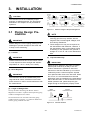
2.3 Storage Precautions
In this chapter, handling precautions are described.
Please read this chapter thoroughly at first. And please
refer to the relative matter about other ones.
• The instrument should be stored in its original
packing condition.
• The storage location should be selected according to
the following conditions:
1) The location where it is not exposed to rain or
water.
2) The location where there is few vibration or
shock.
3) Temperature and humidity should be:
Temperature: –30 to 60˚C (–22 to 140˚F)
Humidity:
5 to 80% RH (no condensation)
Preferable ambient temperature and humidity
are 25˚C(77˚F) and about 65% RH.
In case the instrument is expected to be stored over a
long term, please give attention to the followings;
If you have any problems or questions, please make
contact with Yokogawa sales office.
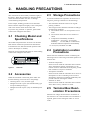
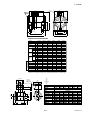
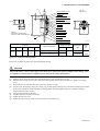
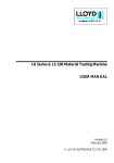
2.1 Checking Model and
Specifications
The model and specifications are shown on the Data
Plate. Please confirm the specifications between the
instrument that was delivered and the purchase order
(refer to the chapter 5. Outline).
2.4 Installation Location
Precautions
Please let us know Model and Serial No. when making
contact with Yokogawa sales office.
MAGNETIC
FLOW DETECTOR
AM
Please select the installation location considering the
following items to ensure long term stable operation of
the flow tube.
mm
L
H
• Ambient Temperature:
Please avoid to install the instrument at the location
where temperature changes continuously. If the
location receives radiant heat from the plant, provide
heat insulation or improve ventilation.
• Atmospheric Condition:
Please avoid to install the instrument in an corrosive
atmosphere. In case of installing in the corrosive
atmosphere, please keep ventilating sufficiently and
prevent rain from entering the conduit.
• Vibration or shock:
Please avoid to install the instrument at the location
where there is heavy vibration or shock.
Made in Japan
F0201.EPS
Figure 2.1
Data Plate
2.2 Accessories
When the instrument is delivered, please make sure
that the following accessories are in the package.
• Centering device 1-set (for wafer type)
• Hexagonal wrench 1-piece (for hazardous duty type
except JIS flameproof type)
• Hexagonal wrench 2-piece (only for JIS flameproof
type)
2.5 Terminal Box Reorientation Precautions
Please do not change the terminal box orientation at
the customer’s site. If the terminal box reorientation is
required, please contact Yokogawa office or service
center.
2-1
IM 1E6D0-01E
3. INSTALLATION
3.
INSTALLATION
Gate valve
fully open
CAUTION
This instrument must be installed by expert
engineer or skilled personnel. The procedures
described in this chapter are not permitted for
operators.
Reducer pipe
5 D or more 2 D or more
Tee
Do not care to 0 D
90° degrees bent
5 D or more Do not care to 0 D
5 D or more
D: Nominal diameter of flow tube
Expander pipe
Do not care to 0 D
10 D or more 2 D or more
Various types of valves
Do not care to 0 D
10 D or more
2 D or more
F030101.EPS
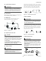
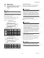
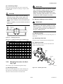
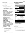
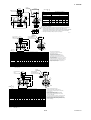
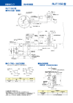
Figure 3.1.1
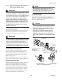
3.1 Piping Design Precautions
Minimum Length of Required Straight Run
NOTE
1. Nothing must be inserted or installed in the
metering pipe than may interfere with the
magnetic field, induced signal voltages, and
flow velocity distribution.
2. These straight runs may not be required on
the downstream side flowmeter. However, if
the downstream valve or other fittings cause
channeling on the upstream side, provide a
straight run of 2 D to 3 D on the downstream
side.
IMPORTANT
Please design the correct piping referring to the
followings to prevent damage for flow tube and
to keep correct measuring.
(1) Location
(4) Liquid Conductivity
IMPORTANT
Please install the flow tube to the location where
it is not exposed to direct sunlight and ambient
temperature is –10 to + 60°C (14 to 140°F).
IMPORTANT
Please avoid to install the flow tube at location
where liquid conductivity is likely to be nonuniform. Because it is possible to have bad
influences to the flow indication by non-uniform
conductivity when a chemical liquid is injected
from upstream side close to the flow tube. When
this occurs, it is recommended that chemical
application ports are installed on the downstream
side of the flow tube. In case chemicals must be
added upstream side, please keep the pipe
length enough so that liquid is properly mixed.
(2) Noise Rejection
IMPORTANT
The instrument should be installed away from
large electrical motors, transformers and other
power sources in order to avoid interference with
the measurement.
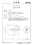
(3) Length of Straight Run
To keep accurate measuring, JIS B7554 “Electro
Magnetic Flow Tubes” explains about upstream piping
condition of Magnetic Flow Tubes.
(BAD)
Upstream side
(GOOD)
Downstream side
We recommend to our customers about the piping
conditions shown in Figure 3.1.1 based on JIS B7554
and our piping condition test data.
F030102.EPS
Figure 3.1.2
3-1
Chemical Insertion
IM 1E6D0-01E
3. INSTALLATION
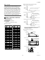
(5) Liquid Sealing Compound
Please design the piping that a fluid is always filled in
the pipes. The Vertical Mounting is effective for fluids
that is easily separate or slurry settles within pipes.
IMPORTANT
In this case, please flow a fluid from bottom to up.
Please give attention in using Liquid Sealing
Compound to the piping, because it brings bad
influences to measurement by flowing out and
cover the surfaces of electrode and earth-ring.
(BAD)
(GOOD)
h
(GOOD)
(BAD)
h>0
h
h>0
Horizontal mounting
(6) Service Area
Please select the location where there is enough area to
service installing, wiring, overhaul, etc.
Figure 3.1.4
Vertical mounting
F030104.EPS
Filling the Pipe with Liquid
(10) No Air Bubbles
(7) Bypass Line
It is recommended to install the Bypass Line to
facilitate maintenance and zero adjustment.
IMPORTANT
Please give attention to prevent bad influences
or measuring errors from air bubbles that gathers inside measuring pipes.
Bypass valve
Block
valve
In case the fluid includes air bubbles, please design the
piping that prevent to gather air bubbles. In case valves
are installed upstream of the flow tube, it is possible
that a valve causes air bubbles, please install the flow
tube upstream side of a valve.
Block valve
F030103.EPS
Figure 3.1.3
Bypass Line
(GOOD)
(BAD)
(GOOD)
(BAD)
(8) Supporting the Flow Tube
F030105.EPS
Figure 3.1.5
Avoiding Air Bubbles
CAUTION
(11) Mounting Direction
Please avoid to support only the flow tube, but
fix pipes at first and support the flow tube by
pipes to protect the flow tube from forces caused
by vibration, shock, expansion and contraction
through piping.
For small sized flow tubes, please provide a
mounting base so thet the tubes are fixed in the
piping. See the section 3.3 Mounting.
IMPORTANT
When the electrodes are vertical to ground, the
electrode is covered with air bubbles at upper
side or slurry at downside, and it may cause the
measuring errors.
Please be sure to mount the terminal box upper
side of piping to prevent water penetration into
terminal box.
(9) Piping Condition
(Good)
IMPORTANT
(No good)
(No good)
The piping should be designed so that a full pipe
is maintained at all times to prevent loss of
signal and erroneous readings.
Air Bubbles
Electrodes
Electrodes
Slurry
Water slowly
percolates
downward into
terminal box.
F030106.EPS
Figure 3.1.6
3-2
Mounting Direction
IM 1E6D0-01E
3. INSTALLATION
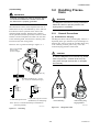
(12) Grounding
3.2 Handling Precautions
IMPORTANT
Improper grounding can have an adverse affect
on the flow measurement. Please ensure that
the instrument is properly grounded.
WARNING
The Magnetic Flow tube is a heavy instrument.
Please be careful to prevent persons from
injuring when it is handled.
The electromotive force of the magnetic flow tube is
minute and it is easy to be affected by noise. And also
that reference electric potential is the same as the
measuring fluid potential. Therefore, the reference
electric potential (terminal potential) of the Flow Tube
and the Converter/Amplifier also need to be the same
as the measuring fluid. And moreover, that the potential must be the same with ground.
3.2.1
General Precautions
(1) Precaution for Carrying
The Magnetic Flow Tube is packed tightly. When it is
unpacked, please give attention to prevent damages to
the flow tube. And to prevent the accident during carry
to the installing location, please carry it near the
location keeping packed as it delivered.
Please be sure to ground according to Figure 3.1.7.
600 V vinyl insulated
electric cable
(2 mm2 or larger)
CAUTION
In case the Magnetic Flow Tube lifts up, please
refer to Figure 3.2.1. Please never lift up by
using a bar through the flow tube. It damages
liner severely.
Earth ring
Grounding resistance 100 Ω or less
(10 Ω or less for JIS flameproof type)
In case earth rings are used.
In case earth rings are not used.
(Available only for metal piping)
Horizontal Lifting
Note; See "3.4.1 Protective Grounding" for information on
protective grounding.
Vertical Lifting Sling
Rigging Method
F030201.EPS
F030107.EPS
Figure 3.1.7
Figure 3.2.1
Grounding
3-3
Lifting Flow Tubes
IM 1E6D0-01E
3. INSTALLATION
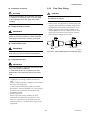
3.2.2
(2) Precaution for Shock
CAUTION
Flow Tube Piping
CAUTION
Care should be taken not to drop the flow tube
or subject it to excessive shock. This may lead
to liner damage which will cause inaccurate
readings.
Mis-aligned or slanted piping can lead to leakage
and damage to flanges.
• Please correct mis-alignment or slanted piping and
improper distance between mounting flanges before
install the flow tube. (Please refer to Figure 3.2.2)
• Inside a pipeline which is newly installed, some
foreign substances (such as welding scrap or wood
chips) may exist. Please remove them by flushing
piping before mounting the flow tube.
(3) Flange Protection Covers
IMPORTANT
Please keep the protection cover (ex. corrugated
paper or anything possible to protect) attached
with flange except when mounting to the pipe.
(4) Terminal Box Cover
Slant
IMPORTANT
Mis-alignment
F030202.EPS
Please never leave the terminal box cover open
until wiring to prevent insulation deterioration.
Figure 3.2.2
Slant and Mis-alignment of Flow Tube Piping
(5) Long-term Non-use
IMPORTANT
It is not preferable to leave the flow tube for long
term non-use after installation.
In case the flow tube is compelled to do that,
please take care of the flow tube by the followings.
• Confirmation of Sealing Condition for the Flow
Tube
Please confirm the sealing conditions of the terminal
box screw and wiring ports.
In case of the Conduit Piping, please provide the
drain plugs or waterproof glands to it to prevent that
moisture or water penetrates into the flow tube
through the conduit.
• Regular Inspections
Please inspect the sealing condition (as above
mentioned) and inside of the terminal box. And
when it is suspect that water penetration into the
inside flow tube (ex. rain fall), please inspect when
it happened.
3-4
IM 1E6D0-01E
3. INSTALLATION
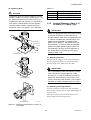
(1) Mounting Direction
Please mount the Magnetic Flow Tube matching the
flow direction of the fluid to be measured with the
direction of the arrow mark on the flow tube.
3.3 Mounting
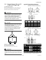
3.3.1
Nominal Diameter 2.5 mm (0.1˝)
to 10 mm (0.4˝) Union Joint
Type
IMPORTANT
NOTE
If it is impossible to match the direction, please
never remodel by changing direction of the
terminal box. In case the measuring fluid flows
against the arrow direction, please refer to the
section “Reversing Flow Direction” in the Instruction Manual of AM11 Magnetic Flow Converter.
Please ensure to use the attached connecting
fittings.
Ceramic linings with a diameter of 2.5, 5 or 10 mm are
connected using union joints.
Use the connecting fittings according to the table
below. Depending on whether the fitting is to be
welded to or screwed on to the piping.
Table 3.3.1
(2) Connecting Process Piping
Weld or screw the connecting fittings to the process
piping.
Fitting Dimensions
Screw joint (Code: U2, U3)
D
ØB ØC –0.1
11.5(0.4")
30(1.2")
4
(0.16")
Size
Code
mm(inch)
5(0.2)
10(0.4)
• Please be sure to pass the connecting fittings
through the union joint nuts in advance. Then
connect the connecting fitting to the piping by
screwing or welding the connecting fitting to the
piping (see Figure 3.3.1).
• In case of weld joint type, please pay attention
the welding condition to avoid deforming piping
or making the stagnant portion of the fluid;
joint preparation, level defference in butt joint,
welding current.
0
ØA
2.5(0.1)
IMPORTANT
A
B
C
D
U2
22(0.87")
8(0.31")
18.5(0.73")
R1/4(PT1/4)
U3
22(0.87")
8(0.31")
18.5(0.73")
NPT1/4
U2
22(0.87")
8(0.31")
18.5(0.73")
R1/4(PT1/4)
U3
22(0.87")
8(0.31")
18.5(0.73")
NPT1/4
U2
25(0.98") 10(0.39")
22.5(0.89")
R3/8(PT3/8)
U3
25(0.98") 10(0.39")
22.5(0.89")
NPT3/8
(3) Positioning the Flow Tube
Install the magnetic flow tube on a mounting base and
position it so that the center axis of the flow tube is
aligned with that of the piping. Then mount the flow
tube to union joint nuts by screwing the nuts to the
connecting ports of the flow tube.
Weld joint (Code: U1)
0.3
ØA ØB
0
ØC 0 ØD –0.1
10(0.39")
4
(0.16")
CAUTION
35(1.38")
Size
Code
mm(inch)
A
B
C
D
2.5(0.1)
U1
22(0.87")
8(0.31")
14.3(0.56")
18.5(0.73")
5(0.2)
U1
22(0.87")
8(0.31")
14.3(0.56")
18.5(0.73")
10(0.4)
U1
25(0.98") 10(0.39")
17.8(0.70")
22.5(0.89")
The ceramic pipe will be damaged if they are
tightened when they are not properly aligned.
T030301.EPS
3-5
IM 1E6D0-01E
3. INSTALLATION
(4) Tightening Nuts
Table 3.3.2
Size: mm(inch) Tightening Torque N-m {kgf-cm} [in-lbf]
CAUTION
Tighten the union joint nuts according to Torque
Values in Table 3.3.1 using a torque wrench. As
the gasket material is Fluorocarbon PTFE, it is
possible that nuts may loose by it’s character as
time passes. Please tighten the nuts regularly.
The table below shows the tightening torque
values. Be sure to use gasket : t=1.5 attached.
2.5(0.1)
Max.12{122}[106]
5(0.2)
Max.12{122}[106]
10(0.4)
Max.18{183}[160]
T030302.EPS
3.3.2
Nominal Diameter 2.5mm (0.1˝)
to 40mm (1.5˝) Wafer Type
IMPORTANT
Please use appropriate bolts and nuts according
to process connection. In case stud type of
through bolts are used, be sure outside diameter
of a shank is smaller than a thread ridge’s one.
Please use compressed non-asbestos fiber
gasket, PTFE gasket or the gasket which has
equal elasticity. In case of optional code/FRG,
please use rubber gasket or others which has
equal elasticity. Be sure the inner diameter of
the gasket does not protrude to inner piping.
(Refer to Table 3.3.8)
Gasket
Connecting fitting
Union joint nut
Piping*
Mounting base*
*: user's scope
(1) Mounting Direction
Please mount the Magnetic Flow Tube matching the
flow direction of the fluid to be measured with the
direction of the arrow mark on the flow tube.
IMPORTANT
If it is impossible to match the direction, please
never remodel by changing direction of the
terminal box. In case the measuring fluid flows
against the arrow direction, please refer to the
section “Reversing Flow Direction” in the Instruction Manual of AM11 Magnetic Flow Converter.
Horizontal Mounting
(2) Mounting Centering Devices
To keep concentricity of the Flow Tube with pipes,
please mount centering devices on the Mini-Flanges of
the Flow Tube.
Please give attention to the nominal diameter and
flange ratings of the centering devices.
Vertical Munting
Figure 3.3.1
F030301.EPS
Mounting Procedure (Size: 2.5 mm(0.1") to
10 mm(0.4"))
3-6
IM 1E6D0-01E
3. INSTALLATION
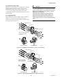
(3) Positioning Flow Tube
Please pass two through-bolts to adjacent holes of both
flanges and mount the Flow Tube, and pass other
through-bolts to other holes. (Refer to Figure 3.3.2/
3.3.3) In case stud type of through-bolts are used,
position them coming in contact centering devices with
thread of bolts.
CAUTION
In case of PFA lining type, as the lining material
is Fluorocarbon PFA, it is possible that nuts may
loose by its character as time passes. Please
tighten the nuts regularly.
Please be sure to tighten the bolts following
prescribed torque values. Please tighten the
flange bolts diagonally with the same torque
values, step by step up to the prescribed torque
value.
(4) Tightening Nuts
Please tighten the bolts according to Torque Values in
Table 3.3.3. In case of PVC piping, please select
optional code /FRG, use rubber gasket and tighten with
the torque value in Table 3.3.4.
Through-bolts (four)
Gasket (two)
Mini-flange
Centering devices (two)
Nuts
Please use appropriate bolts and
nuts according to process
connection.
Flange
Nuts (eight)
Horizontal Mounting
Vertical Mounting
F030302.EPS
Figure 3.3.2 Mounting Procedure (Size: 2.5 mm(0.1") to 15 mm(0.5"))
Through-bolts (four)
Gasket (two)
Mini-flange
Flange
Nuts (eight)
Please use appropriate
bolts and nuts according
to process connection.
Horizontal Mounting
Centering devices (two)
Vertical Mounting
F030303.EPS
Figure 3.3.3 Mounting Procedure (Size: 25 mm(1"), 40 mm(1.5"))
3-7
IM 1E6D0-01E
3. INSTALLATION
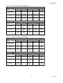
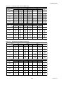
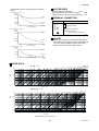
Table 3.3.3
Tightening Torque Values for Metal Piping
Tightening Torque Values for PFA lining / Polyurethane lining Type N-m {kgf-cm} [in-lbf]
Flange
Rating
Size
mm(inch)
JIS
ANSI
DIN
10K
20K
150
300
PN10/16
2.5(0.1), 5(0.2)
10(0.4), 15(0.5)
6 to 9
{61 to 92}
[53 to 80]
6 to 9
{61 to 92}
[53 to 80]
6 to 9
{61 to 92}
[53 to 80]
6 to 9
{61 to 92}
[53 to 80]
6 to 9
{61 to 92}
[53 to 80]
25(1)
15 to 22
{153 to 224}
[133 to 195]
15 to 22
{153 to 224}
[133 to 195]
12 to 18
{122 to 184}
[106 to 159]
15 to 22
{153 to 224}
[133 to 195]
11 to 17
{112 to 173}
[97 to 150]
40(1.5)
21 to 32
{214 to 327}
[186 to 283]
21 to 32
{214 to 327}
[186 to 283]
17 to 26
{173 to 265}
[150 to 230]
25 to 38
{255 to 388}
[221 to 336]
21 to 32
{214 to 327}
[186 to 283]
Maximum Tightening Torque Values for Ceramic lining Type N-m {kgf-cm} [in-lbf]
Flange
Rating
Size
mm(inch)
JIS
10K
15(0.5)
25(1)
40(1.5)
14
{143}
[124]
30
{306}
[265]
44
{449}
[389]
ANSI
DIN
20K
14
{143}
[124]
150
300
PN10/16
14
{143}
[124]
14
{143}
[124]
14
{143}
[124]
30
{306}
[265]
22
{224}
[195]
30
{306}
[265]
25
{255}
[221]
44
{449}
[389]
33
{337}
[292]
51
{520}
[451]
50
{510}
[442]
*Please use compressed non-asbestos fiber gasket, PTFE gasket or the gasket which has equal elasticity.
T030303.EPS
Table 3.3.4
Tightening Torque Values for PVC Piping
Tightening Torque Values for PFA lining / Polyurethane lining Type N-m {kgf-cm} [in-lbf]
Size
mm(inch)
Flange
Rating
ANSI
JIS
DIN
20K
150
300
PN10/16
2.5(0.1), 5(0.2)
10(0.4), 15(0.5)
2.0
{20}
[18]
—
2.1
{21}
[19]
—
2.0
{20}
[18]
25(1)
5.2
{53}
[46]
—
4.2
{43}
[37]
—
4.0
{41}
[35]
40(1.5)
7.4
{76}
[65]
—
6.0
{61}
[53]
—
7.4
{76}
[65]
10K
Maximum Tightening Torque Values for Ceramic Type N-m {kgf-cm} [in-lbf]
Size
mm(inch)
Flange
Rating
JIS
DIN
ANSI
150
300
PN10/16
—
1.3
{13}
[12]
—
1.3
{13}
[12]
3.5
{36}
[31]
—
2.8
{29}
[25]
—
2.7
{28}
[24]
5.7
{58}
[50]
—
4.6
{47}
[41]
—
5.7
{58}
[50]
10K
20K
15(0.5)
1.3
{13}
[12]
25(1)
40(1.5)
*Please select optional code/FRG and use rubber gasket or others which has equal elasticity.
T030304.EPS
3-8
IM 1E6D0-01E
3. INSTALLATION
3.3.3
Nominal Diameter 50 mm(2˝) to
200 mm(8˝) Wafer Type
NOTE
When installing a size 150mm with JIS F12
(JIS75M) flange, please displace in circumferential direction slightly because the cover of
electrode chamber will interfere against the bolts.
IMPORTANT
Please use appropriate bolts and nuts according
to process connection. In case stud type of
through bolts are used, be sure outside diameter
of a shank is smaller than a thread ridge’s one.
Please use compressed non-asbestos fiber
gasket, PTFE gasket or the gasket which has
equal elasticity. In case of optional code/FRG,
please use rubber gasket or others which has
equal elasticity. Be sure the inner diameter of
the gasket does not protrude to inner piping.
(Refer to Table 3.3.8)
(4) Tightening Nuts
Please tighten the bolts according to Torque Values in
Table 3.3.5. In case of PVC piping, please select
optional code/FRG, use rubber gasket and tighten with
the torque value in Table 3.3.6.
CAUTION
In case of PFA lining type as the lining material
is Fluorocarbon PFA, it is possible that nuts
loose by its character as time passes. Please
tighten the nuts regularly.
Please be sure to tighten the bolts following
prescribed torque values. Please tighten the
flange bolts diagonally with the same torque
values, step by step up to the prescribed torque
value.
(1) Mounting Direction
Please mount the Magnetic Flow Tube matching the
flow direction of the fluid to be measured with the
direction of the arrow mark on the flow tube.
IMPORTANT
If it is impossible to match the direction, please
never remodel to change direction of the terminal box. In case the measuring fluid flows
against the arrow direction, please refer to the
section “Reversing Flow Direction” in the Instruction Manual of AM11 Magnetic Flow Converter.
Through bolts
Gaskets (two)
Flanges
Nuts
Please use appropriate
bolts and nuts
according to Process
connection.
(2) Mounting Centering Devices
To keep concentricity between the Flow Tube and
pipes, centering devices must be used. Pass two
through-bolts through the four centering devices (two
for each) and lower adjacent holes of both flanges.
(Refer to Figure 3.3.4)
Housing
Mini-Flange
Centering devices (four)
Please give attention to the nominal size and flange
ratings of the centering devices. (Refer to Table 3.3.7)
(3) Positioning Flow Tube
Position the Flow Tube coming in contact four centering devices with Mini-Flanges. At this time, pay
attention to avoid four centering devices come in
contact with Housing. In case stud type of throughbolts are used, position them coming in contact four
centering devices with thread of the bolts. (Refer to
Figure 3.3.4) After positioning the Flow Tube, pass
remaining through-bolts to remaining holes.
Horizontal Mounting
Vertical Mounting
F030304.EPS
Figure 3.3.4
3-9
Mounting Procedure
IM 1E6D0-01E
3. INSTALLATION
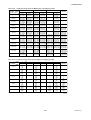
Table 3.3.5
Tightening Torque Values for Metal Piping
Tightening Torque Values for PFA lining / Polyurethane lining Type N-m {kgf-cm} [in-lbf]
Size
mm(inch)
Flange
Rating
JIS
ANSI
DIN
PN16
JIS G3451
F12
14 to 21
{143 to 214}
[124 to 186]
25 to 37
{255 to 378}
[221 to 327]
28 to 42
{286 to 429}
[248 to 372]
21 to 31
{214 to 316}
[186 to 274]
41 to 62
{418 to 633}
[363 to 549]
35 to 51
{357 to 520}
[310 to 451]
41 to 61
{418 to 622}
[363 to 540]
35 to 52
{357 to 531}
[310 to 460]
68 to 102
{694 to 1041}
[602 to 903]
43 to 68
{439 to 694}
[381 to 602]
63 to 89
{643 to 908}
[558 to 788]
41 to 60
{418 to 612}
[363 to 531]
65 to 94
{663 to 959}
[575 to 832]
65 to 94
{663 to 959}
[575 to 832]
68 to 100
{694 to 1020}
[602 to 885]
61 to 92
{622 to 939}
[540 to 814]
93 to 120
{949 to 1224}
[823 to 1062]
65 to 93
{663 to 949}
[575 to 823]
94 to 125
{959 to 1276}
[832 to 1106]
58 to 84
{592 to 857}
[513 to 743]
69 to 101
{704 to 1031}
[611 to 894]
10K
20K
150
300
28 to 42
{286 to 429}
[248 to 372]
21 to 31
{214 to 316}
[186 to 274]
14 to 21
{143 to 214}
[124 to 186]
26 to 39
{265 to 398}
[230 to 345]
28 to 42
{286 to 429}
[248 to 372]
41 to 61
{418 to 622}
[363 to 540]
100(4)
35 to 51
{357 to 520}
[310 to 451]
43 to 64
{439 to 653}
[381 to 566]
150(6)
65 to 94
{663 to 959}
[575 to 832]
200(8)
57 to 84
{582 to 857}
[504 to 743]
50(2)
80(3)
PN10
Maximum Tightening Torque Values for Ceramic lining Type N-m {kgf-cm} [in-lbf]
Size
mm(inch)
Flange
Rating
JIS
ANSI
DIN PN
JIS G3451
F12
10K
20K
150
300
PN10
PN16
50(2)
50
{510}
[442]
27
{276}
[239]
50
{510}
[442]
27
{276}
[239]
—
63
{643}
[558]
80(3)
36
{367}
[319]
44
{449}
[389]
75
{765}
[664]
44
{449}
[389]
—
36
{367}
[319]
80
{816}
[708]
100(4)
48
{490}
[425]
58
{592}
[513]
49
{500}
[434]
56
{571}
[496]
—
48
{490}
[425]
105
{1071}
[929]
150(6)
79
{806}
[699]
55
{561}
[487]
66
{673}
[584]
43
{439}
[381]
—
76
{776}
[673]
84
{857}
[743]
200(8)
70
{714}
[619]
76
{776}
[673]
102
{1041}
[903]
76
{776}
[673]
103
{1051}
[911]
67
{684}
[593]
102
{1041}
[903]
*Please use compressed non-asbestos fiber gasket, PTFE gasket or the gasket which has equal elasticity.
T030305.EPS
Table 3.3.6
Tightening Torque Values for PVC Piping
Tightening Torque Values for PFA lining / Polyurethane lining Type N-m {kgf-cm} [in-lbf]
Size
mm(inch)
Flange
Rating
JIS
ANSI
DIN
JIS G3451
F12(75M)
10K
20K
150
300
PN10
PN16
50(2)
9.8
{100}
[87]
—
9.8
{100}
[87]
—
—
9.8
{100}
[87]
—
80(3)
7.2
{73}
[64]
—
14.4
{147}
[127]
—
—
7.2
{73}
[64]
14.4
{147}
[127]
100(4)
12.2
{124}
[108]
—
12.2
{124}
[108]
—
—
12.2
{124}
[108]
24.4
{249}
[216]
150(6)
21.4
{218}
[189]
—
20.5
{209}
[181]
—
21.4
{218}
[189]
21.4
{218}
[189]
23.4
{239}
[207]
200(8)
19.3
{197}
[171]
—
27.6
{282}
[244]
—
28.9
{295}
[256]
19.3
{197}
[171]
31.6
{322}
[280]
PN16
JIS G3451
F12(75M)
Maximum Tightening Torque Values for Ceramic lining Type N-m {kgf-cm} [in-lbf]
Size
mm(inch)
50(2)
80(3)
Flange
Rating
JIS
10K
8.2
{84}
[73]
6.2
{63}
[55]
ANSI
20K
—
—
150
8.2
{84}
[73]
12.4
{127}
[110]
DIN
300
PN10
—
—
—
—
8.2
{84}
[73]
6.2
{63}
[55]
12.3
{126}
[109]
—
100(4)
8.0
{82}
[71]
—
8.1
{83}
[72]
—
—
8.0
{82}
[71]
16.1
{164}
[142]
150(6)
19.8
{202}
[175]
—
18.9
{193}
[167]
—
19.8
{202}
[175]
19.8
{202}
[175]
21.6
{220}
[191]
200(8)
17.5
{179}
[155]
—
25.1
{256}
[222]
—
26.2
{267}
[232]
17.5
{179}
[155]
28.7
{293}
[254]
*Please select optional code/FRG and use rubber or gasket or others which has equal elasticity.
3-10
T030306.EPS
IM 1E6D0-01E
3. INSTALLATION
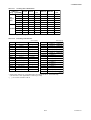
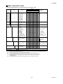
Table 3.3.7
Centering Device Identification
Flange Rating
Lining
PFA,
polyurethane
Ceramics
JIS G3451
ANSI 150
F12
ANSI 300
DIN PN
10/16
JIS 10K
JIS 20K
50(2)
B
B
—
B
F
F
80(3)
B
F
H
F
C
G
mm(inch)
100(4)
B
F
H
C
H
F
150(6)
C
D
D
C
E
C
200(8)
C
D
D
D
E
C
50(2)
B
B
—
B
F
F
80(3)
B
F
H
F
C
G
100(4)
B
F
H
C
H
F
150(6)
B
C
G
B
D
B
200(8)
B
C
C
G
J
B
*Each Centering Devices is engraved a character as identifidation.
Table 3.3.8
T030307.EPS
Earth Ring inside diameter
Unit: mm(inch)
Size
2.5(0.1)
5(0.2)
PFA/Polyurethane lining
φ15(0.6)
φ15(0.6)
Ceramic lining
—
—
Unit: mm(inch)
Size
Polyurethane lining
500(20)
φ468(18.4)
[φ485(19.1)]
600(24)
φ563(22.2)
[φ589(23.9)]
[φ689(27.1)]
10(1.4)
φ15(0.6)
—
700(28)
φ665(26.2)
15(0.5)
φ15(0.6)
φ15(0.6)
800(32)
φ765(30.1)
[φ788(31.0)]
25(1)
φ27(1.1)
φ27(1.1)
900(36)
φ855(33.7)
[φ888(35.0)]
40(1.5)
φ40(1.6)
φ40(1.6)
1000(40)
φ942(37.1)
[φ990(39.0)]
50(2)
φ52(2.1)
φ52(2.1)
1100(44)
φ1085(42.7)
80(3)
φ81(3.2)
φ81(3.2)
1200(48)
φ1185(46.7)
100(4)
φ98(3.9)
φ98(3.9)
1350(54)
φ1335(52.6)
150(6)
φ140.7(5.6)
φ144(5.7)
1500(60)
φ1485(58.5)
200(8)
φ188.9(7.5)
φ192(7.6)
1600(64)
φ1585(62.4)
250(10)
φ239.1(9.5)
—
1800(72)
φ1785(70.3)
300(12)
φ291.3(11.5)
—
2000(80)
φ1985(78.1)
350(14)
φ323.4(12.8)
—
2200(88)
φ2185(86)
400(16)
φ373.5(14.8)
—
2400(96)
φ2385(93.9)
2600(104)
φ2585(101.8)
T030308.EPS
* Please ensure that the I.D. of the gasket does not protrude into the I.D. of the Earth Ring.
(This dimension is also applied when no earth ring is used)
* [ ] ; for Process connection code G1
3-11
IM 1E6D0-01E
3. INSTALLATION
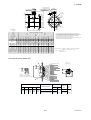
3.3.4
Nominal Diameter 15 mm (0.5˝)
to 400 mm (16˝) Flange Type
(2) Tightening Nuts
Please tighten the bolts according to Torque Values in
Table 3.3.9. In case of PVC piping, please select
optional code/FRG, use rubber gasket and tighten with
the torque value in Table 3.3.10.
IMPORTANT
Please use appropriate bolts and nuts according
to process connection. Please use compressed
non-asbestos fiber gasket, PTFE gasket or the
gasket which has equal elasticity. In case of
optional code/FRG, please use rubber gasket or
others which has equal elasticity. Be sure the
inner diameter of the gasket does not protrude to
inner piping.(Refer to Table 3.3.8)
CAUTION
In case of PFA lining type as the lining material
is Fluorocarbon PFA, it is possible that bolts
loose by its character as time passes. Please
tighten the nuts regularly.
Please be sure to tighten the bolts following
prescribed torque values. Please tighten the
flange bolts diagonally with the same torque
values, step by step up to the prescribed torque
value.
(1) Mounting Direction
Please mount the Magnetic Flow Tube matching the
flow direction of the fluid to be measured with the
direction of the arrow mark on the flow tube.
IMPORTANT
If it is impossible to match the direction, please
never remodel to change direction of the terminal box. In case the measuring fluid flows
against the arrow direction, please refer to the
section “Reversing Flow Direction” in the Instruction Manual of AM11 Magnetic Flow Converter.
Gasket (two)
Flange (Flow tube)
Bolts
Please use appropriate bolts and
nuts according to process
conneciton.
Nuts
Flange
(Piping side)
F030305.EPS
Figure 3.3.5 Mounting Procedure (Size: 15 mm (0.5") to 400 mm (16"))
3-12
IM 1E6D0-01E
3. INSTALLATION
Table 3.3.9
Size
mm(inch)
Tightening Torque Values for Metal Piping in N-m{kgf-cm} [in-lbf]
Flange
Rating
JIS
ANSI
DIN
JIS G3451
F12(75M)
10K
20K
150
300
PN10
3 to 5
{31 to 51}
[27 to 44]
3 to 5
{31 to 51}
[27 to 44]
3 to 5
{31 to 51}
[27 to 44]
—
8 to 13
{82 to 133}
[71 to 115]
18 to 26
{184 to 265}
[159 to 230]
8 to 13
{82 to 133}
[71 to 115]
18 to 26
{184 to 265}
[159 to 230]
3 to 5
{31 to 51}
[27 to 44]
6 to 10
{61 to 102}
[53 to 88]
8 to 13
{82 to 133}
[71 to 115]
—
15 to 21
{153 to 214}
[133 to 186]
21 to 31
{214 to 316}
[186 to 274]
—
18 to 26
{184 to 265}
[159 to 230]
—
50(2mm)
22 to 31
{224 to 316}
[195 to 274]
11 to16
{112 to 163}
[97 to 142]
23 to 31
{235 to 316}
[204 to 274]
11 to 16
{112 to 163}
[97 to 142]
—
23 to 31
{235 to 316}
[204 to 274]
—
80(3mm)
15 to 22
{153 to 224}
[133 to 195]
18 to 27
{184 to 276}
[159 to 239]
35 to 43
{357 to 439}
[310 to 381]
18 to 26
{184 to 265}
[159 to 230]
—
16 to 22
{163 to 224}
[142 to 195]
33 to 47
{337 to 480}
[292 to 416]
100(4mm)
21 to 35
{214 to 357}
[186 to 310]
25 to 44
{255 to 449}
[221 to 389]
22 to 35
{224 to 357}
[195 to 310]
25 to 42
{255 to 429}
[221 to 372]
—
21 to 35
{214 to 357}
[186 to 310]
47 to 75
{480 to 765}
[416 to 664]
150(6mm)
65 to 94
{663 to 959}
[575 to 832]
43 to 68
{439 to 694}
[381 to 602]
63 to 89
{643 to 908}
[558 to 788]
41 to 59
{418 to 602}
[363 to 522]
65 to 94
{663 to 959}
[575 to 832]
65 to 94
{663 to 959}
[575 to 832]
65 to 100
{663 to 1020}
[575 to 885]
57 to 84
{582 to 857}
[504 to 743]
61 to 92
{622 to 939}
[540 to 814]
93 to 120
{949 to 1224}
[823 to 1062]
65 to 93
{663 to 949}
[575 to 823]
15(0.5mm)
25(1mm)
40(1.5mm)
PN16
3 to 5
{31 to 51}
[27 to 44]
6 to 10
{61 to 102}
[53 to 88]
250(10mm)
155 to 199
114 to 138
125 to 145
164 to 187
154 to 180
190 to 249
175 to 213
{1163 to 1408} {1276 to 1480} {1673 to 1908} {1571 to 1837} {1582 to 2031} {1786 to 2173} {1939 to 2541}
[1009 to 1221] [1106 to 1283] [1451 to 1655] [1363 to 1593] [1372 to 1761] [1549 to 1885] [1681 to 2204]
300(12mm)
350(14mm)
400(16mm)
158 to 183
{1612 to 1867}
[1398 to 1619]
—
245 to 284
{2500 to 2898}
[2168 to 2513]
—
152 to 192
{1551 to 1959}
[1345 to 1699]
—
274 to 325
{2796 to 3316}
[2425 to 2876]
243 to 261
{2480 to 2663}
[2150 to 2310]
—
253 to 275
{2582 to 2806}
[2239 to 2434]
—
248 to 331
{2531 to 3378}
[2195 to 2929]
—
313 to 395
{3194 to 4031}
[2770 to 3496]
*Please use compressed non-asbestos fiber gasket, PTFE gasket or the gasket which has equal elasticity.
Size
mm(inch)
15(0.5)
25(1)
40(1.5)
50(2)
80(3)
100(4)
150(6)
200(8)
—
58 to 84
69 to 101
94 to 125
{959 to 1276} {592 to 857} {704 to 1031}
[513 to 743]
[611 to 894]
[832 to 1106]
142 to 174
154 to 182
145 to 177
126 to 151
154 to 175
215 to 270
136 to 164
{1449 to 1776} {1571 to 1857} {1480 to 1806} {1286 to 1541} {1388 to 1673} {1571 to 1786} {2194 to 2755}
[1257 to 1540] [1363 to 1611] [1283 to 1566] [1115 to 1336] [1204 to 1451] [1363 to 1549] [1903 to 2389]
200(8mm)
Table 3.3.10
—
T030309.EPS
Tightening Torque Values for PVC Piping in N-m{kgf-cm} [in-lbf]
Flange
Rating
JIS
10K
1.1
{11}
[10]
2.9
{30}
[26]
5.9
{60}
[52]
7.2
{73}
[64]
4.9
{50}
[43]
8.1
{83}
[72]
29.8
{304}
[264]
26.3
{268}
[233]
ANSI
20K
—
—
—
—
—
—
—
—
150
1.1
{11}
[10]
2.3
{23}
[20]
4.7
{48}
[42]
7.2
{73}
[64]
9.9
{101}
[88]
8.2
{84}
[73]
28.5
{291}
[252]
37.7
{385}
[334]
DIN
300
PN10
—
—
—
—
—
—
—
—
—
—
—
—
—
29.8
{304}
[264]
8.1
{83}
[72]
29.8
{304}
[264]
—
39.4
{4,2}
[349]
26.3
{268}
[233]
*Please select optional code/FRG and use rubber or gasket or others which has equal elasticity.
3-13
PN16
1.1
{11}
[10]
2.2
{22}
[19]
5.9
{60}
[52]
7.2
{73}
[64]
4.9
{50}
[43]
JIS G3451
F12(75M)
—
—
—
—
9.9
{101}
[88]
16.3
{166}
[144]
32.6
{33}
[288]
43.1
{440}
[381]
T030310.EPS
IM 1E6D0-01E
3. INSTALLATION
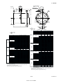
3.3.5
(3) Installation Foundation Dimensions
Mominal Diameter 500 mm (20")
to 2600 (104") Flange Type
Table 3.3.11
Installation Foundation Dimensions
[Nominal Dia. 500 mm (20") to 1000 mm (40")]
(1) Mounting Direction
Please mount the Magnetic Flow Tube matching the
flow direction of the fluid to be measured with the
direction of the arrow mark on the flow tube.
150*
(5.9)
IMPORTANT
If it is impossible to macth the direction, please
never remodel to change direction of the terminal box. In case the measuring fluid flows
against the arrow direction, please refer to the
section “Reversing Flow Direction” in the Instruction Manual of AM11 Magnetic Converter.
4-Anchor bolt
CAUTION
When lifting the flow tube, please use the lifting
rings (eye bolts or shackle).
To assure safety, please keep lifting angle less
than 90 degrees as shown in Figure 3.3.6.
Please do not shock the installation foundation
bracket when installing the flowmeter as the
bracket may be damaged.
Size:
mm (inch)
A
B
C
D
500 (20)
600 (24)
700 (28)
800 (32)
900 (36)
1000 (40)
350 (13.8)
400 (15.7)
450 (17.7)
550 (21.7)
700 (27.6)
800 (31.5)
350 (13.8)
400 (15.7)
500 (19.7)
550 (21.7)
650 (25.6)
700 (27.6)
420 (16.5)
470 (18.5)
570 (22.4)
620 (24.4)
770 (30.3)
870 (34.3)
125 (4.9)
125 (4.9)
125 (4.9)
125 (4.9)
125 (4.9)
125 (4.9)
T030311.EPS
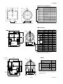
Table 3.3.12 Installation Foundation Dimensions
[Nominal Dia. 1100 mm (44") to 2600 mm (104")]
F*
500 (19.7)
90° or less
A
16-T
D
D
G
G
H
I
K
J
C
H
L
F030306.EPS
Figure 3.3.6 Lifting Flow Tube
Size:
mm (inch)
(2) Positioning Flow Tube
Please position the flow tube using a jack.
1,100 (44)
1,200 (48)
1,350 (54)
1,500 (60)
1,600 (64)
1,800 (72)
2,000 (80)
2,200 (88)
2,400 (96)
2,600 (104)
IMPORTANT
Please apply the jack to near the flow tube
support and insert a steel liner between the
bracket and flow tube support. Never use wooden
liner.
A
1,211 (47.7)
1,261 (49.6)
1,366 (53.8)
1,490 (58.7)
1,698 (66.9)
1,864 (73.4)
2,010 (79.1)
2,172 (85.5)
2,218 (87.3)
2,300 (90.6)
C
1,500 (59.1)
1,600 (63.0)
1,750 (68.9)
1,900 (74.8)
2,100 (82.7)
2,250 (88.6)
2,450 (96.5)
2,700 (106.3)
2,900 (114.2)
D
L
(F)
600 200*
(23.6) (7.9)
700 250*
(27.6) (9.8)
Dimensions
G
H
I
J
450 (17.7) 520 (20.5) 1,100 (43.3)
400 500 (19.7) 540 (21.3) 1,200 (47.2)
(15.7) 550 (21.7) 640 (25.2) 1,350 (53.1)
600 (23.6) 700 (27.6) 1,500 (59.1)
650 (25.6) 700 (27.6) 1,650 (65.0)
500 700 (27.6) 750 (29.5) 1,800 (70.9)
(19.7) 700 (27.6) 1,070 (42.1) 2,000 (78.7)
730 (28.7) 1,200 (47.2) 2,200 (86.6)
770 (30.3) 1,330 (52.4) 2,400 (94.5)
2,600 (102.4)
T030312ilust.EPS
K
720 (28.3)
780 (30.7)
880 (34.6)
980 (38.6)
1,080 (42.5)
1,180 (46.5)
1,300 (51.2)
1,430 (56.3)
1,560 (61.4)
1,700 (66.9)
L
T
130
M16*
(5.1)
170
(6.7)
M20*
200
(7.9)
T030312.EPS
Note 1: See the external dimensions for the support dimensions.
Note 2: The value marked as * is reference dimensions.
3-14
IM 1E6D0-01E
3. INSTALLATION
(4) Connecting to Pipe
Please pass bolts from pipe line side, not flow tube
side, and tighten the bolts according to Torque Values
in Table 3.3.9.
IMPORTANT
If it is impossible to macth the direction, please
never remodel to change direction of the terminal box. In case the measuring fluid flows
against the arrow direction, please refer to the
section “Reversing Flow Direction” in the Instruction Manual of AM11 Magnetic Converter.
CAUTION
• Please be sure to tighten the bolts following
prescribed torque values. Please tighten the
flange bolts diagonally with the same torque
values, step by step up to the prescribed torque
value.
• Please completely cover the brackets and liners
with mortar.
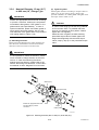
(2) Welding of Mating Ferrule to Piping
IMPORTANT
Weld the attached ferrules to the piping. Please
pay attention to the welding condition to avoid
deforming piping or making the stagnant portion
of the fluid; joint preparation, level difference in
butt joint, welding current.
(3) Mounting Gasket
Mount the attached gasket so it fits into the groove on
the ferrule.
Figure 3.3.7
Mounting Flow Tube
Table 3.3.13
Tightening Torgue Values for Metal Piping
Flange
Rating
SIze:
mm (inch)
kgf-cm
in-Ibf
N-m
kgf-cm
121
1234
1071
63
643
to 150
to 1530
to 1327
to 79
to 806
1183
1027
78
796
600 (24) 116
to 145
to 1479
to 1283
to 97
to 989
1765
1531
104
1061
700 (28) 173
to 215
to 2193
to 1903
to 130
to 1326
180
1836
1593
115
1173
800 (32)
to 224
to 2285
to 1982
to 144
to 1469
1040
903
175
1785
900 (36) 102
to 127
to 1295
to 1124
to 182
to 1856
2356
2044
204
2081
1000 (40) 231
to 288
to 2938
to 2549
to 254
to 2591
3040
2637
—
—
1100 (44) 298
to 372
to 3794
to 3292
3070
2664
—
—
1200 (48) 301
to 376
to 3835
to 3327
4406
3823
—
—
1350 (54) 432
to 539
to 5498
to 4770
4723
4097
—
—
1500 (60) 463
to 578
to 5896
to 5115
4774
4142
—
—
1600 (64) 468
to 585
to 5967
to 5177
4947
4292
—
—
1800 (72) 485
to 605
to 6171
to 5354
6273
5442
—
—
2000 (80) 615
to 768
to 7834
to 6796
6997
6071
—
—
2200 (88) 686
to 858
to 8752
to 7593
7742
6717
—
—
2400 (96) 759
to 948
to 9670
to 8389
10261
8903
—
—
2600 (104) 1006
to 1257
to 12821 to 11124
* Please use rubber gasket or the gasket which has equal elasticity.
500 (20)
ANSI150
JIS10K
JIS G3451 F12/JIS7.5K
N-m
(4) Positioning Flow Tube
Position the flow tube between the mating ferrule.
in-Ibf
N-m
kgf-cm
558
to 699
690
to 858
920
to 1150
1018
to 1274
1549
to 1611
1805
to 2248
—
59 to 73
602 to 745 522 to 646
in-Ibf
67 to 84
683 to 857 593 to 743
—
—
—
—
—
—
—
—
—
—
—
—
—
—
—
—
—
—
—
—
—
—
—
—
—
—
—
—
—
—
—
—
—
—
—
—
—
—
—
—
—
—
—
—
—
—
—
—
—
—
—
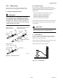
(5) Tightening Clamp
Mount the clamp so they cover the flow tube and
mating ferrule tapered part.
Clamp
Ferrule
T030313.EPS
Pipe
3.3.6
Mounting Procedure for Sanitary Type
Welding
The sanitary type is mounted using IDF clamps.
F030308.EPS
Figure 3.3.8
(1) Mounting Direction
Please mount the Magnetic Flow Tube matching the
flow direction of the fluid to be measured with the
direction of the arrow mark on the flow tube.
3-15
Mounting Procedure
IM 1E6D0-01E
3. INSTALLATION
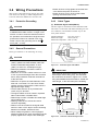
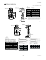
3.4 Wiring Precautions
• Please be sure to fully tighten the terminal box
cover before the power is turned on.
• Please be sure to turn off the power before
opening the terminal box cover.
This section is described wiring only for flow tube
side. Please see "Wiring" in AM11 Magnetic Flow
Converter Instruction Manual for converter side.
3.4.1
Protective Grounding
3.4.3
(1) Dedicated Signal Cable(AM011)
The flow signal is transmitted via this dedicated cable.
The cable is constructed with double shielding over the
two conductors, and used heat-resistant vinyl as the
outer jacket material.
CAUTION
Please be sure to connect protective grounding
of ADMAG with cable of 2mm2 or larger cross
section in order to avoid the electrical shock to
the operators and maintenance engineers and
prevent the influence of external noise. And
further connect the grounding wire to the
mark (100Ω or less).
3.4.2
Cable Types
Finished diameter:
10.5 mm (0.413”)
Maximum length:
200 m (660 ft)
Maximum temperature: 80°C (176°F)
General Precautions
Please give attention to the followings in wiring.
CAUTION
• In case the ambient temperature exceeds 50°C
(122°F), please use heat-resistant cable with
maximum allowable temperature of 70°C
(158°F) or above for JIS flameproof type.
• Please pay attention to avoid the cable is
bended excessively.
• Please do not connect cables outdoors in case
of rain to prevent damages from dew formation
and to keep insulation inside the terminal box
of the flow tube.
• Please do not splice the cable between a flow
tube and a converter if it is too short. Please
replace the short cable with the cable which is
appropriate length wholly.
• The all cable ends are to be provided with
round crimp-on terminal.
• The signal cables must be routed in separate
steel conduit tubes or flexible tubes.
• Please keep conduit or flexible tube water-tight
using sealing tape.
• Please ground each of a flow tube and a
converter separately.
• Please cover each shield of the signal cable
with PVC tube or PVC tape to avoid contacting
between two shields; shield and case.
• When waterproof glands or union equipped
waterproof glands are used, the glands must be
properly tightened to keep the box watertight.
Figure 3.4.1
Dedicated Signal Cable AM011
IMPORTANT
B
30 (1.2)
A
C
90 (3.5)
90 (3.5)
120 (4.7)
(WHITE)
(BLACK)
(RED)
8 (0.3) Max.
(RED)
L (SPECIFIED LENGTH)
20 (0.8)
On the flow tube
side
ø10.5 (0.4)
150
(5.9)
8 (0.3) Max.
On the converter
side
(BLACK)
150
(5.9)
(WHITE)
130 (5.1)
C
70 (2.8)
SB
B
A
SA
30 (1.2)
If the cable is longer than required, cut off any
extra length, rather coiling it up, and terminate
the conductors as shown in Figure 3.4.2. Avoid
using intermediate terminal boards to extend the
cable length, or this will interrupt the shielding.
AM011*A
F030402.EPS
Figure 3.4.2
3-16
Treatment of Dedicated Signal Cable
IM 1E6D0-01E
3. INSTALLATION
3.4.4
CAUTION
Since A, B, SA, SB, and C all operate at different electrical potentials, securely insulate them
from each other so they do not touch.
The shields must not be allowed to touch each
other or to touch the case.
Cover each shield with vinyl tube or wrap in vinyl
tape.
Connnection to AM11Magnetic
Flow Converter
Connect the flow tube and converter in the following
method.
C SA
B
A
SB
EX1
AM11
converter
EX2
Dedicated signal cable
AM011-2
NOTE
Conductors A and B carry the signal from the
electrodes, and C is at the potentials of the liquid
it self (signal common) . Shields SA and SB are
kept at the same potentials as the individual
electrodes (these are actively driven shields).
This is done to reduce the effect of the distributed capacitance of the cable at long cable
length. Note that, since the signals from the
individual electrodes are impedance converted
inside the converter, errors will result if they
come in contact with any other component.
Great care must be taken in the cable end
treatment.
A
EX2
B
EX1
Converter
Terminal
Flow tube
SA
A
B
(See Note below)
A
B
(See Note below)
SB
C
EX1
EX2
C
EX1
EX2
Note: Terminate those shielding wire terminal
using insulating tape.
C
Flow tube
F030404.EPS
Figure 3.4.4
Connection
(2) Excitation Cable
Please use Polyvinyl chloride insulated and sheathed
control cables (JIS C3401) or Polyvinyl chloride
insulated and sheathed portable power cables (JIS
C3312) or equivalents.
Outer Diameter
• 6.5 to 12mm in diameter (7.5 to 12 mm for waterproof gland / ECG, /ECU, /ECW)
Nominal Cross Section
• Single wire; 0.5 to 2.5mm2 , Stranded wire; 0.5 to
2.5mm2
85
(3.3)
On the converter side
EX2
EX1
EX2
EX1
Unit: mm (inch)
85
(3.3)
On the flow tube side
F030403.EPS
Figure 3.4.3
End Treatment of Excitation Cable
3-17
IM 1E6D0-01E
3. INSTALLATION
3.4.5
Wiring Ports
B : Insulation Check
After wiring is completed, check insulation of the
following terminals together with the wiring under the
condition of the converter side wiring terminals
disconnected.
Please select the most suitable standard of wiring
procedure for the wiring ports by customer’s own.
A : Using the Waterproof Gland
Between terminal EX1 and terminal A, B, C
Between terminal C and terminal A, B
Between terminal A and terminal B
Between terminal EX1 and ground
Between terminal EX2 and ground
IMPORTANT
To prevent water or condensate from entering
the converter housing, waterproof glands are
recommended. Do not over-tighten the glands or
damage to the cables may result. Tightness of
the gland can be checked by confirming that the
cable is held firmly in place.
Waterproof gland
Optional code : /ECG
All insulation measurements must be performed with a
500V megger. Insulation resistances must be 100MΩ
or more each.
IMPORTANT
Waterproof gland with union joint
Optional code : /ECU
Be sure to disconnect the cables at the terminal
of the converter when checking insulation.
Gasket
G1/2 female
Tightening
gland
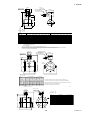
C : Conduit Wiring
In case of conduit wiring, please use the waterproof
gland to prevent water flowing through the conduit
pipe into the wiring connection.
Gasket
Tightening gland
Please slope the conduit pipe down, and install a drain
valve at the low end of the vertical pipe.
G1/2 female
Please open the drain valve regularly.
Waterproof gland
Optional code : /ECW
Gasket
Tightening
gland G3/4
G1/2 female
F030406.EPS
Figure 3.4.6
Waterproof Gland
Drain valve
F030407.EPS
Figure 3.4.7
3-18
Conduit Wiring
IM 1E6D0-01E
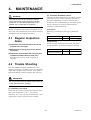
4. MAINTENANCE
4.
MAINTENANCE
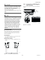
(2) Insulation Resistance Check
Check the insulation resistances in accordance with the
tables below. If one of them falls below the value in
the tables, replacement or repair of the flow tube is
needed. In case of submersible type flowmeter, release
wiring connection of converter side and measure
resistance at cable terminations.
WARNING
This instrument must be repaired or maintenance-serviced by expert engineer or skilled
personnel. The procedures described in this
chapter are not permitted for operators.
Regular maintenance and inspection should be carried
out to fully utilize all functions and to obtain maximum
performance from the magnetic flowmeter.
Coil Circuit
Checking is possible even if the pipe is filled with
fluid.
4.1 Regular Inspection
Items
Test Terminals
Test Voltage
Specification
Between Terminals EX1 and C
500 V DC
1MΩ or more
T0401.EPS
Signal Circuit
Be sure to empty and dry the pipe inside, and release
wiring connection of converter side before checking.
(1)Inspection of moisture-proofing inside the
terminal box: Once/year
(2)Refastening of piping joint screws: About
twice/year
(3)Inspection of electrodes and lining (in case
of adhesive and/or abrasive fluid, etc.)
Determine the period of regular inspection as
necessary.
Test Terminals
Test Voltage
Specification
Between Terminals A and C
Between Terminals B and C
500 V DC
100MΩ or more for each
T0402.EPS
4.2 Trouble Shooting
Since the ADMAG magnetic flowmeter has “self
diagnostic functions”, if a failure occurs, it is displayed
on the AM11 magnetic flow converter. Please refer to
Instruction Manual of AM11 magnetic flow converter.
IMPORTANT
Be sure to disconnect the cables at the terminals
of the flow tube when checking.
(1) Excitation Coil Check
Check that the resistance between terminals EX1 and
EX2 in the terminal box is 150 Ω or less with a
multimeter. If it is not, coils may be broken down, and
replacement or repair of the flow tube is needed.
4-1
IM 1E6D0-01E
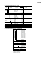
5. OUTLINE
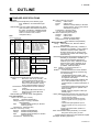
5.
OUTLINE
■ STANDARD SPECIFICATIONS
Size 125 to 400 mm (5 to 16in.)
Housing: Carbon steel
Flange
Carbon steel
Pipe:
Stainless steel (SUS304)*or Alumina
ceramic (99.9%, only for size 150mm
and 200mm (6 and 8in.)
Terminal box : Aluminum alloy.
* For PFA or Polyurethane lining
Size 500 to 2600 mm (20 to 104in.)
Housing: Carbon steel
Flange
Carbon steel
Pipe:
Stainless steel (SUS304)
Terminal box:cover; Aluminum alloy
case; Stainless steel (SUS304)
Wetted Part Material:
Lining: Fluorocarbon PFA, Alumina ceramic,
Polyurethane
Electrode: Stainless steel (SUS316L), Hastelloy C
(equivalent to Hastelloy C-276), Titanium,
Tantalum, Platinum-Iridium, Platinumalumina cermet only for ceramic lining.
*For size over 500mm and sanitary type,
SUS316L only
Earth Ring/Earth Electrode:Stainless steel (SUS316),
Hastelloy C (equivalent to Hastelloy C276), Titanium,SUS304,(Size 500 to
1000mm (20 to 40in.), SS400 lined with
SUS316 (Size 1100 to 2600mm (40 to
104in.) ), PFA lining+Earth electrodes
(Tantalum, Platinum-Iridium).
Protection:
General Purpose /Explosion proof /Sanitary Type:
IP67, NEMA4X, JIS C0920 water tight
type.
Submersible Type: JIS C0920 submersible type, IP68.
(Test Condition: 50m below the surface of
the water, equivalent to 0.5MPa hydraulic
pressure, for one month. If always under
water or corrosion fluid, contact
Yokogawa office.)
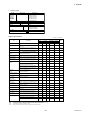
Size:
General Purpose type
Fluorocarbon
PFA
Size in 2.5(0.1), 5(0.2),
mm
10(0.4),15(0.5),
(inch) 25(1), 40(1.5),
50(2), 65(2.5),
80(3), 100(4),
125(5), 150(6),
200(8),250(10),
300(12),350(14),
400(16)
Lining
Ceramic
Polyurethane
2.5(0.1),
5(0.2),
10(0.4),
15(0.5), 25(1),
40(1.5), 50(2),
80(3), 100(4),
150(6), 200(8)
25(1), 40(1.5), 50(2), 80(3), 100(4),
150(6), 200(8), 250(10), 300(12),
350(14), 400(16), 500(20), 600(24),
700(28), 800(32), 900(36),
1000(40),1100(44),1200(48),
1350(54), 1500(60), 1600(64),
1800(72),2000(80), 2200(88 ),
2400(96), 2600(104)
Submersible type
Lining
PFA
25(1),
Size in
40(1.5),
mm
50(2),
(inch)
80(3),
100(4),
150(6),
200(8),
250(10),
300(12),
350(14),
400(16)
Explosion proof type
Polyurethane
Lining
PFA/Ceramic
25(1), 40(1.5), 50(2),
Size in 2.5(0.1), 5(0.2), 10(0.4),
80(3), 100(4), 150(6),
15(0.5),25(1), 40(1.5), 50(2),
mm
200(8), 250(10),
(inch) 80(3), 100(4), 150(6), 200(8)
300(12), 350(14),
400(16),500(20),
Sanitary type*1
600(24), 700(28),
800(32),900(36),
PFA
Lining
1000(40),1100(44),
1200(48), 1350(54),
Size in 25(1), 40(1.5), 50(2),
65(2.5), 80(3),
1500(60),1600(64),
mm
1800(72),2000(80),
(inch) 100(4),
T01.EPS
2200(88),2400(96),
*1: 15, 125mm for Sanitary type flow
2600(104)
tubes are available on request.
Note: Hastelloy is a registered trademark of
Haynes International Inc.
Gasket:
• VALQUA#7020;Fluoro resin with filler
(between flow tube body and earth ring;
for ceramic lining)
• VALQUA#4010;Fluoro rubber, viton
(between flow tube body and earth ring;
for optional code /FRG)
• Non-asbestos joint sheet sheathed with
fluoro resin (between earth ring and
process flange; for optional code /BCF or
/BSC)
• Chloroprene rubber (between earth ring
and process flange; for optional code
/BCC or /BSC)
• EPDM, ethylene propylene rubber (for
sanitary type)
* Other gaskets between flow tube body and earth ring;
Coating:
General Purpose /Explosion Proof /Sanitary Type:
Body:
Size 2.5 to 100 mm (0.1 to 4in.); No
coating (Stainless steel surface)
Size 125mm (5in.) or more; Polyurethane corrosion-resistant coating
Frosty-white (Munsell 2.5Y8.4/1.2)
Terminal box : Polyurethane corrosion-resistant
coating
Case;
Frosty white (Munsell 2.5Y8.4/1.2)
Cover;
Deep sea moss green (Munsell
0.6GY3.1/2.0)
Submersible type: Non-tar epoxy coating(Black)
Flow Tube Material:
Size 2.5 to 15 mm (0.1 to 0.5in.)
Housing:
Stainless steel(SCS11)
Flange (15mm(0.5 in.)only) : Stainless
steel.(SUS304)
Pipe:
Stainless steel (SCS13)*or Alumina
ceramic (99.9%)
Terminal box : Aluminum alloy.
Size 25 to 100 mm (1 to 4in.)
Housing: Stainless steel(SUS304)
Flange :
Stainless steel (SUS304)
Pipe:
Stainless steel (SUS304)*or Alumina
ceramic (99.9%)
Terminal box : Aluminum alloy.
• VALQUA#7026;corrosion resistance gasket
(Fluoro resin with carbon)
• VALQUA#4010(Mixing#RCD970);Alkali
resistance gasket for PVC piping (Fluoro
rubber)
• VALQUA#4010(Mixing#RCD470);Acid
resistance gasket for PVC piping (Fluoro
rubber)
Contact Yokogawa office. (Refer to TI
1E6A0-06E)
Union Joint:Stainless steel (SUS316L), for ceramic
lining size 10mm (0.4in.) or less*
*Contact Yokogwa office if PVC union joints are required.
Ferrule(for sanitary type):SCS13
5-1
IM 1E6D0-01E
5. OUTLINE
■ STANDARD PERFORMANCE
Electrode Construction:
• General Purpose/Ex-proof/Submersible type
PFA, Polyurethane Linings: External Insertion type.
Ceramic Lining: Integral type.
• Sanitary type
Internal Insertion type.
* Only PFA lining is available for sanitary type
Electrical Connection:
JIS G1/2(PF1/2)female, ANSI 1/2NPT female,
DIN Pg13.5 female, ISO M20X1.5 female
Terminal Connection:
M4 size screw terminal.
Grounding:
100Ω or less
* In case of JIS Flameproof type, JIS Class C(10Ω or
less) or JIS Class A(10Ω or less)
Accuracy:
PFA and Ceramic Lining
Vs: Span setting value (m/s)
Size in
mm (inch)
Span in m/s
(ft/s)
Accuracy
0.1 to 0.3(0.3 to 1) 0.15/Vs % of span
0.3 to 1(1 to 3) 0.5% of span
2.5 to 15
(0.1 to 0.5)
0.25% of span (at indications below
1 to 3 (3 to 33) 50%)
(both included)
0.5% of flowrate indication
(at indications 50% of span or more)
0.1 to 0.3(0.3 to 1) 0.075/Vs % of span
0.3 to 1
(1 to 3)
25 to 400
(1 to 16)
■ HAZARDOUS AREA CLASSIFICATION
AM100 / 200DN
0.25% of span
(at indications below 50% of span)
0.5% of flowrate indication
(at indications 50% of span or more)
0.1% of span
(at indications below 20% of span)
1 to 10(3 to 33)
(both included) 0.5% of flowrate indication
(at indications 20% of span or more)
FM:
• Explosion proof for Class I, Division 1, Groups A, B,
C & D. Dust-ignitionproof for Class II/III, Division 1,
Groups E, F &G. Intrinsically safe (electrode) for
Class I, Division 1, Groups A, B, C & D.
Electrode Circuit Vmax: 250V ac/dc
Temp. Class. T6
Enclosure: NEMA 4X
• Nonincendive for Class I, Division 2, Groups A, B, C
& D; Suitable for Class II, Division 2, Groups F &G;
Class III, Division 1 and 2. Intrinsically safe (electrode) for Class I, Division 1, Groups A, B, C & D.
T02.EPS
Polyurethane Lining
Vs: Span setting value (m/s)
Size in
mm (inch)
Span in m/s
(ft/s)
Accuracy
0.1 to 0.3(0.3 to 1) 0.15/Vs % of span
0.3 to 1(1 to 3)
25 to 400
(1 to 16)
1 to 10 (3 to 33)
Electrode Circuit Vmax: 250V ac/dc
Excitation Circuit: 130Vp 72/75 Hz
Temp. Class. T5
Enclosure: NEMA 4X
* Installation shall be in accordance with the
manufacturer’s instructions and the National Electric
Code, ANSI/NFPA-70.
CENELEC
KEMA No. Ex-94.C.8524
EEx dm[ia]IIC T6...T4
Electrode Circuit Vmax: 250V ac/dc
Excitation Circuit: 130Vp 72/75 Hz
Temp. Class
T6
T5
T4
T3
Process Temp. 70
85
120 150˚C
CSA :
• Nonincendive for Class I, Division 2, Groups A, B, C
& D; Suitable for Class II, Division 2, Groups F &G;
Class III, Division 2. Intrinsically safe (electrode) for
Class I, Division 1, Groups A, B, C & D.
Electrode Circuit Vmax: 250V ac/dc
Excitation Circuit: 130Vp 72/75 Hz, 11 VAmax
Temp. Class
T5
T4
T3
Process Temp. 85
120 150˚C
Enclosure: Type 4
JIS:
• Exde[ia]II C T4X
Converter, Terminal box ; Explosion proof
Flow Tube ; Increased Safety
Signal Circuit ; Intrinsically Safety(ia)
Ambient Temperature : -10˚C to 60 ˚C*
Fluid Temperature : 120˚Cmax.
Electrode Circuit : 250V AC/DC
Grounding : JIS Class C(10Ω or less) or JIS Class
A(10Ω or less)
* In case the ambient temperature exceeds 50˚C,
use heat-resistant cables with maximum allowable
temperature of 70˚C or above.
0.5% of span
0.25% of span (at indications
below 50% of span)
0.5% of flowrate indication
(at indications 50% of span or
more)
500 to 1000 0.1 to 0.3(0.3 to 1) 0.225/Vs % of span
(20 to 40)
0.75 % of span
0.3 to 1(1 to 3)
1100 to 2000
(44 to 80)
2200 to 2600
(88 to 104)
1 to 10 (3 to 33)
0.3 to 1(1 to 3)
1 to 10(3 to 33)
0.3 to 1(1 to 3)
0.5% of span
1 to 10(3 to 33)
1% of span
0.75 % of span
0.5% of span
1/Vs % of span
T03.EPS
Repeatability:
0.1% of flowrate (1mm/s Minimum )
Maximum Power Consumption:
28W (for combination with AM11 converter).
Insulation Resistance:
• 100MΩ between excitation terminal and each signal
terminal at 500V DC.
• 100MΩ among signal terminals at 500V DC.
Withstand Voltage
(Except for ex-proof type):
• 1000V AC or 1400 V DC between excitation
terminal and ground terminal for 1minute.
(Ex-proof type):
• 1500V AC between excitation terminal and ground
terminal for 1 minute.
• 500V AC between each signal terminal and ground
terminal for 1 minute.
• 1760V AC between each signal terminal and each
excitation terminal for 1 minute.
5-2
IM 1E6D0-01E
5. OUTLINE
Distance between Flow Tube and Converter:
CAUTION
Size 15 mm(0.5in.) to 400mm(16in.)
When performing the Voltage Breakdown Test,
Insulation Resistance Test or any unpowered
electrical test, wait 10 seconds after the power
supply is tumed off before removing the housing
cover. Be sure to remove the Short Bar at terminal “G”. After testing, return the Short Bar to its
correct position. Screw tightening torque should
be 12kg-cm(0.88ft-lb) or more, becase the Gterminal is thought as a protective grounding and
should conform to the Safety Requirements.
m(ft)
200(660)
Cable
length
As shown in accuracy description
100(330)
50(170)
0
20
µS/cm
Liquid conductivity
5
PFA, Size 2.5 to 10mm (0.1 to 0.4in.)
m(ft)
Add 0.5% to the accuracy
shown in accuracy description.
100(330)
Cable
length
■ NORMAL OPERATING CONDITION
Ambient Temperature:
-10 to 60˚C (14 to 140˚F)
Ambient Humidity:
5 to 95%RH (No condensation)
Power Suppply:
Supplyed from magnetic flow converter
As shown in accuracy
description
50(170)
15(50)
3(10)
0
20 50
200 µS/cm
Liquid conductivity
Ceramics, Size 2.5 to 10mm (0.1 to 0.4in.)
m(ft)
Add 0.5% to the accuracy
shown in accuracy description.
100(330)
Cable
length
50(170)
15(50)
3(10)
0
Measurable Flowrate
As shown in accuracy
description
20 50
200 µS/cm
30
Liquid conductivity
SI Units (Size : mm, Flowrate : m3/h) English Units (Size : inch, Flowrate : GPM)
Min. Flowrate Max. Flowrate
Size
2.5
5
10
15
25
40
50
65
80
100
125
150
200
250
300
350
400
500
600
700
800
900
1000
@0.1m/s
0.0018
0.0071
0.0283
0.0637
0.1768
0.4524
0.7069
1.1946
1.8096
2.8275
4.418
6.362
11.310
17.672
25.447
34.64
45.24
70.69
101.79
138.55
180.96
229.03
282.75
@10m/s
0.1767
0.7068
2.8274
6.361
17.671
45.23
70.68
119.45
180.95
282.74
441.7
636.1
1,130.9
1,767.1
2,544.6
3,463
4,523
7,068
10,178
13,854
18,095
22,902
28,274
Min. Flowrate Max. Flowrate
Min. Flowrate Max. Flowrate
Size
0.1
0.2
0.4
0.5
1
1.5
2
2.5
3
4
5
6
8
10
12
14
16
20
24
28
32
36
40
Size
@10m/s
@0.3m/s
44
1100
1,026.4
34,211
48
1200
1,221.5
40,715
54
1350
1,545.9
51,529
60
1500
1,908.6
63,617
64
1600
2,171.5
72,382
72
1800
2,748.3
91,608
80
2000
3,393
113,097
88
2200
4,106
136,847
96
2400
4,886
162,860
104
2600
5,735
191,134
* Measurable flow velocity is from 0m/s(ft/s).
Size
@0.33ft/s
0.0081
0.0322
0.1286
0.2008
0.8032
1.8071
3.213
5.020
7.229
12.851
20.079
28.914
51.41
80.32
115.66
157.42
205.61
321.3
462.7
629.7
822.5
1040.9
1285.1
F01 .EPS
@33ft/s
* In case of size 500mm(20in.)or larger, the maximum
cable length is 200m(660ft) and the minimum
conductivity is 50S/cm.
0.8031
3.212
12.850
20.078
80.31
180.70
321.2
501.9
722.8
1,285.0
2007.8
2,891.3
5,140
8,031
11,565
15,741
20,560
32,125
46,261
62,966
82,242
104,087
128,503
Fluid Temperature and Pressure:
PFA Lining
General/Sanitary
Explosion Proof
Pressure
MPa(kg/cm2){psi}
2(20){285}
1.5(15){214}
1(10){142}
-0.1(-1){14.2}
-10 0
(14) (32)
40
(104)
80 100 120
(175)(210)(248)
160
(320)
Ceramics Lining
2.5 to 50 mm (General purpose)
80 to 200 mm (General purpose)
2.5 to 50 mm (Explosion proof)
80 to 200 mm (Explosion proof)
Pressure
MPa(kg/cm2){psi}
4(40){570}
Min. Flowrate Max. Flowrate
@1.0ft/s
4,665
5,552
7,026
8,674
9,870
12,491
15,421
18,659
22,206
26,061
@33ft/s
155,489
185,045
234,197
289,133
328,969
416,351
514,014
621,957
740,181
868,684
2(20){285}
-0.1(-1){14.2}
80 100 120
(175)(210)(248)
-10 0
(14) (32)
180
(356)
Polyurethane Lining
Pressure
MPa(kg/cm2){psi}
25 to 400 mm
500 to 1000 mm
1100 to 2600 mm
2(20){285}
T04.EPS
1(10){142}
0.75(7.5){107}
-0.1(-1){14.2}
-10 0
(14) (32)
40
(104)
Temperature degC (degF)
5-3
F02.EPS
IM 1E6D0-01E
5. OUTLINE
■ ACCESSORIES
Reasonable Figures for Thermal Shock of Ceramic
Lining:
Centering device (Wafer type)
1set
Hexagonal Wrench (JIS Flameproof type)
2sets
Hexagonal Wrench (Ex-proof type except JIS) 1set
Size 2.5 to 25 mm(0.1 to 1 in.)
∆T°C(°F)
120(248)
■ TERMINAL CONNECTION
Increase
100(212)
Terminal symbols
70(158)
Decrease
1(3)
5(15)
Flow Velocity m/s(ft/s)
10(30)
Size 40 and 50 mm(1.5 and 2 in.)
∆T°C(°F)
100(212)
90(194)
Description
A
B
C
EX1
EX2
60(140)
Flow signal output
Exciting current input
Protective grounding
(outside of the terminal box)
Increase
T06.EPS
■ GASKET
50(122)
Please use compressed non-asbestos fiber gasket,
PTFE gasket or the gasket which has equal elasticity.
In case of optional code/FRG, please use rubber
gasket or others which has equal elasticity.
Decrease
30(86)
1(3)
5(15)
Flow Velocity m/s(ft/s)
10(30)
Size 80 to 200 mm(3 to 8 in.)
∆T°C(°F)
70(158)
Increase
50(122)
Decrease
30(86)
1(3)
5(15)
Flow Velocity m/s(ft/s)
10(30)
F03.EPS
10
0
12
5
15
0
65
80
40
50
25
10.0
15
10
5
2.
5
SI Units Size: mm
20
0
25
0
30
0
35
400
0
50
60 0
700
0
80
9 0
1,00
1, 000
1,100
2
1, 00
50 1,
1, 01 350
80 ,6
2, 02 00
20 ,0
0 0
2, 2 0
60 ,4
0 00
■ SIZING DATA
5.0
Flow velocity
(m/s)
1.0
0.5
0.3
0.1
0.001
0.01
1,000
100
10
1
0.1
10,000
100,000
Flowrate (m3 /h)
20
24
28
32
36
4
44 0
48
54
64 60
8072
88
96
10
4
16
8
10
12
14
5
6
3
4
2
2.5
1.5
1
0.5
0.4
33
0.2
0.1
English Units Size: inch
Flow velocity
(ft/s)
10
5.0
2.0
1.0
0.33
0.01
0.1
1.0
100
10
1,000
10,000
100,000
1,000,000
F04.EPS
Flowrate (GPM)
* Measurable flow velocity is from 0 m/s.
5-4
IM 1E6D0-01E
5. OUTLINE
■ MODEL AND SUFFIX CODE
•
General purpose/Explosion proof/Submersible Type AM100D, 200D
Application
Model
Suffix code
Description
Use
Lining
G
W
N
C
U
C
A
C
A
C
A
U
Size 2.5 mm (0.1in.)
Size 5 mm (0.2in.)
Size 10 mm (0.4in.)
Size 15 mm (0.5in.)
Size 25 mm (1in.)
Size 40 mm (1.5in.)
Size 50 mm (2in.)
Size 65 mm (2.5in.)
Size 80 mm (3in.)
Size 100 mm (4in.)
Size 125 mm (5in.)
Size 150 mm (6in.)
Size 200 mm (8in.)
A
A
A
A
A
A
A
A
A
A
A
A
A
N
N
N
N
A
A
A
N
A
A
N
A
A
A
A
A
A
A
A
A
N
A
A
N
A
A
A
A
A
A
A
A
A
N
A
A
N
A
A
A
A
A
A
A
A
A
N
A
A
N
A
A
A
A
A
A
A
A
A
N
A
A
N
A
A
A
A
A
A
A
A
A
N
A
A
N
A
A
N
N
N
N
A
A
A
N
A
A
N
A
A
...................
...................
...................
...................
General purpose
Submersible
CENELEC, FM, CSA Ex.proof
JIS Flameproof
A
N
N
N
A
N
N
N
A
N
N
N
N
N
N
A
N
N
N
A
N
N
A
N
N
N
A
N
N
A
N
N
N
N
N
N
A
A
A
N
A
A
N
A
A
N
A
N
N
N
A
N
A
A
A
A
A
A
A
A
A
A
A
A
A
N
N
N
N
N
A
A
A
A
A
A
A
N
N
N
N
N
N
N
A
A
A
A
N
N
A
A
A
A
A
A
A
A
A
A
A
A
A
N
N
N
N
N
A
A
A
A
A
A
A
N
N
N
N
N
N
N
A
A
A
A
N
N
A
A
A
A
A
A
A
A
A
A
A
A
A
N
N
N
N
N
A
A
A
A
A
A
A
N
N
N
N
N
N
N
A
A
A
A
N
N
A
A
A
A
A
A
A
A
A
A
A
A
A
N
N
N
N
A
N
A
A
A
A
A
A
A
A
A
A
A
A
A
N
N
N
-A . . . . . . . . . . . . . . . . . Fluorocarbon PFA
-U . . . . . . . . . . . . . . . . . Polyurethane
-C . . . . . . . . . . . . . . . . . Ceramic
Electrode material
K1 . . . . . . . . . . . . . .
K2 . . . . . . . . . . . . . .
B1 . . . . . . . . . . . . . .
B2 . . . . . . . . . . . . . .
E2 . . . . . . . . . . . . . .
H1 . . . . . . . . . . . . . .
J1 . . . . . . . . . . . . . .
J2 . . . . . . . . . . . . . .
A1 . . . . . . . . . . . . . .
A2 . . . . . . . . . . . . . .
D1 . . . . . . . . . . . . . .
D2 . . . . . . . . . . . . . .
G1 . . . . . . . . . . . . . .
U1 . . . . . . . . . . . . . .
U2 . . . . . . . . . . . . . .
U3 . . . . . . . . . . . . . .
-L . . . . . . . . . . .
-P . . . . . . . . . . .
-E . . . . . . . . . . .
-H . . . . . . . . . . .
-T . . . . . . . . . . .
-V . . . . . . . . . . .
JIS 10K wafer
JIS 20K wafer
ANSI 150 wafer
ANSI 300 wafer
DIN PN10/16 wafer
JIS F12 (JIS75M) wafer
JIS 10K flange
JIS 20K flange
ANSI 150 flange
ANSI 300 flange
DIN PN10 flange
DIN PN16 flange
JIS F12 (JIS75M) flange
Union joint (weld joint)
Union joint (R1/4 or R3/8)
Union joint (1/4NPT or 3/8NPT)
A
N
N
A
A
A
A
A
A
A
A
A
A
A
A
A
N
N
N
SUS316L
Platinum-iridium
Platinum-alumina cermet
Hastelloy C 276 equivalent
Tantalum
Titanium
A
A
N
A
A
A
A
N
N
N
N
N
N
N
A
N
N
N
A
A
N
A
A
A
N
N
A
N
N
N
A
A
N
A
A
A
N
N
A
N
N
N
A
N
N
N
N
N
A
N
N
N
N
N
S.........
P.........
N.........
H.........
T.........
V.........
J......
A......
D......
M......
SUS316
Platinum-iridium electrode
None
Hastelloy C276 equivalent
Tantalum
Titanium
JIS G1/2 (PF1/2)female
ANSI 1/2NPT female
DIN Pg13.5 female
ISO M20 X 1.5 female
A
A
N
A
A
A
A
N
N
N
N
N
A
A
A
A
A
A
A
A
N
A
A
A
A
A
A
A
A
A
A
A
N
A
A
A
A
A
A
A
A
A
A
N
N
N
N
N
A
N
N
N
N
N
A
A
A
A
A
A
A
A
A
A
A
A
A
N
N
N
A
N
N
N
N
A
A
A
N
A
A
A
A
N
N
N
A
N
N
N
Earth ring
Earth electrode material
Electrical connection
Style code
Note 5:
Note 6:
Note 1
Note 1
Note 1
Note 1
Note 4
Note 5
Not available with 65/125mm
Not available with 65/125mm
Size 80mm or larger
Not available
with 65/125mm
Size 150/200mm only
Note 2
Size 80/100/150/200mm only
Ceramic lining,
size 2.5/5/10mm only
Not available
with 65/125mm
Note 6
Ceramic size 2.5/5/10mm only
Not available with 65/125mm
Note 6
Not available with 65/125mm
*A Style A
Optional specification
Note 2:
Note 3:
Note 4:
A: Available
N: Not Available
...................
...................
...................
...................
...................
...................
...................
...................
...................
...................
...................
...................
...................
Process
connection
Note 3
Note 1:
W
Lining material
A
AM102D
AM105D
AM110D
AM115D
AM202D
AM204D
AM205D
AM206D
AM208D
AM210D
AM212D
AM215D
AM220D
N
C
G
Refer to optional specification code
Process connection for size 2.5 to 10mm(0.1 to 0.4in.), wafer type is equal to one for 15mm(0.5in.).
Not available with 65, 125mm.
Provide 15mm process flanges for these flow tubes.
Select PN16 when requirement of PN10 for size 100mm(4in.)or less because of same mating dimensions.
Flange type is available for size 15mm or larger, PFA or Polyurethane lining.
Select ANSI 1/2NPT female electrical connection(code A) in case of requirement of FM/CSA explosion proof type.
For CENELEC explosion proof type, select ANSI 1/2NPT (code A), DIN Pg13.5(code D) or ISO M20⫻1.5(code M)
electrical connection.
Select JIS G1/2 female electrical connection (code J) and optional code /JF3 with /G12 in case of requirement
of JIS Flameproof type.
Platinum-iridium and Tantalum earth electrodes are not available with 65, 125mm and ceramics 150, 200mm.
5-5
T07.EPS
IM 1E6D0-01E
5. OUTLINE
•
General purpose/Submersible Type AM300D
Application
G
Model
A
U
U
Size 250 mm (10in.)
Size 300 mm (12in.)
Size 350 mm (14in.)
Size 400 mm (16in.)
A
A
A
A
A
A
A
A
A
A
A
A
...................
...................
General purpose
Submersible
A
N
A
N
N
A
-A . . . . . . . . . . . . . . . . .
-U . . . . . . . . . . . . . . . . .
Fluorocarbon PFA
Polyurethane
A
N
N
A
N
A
JIS 10K flange
JIS 20K flange
ANSI 150 flange
ANSI 300 flange
DIN PN10 flange
DIN PN16 flange
JIS G3451 F12 flange
A
A
A
A
A
A
A
A
A
A
A
A
A
A
A
A
A
A
A
A
A
SUS316L
Platinum-iridium
Hastelloy C 276 equivalent
Tantalum
Titanium
SUS316
Hastelloy C 276 equivalent
Titanium
JIS G1/2(PF1/2)female
ANSI 1/2NPT female
DIN Pg13.5 female
ISO M20X1.5 female
A
A
A
A
A
A
A
A
A
A
A
A
A
N
N
N
N
A
N
N
A
A
A
A
A
N
N
N
N
A
N
N
A
A
A
A
G
W
Lining
W
J1 . . . . . . . . . . . . . .
J2 . . . . . . . . . . . . . .
A1 . . . . . . . . . . . . . .
A2 . . . . . . . . . . . . . .
D1 . . . . . . . . . . . . . .
D2 . . . . . . . . . . . . . .
G1 . . . . . . . . . . . . . .
Process
Electrode material
Earthring
Electrical
connection
—
-L . . . . . . . . . . .
-P . . . . . . . . . . .
-H . . . . . . . . . . .
-T . . . . . . . . . . .
-V . . . . . . . . . . .
S.........
H.........
V.........
J......
A......
D......
M......
A: Available
N: Not Available
Lining material
...................
...................
...................
...................
AM325D
AM330D
AM335D
AM340D
Use
Description
Suffix code
Only for size 250 or 300 mm(10 or 12in.)
Only for size 250 or 300 mm(10 or 12in.)
Only for size 250 or 300 mm(10 or 12in.)
Always-000
-000
Style code
*A Style A
Optional specification
/
Refer to optional specification table
T08.EPS
•
General purpose/Submersible Type AM400D/AM500D
Model
Suffix code
Description
Size: 500 mm (20in.)
Size: 600 mm (24in.)
Size: 700 mm (28in.)
Size: 800 mm (32in.)
Size: 900 mm (36in.)
Size: 1000 mm (40in.)
Size: 1100 mm (44in.)
Size: 1200 mm (48in.)
Size: 1350 mm (54in.)
Size: 1500 mm (60in.)
Size: 1600 mm (64in.)
Size: 1800 mm (72in.)
Size: 2000 mm (80in.)
Size: 2200 mm (88in.)
Size: 2400 mm (96in.)
Size: 2600 mm (104in.)
AM405D
AM406D
AM407D
AM408D
AM409D
AM410D
AM511D
AM512D
AM513D
AM515D
AM516D
AM518D
AM520D
AM522D
AM524D
AM526D
Use
G
W
Lining
Process
connection
General purpose
Submersible
Polyurethane
U
J1
A1
G1
W1
*1
JIS 10K Flange
ANSI Class 150 Flange
JIS G3451 F12 Flange
JIS 7.5K Flange
*2
*3
*4
Electrode material
Earth ring
material
Wiring port
SUS316L
L
SUS304(for AM400)
SS400 lined with
SUS316(for AM500)
S
J
A *1
JIS G1/2(PF1/2) female
ANSI 1/2NPT female
-000
Style code
Optional specification
*1
*2
*3
*4
*5
Always -000
Style A
*A
*C *5 Style C
/
Refer to optional
specification table
T09.EPS
Size 500 to 1000mm(20 to 40in.)
Size 500/600mm(20/24in.)
Size 500 to 1500mm(20 to 60in.)
Size 1600mm(64in.) or larger
Size 1100mm(44in.) or larger
5-6
IM 1E6D0-01E
5. OUTLINE
•
Sanitary Type
Suffix code
...................
...................
...................
...................
...................
...................
Model
AM202DH
AM204DH
AM205DH
AM206DH
AM208DH
AM210DH
-A . . . . . . . . . . . . . . . . .
Lining
Process connection
Electrode material
Earthring
Wiring port
C1 . . . . . . . . . . . . . .
-L . . . . . . . . . . .
N.........
J......
A......
D......
M......
Style code
*A
/
Optional specification
Description
Size 25 mm (1in.)
Size 40 mm (1.5in.)
Size 50 mm (2in.)
Size 65 mm (2.5in.)
Size 80 mm (3in.)
Size 100 mm (4in.)
Fluorocarbon PFA
IDF clamp
SUS316L
None
JIS G1/2(PF1/2)female
ANSI 1/2NPT female
DIN Pg13.5 female
ISO M20X1.5 female
Style A
Refer to optional specification code
T10.EPS
Optional Specifications
A : Available N : Not available
Applicable Model
Item
Specification
Ex-proof
Submersible
Sanitary
AM***DG
AM***DC
AM***DN
AM***DW
AM***DH
General
Code
Stainless steel tag plate
Stainless steel (SUS304) tag plate is fixed with
screws.
A
A
A
N
A
/SCT
Waterproof Gland
Waterproof glands are attached to all wiring ports. For
JIS G1/2 only.
A
N
N
N
A
/ECG
Waterproof Gland with
Union Joint
Waterproof glands (union joint) are attached to all
wiring ports. For JIS G1/2 only.
A
N
N
Standard
(Note 1)
A
/ECU
Gasket for PVC Piping
DHC use (for size 100 to
400mm)
Gasket are attached between earth ring and flow
tube. For 200mm or smaller size. (except 65,125mm)
Condensation proof for District Heating
and Cooling use. Terminal box; urethane resin potting.
Wired 30m signal cable at factory.
A
A
A
A
N
A
N
N
N
N
/DHC
A
A
A
N
A
/EPF
/X2
/M01
Epoxy Coating
Coating is changed to epoxy coating.
High Anti-corrosion
Coating
Coating is changed to three-layer coating (Urethane
coating on two-layer Epoxy coating)
A
A
A
N
N
Material Certificate
(Note 2)
Reproduced material certificate for pipe, electrode,
earth ring, mini-flange and flange (depends on spec.).
/FRG
A
A
A
N
N
Carbon steel bolts/nuts and chloroprene gaskets
assembly for wafer type
A
A
A
N
N
Carbon steel bolts/nuts and non-asbestos PTFEwrapped gaskets assembly for wafer type
A
A
A
N
N
Stainless steel bolts/nuts and chloroprene gaskets
assembly for wafer type
A
A
A
N
N
Stainless steel bolts/nuts and non-asbestos PTFEwrapped gaskets assembly for wafer type
FM Explosion proof/Nonincendive,
CSA Nonincendive
For 200mm or smaller size.
A
A
A
N
N
N
N
A
N
N
/ND
CENELEC Explosion proof
For 200mm or smaller size.
N
N
A
N
N
(KEMA Approval)(Note 4)
/CE
JIS Flameproof
(Note 4)(Note 5)
JIS Flameproof type
For 200mm or smaller size.
N
(Note 5)
N
N
N
Flameproof Packing
Adapter for JIS
Flameproof(Note 5)
Two Flameproof Packing Adapters are attached.
N
N
N
N
Silicon Rubber Gasket for
In case of fluid temp. over 120 degC(248 degF);
160 degC (320 degF) max. (Not available with 65mm)
N
N
N
N
A
Calibration Certificate for GOST (only for products
produced at YMF)
A
N
A
A
A
AS/NZS2064 compliance
Only for Australia or New Zealand
A
N
N
A
A
A
A
A
N
N
Oil-prohibited Use
Mirror finishing on the inside of ceramic tube(Rmax.<=
1micro-meter)
Degreased cleansing treatment
A
N
N
Oil-prohibited Use with
Dehydrating Treatment
Degreased cleansing treatment; Packaging with
desiccant
N
Hydrostatics Test
Certificate
Calibration Cretificate
Bolt & Nut Assembly
(Note 3)
FM Approval
CSA Certification
(Note 4)
CENELEC Certification
sanitary type
GOST Certification
C-Tick mark
Mirror Finished Ceramics
Note1
Note2
Note3
Note4
Note5
/BCC
/BCF
/BSC
/BSF
/JF3
/G12
(Note 5)
/SRG
/GOS
A
A
/CTK
/MRR
/K1
/K5
A
A
A
N
Test pressure depends on process connection (Test
duration 10minutes) Test result is full in NOTE of QIC.
A
A
A
A
N
Level2:Declaration and Calibration Equipment List
A
A
A
A
A
Level3:Declaration and Primary Standard List
A
A
A
A
A
/L3
Level4:Declaration and YOKOGAWA Measuring
Instruments Control System
A
A
A
A
A
/L4
No need to select because waterproof glands(union joint)are attached for submersible type as standard.
In case of requirement of EN10204 3.1B for Material Certificate, contact Yokogawa office.
It is available only for JIS 10K wafer, JIS 20K wafer or ANSI 150 wafer type, not available with 65, 125mm.
It is available only for size 2.5 to 200mm(0.1 to 8in.).
Select optional code /JF3 with /G12 in case of requirement of JIS Flameproof type.
5-7
/T01
/L2
T11.EPS
IM 1E6D0-01E
5. OUTLINE
■ EXTERNAL DIMENSIONS
Unit : mm (Approx. inch)
ø86(3.4)
Ground Terminal
(M4)
Shroud(for ex-proof)
AM
109
(4.3)
48
(1.9)
102
G K
105
DC-A B
110
N E
115
G K
AM 115 DC-C B
N E
General (G), Ex-proof(C,N)
Type
Size code
Size
102
2.5(0.1)
Lining code
36 (1.4)
H**
øD
H2**
105
5(0.2)
A
115
15(0.5)
A.C
Face-to-face
Outer dia.
L
øD
Width
W
72(2.8)
Height
Height
H
H1
214(8.4)**
66(2.6)
Height
H2
128(5.0)**
85(3.3)*
44(1.7)
Weight kg(lb)
H1
110
10(0.4)
2.4(5.3)
Lining code A : PFA lining
C : Ceramics pipe
W
*
The face-to-face length is longer by approx.22mm (0.89")
for earth ring P,T. The face-to-face length is longer by
approx.2mm (0.08")for PFA lining with optional code/FRG.
** The height is shorter by 3mm (0.11") for ex-proof type.
4-ø5.8(0.2)
L*
58
(2.3)
SD1.eps
Shroud
(for ex-proof)
ø86(3.4)
Ground Terminal
(M4)
109
(4.3)
48
(1.9)
36 (1.4)
H*
H2*
H1
W
4-ø5.8(0.2)
L
58
(2.3)
102 G
AM 105 DC-C U
110 N
Process Connection
105
102
Size code
Weld joint
U1
R1/4
U2
1/4NPT
U3
D
110
øB
øA
R3/8
3/8NPT
General (G), Ex-proof(C,N)
Type
102
105
Size code
110
2.5(0.1)
Size
10(0.4)
5(0.2)
Lining code
C
Process connection U1 U2, U3 U1 U2, U3 U1 U2, U3
Face-to-face
L 140(5.5) 130(5.1) 140(5.5) 130(5.1) 140(5.5) 130(5.1)
Width
W
72(2.8)
Height
H
202(8.0)*
Height
H1
60(2.4)
Height
H2
116(4.6)*
Weight kg(lb)
2.4(5.3)
Lining code C : Ceramics pipe
*The height is shorter by 3mm(0.12") for ex-proof type.
4
(0.16)
Size
øC
11.5(0.45)
B
C
øC
øB
D
Size
øD
10
(0.39)
35
(1.38)
4
(0.16)
30(1.2)
A
øA
A
B
C
D
2.5 22(0.87) 8(0.31) 18.5(0.73) R1/4
(0.1) 22(0.87) 8(0.31) 18.5(0.73) NPT1/4
2.5(0.1) 22(0.87) 8(0.31) 14.3(0.56) 18.5(0.73)
5 22(0.87) 8(0.31) 18.5(0.73) R1/4
(0.2)
22(0.87) 8(0.31) 18.5(0.73) NPT1/4
10(0.4) 25(0.98) 10(0.39) 17.8(0.70) 22.5(0.89)
5(0.2) 22(0.87) 8(0.31) 14.3(0.56) 18.5(0.73)
SD2.eps
10 25(0.98) 10(0.39) 22.5(0.89) R3/8
(0.4)
25(0.98) 10(0.39) 22.5(0.89) NPT3/8
SD2c.eps
5-8
IM 1E6D0-01E
5. OUTLINE
o86(3.4)
Ground Terminal
(M4)
Shroud
(for ex-proof)
48
(1.9)
109(4.3)
Water-proof gland
(for submersible type**)
36 (1.4)
H
H1
oD
L*
202
204 G
K
205 W AB
AM 206 D C UE
208 N CH
210
General(G), Submersible(W)
Type
208
210
208
210
Size code
204
205
202
206
100(4)
80(3)
100(4)
Size
25(1)
40(1.5)
50(2)
65(2.5) 80(3)
Lining code
A
A.U
C
A.U.C
Face-to-face L* 93(3.7)* 106(4.2)* 120(4.7)* 120(4.7) 160(6.3)* 180(7.1)* 160(6.3)* 180(7.1)*
Outer dia
D 68(2.7) 86(3.4) 99(3.9) 117(4.6) 129(5.1) 155(6.1) 129(5.1) 155(6.1)
Height
H 197(7.8) 217(8.5) 230(9.1) 248(9.8) 270(10.6) 296(11.7) 260(10.2) 296(11.7)
Height
H1 111(4.4) 131(5.2) 144(5.7) 162(6.4) 184(7.2) 210(8.3) 174(6.9) 210(8.3)
Weight kg(lb)
2.3(5.5) 3.2(7.1) 4.2(9.3) 5.2(11.5) 7.3(16.1) 10.2(22.5) 6.9(15.2) 10(22.1)
202
25(1)
93(3.7)*
68(2.7)
195(7.7)
109(4.3)
2.3(5.5)
EX-proof(C,N)
204
205
208
40(1.5)
50(2)
80(3)
A.C
106(4.2)*
86(3.4)
214(8.4)
128(5.0)
3.2(7.1)
120(4.7)*
99(3.9)
228(9.0)
142(5.6)
4.2(9.3)
210
100(4)
208
80(3)
210
100(4)
A
C
160(6.3)* 180(7.1)* 160(6.3)* 180(7.1)*
129(5.1) 155(6.1) 129(5.1) 155(6.1)
268(10.6) 296(11.7) 258(10.2) 294(11.6)
182(7.2) 208(8.2) 172(6.8) 208(8.2)
7.3(16.1) 10.2(22.5) 6.9(15.2) 10(22.1)
Lining code A : PFA lining
U : Polyurethane rubber lining
C : Ceramics pipe
*
**
The face-to-face length is longer by approx.22mm(0.89")for earth ring P,T.
The face-to-face length is longer by approx.2mm(0.08")for PFA or Polyuretane lining with optional code/FRG.
Submersible flowtubes are provided with 30m(98ft) of signal and excitation cables, potted terminal box, and waterproof gland fittings.
Please add 9.5kg(20.9lb) for submersible type.
Shroud(for ex-proof)
o86(3.4)
Ground Terminal
(M4)
109(4.3)
Water-proof gland
(for submersible type**)
48
(1.9)
36 (1.4)
H
oD
H1
W
L*
K
212 G
AM 215 D W - AB
220
N UE
H
C
Type
Size code
Size
Lining code
Face-to-face L
Outer dia.
D
Height
H
Height
H1
Width
W
Weight kg(lb)**
General(G), Submersible(W)
Ex-proof(C, N)
215
220
215
220
212
150(6)
200(8)
150(6)
200(8)
125(5)
A
A, U
230(9.1)* 300(11.8)* 230(9.1)* 300(11.8)*
230(9.1)
200(7.9)
250(9.8)
200(7.9)
250(9.8)
175(6.9)
313(12.3) 339(13.3) 389(15.3) 336(13.2) 386(15.2)
253(9.9)
303(11.9) 250(10.1) 300(11.8)
227(8.9)
256(10.1) 307(12.1) 256(10.1) 307(12.1)
230(9.1)
15.7(34.6) 17.9(39.4) 28.4(62.6) 20.9(46.1) 33.4(73.6)
* The face-to-face length is longer by approx.30mm(1.2")for earth ring P,T.
The face-to-face length is longer by approx.2mm(0.08")for optional code/FRG.
**Submersible flowtubes are provided with 30m (98ft) of signal and excitation calbles,
potted terminal box, and waterproof gland fittings.
Please add 9.5kg(20.9lb) for submersible type.
Lining code A : PFA lining
U : Polyurethane rubber lining
ø86(3.4)
SD4.eps
Shroud(for ex-proof)
Ground Terminal
(M4)
48
(1.9)
109(4.3)
K
215
B
AM 220 D G
N-CE
C
H
36 (1.4)
øD
H
H1
Type
Size code
Size
Lining code
Face-to-face
Outer dia
Height
Height
Weight kg(lb)
General(G)
220
215
150(6)
200(8)
L
øD
H
H1
C
232(9.2)
302(11.9)
214(8.5)
264(10.4)
352.5(13.9) 402.5(15.8)
266.5(10.5) 316.5(12.5)
21.6(47.7) 33.6(74.1)
Lining code C : Ceramics pipe
Ex-proof(C, N)
215
220
150(6)
200(8)
232(9.1)
214(8.4)
350(13.8)
264(10.4)
24.6(54.2)
302(11.9)
264(10.4)
400(15.7)
314(12.4)
38.6(85.1)
SD7.eps
L
5-9
IM 1E6D0-01E
5. OUTLINE
Shroud
(for ex-proof)
ø86(3.4)
109(4.3)
G
J
AM 115 D C - A A
N
D
48(1.9)
Ground Terminal
(M4)
General(G) Ex-proof(C,N)
Type
Size code
115
Size
Lining code
t*
36(1.42)
15(0.5)
A
Process Connection
h
Outer dia.
øD
Thickness
4 -ø
214**
(8.43)
128**
(5.04)
A1
J2
J1
95(3.7) 95(3.7) 89(3.5)
19(0.7)~ 21(0.8)~ 18(0.7)~
t
24(0.9)* 26(1.0)* 25(1.0)*
øC 70(2.8) 70(2.8) 61(2.4)
øh 15(0.6) 15(0.6) 16(0.6)
4.0(8.8) 4.2(9.3) 3.8(8.4)
øD
Pitch circle dia.
øC
66
(2.6)
Hole dia.
Weight kg(lb)
L*=200(7.9)
58
(2.3)
D2
A2
95(3.7) 95(3.7)
21(0.8)~ 20(0.8)~
28(1.1)* 26(1.0)*
67(2.6) 65(2.6)
16(0.6) 14(0.6)
4.2(9.3) 4.2(9.3)
Process connection : J1 ; JIS10K J2 ; JIS20K A1 ; ANSI 150
A2 ; ANSI 300 D2 ; DIN PN16
72(2.8)
) Lining code A : PFA lining
3
2
( 0.
8
.
5
* The face-to-face length is longer by approx.22mm (0.89") for earth ring P,T.
4 -ø
The thickness(t) is longer by approx.11mm (0.43")for earth ring P,T.
The face-to-face length is longer by approx.2mm (0.08") for optional code/FRG.
The thickness(t) is longer by approx.1mm (0.04") for optional code/FRG.
** The height is shorter by 3mm (0.12") for ex-proof type.
SD11.eps
Shroud
(for ex-proof)
Ground Terminal
(M4)
109(4.3)
ø86(3.4)
Water-proof gland
(for submersible type***)
48
(1.9)
36 (1.4)
t*
øh
NH**
øD
(H2)**
H1**
øC
G
J
202 W
A
AM 204 D C - A
U
D
205 N
⬚
*L=200(7.9)
*
The face-to-face length is longer
by approx.22mm (0.89") for earth ring P,T.
The thickness(t) is longer
by approx.11mm (0.43") for earth ring P,T.
A, U
A, U
A, U
The face-to-face length is longer
J1
J2
A1
A2
D2
J1
J2
A1
A2
D2
J1
J2
A1
A2
D2
by approx.2mm (0.08") for optional code/FRG.
The thickness(t) is longer by approx.1mm (0.04")
226(8.9)** 226(8.9)** 217(8.5)** 225(8.9)** 221(8.7)** 244(9.6)** 244(9.6)** 237(9.3)** 251(9.9)** 249(9.8)** 258(10.2)** 258(10.2)** 257(10.1)** 263(10.4)** 263(10.4)**
for optional code/FRG.
140(5.5)** 140(5.5)** 131(5.2)** 139(5.5)** 135(5.3)** 158(6.2)** 158(6.2)** 151(5.9)** 165(6.5)** 163(6.4)** 172(6.8)** 172(6.8)** 171(6.7)** 177(7.0)** 177(7.0)**
** The height is shorter by 2.5mm (0.1") for ex-proof type.
77(3.0)**
87.5(3.4)**
94.5(3.7)**
*** Submersible meters are provided with 30m (98ft) of
125(4.9) 125(4.9) 108(4.3) 124(4.9) 115(4.5) 140(5.5) 140(5.5) 127(5.0) 155(6.1) 150(5.9) 155(6.1) 155(6.1) 152(6.0) 165(6.5) 165(6.5)
signal and excitation cable, potted terminal box, and
26(1) 30(1.2) 24(0.9)
21(0.8) 23(0.9) 21(0.8) 25(1) 22(0.9) 23(0.9) 25(1)
25(1) 28(1.1) 22(0.9) 23(0.9) 25(1)
waterproof fitlings. Please add 9.5kg (20.9lbs) in
~26(1)* ~28(1.1)* ~28(1.1)* ~31(1.2)* ~28(1.1)* ~28(1.1)* ~30(1.2)* ~31(1.2)* ~34(1.3)* ~28(1.1)* ~29(1.1)* ~31(1.2)* ~33(1.3)* ~37(1.5)* ~30(1.2)*
weight for submersible type.
General(G), Submersible(W), Ex-proof(C,N)
Type
Size code
Size
Lining code
Process Connection
Height
H
Height
H1
Height
H2
Outer dia.
øD
t
Thickness
202
204
205
25(1)
40(1.5)
50(2)
øC 90(3.54) 90(3.54) 79(3.11) 89(3.50) 85(3.35) 105(4.13) 105(4.13) 99(3.90) 114(4.49) 110(4.33) 120(4.72) 120(4.72) 121(4.76) 127(5.00) 125(4.92)
45
45
⬚ 45
22.5
45
22.5
45
45
45
45
45
45
45
45
45
Pitch circle dia.
Bolt hole pitch
øh 19(0.75) 19(0.75) 16(0.63) 19(0.75) 14(0.55) 19(0.75) 19(0.75) 16(0.63) 22(0.87) 18(0.71) 19(0.75) 19(0.75) 19(0.75) 19(0.75) 18(0.71)
4
4
8
4
8
N
4
4
4
4
4
4
4
4
4
4
Hole dia.
Number of holes
Weight kg(lb)***
5.2(11.4) 5.5(12.1) 4.6(10.1) 5.6(12.3) 5.1(11.2) 7.4(16.3) 7.7(16.9) 7.0(15.4) 9.2(20.2) 8.0(18.5) 9.0(19.8) 9.1(20) 9.4(20.7) 10.8(23.8) 10.2(22.5)
SD12.eps
Process connection : J1 ; JIS10K J2 ; JIS20K A1 ; ANSI 150 A2 ; ANSI 300 D2 ; DIN PN16
Lining code A : PFA Lining
U : Polyurethane lining
Shroud
(for ex-proof)
Ground Terminal
(M4)
109(4.3)
ø86(3.4)
Water-proof gland
(for submersible type***)
48
(1.9)
36 (1.4)
t*
NH**
øh
øD
(H2)**
H1**
øC
G
J
208 W - A A
AM
D
210 C U D
N
G
*L
⬚
*
The face-to-face length is longer
by approx.22mm (0.89") for earth ring P,T.
The thickness(t) is longer by approx.11mm (0.43")
for earth ring P,T.
A, U
A, U
The face-to-face length is longer
J1
J2
A1
A2
D2
G1
J1
J2
A1
A2
D2
G1
by approx.2mm (0.08") for optional code/FRG.
The thickness(t) is longer by approx.1mm (0.04")
288(11.3)** 296(11.7)** 291(11.4)* 300(11.8)** 296(11.7)** 301(11.9)** 324(12.8)** 331(13.0)** 333(13.1)* 346(13.6)** 329(13.0)** 338(13.3)**
for optional code/FRG.
202(8.0)** 210(8.3)** 205(8.1)* 214(8.4)* 210(8.3)** 215(8.5)** 238(9.4)** 245(9.6)** 247(9.7)* 260(10.2)* 243(9.6)** 252(9.9)**
** The height is shorter by 2.5mm (0.1") for ex-proof type.
109.5(4.3)**
132.5(5.2)**
*** Submersible meters are provided with 30m (98ft) of
185(7.2) 200(7.9) 191(7.5) 210(8.3) 200(7.9) 211(8.3) 210(8.3) 225(8.9) 229(9.1) 254(10) 220(8.7) 238(9.4)
signal and excitation cable, potted terminal box, and
25(1)
25(1) 31(1.2) 31(1.2) 39(1.5) 26(1)
25(1)
25(1) 29(1.1) 31(1.2) 36(1.4) 26(1)
waterproof fitlings. Please add 9.5kg (20.9lbs) in weight
~31(1.2)* ~35(1.4)* ~38(1.5)* ~43(1.7)* ~32(1.3)* ~32(1.3)* ~31(1.2)* ~37(1.5)* ~38(1.5)* ~46(1.8)* ~32(1.3)* ~32(1.3)*
for submersible type.
General(G), Submersible(W), Ex-proof(C,N)
Type
Size code
Size
Lining code
Process Connection
Height
H
Height
H1
Height
H2
Outer dia.
øD
Thickness
t
208
210
80(3)
100(4)
øC 150(5.1) 160(6.3) 152(6.0) 168(6.6) 160(6.3) 168(6.6) 175(6.9) 185(7.3) 191(7.5) 200(7.9) 180(7.1) 195(7.7)
⬚ 22.5
Bolt hole pitch
22.5
45
45
19
22.5
22.5
22.5
22.5
22.5
22.5
22.5
øh 19(0.7) 23(0.8) 19(0.7) 22(0.8) 18(0.7) 19(0.7) 19(0.7) 23(0.9) 19(0.7) 22(0.9) 18(0.7) 22.5(0.8)
Hole dia.
8
Number of holes N
8
4
4
4
8
8
8
8
8
8
8
Pitch circle dia.
Face-to-face
L
Weight kg(lb)***
250(9.8)*
200(7.9)*
13(28.6) 15(33.0) 15.3(33.7) 18.3(40.3) 15(33.1) 15.5(34.2) 21.0(46.3) 24.2(53.4) 25.0(55.1) 32.4(71.4) 22.7(50.1) 24.1(53.1)
Process connection : J1 ; JIS10K J2 ; JIS20K A1 ; ANSI 150 A2 ; ANSI 300 D2 ; DIN PN16 G1 ; JIS F12
Lining code A : PFA Lining
U : Polyurethane lining
SD13.eps
5-10
IM 1E6D0-01E
5. OUTLINE
Shroud(for ex-proof)
ø86(3.4)
109(4.3)
Water proof gland
(for submersible type***)
48(1.9)
Ground Terminal
(M4)
N-øh
36
(1.4)
øD
H**
H2**
H1
H3
øC
t*
J
215 G A A
AM 220 DW - U D
C
G
N
⬚
L*
Type
General(G), Submersible(W), Ex-proof(C, N)
Size code
215
Size
Lining code
Process connection
150(6)
*
The face-to-face length is longer by approx.28mm (1.1") for earth ring P,T.
The thickness(t) is longer by approx.14mm (0.55") for earth ring P,T.
The face-to-face length is longer by approx.2mm (0.08") for optional code/FRG.
The thickness(t) is longer by approx.1mm (0.04") for optional code/FRG.
** The height is shorter by 2.5mm (0.1") for ex-proof type.
*** Submersible meters are provided with 30m (98ft) of signal and excitation cable,
potted terminal box, and waterproof gland fittings.
220
200(8)
A, U
J2
A2
D1
D2
J1
G1
A1
J2
A2
D1
D2
270(10.6)*
340(13.4)*
280(11) 290(11.4) 279(11.0) 305(12) 318(12.5) 285(11.2) 285(11.2) 330(13) 342(13.5) 343(13.5) 350(13.8) 381(15.0) 340(13.4) 340(13.4)
382(15)* 387(15.2)* 381(15.0)* 394(15.5)* 401(15.8)* 384(15.1)* 384(15.1)* 432(17.0)* 438(17.2)* 438(17.3)* 442(17.4)* 457(18.0)* 437(17.2)* 437(17.2)*
317(12.5) 327(12.9) 316(12.4) 342(13.4) 354(13.9) 322(12.7) 322(12.7) 367(14.4) 379(14.9) 379(14.9) 387(15.2) 418(16.4) 377(14.8) 377(14.8)
177.5(7.0)
152.5(6.0)
Height
143(5.6) 148(5.8) 143(5.6) 156(6.1) 162(6.4) 146(5.7) 146(5.7) 168(6.6) 174(6.9) 175(6.9) 178(7.0) 194(7.6) 173(6.8) 173(6.8)
240(9.4) 247(9.7) 241(9.5) 260(10.2) 270(10.6) 240(9.4) 240(9.4) 290(11.4) 299(11.8) 298(11.7) 305(12) 330(10.6) 295(11.6) 295(11.6)
Pitch circle dia.
15
15
30
22.5
15
22.5
22.5
22.5
15
22.5
15
22.5
15
22.5
Bolt hole pitch
⬚
12
6
8
8
12
8
8
12
12
8
12
12
8
8
Number of holes
N
22(0.9) 22(0.9) 22(0.9) 23(0.9) 19(0.9) 23(0.9) 25(1.0) 25(1.0) 22(0.9) 22(0.9)
25(1)
Hole dia.
øh 23(0.9) 19(0.7) 23(0.9)
30(1.2)* 30(1.2)* 33.4(1.3)* 36(1.4)* 44.5(1.8)* 30(1.2)* 30(1.2)* 30(1.2)* 32(1.3)* 36.4(1.4)* 38(1.5)* 49.1(1.9)* 32(1.3)* 32(1.3)*
Thickness(A)
t
31(1.2)* 31(1.2)* 34.4(1.4)* 37(1.5)* 45.5(1.8)* 31(1.2)* 31(1.2)* 31(1.2)* 33(1.3)* 37.4(1.5)* 39(1.5)* 50.1(2.0)* 33(1.3)* 33(1.3)*
Thickness(U)
t
29(63.9) 31(68.3) 31(68.3) 37(81.6) 48(105.8) 30(66.1) 31(68.3) 41(90.2) 46(101.2) 49(107.8) 52(114.4) 73(160.6) 45(99.2) 46(101.2)
Weight(General) kg(lb)
Weight(Submersible) kg(lb) 38.5(84.9) 40.5(89.3) 40.5(89.3) 46.5(102.5) 57.5(126.8) 39.5(87.1) 40.5(89.3) 50.5(111.4) 55.5(122.4) 58.5(129.0) 61.5(135.6) 82.5(181.9) 54.5(120.2) 55.5(122.4)
Weight(Ex-proof) kg(lb)
32(70.6) 34(75.0) 34(75.0) 40(88.2) 51(112.5) 33(72.8) 34(75.0) 46(101.4) 51(112.5) 54(119.1) 57(125.7) 78(172.0) 50(110.3) 51(112.5)
Face-to-face
Outer dia.
Height
J1
G1
A1
L
øD
H
H1
H2
H3
øC
Process connection : J1 ; JIS10K J2 ; JIS20K A1 ; ANSI 150 A2 ; ANSI 300
D1 ; DIN PN10 D2 ; DIN PN16 G ; JIS F12
Lining code A : PFA Lining
U : Polyurethane lining
SD14.eps
JIS Flameproof Packing Adapter /G12
T1
Unit : mm
(Approx. inch)
Adapter body(M. Screw)
O-Ring
Packing case
16.5(0.65)
Hexagon socket set screw
Packing *
18(0.71)
Hexagon socket set screw
O-Ring
L
F
C
O-Ring
Washer
G
Union nut
Packing gland
*Packing
(Choose from the table below
depend on cable outside diameter)
D
Clamp ring
Clamp nut
T2
O-Ring
B.coupling
Cable(user's scope)
Packing diameter
Dimension
T1
T2
G 1/2
G 1/2
C
D
L
35
39
94.5
(1.38)
(1.54)
(3.72)
mark
Weight
kg
(lb)
8.0 to 10.0 (0.31 to 0.39) 10.0(0.39) 20.0
16 8-10
0.26
10.0 to 12.0 (0.39 to 0.47) 12.0(0.47) (0.79)
16 10-12
(0.57)
Cable outer diameter
F
5-11
G
Identification
IM 1E6D0-01E
5. OUTLINE
Ground Terminal
(M4)
ø86
(3.4)
Eye bolt
48
(1.9)
109(4.3)
Water-proof gland
(for submersible type**)
50 (2.0)
N-øh
H
H1
H2
øD
øC
t
⬚
L
325
GAM 330 DW A A
UD
335
340
325
GAM 330 DW A J
UG
335
340
Type
Size code
Size
Lining code
Face-to-face
Eye bolt hole dia.
Height
JIS 10K
Outer dia.
Pitch circle dia.
Number of holes
Bolt hole pitch
Hole dia.
Thickness(A)
Thickness(U)
Weight kg(lb)**
Height
JIS 20K
Outer dia.
Pitch circle dia.
Number of holes
Bolt hole pitch
Hole dia.
Thickness(A)
Thickness(U)
Weight kg(lb)**
Height
JIS F12
Outer dia.
Pitch circle dia.
Number of holes
Bolt hole pitch
Hole dia.
Thickness(A)
Thickness(U)
Weight kg(lb)**
for AM330, AM335, AM340
Type
Size code
Size
Lining code
Face-to-face
Eye bolt hole dia.
General(G), Submersible(W)
325
250
330
300
430(16.9)
30(1.2)
497(19.6)
454(17.9)
203(7.9)
400(15.8)
355(14.0)
12
15
25(1.0)
32(1.3)
33(1.3)
64(141.1)
512(20.2)
484(19.1)
218(8.6)
430(16.9)
380(15.0)
12
15
27(1.1)
42(1.7)
43(1.7)
67(147.7)
502(19.8)
464(18.3)
208(8.2)
410(16.1)
360(14.2)
8
22.5
23(0.9)
32(1.3)
33(1.3)
64(141.1)
500(19.7)
30(1.2)
544(21.4)
499(19.7)
226(9.0)
445(17.5)
400(15.8)
16
11.25
25(1.0)
34(1.3)
35(1.4)
81(178.6)
561(22.1)
534(21.0)
243(9.6)
480(18.9)
430(16.9)
16
11.25
27(1.1)
44(1.7)
45(1.8)
85(187.4)
553(21.8)
518(20.4)
235(9.3)
464(18.3)
414(16.3)
10
18
23(0.9)
34(1.3)
35(1.4)
81(178.6)
335
350
340
400
550(21.7)
35(1.4)
587(23.1)
553(21.8)
248(9.8)
490(19.3)
445(17.5)
16
11.25
25(1.0)
36(1.4)
37(1.4)
94(207.2)
600(23.6)
35(1.4)
650(25.6)
623(24.5)
283(11.1)
560(22.0)
510(20.1)
16
11.25
27(1.1)
38(1.5)
39(1.5)
122(269.0)
–
–
–
–
–
–
–
–
–
–
–
–
–
–
–
–
–
–
–
–
–
–
607(23.9)
593(23.4)
268(10.6)
530(20.9)
472(18.6)
10
18
25(1.0)
36(1.4)
37(1.5)
94(207.2)
661(26.0)
645(25.4)
294(11.6)
582(22.9)
524(20.6)
12
15
25(1.0)
36(1.4)
37(1.5)
122(269.0)
Height
A,U
L
e
H
H1
H2
øD
øC
N
⬚
øh
t
t
H
H1
H2
øD
øC
N
⬚
øh
t
t
H
H1
H2
øD
øC
N
⬚
øh
t
t
Lining code A : PFA lining
U : Polyuretane lining
** Submersible meters are provided with 30m (98ft) of signal and excitation cable,
potted terminal box, and waterproof fitlings.
Please add 9.5kg (20.9lbs) in weight for submersible type.
ANSI
150
Outer dia.
Pitch circle dia.
Bolt hole pitch
Number of holes
Hole dia.
Thickness(A)
Thickness(U)
Weight kg(lb)**
Height
ANSI
300
Outer dia.
Pitch circle dia.
Number of holes
Bolt hole pitch
Hole dia.
Thickness(A)
Thickness(U)
Weight kg(lb)**
Height
DIN
PN10
Outer dia.
Pitch circle dia.
Number of holes
Bolt hole pitch
Hole dia.
Thickness(A)
Thickness(U)
Weight kg(lb)**
Height
DIN
PN16
Outer dia.
Pitch circle dia.
Number of holes
Bolt hole pitch
Hole dia.
Thickness(A)
Thickness(U)
Weight kg(lb)**
General(G), Submersible(W)
325
250
330
300
335
350
430(16.9)
30(1.2)
500(19.7)
461(18.1)
206(8.1)
406(16.0)
362(14.3)
15
12
26(1.0)
38(1.5)
39(1.5)
70(154.3)
519(20.4)
499(19.7)
225(8.9)
445(17.5)
387(15.2)
16
11.25
29(1.1)
56(2.3)
57(2.2)
75(165.4)
495(19.5)
449(17.7)
201(7.9)
395(15.6)
350(13.8)
12
15
22(0.9)
34(1.3)
35(1.4)
64(141.1)
500(19.7)
459(18.1)
206(8.1)
405(15.9)
355(14.0)
12
15
22(0.9)
34(1.3)
35(1.4)
65(143.3)
500(19.7)
30(1.2)
563(22.2)
537(21.1)
245(9.7)
483(19.0)
432(17.0)
15
12
26(1.0)
40(1.6)
41(1.6)
90(198.4)
582(22.9)
575(22.6)
264(10.4)
521(20.5)
451(17.8)
16
11.25
32(12.6)
59(2.3)
60(2.4)
98(216.1)
544(21.4)
499(19.7)
226(9.0)
445(17.5)
400(15.8)
12
15
22(0.9)
34(1.3)
35(1.4)
81(178.6)
551(21.7)
514(20.2)
233(9.2)
460(18.1)
410(16.1)
12
15
22(0.9)
36(1.4)
37(1.5)
82(180.8)
340
400
A,U
L
e
H
H1
H2
øD
øC
⬚
N
øh
t
t
H
H1
H2
øD
øC
N
⬚
øh
t
t
H
H1
H2
øD
øC
N
⬚
øh
t
t
H
H1
H2
øD
øC
N
⬚
øh
t
t
550(21.7) 600(23.6)
35(1.4)
35(1.4)
609(24.0) 668(26.3)
597(23.5) 660(26.0)
270(10.6) 302(11.9)
533(21.0) 597(23.5)
476(18.7) 540(21.3)
11.25
15
16
12
29(1.1)
29(1.1)
47(1.9)
45(1.8)
48(1.9)
46(1.8)
110(242.5) 145(319.7)
–
–
–
–
–
–
–
–
–
–
–
–
–
–
–
–
–
–
–
–
–
–
595(23.4)
568(22.4)
256(10.0)
505(20.0)
460(18.1)
16
11.25
22(0.9)
36(1.4)
37(1.5)
94(207.2)
652(25.7)
628(24.7)
286(11.3)
565(22.2)
515(20.3)
16
11.25
26(1.0)
36(1.4)
37(1.5)
122(269.0)
–
–
–
–
–
–
–
–
–
–
–
–
–
–
–
–
–
–
–
–
–
–
SD16.eps
Lining code A : PFA lining
U : Polyuretane lining
** Submersible meters are provided with 30m (98ft) of signal and excitation cable,
potted terminal box, and waterproof fitlings.
Please add 9.5kg (20.9lbs) in weight for submersible type.
5-12
AAM511/512/513MMM
IM 1E6D0-01E
5. OUTLINE
AM405/406/407/408/409/410
L
48(1.9)
70(2.8)
N-øh
40(1.6)
JIS10K
H2
øC
øD
ANSI
150
H
H1
JIS
F12
125(4.9)
L1
4-ø24(0.9)
35
(1.4)
L2
35
(1.4)
Model
Size
Face-to-face
Height
Height
Height
Outer dia.
Pitch circle dia.
Number of holes
Hole dia.
Thickness
Weight kg(lb)*
Height
Height
Outer dia.
Pitch circle dia.
Number of holes
Hole dia.
Thickness
Weight kg(lb)*
Height
Height
Outer dia.
Pitch circle dia.
Number of holes
Hole dia.
Thickness
Weight kg(lb)*
Support interval
Mounting bolt interval
AM405
500(20)
750(29.5)
450(17.7)
840(33.1)
334(13.1)
675(26.6)
620(24.4)
20
27(1.1)
30(1.2)
260(573)
840(33.1)
334(13.1)
700(27.6)
635(25.0)
20
32(1.3)
43(1.7)
360(794)
849(33.4)
343(13.5)
706(27.8)
639(25.2)
12
27(1.1)
30(1.2)
245(540)
350(13.8)
350(13.8)
L
H1
H
H2
øD
øC
N
øh
t
H
H2
øD
øC
N
øh
t
H
H2
øD
øC
N
øh
t
L1
L2
AM406
AM407
AM408
AM409
AM410
600(24)
700(28)
800(32)
900(36)
1000(40)
800(31.5) 900(35.4) 1050(41.3) 1200(47.2) 1300(51.2)
500(19.7) 550(21.7) 600(23.6) 650(25.6) 700(27.6)
939(37.0) 1043(41.1) 1148(45.2) 1247(49.1) 1346(53.0)
383(15.1) 437(17.2) 492(19.4) 541(21.3) 590(23.2)
795(31.3) 905(35.6) 1020(40.2) 1120(44.1) 1235(48.6)
730(28.7) 840(33.1) 950(37.4) 1050(41.3) 1160(45.7)
24
24
28
28
28
33(1.3)
33(1.3)
33(1.3)
33(1.3)
39(1.5)
32(1.3)
34(1.4)
36(1.4)
38(1.5)
40(1.6)
400(882) 510(1125) 680(1500) 870(1919) 1200(2646)
939(37.0)
–
–
–
–
383(15.1)
–
–
–
–
815(32.1)
–
–
–
–
750(29.5)
–
–
–
–
20
–
–
–
–
35(1.4)
–
–
–
–
48(1.9)
–
–
–
–
450(992)
–
–
–
–
951(37.4) 1050(41.3) 1153(45.4) 1259(49.6) 1361(53.6)
395(15.6) 444(17.5) 497(19.6) 553(21.8) 605(23.8)
810(31.9) 928(36.5) 1034(40.7) 1156(45.5) 1262(49.7)
743(29.3) 854(33.6) 960(37.8) 1073(42.2) 1179(46.4)
16
16
20
20
24
27(1.1)
33 (1.3)
33(1.3)
33(1.3)
33(1.3)
33(1.3)
35(1.4)
37(1.5)
39(1.5)
41(1.6)
300(662) 450(992) 620(1367) 770(1698) 980(2161)
400(15.8) 450(17.7) 550(21.7) 700(27.6) 800(31.5)
400(15.8) 500(19.7) 550(21.7) 650(25.6) 700(27.6)
* : The weight is added 9.5kg(20.9lb) for submersible type.
Cables are wired with water-proof glands for submersible type at the factory.
AM511/512/513
A
N-
h
Model
AM511D
AM512D
AM513D
Size
1100(44)
1200(48)
1350(54)
L
1650(65)
1800(70.9)
2025(79.7)
Height
H1
950(37.4)
1000(39.4)
1100(43.3)
Height
H
1698(66.9)
1803(71.0)
1978(77.9)
Interval
A
1325(52.2)
1470(57.9)
1640(64.6)
Size
B
SB24
SB24
SB30
Width
S
200(7.9)
200(7.9)
200(7.9)
Support Length
Y
1280(50.4)
1380(54.3)
1540(60.6)
Interval
L1
1211(47.7)
1261(49.6)
1366(53.8)
P
720(28.3)
780(30.7)
880(34.6)
Q
1100(43.3)
1200(47.2)
1350(53.2)
T
130(5.1)
130(5.1)
130(5.1)
Hole dia. R
19(0.75)
19(0.75)
19(0.75)
Face-to-face
D
C
Shackle
H
H1
Mounting Interval
Bolt
T
S
16-
T
S
R
P
Q
L1
Y
JIS F12
L
Outer dia.
D
1366(53.8)
1470(57.9)
1642(64.7)
Pitch circle dia.
C
1283(50.5)
1387(54.6)
1552(61.1)
Bolt hole pitch
7.5
6.4
6.4
Number of holes N
24
28
28
33(1.3)
33(1.3)
39(1.5)
Hole dia.
h
Thickness
t
Weight*kg(lb)
78(3.4)
80(3.5)
82(3.6)
1650(3638)
1910(4212)
2420(5336)
*Submersible flowtubes are provided with 30m (98ft) of signal and excitation
cables, potted terminal box, and waterproof gland fittings.
Please add 9.5kg(20.9lb) for submersible type.
ShackleSB30
1860(73.2)
AM515
5.6°
N-øh
AM515
Model
1500(60)
C
D
JIS F12
2158(85.0)
1200(47.2)
Size
D
1800(70.9)
Pitch circle dia.
C
1710(67.3)
Number of holes
N
32
Hole dia.
h
39(1.5)
Thickness
t
Weight*kg(lb)
t
16- ø19
(0.7)
Outer dia.
980(38.6)
200(7.9)
200(7.9)
1490(58.7)
1500(59.1)
*2250(88.6)
1700(66.9)
5-13
85(3.3)
3150(6946)
*Submersible flowtubes are provided with 30m (98ft)
signal and excitation cables, potted termianl box, and
waterproof gland fittings. Please add 9.5kg(20.9lb)
for submersible type.
IM 1E6D0-01E
5. OUTLINE
A2
A1
N-
h
D
C
H
H1
T
16-R
T
P
S
S
L1
Q
L
Y
AM516/518/520/522/524/526
Model
Size
Face-to-face
Height
AM516
AM518
AM520
AM522
AM524
AM526
1600(64)
1800(72)
2000(80)
2200(88)
2400(96)
2600(104)
L 2400(94.5) 2610(102.8) 2800(110.2) 2970(117.0) 3120(122.8) 3300(129.9)
H1 1280(50.4) 1350(53.2) 1450(57.1) 1550(61.0) 1700(66.9) 1700(66.9)
Height
H 2971(117.0) 3143(123.7) 3346(131.7) 3553(139.9) 3811(150.0) 3923(154.4)
Interval1 A1 1834(72.2) 2022(79.6) 2191(85.7) 2325(86.3) 2421(95.3) 2550(100.4)
Eye nut Interval2 A2 1872(73.7) 2078(81.8) 2300(90.6) 2520(99.2) 2724(107.2) 2946(116.0)
Size
B
M48
M48
M48
M48
M64
M64
Width
S
250(9.8)
250(9.8)
250(9.8)
300(11.8)
300(11.8)
300(11.8)
Support Length Y 1850(72.8) 2000(78.7) 2220(87.4) 2420(95.3) 2620(103.2) 2820(111.0)
Interval L1 1698(66.9) 1864(73.4) 2010(79.1) 2172(85.5) 2218(87.3) 2300(90.6)
P 1080(42.5) 1180(46.5) 1300(51.2) 1430(56.3) 1560(61.4) 1700(66.9)
Mounting Interval Q 1650(65.0) 1800(70.9) 2000(78.7) 2200(86.6) 2400(94.5) 2600(102.4)
170(6.7)
200(7.9)
170(6.7)
200(7.9)
200(7.9)
bolt
T 170(6.7)
Hole dia. R
JIS G5527
7.5K Flange
Outer dia.
22(0.87)
22(0.87)
22(0.87)
22(0.87)
22(0.87)
22(0.87)
D 1915(75.4) 2115(83.3) 2325(91.5) 2550(100.4) 2760(108.7) 2960(116.5)
Pitch circle dia. C 1820(71.7) 2020(79.5) 2230(87.8) 2440(96.1) 2650(104.3) 2850(112.2)
Bolt hole pitch
5
4.1
3.75
3.5
3.2
Number of holes
N
36
44
48
52
56
56
Hole dia.
h
39(1.5)
39(1.5)
46(1.8)
46(1.8)
46(1.8)
52(2.1)
Thickness
t
88(3.5)
90(3.5)
92(3.6)
95(3.7)
97(3.8)
101(4.0)
Weigjt* kg(lb)
3.2
3650(8048) 5270(11620) 6500(14333) 8400(18522) 10000(22050) 14500(31973)
*Submersible flowtubes are provided with 30m (98ft) of signal and excitation cables, potted
terminal box, and waterproof gland fittings. Please add 9.5kg(20.9lb) for submersible type.
o86(3.4)
Ground
Terminal
(M4)
48
(1.9)
109
(4.3)
202
204
205
AM 206 DH
208
210
36
(1.4)
H
oD
2
oD
H1
oD1
H2
L2
1.7
(0.07)
L
1.7
(0.07)
L2
SD21.EPS
5-14
IM 1E6D0-01E
6. HAZARDOUS DUTY TYPE INSTRUMENT
6.
HAZARDOUS DUTY TYPE
INSTRUMENT
(2) Installation
In this section, further requirements and differences for
explosion proof type instrument are described. For
explosion proof type instrument, the description in this
chapter is prior to other description in this Instruction
Manual.
WARNING
• All wiring shall comply with national electrical
code ANSI/NFPA 70 and local electrical code.
• In hazardous locations, wiring to be in conduit
as shown in the figure.
NOTE
The terminal box cover is locked by special
screw. In case of opening the terminal box
cover, please use the Hexagonal Wrench
attached.
(3) Operation
WARNING
• Open circuit before opening the covers and
seal all conduits with in 18 inches in hazardous
locations.
• Take care not to generate mechanical spark
when access to the instrument and peripheral
devices in hazardous locations.
CAUTION
Be sure to lock the cover with the special screw
using the Hexagonal Wrench attached after
tightening the cover.
6.1 FM
(4) Maintenance and Repair
(1) Technical Data
• Explosionproof for Class I Division 1 Groups A, B,
C & D. Dust-ignitionproof for Class II/III Division 1
Groups E, F & G. Intrinsically safe (electrode) for
Class I Division 1 Groups A, B, C & D
Electrode circuit Vmax : 250V ac/dc
Temp. Class. T6
Enclosure : NEMA 4X
WARNING
The instrument modification or parts replacement
by other than authorized representative of
Yokogawa Electric Corporation is prohibited and
will void the approval of Factory Mutual Research Corporation.
• Nonincendive for Class I, Division 2, Groups A, B,
C & D ; Suitable for Class II, Division 2, Groups F
& G ; Class III, Division 1 and 2
Intrinsically safe (electrode) for Class I Division 1
Groups A, B, C & D
Electrode Circuit Vmax : 250V ac/dc
Excitation Circuit : 130Vp 72/75Hz
Temp. Code : T5
Enclosure : NEMA 4X
HAZARDOUS LOCATIONS
Conduit
Sealing Fitting
Magnetic Flow Converter
18" (457 mm) Max.
F0601.EPS
6-1
IM 1E6D0-01E
6. HAZARDOUS DUTY TYPE INSTRUMENT
6.2 CSA
6.3 CENELEC (KEMA)
(1) Technical Data
• Nonincendive for Class I, Division 2, Groups A, B,
C & D ; Suitable for Class II, Division 2, Groups E,
F and G ; Class III, Division 2
Intrinsically safe (electrode) for Class I Division 1
Groups A, B, C & D
Electrode Circuit Vmax: 250V ac/dc
Excitation Circuit: 130Vp 72/75Hz, 11VAmax
Temp. Code
T5
T4
T3
Process Temp
85
120 150°C
Enclosure: Type 4
WARNING
Only trained persons use this instrument in
industrial locations.
(1) Technical Data
• CENELEC (KEMA) : KEMA No. Ex-94. C. 8524
EEx dm[ia]IIC T6...T3
Electrode circuit Vmax : 250V ac/dc
Excitation Circuit : 130Vp 72/75Hz
Temp. Class
T6
T5
T4
T3
Process Temp
70
85
120 150°C
(2) Installation
WARNING
(2) Installation
All wiring shall comply with Canadian Electrical
Code Part I and Local Electrical Codes.
WARNING
• All wiring shall comply with local installation
requirements and local electrical code.
• In hazadous locations, the cable entry devices
shall be of a certified flameproof type, suitable
for the conditions of use and correctly installed.
(3) Operation
WARNING
CAUTION : OPEN CIRCUIT BEFORE REMOVING COVER.
OUVRIR LE CIRCUIT AVANT
D’ENLEVER LE COUVERCLE.
Take care not to generate mechanical spark
when access to the instrument and peripheral
devices in hazardous location.
(3) Operation
WARNING
• Open circuit before opening the covers.
• Take care not to generate mechanical spark
when access to the instrument and peripheral
devices in hazardous locations.
(4) Maintenance and Repair
WARNING
(4) Maintenance and Repair
The instrument modification or parts replacement
by other than authorized representative of
YOKOGAWA Electric Corporation or
YOKOGAWA Corporation of AMERICA is
prohibited and will void Canadian Standards
Explosionproof Certification.
WARNING
The instrument modification or parts replacement
by other than authorized representative of
Yokogawa Electric Corporation is prohibited and
will void the certification.
6-2
IM 1E6D0-01E
6. HAZARDOUS DUTY TYPE INSTRUMENT
6.4 JIS
WARNING
Care should be taken to install, wiring, piping to
keep safety. This instrument is restricted to
maintenance and repair. Please read "INSTALLATION AND OPERATING PRECAUTIONS
FOR JIS FLAMEPROOF EQUIPMENT" in the
end of this manual.
(1) Technical Data
• Construction : Exde [ia] II CT4X
: Terminal box ; Explosion proof
Flow Tube ; Increased Safety
Signal Circuit ; Intrinsically Safety (ia)
Um=250 V AC 50/60 Hz, 250 V DC,
Uo=250 V*, Io=3.37 mA*, Po=0.211 W
* Uo and Io are rms value.
•
•
•
•
: Ignition and Explosion Class of gas or
vapour ; II CT4X
Ambient Temperature : –10 to 60°C
Fluid Temperature : 120°C or less
Current Signal Circuit Allowable Voltage :
250V AC/DC
Grounding : 10 Ω or less
WARNING
In case the ambient temperature exceeeds 50°C,
use heat-resistant cables with maximum allowable temperature of 70°C or above.
(2) Wiring
Flameproof packing adapter is attached to electrical
connection.
WARNING
Please use G12 (option) flameproof packing
adapter attached.
6-3
IM 1E6D0-01E
6. HAZARDOUS DUTY TYPE INSTRUMENT
T1
Unit : mm
(Approx. inch)
Adapter body(M. Screw)
O-Ring
Packing case
16.5(0.65)
Hexagon socket set screw
Packing *
18(0.71)
Hexagon socket set screw
O-Ring
L
F
C
O-Ring
Washer
G
Union nut
Packing gland
*Packing
(Choose from the table below
depend on cable outside diameter)
D
Clamp ring
Clamp nut
T2
O-Ring
B.coupling
Cable(user's scope)
Packing diameter
Dimension
T1
T2
G 1/2
G 1/2
F0603.EPS
C
D
L
35
39
94.5
(1.38)
(1.54)
(3.72)
Cable outer diameter
Identification
mark
F
G
8.0 to 10.0 (0.31 to 0.39)
10.0(0.39)
20.0
16
10.0 to 12.0 (0.39 to 0.47)
12.0(0.47)
(0.79)
16 10-12
8-10
Weight
kg
(lb)
0.26
(0.57)
T0601.EPS
Figure 6.4.1 Flame Proof Packing Adapter
Follow the procedure for flame proof packing adapter setting.
CAUTION
Before tightening, confirm cable length from terminals to flame proof packing adapter when setting. Once
it is tightened, loosening and re-tightening may damage its sealing performance.
(a)
(b)
(c)
(d)
(e)
(f)
(g)
(h)
Measure the bi-direction of the cable outside diameter to one decimal place in mm.
Calculate the average of these value, and choose the suitable packing from attached two. [Refer to the figure.
6.4.1]
Screw the M.screw into the electrical connection. (Ensure O-ring)
Set union nut, B.coupling, clamp nut, clamp ring, packing gland, packing case with inserted packing and washer
in that order around the cable, and tighten packing gland. And then tighten clamp nut. Confirm packing is
compressed and cable is fixed.
Insert packing gland into M.screw.
Connect each wire of cable to terminal.
Tighten and fix union nut.
Tighten and fix hexagon socket set screw of M.screw and union nut.
6-4
IM 1E6D0-01E
INSTALLATION AND OPERATING PRECAUTIONS FOR JIS FLAMEPROOF EQUIPMENT
INSTALLATION AND OPERATING PRECAUTIONS FOR
JIS FLAMEPROOF EQUIPMENT
Apparatus Certified Under Technical Criteria
(IEC-compatible Standards)
1. General
construction is of completely enclosed type and its enclosure
shall endure explosive pressures in cases where explosive
gases or vapours entering the enclosure cause explosion. In
addition, the enclosure construction shall be such that flame
caused by explosion does not ignite gases or vapours outside
the enclosure.
The following describes precautions on electrical apparatus
of flameproof construction (hereinafter referred to as
flameproof apparatus) in explosion-protected apparatus.
Following the Labour Safety and Health Laws of Japan,
flameproof apparatus is subjected to type tests to meet either
the technical criteria for explosionproof electrical machinery
and equipment (standards notification no. 556 from the
Japanese Ministry of Labour) (hereinafter referred to as
technical criteria), in conformity with the IEC Standards, or
the “Recommended Practice for Explosion-Protected
Electrical Installations in General Industries,” published in
1979. These certified apparatus can be used in hazardous
locations where explosive or inflammable gases or vapours
may be present.
In this manual, the word "flameproof" is applied to the
flameproof equipment combined with the types of protection
"e", "o", "i", and "d" as well as flameproof equipment.
3. Terminology
(1) Enclosure
An outer shell of an electrical apparatus, which encloses live
parts and thus is needed to configure explosion-protected
construction.
Certified apparatus includes a certification label and an
equipment nameplate with the specifications necessary for
explosion requirements as well as precautions on explosion
protection. Please confirm these precautionary items and use
them to meet specification requirements.
(2) Shroud
A component part which is so designed that the fastening of
joint surfaces cannot be loosened unless a special tool is
used.
For electrical wiring and maintenance servicing, please refer
to “Internal Wiring Rules” in the Electrical Installation
Technical Standards as well as “USER’S GUIDELINES for
Electrical Installations for Explosive Gas Atmospheres in
General Industry,” published in 1994.
(3) Enclosure internal volume
This is indicated by:— the total internal volume of the
flameproof enclosure minus the volume of the internal
components essential to equipment functions.
To meet flameproof requirements, equipment that can be
termed “flameproof” must:
(4) Path length of joint surface
On a joint surface, the length of the shortest path through
which flame flows from the inside to outside of the
flameproof enclosure. This definition cannot be applied to
threaded joints.
(1) Be certified by a Japanese public authority in accordance
with the Labour Safety and Health Laws of Japan and
have a certification label in an appropriate location on its
case, and
(2) Be used in compliance with the specifications marked on
its certification label, equipment nameplate and
precautionary information furnished.
(5) Gaps between joint surfaces
The physical distance between two mating surfaces, or
differences in diameters if the mating surfaces are cylindrical.
2. Electrical Apparatus of Flameproof Type of Explosion-Protected Construction
Note: The permissible sizes of gaps between joint surfaces, the path
length of a joint surface and the number of joint threads are
determined by such factors as the enclosure’s internal
volume, joint and mating surface construction, and the
explosion classification of the specified gases and vapours.
Electrical apparatus which is of flameproof construction is
subjected to a type test and certified by the Japanese Ministry
of Labour aiming at preventing explosion caused by electrical
apparatus in a factory or any location where inflammable
gases or vapours may be present. The flameproof
1
EX-B03E
INSTALLATION AND OPERATING PRECAUTIONS FOR JIS FLAMEPROOF EQUIPMENT
4. Installation of Flameproof Apparatus
• Specific cables shall be used as recommended by the
“USER’S GUIDELINES for Electrical Installations for
Explosive Gas Atmospheres in General Industry,”
published in 1994.
• In necessary, appropriate protective pipes (conduit or
flexible pipes), ducts or trays shall be used for
preventing the cable run (outside the cable glands) from
damage.
• To prevent explosive atmosphere from being propagated
form Zone 1 or 2 hazardous location to any different
location or non-hazardous location through the protective
pipe or duct, apply sealing of the protective pipes in the
vicinity of individual boundaries, or fill the ducts with
sand appropriately.
• When branch connections of cables, or cable connections
with insulated cables inside the conduit pipes are made,
a flameproof or increased-safety connection box shall be
used. In this case, flameproof or increased-safety cable
glands meeting the type of connection box must be used
for cable connections to the box.
(1) Installation Area
Flameproof apparatus may be installed, in accordance with
applicable gases, in a hazardous area in Zone 1 or 2, where
the specified gases are present. Those apparatus shall not be
installed in a hazardous area in Zone 0.
Note: Hazardous areas are classified in zones based upon the
frequency of the appearance and the duration of an explosive
gas atmosphere as follows:
Zone 0: An area in which an explosive gas atmosphere is
present continuously or is present for long periods.
Zone 1: An area in which an explosive gas atmosphere is
likely to occur in normal operation.
Zone 2: An area in which an explosive gas atmosphere is not
likely to occur in normal operation and if it does
occur it will exist for a short period only.
(2) Environmental Conditions
The standard environmental condition for the installation of
flameproof apparatus is limited to an ambient temperature
range from –20°C to +40°C (for products certified under
Technical Criteria). However, some field-mounted
instruments may be certified at an ambient temperature up to
+60°C as indicated on the instrument nameplates. If the
flameproof apparatus are exposed to direct sunshine or
radiant heat from plant facilities, appropriate thermal
protection measures shall be taken.
(2) Flameproof Metal Conduit Wiring
• For the flameproof metal conduit wiring or insulated
wires shall be used as recommended by the USER’S
GUIDELINES for Electrical Installations for Explosive
Gas Atmospheres in General Industry, published in
1994.
• For conduit pipes, heavy-gauge steel conduits
conforming to JIS C 8305 Standard shall be used.
• Flameproof sealing fittings shall be used in the vicinity
of the wiring connections, and those fittings shall be
filled with sealing compounds to complete sealing of the
apparatus. In addition, to prevent explosive gases,
moisture, or flame caused by explosion form being
propagated through the conduit, always provide sealing
fittings to complete sealing of the conduit in the
following locations:
(a) In the boundaries between the hazardous and nonhazardous locations.
(b) In the boundaries where there is a different
classification of hazardous location.
• For the connections of the apparatus with a conduit pipe
or its associated accessories, G-type parallel pipe threads
(JIS B 0202) shall be used to provide a minimum of
five-thread engagement to complete tightness. In
addition, since these parallel threads do not have sealing
property, nonhardening sealant such as liquid gaskets
shall thus be applied to those threads for ensuring
waterproofness.
• If metal conduits need flexibility, use flameproof flexible
fittings.
5. External Wiring for Flameproof
Apparatus
Flameproof apparatus require cable wiring or flameproof
metal conduits for their electrical connections. For cable
wiring, cable glands (cable entry devices for flameproof type)
to wiring connections shall be attached. For metal conduits,
attach sealing fittings as close to wiring connections as
possible and completely seal the apparatus. All non-live
metal parts such as the enclosure shall be securely grounded.
For details, see the “USER’S GUIDELINES for Electrical
Installations for Explosive Gas Atmospheres in General
Industry,” published in 1994.
(1) Cable Wiring
• For cable wiring, cable glands (cable entry devices for
flameproof type) specified or supplied with the apparatus
shall be directly attached to the wiring connections to
complete sealing of the apparatus.
• Screws that connect cable glands to the apparatus are
those for G-type parallel pipe threads (JIS B 0202) with
no sealing property. To protect the apparatus from
corrosive gases or moisture, apply nonhardening sealant
such as liquid gaskets to those threads for waterproofing.
2
EX-B03E
INSTALLATION AND OPERATING PRECAUTIONS FOR JIS FLAMEPROOF EQUIPMENT
6. Maintenance of Flameproof
Apparatus
requirements for flameproof apparatus (however, bear in
mind that the apparatus must always be restored to its
original condition). If you attempt to repair the
flameproof apparatus, company-specified components
shall be used.
(d) Before starting to service the apparatus, be sure to check
all parts necessary for retaining the requirements for
flameproof apparatus. For this, check that all screws,
bolts, nuts, and threaded connections have properly been
tightened.
To maintain the flameproof apparatus, do the following. (For
details, see Chapter 10 “MAINTENANCE OF EXPLOSIONPROTECTED ELECTRICAL INSTALLATION” in the
USER’S GUIDELINES for Electrical Installations for
Explosive Gas Atmospheres in General Industry.)
(1) Maintenance servicing with the power on.
Flameproof apparatus shall not be maintenance-serviced with
its power turned on. However, in cases where maintenance
servicing is to be conducted with the power turned on, with
the equipment cover removed, always use a gas detector to
check that there is no explosive gas in that location. If it
cannot be checked whether an explosive gas is present or not,
maintenance servicing shall be limited to the following two
items:
(3) Prohibition of specification changes and
modifications
Do not attempt to change specifications or make
modifications involving addition of or changes in external
wiring connections.
7. Selection of Cable Entry Devices for Flameproof Type
(a) Visual inspection
Visually inspect the flameproof apparatus, metal
conduits, and cables for damage or corrosion, and other
mechanical and structural defects.
(b) Zero and span adjustments
These adjustments should be made only to the extent
that they can be conducted from the outside without
opening the equipment cover. In doing this, great care
must be taken not to cause mechanical sparks with tools.
IMPORTANT
The cable glands (cable entry devices for flameproof
type) conforming to IEC Standards are certified in
combination with the flameproof apparatus. So,
Yokogawa-specified cable entry devices for flameproof
type shall be used to meet this demand.
(2) Repair
If the flameproof apparatus requires repair, turn off the power
and transport it to a safety (non-hazardous) location. Observe
the following points before attempting to repair the
apparatus.
References:
(1) Type Certificate Guide for Explosion-Protected Construction Electrical Machinery and Equipment (relating
to Technical Standards Conforming to International
Standards), issued by the Technical Institution of
Industrial Safety, Japan
(2) USER’S GUIDELINES for Electrical Installations for
Explosive Gas Atmospheres in General Industry (1994),
issued by the Japanese Ministry of Labour, the Research
Institute of Industrial Safet
(a) Make only such electrical and mechanical repairs as will
restore the apparatus to its original condition. For the
flameproof apparatus, the gaps and path lengths of joints
and mating surfaces, and mechanical strength of
enclosures are critical factors in explosion protection.
Exercise great care not to damage the joints or shock the
enclosure.
(b) If any damage occurs in threads, joints or mating
surfaces, inspection windows, connections between the
transmitter and terminal box, shrouds or clamps, or
external wiring connections which are essential in
flameproofness, contact Yokogawa Electric Corporation.
CAUTION
Do not attempt to re-process threaded connections or
refinish joints or mating surfaces.
(c) Unless otherwise specified, the electrical circuitry and
internal mechanisms may be repaired by component
replacement, as this will not directly affect the
3
EX-B03E