1
THE S1'ANFORD(1NtVERSI'rY DESIGN SYSTEM (SUDS)
OVERVIEW
Opening
- Engineering Information Control
Introduction
- What is SUDS?
- How is it used?
- Available Services
The Environment
- System Configuration
(CAD'NET
System description)
- Programmable Graphics Processor (SUDS User Station)
SUDS Library
- General Description
a.
b.
c.
-SUDS -
• DRW file
DIPS. DIP file
Public Libraries
SUDS OVery iew
- SUDS (Drawing Program)
Wirelister pro9ram
- General Description
- Design Aid s
a.
b.
c.
Logic Simulation
Placement Optimization
Delay Calculation
- SUDS to other DEC programs
a.
b•
c.
Wirewrap
Mul ti wi r e
KPL
The SUDS Processes
- suns to Idea
- SUDS to Caldec
Conclusion
- suns
vsManual
5.
THE STANFORD UNIVERSITY DESIGN SYSTEM (SUDS)
INTRODUCTION
What is SUDS?
The Stanford Un iversi ty Design System (SUDS) was orig inally
developed at the Stanford Artificial Intelligence Lab by Dick
Helliwell. It is a schematics/logic drawing package which not
only offers hardcopy capabilities, but is also the nucleus of a
data base which provides input to the IDEA and CALDEC automated
printed circuit board design systems operative here at Digital.
The data entered into SUDS for generating logic schematics will
also generate wirelist information, and layout verification for
use by the layout designers. In short, SUDS allows you to draw a
schematic using interactive graphics, and then feed this drawing
directly to CALOEC, IDEA/peLS, SAGE 2 (simulator), multiwire, or
wirewrap without ever hand coding a wirelist. For the user, the
most significant factor is that the product of the system is data
files that can be handled by a computer.
How is it used?
The Stanford University Design System (SUDS) is configured to run
on either DECsystem l~ or 2~ ope~ating systems with graphics
terminals. SUOSwas specifically designed for schematics, but
its data structure and command language are general enough to
support a veritable multitude of applications from flow charts,
floor plans, and block diagrams to logic and circuit schematics.
In addition, suns has an extremely powerful Macros (command
repetition) facility and a convenient set mode that allows a
subset of schematic elements to be manipulated as a single item.
The SUDS single key-stroke command type language may initially
feel cumbersome, but the SUDS user will quickly become adapted to
the Stanford keyboard and the total Stanford University Design
System.
6.
Reduction of High Design Time and Cost
In general, SUDS (or most any automated schematics system)
reduces the high design time and cost associated with getting a
product out. It accomplishes this by:
- Eliminating the manual re-translation of data represented by
a schematic (parts list, wire list) into a machine readable
format for subsequent CAD processing.
- Eliminating the manual re-drawing of print sets to
standari£ •
- Eliminating the disagreement between the print sets and the
physical design data.
- Supplying control over the print set to the Engineer.
- Reducing the hassles involved in discerning the incremental
difference between an ECOed design and it's base rev.
SUDS Interface
Specifically, many interfaces exist in SUDS to allow you to
communicate with other ·CAD processes used at DEC. Some examples
of these interfaces and other capabilities follow:
- Draw and post process plot diagrams.
Extract the wirelist from the SUDS drawing data base that is
suitable for input to the CALDEC and IDEA p.e. (and I.C.)
layout systems.
- Extract wirelist for input to the SAGE 2 simulator.
- Extract a wirelist for input to the CALMA I.C. layout
system.
- Obtain reports on data such as gate-loading, unused pins,
naming violations, parts lists, used on information and
more.
Combine data together from many modules for wirewrap of a
backplane.
Obtain a wirelist for wirewrap of prototype board.
- Create procedures (Macros) for sequences of often used or
complex drawing commands.
7.
- Create and maintain cover sheets to print sets (contents,
etc. )
- Create simple mechanical diagrams.
- Draw auxiliary data such as Capacitor Drawings, Parts Lists,
etc.
- Do flow charts and architectural diagrams using SUDS.
SUDS is actually only the starting point in a whole array of
computer-aided (CAD) tools under development at DEC.
Personnel and SUDS Usage
We assume that most engineers will be interested in running
SUDS •••• at least at the beginning. In fact, it is recommended
that the engineer become quite conversant in SUDS as it is a
complex system and you can only get the best use out o.f a tool
you know well. However, we expect the majority of the actual use
to come from a technician or draftsperson as schematics are
currently their responsibility, anyway. r.1ost important, however,
is the need for at least one person in each group to become the
SUDS "guru" to answer questions about it's operations, interface
with library support and software support and direct the module
release process (a non-trivial set of procedures.)
OK, So Bow Do I Actually Use It?
We have given much thought to exactly how to use all the
components of SUDS and if it would be possible to document this.
We have come to the conclusion that there can be no one document
to serve all of the general Engineering communities. Each group
has their own personnel, their own area and their own way of
doing a design. Although there are points in the general process
where certain data is needed or certain functions ought to have
been performed, the way to get there ~an vary greatly.
8.
What we are suggesting is that each group sit down with their
SUDS "guru", Engineering Manager, the local Engineering Services
Site Manager and perhaps, the SUDS trainer and come up with a
definitive document of their own process flow (refer to
D-FD-SUDS-0-FLOW). This should include the checks to be performed
and the functions with long lead times (e.g. library additions,
purchase specs, etc.) along with the normal processing. It may
take a bit of time, but we are confident this time spent up front
will more than compensate for itself through lack of lost time
later.
So, What is the Suggested Module Design Process Using SUDS?
A. The best time to capture the logic information (schematic)
is during it's creation when you are scribbling on
envelopes and changing logic significantly. At this
time, SUDS can be operated by the Engineer or technician.
The best environment to allow this is having the SUDS
terminal right in or near the lab.
B. When schematics have been developed to the breadboard
stage, a wirewrap board can be produced in a matter of
days or a "quick and dirty" P.c. layout in weeks ••• both
using the data base created in (A) by the original
designer.
C. Our ing debug, groups of changes are entered to the on-1 ine
SUDS data base. This assures the data base always matches
the-breadboard.
9.
D. After debug, the final data base from the debugged
schematics is sent directly to P.C. layout with no hand
coding. At this time, the print set may have to be
brought to DEC Standards. However here, as in any stage
in the game, two versions of the data base can be compared
automatically and a wirelist of the changes reported.
E. Finally before Limited Release (LR), the MIF (data like
artwork for manufacturing) can be compared to the wirelist
from the Engineer's print set assuring a match.
Available SUDS Services
Library Support
Library support means a central group that enters and helps
define new bodies (parts) into the SUDS library and causes it to
be distributed to all sites. All user library parts requests
(see Appendix 1) are to be submitted to Engineering Information
Control (E.I.C.) library group with preferred drawing shape,
specification for the part (DEC Spec, if it exists), and a
proj ect name and charge number.
Training
Training is provided by Engineering Information Control.
Please
contact the Training Coordinator, ML4-2/E9~, nTN: 223-971~ to
receive a course catalog and/or related periodicals on a
continuous basis.
Documentation
Currently, the only documentation is SUOS.TXT written by Dick
Helli well (Digital - Marlboro). The LeG Group (Marlboro) is in
the process of writing a total SUDS User Guide with complete
definitions of all SUDS commands. During training classes, a
comprehensive training/user manual will be made available to all
trainees to hasten the learning process. This text is only an
introduction in how to use the SUDS Design System.
10.
KEY SUDS PEOPLE
The following is a list of key people and their areas:
Name
Function
Location
Bob St. Cyr
CAD Tool Training
Manager
ML4-2/E9C'J
223-ACit83
Cindy Pekkala
Training Coordinator
ML4-2/E9QJ
223-9710
Tig Richardson
CADSE Support Supervisor
(SUDS Software Release)
ML3-S/T28
223-3325
No rm Rhea ul t
SUDS Trainer
ML4-2/E9~
223-8789
Tom Wi towski
Library Support
(SUDS/ ALM)
ML4-2/E9C'J
223-4242
Jim Fleming
Engineering Process
Systems
ML4-2/E90
223-2287
Pat Barry
IDEA Trainer
ML4-2/E9QJ
223-61~7
Nancy Moore
ECO Process Systems
ML4-2/E90
223 ... 3172
Moe Marchand
IDEA Trainer
ML4-2/E90
223-5235
Don DiMatteo
IDEA Trainer
ML4-2/E90
223-2438
John Hartl ing
SUDS Support/
E.S. Manager
ex
SUDS Support (Father
of SUDS) Software
Engineer
ex
Geo rge Bo urbea u
SUDS Support
ex
Irv Prais
SUDS Support
Dick Hell i well
522-22"'3
522-2"''''9
522-2116
ex
522-2~lS
12.
THE ENVIRONMENT
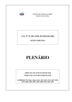
SUDS - SYSTEM CONFIGURATION (CADNETSYSTEM DESCRIPTION)
All the SUDS programs are run on CADNET systems and so it is
necessary to understand how it functions and how to
communicate with it. The following information is a brief
and simple explanation of the CADNET system and how it serves
the SUDS user.
The CADNET system on which the SUDS run on is a DEC system-10
time sharing system that contains XXXK of core (main memory)
and a monitor program that schedules and allocates processing
time and memory required for each user. Time sharing enables
multiple users to have access to a computer system at the
same time by sharing the resources of the computer between
users. In addition to main memory, the DECsystem-10 provides
secondary memory in the form of Disk Packs. These disk packs
are used for storing many types of data as well as allocating
each user a maximum amount of unique disk blocks for files
that may be created while running programs (see figure 2-1).
In order to use the CADNET sytem, all SUDS users must first
obtain a project programmer number (PPM). 'A PPN provides the
user with three important functions:
1.
2.
working area on disk where the user can store data
files created by running programs. Other portions of
the disk will be used for other PPN's to store
programs and data files.
'A
The user will identify this area by a unique PPN; a
repr~senting a project and the idividual's
number seperated by a coma (e.g. 3~2,12~)
numb~r
3.
To·protect each user from others, a unique password
is given to each user when the PPM number is
assigned.
Each time a user runs on theCADNET system, they are required
to log into the computer. This process will cause the·
computer to ask the user for a PPN, password, cost center,
and charge number. This is necessary to tell the computer
where your files are stored, and what department and project
to charge for the computer time you use.
D£C 5rSTCAII-L¢ CADlY.£T CONFfGL/,c?ATiOty
/-------
_--.--------- --_J_ -----.-.___ _
DISK,
CPU
II 0
TAPe
AllAIN
CONTROL-DRIves
DRIves MCIvIORY
LCRS @® ®0
-. ,_. __.
GC
L - - _. - -_.--.- - - -.
-~
DISK PACKS ----.....-w
(5ECC)t·JDARY A1EA10RY)
GRAPHICS
COMA'IUNICATOR
HIGH
SP££D
LINE
PRINTER
~~
DIReCTORY
MONITOR
PROGF?AA'/S
LOG ETC
.D£l_t.-T£
r:'h'(jGRAA15
VT(/).5GC
---~
GCO
L-7C
362~760
362,76'"
LTC
-
(362,120)
WRP864-DRW
~~£F6PFW WRP865-0RW
J-VITI-I DATA
f-ILLS
ETC
----.---- - --- '-'-"
.....
FIGURE
2-1
w
SUDS SYSTEM CONFIGURATION
•
14.
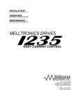
PROGRAMMABLE GRAPHICS (SUDS USER STATION)
A. Hardware
The basic SUDS system user station is a subsystem comprised
of a program that links with internal system programs to
communicate through the DECsystem-10 to display a SUDS
designer's layout on a programmable graphics processor
(PGP6A). The PGP6~ is comprised of an 11/34 minicomputer
attached to a VS6~ graphics display and an LA3~ teletype.
The SUDS designer also has the option of using a lightpen and
button box, which are attached to the PGP~~ as a means of
interacting with the graphics display tube (see figure 2-2).
Currently there are two basic configurations supported by
CADSE: a PGP configuration using DMC-ll communications and a
GT4~-like system using DLll's and an asynchronous
communications system.
In either case, a GT4~ or GT6~
graphics terminal may be used.
The host system must be DECsystem-l~ in CADNET for DMCII
configuration or any DECl~ or 2~ for the DCll communications.
B. Software
SUDS is wr i tten in MACRO-l ~ assembler language.
It is
heavily conditionalized to allow for different configurations
and operating systems (ie: TOPS-10 or TOPS-2~). The only
special systems software needed is the pcp DMC-11
communications system standard on all CADNET machines.
In both communication configurations, there is piece of
software that is resident in the suns terminal (VT~5G or
VT~5GC) that handles the keyboard and display.
This is down
line loaded from the host (-10 or -2~) or loaded from local
disk storage. The current drawing program is GeD. Also,
data bases are all stored as disk files.
----------------------------------~
I/O
DI~t}.r:JS
'rfl vf:-.
DRIVES ME:MORY CONf~~l=.-)( ® <2>@
DISK
CPU
MAIN
t - - - - - - . . - - - - I - - - - -....
r ·-- - --GC .. -
--bL
f
. - - - - - - - - - - -
I
GRAPHIC
COMA1UNICATOR
-8U.T70N BOX
'*,
rLlGHT PEN
PROGRAA1MABL£ GRAJHICS PROC£S.50R
FIGURE 2-2~
SUDS SYSTEM USERS STATION
.
......
lJl
22.
HARDWARE COMPONENTS OF CAD TOOLS
AND APPROXIMATE COST OF TOOLS
-
GEMS
POP8E, 24 f{ memory, DECta pe ,VT01-A scope,
Bendix digitizer
$3RK
CALDEC
PDP15, 9t;K MEMORY, OECTAPE, VTA4-A SCOPE,
RF15/RS~9
$47K
-
SUDS
PDPll/34, 32K memory, communication link, VRI7-LC/VTll
(SUDS onl y)
$91<
PDPll/60, 64~ memory, communication link, VS~~
(SUDS or IDEA)
$24K
Old pr ice(Must have a PDP10 or 2~2~ host)
$371<
New price-
-Terminal IDEA.
PDPll/~~,
~4T(
memory, communication link,
VS6~-AA
Old price-$24K
Host-
New price-
S37~
PDPl~, 512~ memory, communication link,
4-RP36 disks, LPl~, 2 magtapes (1~10)
DECtape
$293K
202"', 5I2K memory, commun ica tion 1 ink,
2-RM03 disks, I-mag tape (TU77)
S53K
UNIGRAPHICS
PDPI1/7~,
5I2K memory, communication lines,
4 work station graphic terminal, 2-RM~3, I-magtape,
I-plotter, unigraphic software*, 2-copiers,' spares
S3I~K
*Unigraphic licenced software price being negotiated
for substantial savings on total cost of system.
*
per graphic terminal
$221<
23.
APPLICON
P01'll/34, n4K memory, Applicon software, 1
1 large disk, 2-graphic/raster display,
2-12x12 tablets, 34x44 tablitizer terminal
rr-I~tape,
$250K
VAX BASED LAYOUT SYSTEM
Development system only - VAX/ll/78~ (STAR), 2 megbyte
memory, 2-large disks, I-magtape, I-line printer,
communication lines, VS~~ and interface
Production layout system is aimed at a low end VAX
C.1'.U. (Comet, Nebula) with a total cost in the
neighborhood of $5~K ~ $13K.
$l~~K
42.
SUDS LIBRARY
.
-
.DRW
DIPS.DIP
BOOTES
BODYOEF.
(DIPNAME)
OIPDEF.
(OIPTYPE)
I
I DRAWING" PROGRAM I
I
"
WT~ELISTI
43.
SUDS LIBRARY
The SUDS Library is comprised of two sub libraries:
.DRW and the
DIPS. DIP, which are used in tandem with each other in preparing
drawings and listings necessary in the designing of P.C. boards.
SUDS.DRW
The SUOS .DRW library consists of a collection of .DRW files which
contain well defined graphic symbols and their pin identifications.
These symbols are used by the designer to create graphic presentations
on the VS6~ display. Depending on the file selected from the library,
the designer may have access to electrical symbols, or symbols used in
designing flow charts, block diagrams, and floor plans. Figure 3-1
contains some of the electrical symbols stored in the .DRW library.
DIPS.DIP
The purpose of the DIPS. DIP 1 ibary is to provide information on the
electrical characteristics of the components represented by the .DRW
1 ibrary symbol s.
Each file within the DIPS. DIP library is automatically associated .with
a specific electrical graphic symbol, from the .DRW file, whenever that
symbol is used. This means that the output will contain not only the
.D~W symbols, but the associated DIPS. DIP files, other computer
programs (SAGE, IDEA, CALDEC, MULTIWIRE, etc.) will be able to test and
check the electrical properties of the completed design for accuracy.
When the designer is using an electrical symbol, he has the option of
referencing the associated DIPS. DIP file to add or extract additional
information. For example, assume the designer is working with a 14-pin
IC, part #19-~5575-00.
In the .DRW library, this part is represented
as four gates with the same symbol (see Figure 3-2). To distinguish
one gate from another, the designer can reference the associated
DIPS.DIP file .7400' (the number shown within the symbol) to acquire the
listing in Table one. The designer can then use the next-to-last
column of the listing (called section) to label the gates in their
appropriate order.
In this case, the gates would be numbered as shown
in Figure 3-2.
For another example, assume the designer wishes to
obtain the part number for a l~~~HMS resister he is using (shown in top
row of Figure 3-1). By referencing the DIPS.DIP RES file (the file for
all standard resistors), the designer can obtain the standard type
1 isting shown in Table 2. The designer can then reference the "P"
sublisting to obtain the 13-e0229-~0 part number.
44.
FIGURE 3-1
S_plea of Electrical Symbols . round in the SUDS
.D~
c~.t
J..
T
Library
(;NO
Ul f
1'--10h
l08V
DllU
lfNEft
DIOCE."
I
*Uef"
ZENER,"
I
*~x
J~
~
2
.2W
NUfteER
sv
.2"
51
f>' Ie> e>'
I~
74.
"""T
7'"851
~~.
~l,AY
16322
1~. 115HS
o
_
8316
12
_5
0
4
CHAR {lEN
ZKli8 RIJ"
8318
111
rtZ
"'r15
".
re'
,..,r17
ir4Rl
~:
i R,
2 AS
lAS
23
22 A8
I 9 ~.
m
ze8- CSI
I
1: g~
Z
I.
258 X 8
I- t
""ft
'f-"' II
I- 13
"1471
'f-"' 15
I- L8
"'211I""
I"
11
~
""
411
511
6M
711
1
2 - 0A
] •
tR
- 2A
5•• 3A
\7 • 'A
- SA
18
- SR
19 - 7A
15 < IS
Ifi
< 2S
l- 8
I- 7
I- 8
I- 9
I- II
I- 12
I- 13
f- I"
ft-JlEnQIC
I..
~.
!-
s.
6.
~-
Ie
11
:; I"
15
18
8.
~
45.
FIGURE 3-2
.DRW Presentation of Part 119-85575-89
PI N OROE R
. . . - _...
:
BEFORE
PIN
7400 ...- - - - - sues .ORW FILE
NO.
~74~~ ·)~-l---O'Ps.e,P FILE NO.
DESIGNATION
vB
TABLE 1
DIPS. DIP Pile Listing for .CAW Symbol '7400.
P7400
1'400
14 f'INS, VG PACKAGE TYPE
PIN •
1
2
3
4
5
6
7
B
9
10
11
12
13
14
TYPE
TIS
TIS
TO
TIS
TIS
TO
TG
TO
TIS
TIS
TO
TIS
TIS
TV
*A7400
DIP PROPERTY SUB-MODE!
**p
PART NUMBEr,
*19-05575-00
**E
DIP SUB-MODEl
*
=3
LOW
HI
-1 • {)O
-1.60
16.00
-1.60
-1.60
16.00
0.04
0.04
-0.40
0.04
0.04
-0.40
16.00
-1.60
-1.60
16.00
-1.60
-1.60
5.00V
-0.40
0.04
0.04
-0.40
0.04
0.04
22.00MA
USE
PS
SECTION RULE
1
1
1/0
2/0
3/0
1/1
2/1
3/1
2
2
3
3
4
4
3/2
2/2
1/2
3/3
2/3
1/3
46.
TABLE 2 - Excerpts from RES Listing
F'F"<ES
2 PINS
RES
F'IN t
1
2
TYPE
I
I
*ARES
II IF' F'ROPERTY SUB-HODE!
**p
VALUE
RATING
.04 OHMS
.10 OHMS
.20 OHMS
1 MEG OHMS
1 OHMS
1.lK OHMS
1.21\ OHMS
~
110 OHMS
1131< OHMS
120 OHMS
121 OHMS
12SK OHMS
1301( OHMS
1371( OHMS
140 MILLIOHMS
147 OHMS
150 OHMS
1501( OHMS
178 OHMS
180 OHMS
196 OHMS
200 OHMS
215 OHMS
220 OHMS
237 OHMS
261 OHMS
270 OHMS
2W
3W
LOW
0.00
0.00
HI
0.00
0.00
TOLERANCE
27.
1?
SW
37-
1/4W
1/4W
2.0W
1/4W
1/4W
5X
57-
.-
1/4W
1/4W
1/4W
·1/8W
1/4W
1/4W
1/4W
5W
1/4W
1/2W
1/4W
1W
2W
1/4W
1/4W
1/4W
1/4W
1/2W
1/4W
1/4W
1/4W
1W
1/4W
1/4W
1/4W
USE
lOr.
171757-
~
S7.10r.
S71717.
171'1'1717S7"1015757'17.
571157.
.10r.
5?
175757-
171?
57.
SECTION RULE
1/0
PS
2/0
PART NUMBER
*13-17515-00
*13-15240-00
*13-13358-00
*13-09595-00
*13-17522-00
*13-14350-00
*13-02645-00
*13-14491-00
*13-01320-00
~
*13-11523-00
*13-09296-00
*13-00247-00
*13-02957-00
*13-05516-00
*13-14252-00
*13-05422-00
*13-10189-00
*13-02874-00
*13-12699-00
*13-00250-00
*13-00256-00
*13-00257-00
*13-02396-00
*13-11422-00
*13-01322-00
*13-02956-00
*13-02381-00
*13-02962-00
*13-11522-00
*13-05123-00
*13-00271-00
*13-13347-00
*13-04857-00
*13-02873-00
*13-01972-00
47.
PUBLIC LIBRARIES
The user can get the body definitions from any library by using the
GETLIB command. He can also inspect the contents of any library that
has been gotten by using SL to list the names of the bodies on the
terminal or SSL to list them in a file to be printed. He can also make
a visual inspection of" the symbols contained in the libraries by
getting a set of show drawings for them from the site librarian.
The presently available libraries are these:
PTTL
HTTL
STTL
LSTTL
PARTS
NCOMP
CMOSBD
ECLSOD
CRECL
MCABD2
MOSSOD
BlOCK
FlOW
PERT
MECH
UA
SHAPES
MISC
MOSCAP
GNDCAP
Fl.ll pIa in TTL dips ( 74 04 )
All high speed TTL dips (74H~4)
All Schottky ITL dips (74S~4)
All low power Schottky TTL dips (74LS04)
Discrete components (resistors, switches, etc)
Rash mark and ground symbols
All CMOS dips (~A44)
All 1 ~ K ECL d ips (1 01 24)
All 2~8~ 1"'~f( ECL dips (CKI24)
All Venus MCA cells (C33~)
All MOS dips (36179)
Block diagram symbols
Flow chart symbols
PERT chart symbols
Mechanical parts (fan, etc)
Symbol s fo r Un i t Assembl y drawings
Forms for constructing bodies
Miscellaneous shapes
Special ~F2e capacitors
Special KLIA capacitors
To draw circuit schematics the user invariably requires more than one
library. Hence for convenience there are top level libraries that
contain 'only pointers to sets of libraries, so that getting a top level
library is equivalent- to getting all of the libraries in the set. This
is the preferred method of accessing standard libraries. Present top
level libraries and the libraries they point to are these:
TTL 1
CMOS1
PTTL STTL HTTL PARTS NCOMP CMOSBOD
CMOSBOO PARTS NCOMP
EeLl
ECLBOD PARTS NCOMP
MCA2
MOSI
MCABD2 NCOMP
MOSSOD (expansion expected)
Also, MOSCAP and GNDCAP contain pointers to PARTS and NCOMP.
48.
-SUDS
OVERVIEW
49.
SUDS OVERVIEW
(Refer to D-FD-SUOS-~-OVVl)
En9ineering - Is where the design of a p.e. board starts. The Engineer
starts by doing rough sketches of circuit schematics. When he has
completed the sketches, he submits them to SUDS for processing.
SUDS - The SUDS operator (Engineer, Technician, Drafter) will convert
~above sketches to formal drawings, using the SUDS automated drawing
program.
Once the drawings have been generated, the operator will then run the
wirelist program which will automatically generate the following
printouts used first by the designer to check out his design and
correct errors and then by CALDEC/IDEA people for reference purposes.
WL - wirelist •••• A list of net runs.
WLU - Wirelist Utilization •••• how components and pins are
utilized.
WLS - wirelist Summary •••• indicates documentation and logic
errors.
PRT
Components Part List •••• lists all the part numbers and
their descriptions that are being used on the p.e. board.
S~.
Besides automatically generating drawings and wirelist the program will
also create the multitude of files that serve as input to other CAD
processes.
Functional Verification - At this stage in the flow the Engineer has a
choice of either going the "software" or "hardware" route.
Simulation/Layout preparation (Software) - There are three programs
that an Engineer can run before going to layout.
1.
Logic Simulation - Helps the Engineer determine whether the
logic on a board or chip really works before going ahead with
layout.
2.
Placement Optimization Programs - These programs help the
designer determine the optimal position of circuit elements
from critical parameters supplied by the designer and known
characteristics of the materials, including the capacitance of
metal runs.
3.
Delay Calculation - Allows the designer to determine the
physical delays between individual signal points in a circuit
design, either a single board or a set of boards in a
backplane.
P.C. Design - The use of more up to date interactive Computer
Aided Design (CAD) System by p.e. Designers at DEC. A Computer
Aided Design (CAD) System is a combination of Hardware
(computers) and Software (programs) developed to save designers
the time and effort spent on tedious manual tasks. presently
IDEA and C~LDEC are the two C~O systems being used by the .
CAD designers.
Verification - The process by which the designer insures that
tRedrawings and P.C. board are compatible. The P. C • Designer
generates files that will automatically update SUDS drawing
files. Once the SUDS Designer has completed the update, he
generates a file that is submitted to p.e. Designer. The
Designer then uses this file to verify that the drawings and
the board are compa ti ble. Once the ver i fication ha s been
completed the board is released to production.
51.
-
SUDS
52.
SUDS
(Refer to D-Fb-suns-~-OVV2)
SUDS is comprised of three basic steps, the SUDS Input, Drawing Program
and the Wirelister.
SUDS Input - All projects start with a parts list and sketches. The
first thing to do is check to see if all the parts lists are in the
SUDS library.
If not, submit a sunSER (form for submitting new parts)
to the SUDS 1 ibrary group for implementation of new parts. Then check
sketches to make sure that all information to do the drawing is on
them.
Once the parts list and sketches have been reviewed then go on to the
Drawing Program.
Drawing Program - Is mostly for actually creating drawings, but it also
has some features that hel p in the design process: e.g. it
automatically keeps track of signal polarities and nomenclature (I/O
pins), and it has command s that allow the user to tr ace runs.
It al so
checks for polarity and dangle errors.
Closely associated with the Drawing Program is the Plot and Wirelist
Programs.
Plot Program - Creates the input file (.nPL) for various hardcopy
plotters.
Wirelist Program - Creates the input file (.WD) for the wirelist.
It recieves input generated in the Drawing
Program and automatically generates wirelist
files (WL, WLU, WLS, PRT).
WL - Wirelist
WLU - Pin Utilization
WLS - Wirelist Summary
PR~ - Component (parts) List
53.
The Wirelist Program has two main functions:
It is used to create the multitude of files that serve as input to
other c~o processes. (See Table 4)
It has many facilities to assist in catching design and
documentation errors. These errors will appear in the wirelist
files. (See Table 5)
The final stage in the SUDS process (just before release) is the
generating of a cap drawing (CAP.DRW) and prefixing all the signal
names. There are two programs that will create them automatically, the
Cap and Great Name Change programs.
car
Program - Automatically generates a cap drawing showing all the
caps that are on a P.C. board.
fi~ter
Great Name Change Program - Automatically assigns prefixes to signal
names.
>zHELF'
(~('H'if1r-IND
r
*********
*******************
MEt'tN I NG
TYPE THIS LIST
54.
TABLE 4
TOP MODE!
,!)PINHU
WI=\:I:rE' p 1:< I.,
(~~3IMPL
Des
BFIL.ES
.n L.. COM P
DL I S T
BI'1I~KAL.
BMULTI
DF:·OMUL..
E:F'F<INT
B~3El..l,.,'L
B~:)
I MPL
nr>SEL
U~::;UM
CAI...DEC
CONSUM
L!3
OfF'frE'VnCFD I F~'
I,ll:: F P P N""
OIf'MUL
DI PUtlL
DL I~ ~::; I~ F~
UI.. YL~3T
ceo
F r~ F;: ~:) U t·t
FILES
rTXCUN
! 1[{1\"'('-'
:I. CF;:r~OI\L (, '(tJUT···
"i : , I': ti L L.
;':~il·;:f.:'.l N·"·
:', CF<1...1 N
dODEl..
!'''iP(jF~ T
i"IULl IW
NETSl.lM
OUTSCH-i
F·I AF\ T
~:'ILE TO SET AUTDMATIC PIN 1:~lJl..ES FDF~ PUL.I... DC)l.~N~3
FILE, BUT ASSIGN r~EAI... PIN Nt-,MES IN PLACE DF HI.!" F'l,r: ","if:'
OUTPUT 'CS 1 CIr~CUIT SCHEMI~TIC NETWOI:;:K FILE FO!::: ~Jr~LCDr1 (BI~lCI'\;:""Ir-,IL';,'
PRINT FILE'LIST FOR BACKPANEL
WI:;: I TE' nL. elF II... F COM PA r~ IN G Tn B A C1\ P I~ NE L WI REI... I S T S
B,~CK F'I;~NEI... ~J J h:L L.l ~:) T
Wr~ITE
'~:)MP/,
WRITE' BL.. ~ tli'JD ' BI...S FILES
OUTPUT BACK PANEL 'NET' FILE TO MULTIWIRE
I
I
OUTPUT BACI\f'(iNEL.
INNEF~
l..AYEH INFO
I~S
SYSTEM
'NET' FILE TO
t1UL..TIt.JIF~E
SY~::.I:
PI~INT
Wr~IT[
wr~ I TE
BACK PI~NEI... SIGN~~L
'BSE/ I·JI...[ SELECTING EF~F~Df~ LEVEL ('BS' '[NFU)
I SMP I
F: II...F I Ncr... UD I NG ALL.. PWH P I N~3
r~ I TE' Ie S I F II" [
I~~ N D S E r... E eTC I~ T E G() F~ y ( S )
B I~ C1\ PAN E L. ~3 U j' Wi (.) I:~ Y
(] U T F:' UTe A /... DI::: ceo NN F C TIC) N LIS T
~il~I'\[ CONNEC'l'Clr~s NEEDED SLJMM(.~F~Y
OUTPUT 'C~:) I C I f<CU 1 T SCHEMAT I C NETW(JHK F I l..E For~ wr\L..COt1 (nU()h' Ct '
SET DEFAUL r DEI) I CE F()f~ I NF'UT ONL Y
~3ET DEFAUL'r D I I~[CTOF~Y F()r~ INPUT UNL. Y
SET DEF f~ULT D 11:(ECT()F~Y FDf( I NF'UT UNI... Y
OUTPUT ALL.. [I I P LOCS WITH F'()WEr~ AND Gr~(]UN[I p I N~:) TO I t1PG' F T ".. [
OUT PUT 'U M1...' F I l.. E TO 1·< E DIS T F~ I BUT E 1=< E F E r~ ENe E DES I GNAT Dr< ~;) .u "( 1.1 r r'
o IJ T PUT 1ST U I 11 ',_. L ?~ BI~ F.: :> TIM UL. US WI HE LIS T
OUTPUT 'WL' FILE AND INCLUDE WIRE DELAY FILE DATA
OUTPUT I eMIl' FILE For~ (.~DD/DELETES TO TL.E
LOG I C EHROI:< SUi1t'1~)F<Y BACK TD D
pn I NT F II,.. E l.. I ~:>T FOH CAnn
OUTPUT LIST IJF CDNNECT[)r~ PINS FOJ:( UPDATING DI~AWING~:)
SET CU H f< EN TAT W1-1 I CH "H E AV I L Y I... () I~ DE It It DC CU1\ S
ENI~BLE WIHE l.. I ~:)T I NPUT EF~I:((JI~S TO GO TO F I 1...1:::
EN()DI...E/nIDI~DI"E CHEcr\'[NG OF LAYOUT DATA
~11~KE PI~f;:TS I... T~:)T (~:)I~ME A~:) • PA/~T· )
Wr~ I TEl Wl.. I ~ .' I"J /...~) i!l AN 1) ,. WLUI F I L. F r)
nET MAF<GIN FUH r;~l!N OVEF(l..OI~D EF(f\fH~
WI:~I TE '~32M" F I L..[ r: Of< I NF'UT TO MEl<1.. I: N PI...ACErlENT SYSTEM
W/:< I TE I MIlL' FILE FOH NEWFUN FUNCT ION!:)/... MODEl... GI:::NEF<I~T ION
M(~KE Mt'ISTEr~ p()I:rrs LIST (FF((JM BAC FILES)
[) UT PUT B() AF' .u .' NET / F I L [ TOM UL T I l~ 1 r~ [ S Y~3'1" EM
OUTPUT SUMi'il·~r~ Y OF PINS I N NETS TO / L.JNS' F I l..E
w
"Jf~ITE
I Ii,'·,
ot.rrr:·Ul PIN TEHMIN(:)TION SUMM;H<Y
t·i(il\( PARTS L J ~)T (S ..4ME AS "LF'AF.:T·)
F:'PI~,F~l
MI~ 1< E ~ T 2 P / r.1::1 F~ 1 B I... I S T F J l.. E F (] f.: I NPUT T D TXT 2 F'
~J ,:~ I TEl I:) ~:) l ' !:: 11... E F CJ f~ A~3:r I S F' I~ AN CE lJ I r~ E WI:;: AP S y ~;) T [ M
F'1'~I"tNCE
i:·I-\:F.CHK-· EN(.~BI...E S I GI\}i'll .. pr~EF I x CHECK I NG
F'Sl~'iPL
Wl'<ITF '~;)MF" III...E WITH ONLY POWEr.: PINS IN IT
pcnULT OUTPUT Br],~r;:)1 TNNEr~ LI~YEF< INFO AS /NET' FILE TO r,jULTIWll:~E hY::)l[f"'j
r~[DAC
OUTPUT HEDi\C C.:(]t~NECT I ON I... I ST
r;~ E F E /:< [ .... ENABLE MUL. T I l·LL.
S T GNI~I... NfiME F~EFEI:~[NCES
;:}1~G[2
OUTPUT 'WIh'" F'ILE OF nINGI...E C,~RD Fur;: INPUT TU ~::.'!:IGE;..·.~ ~:)Ii"iUl..(lTUI?
::)I,\G,~LI...
OUTPUT 'WJI;:l FrI..1::: OF I~L..I... CAf~D~3 fUI< INPIJT lU ~3tICJF~i ~:;TI"iUI...,,(fq'··
':).r GCHI\
CHECI\ Fon I:~f"it{ fGUOUS SIGNI~L.. NAME~:i 1:'UI;: F',:')r::'l' [CIJl...f,:)F;: Cl)r11"i'~I!U
~:;.L U~)UM
:3 J M.F'LE
I
S I i'iUL.I~
',jF'FI I...E:
~;;F'F:[F I
SblMPl..
~:) ~;; P F,' [ F
~:>
.". 1~'1'r us
,'" ·f' f ~ ;::.
r.:-
MAKE SIGNAL ~UMMARY
OUTPUT I Sf'iF' F II.../:: TO DEC WI F<EL I S'1' Flo:
CltJTPUT I t~ I I,: F I t.E FOR ]. NPUT TO nt, U[:.~ ~:i I ~H.Jl..ATCH<
F~EAD ' SFT
:.3F'EC I AL. F:r L.E TEMPLATE tlND GENEF~ATE DUTr:'UT F 1 L.[
OUTPUT S I (},.)()L L. I ST FOF~ GHEi:) T S I Ci'/()/... N()/,iE CH(:)NGE
() U T P LJ TIS r<" ~:) CHEM A TIC i=< E F' I:U~ SEN T~) rILl N F CH~ M0 It U I... E T E ~3 T GE I"H:J~ I'~" TI <I '
Wf~ITE 'SM!""
. [}' A~3l\ AOOUT ~3PECJi'II...: FL,!,)TUHE!:)
OUTPUT ~:;J('1..,
.....::~jT F(H~ "Gr~E,.'iT ~:nC;i'Jttl, Ni~ME CHi:)NGE" 'I ~;;EL.ECl ur:' I j ! :
i
i
I
II
P!=\:I j-,'4"
M/.!,b:·r.:·
CUHPFN'r
flrt:.:..
II
~:;TATUS
,;:·,·tIC'C":":"l.·,
,
............................... __
~
1 ,, .. ' r\("J
\,J (.J
I
r' U 1
TEF~MLI
Wf~ I TE
Tt::ST
!,jl~:r
TLE
OUTPUT
1 I'" t:. i \ ._. U
\., t} j~ l"t I,:,l, 1 .1. l..i
TEF~M:r NAT(JI:~
r,
1".1. ....
TE CAf~ D T E ~:rn;J~ F:r L.E
55.
'CMD' FILE FOR INPUT TO TLE
'TRMWDC MAKE 'UML' FILE FClR UPDATING
NG 2 DRAWING WIRELISTS
I
r.:.
TEST PO I NT .LIST
TERMINATOI~
f~EFEF<ENCE
(rESIGNATOF~~:)
ny
I.. ·.,.::::
TF;~MWL..C
MAKE' UML' FILE F'()F~ UPDATING TEf~MINATOI~ f~EFEJ~ENCE DEBIGNATOI:;:H .rJ'r"" (.. t i !
NG DF~AWING WI"ELIST TO PC WII~ELIST
USAGE
COUNT FREE STORAGE USAGE
USED-
USE D WIRELIST
lJSEPC-
USE PC WJI:::ELIST
VGSIMP
OUTPUT BOARD TO DEC WIRELISTER
~JCtIL
DUTPUT
WLEL.. VL
~JF~ I
l.rJL I It
WLSSEL
CHANGE I D OF CUF~F~ENT WI f~EL I ST (f:;:ENAME)
WRITE 'WLS' FILE AND SELECT CATEGORY(S)
Wr~ E f:i I S
DUT F' U'I' F I /... E F (H~
TE
I
I CAl.,,'
F()f~MAT FILE FOR [lL YED AND [lLYSF~T
WLE" FILE SELECT I NG ERR{)f~ LEVEL (' WLS' I NFCl)
F~ E SIS T(] F~
rtl;~ AWIN G
lOP MODE OR DIP SUB-MODE:
tlVA I LA
LIST AVA I
CLEAR
DIIT
1...1:~BI..E
N()M[NCLATUI~ES
D~3KC()N
CLEAR CORE EXCEPT FOR RESIDENT DIP DEFS
CALL DDT
ACCEPT Try INPUT FROM DISK
HOLD [J I SK :r NPUT (CLDSES FILE)
CONTINUE DI~:)K INF'UT(/:;:EDPENS FII...E, I:;:EI~DS
DSKSKP
E CL·-
SKIP OVER LINES IN DSKIN FILE
DEFAULT PIN TYPES TO EeL IN' M<[J IF'>
H~:'LP
TYPE THIS TABLE
ftSI\IN
DSI"HLD
I
TO LAST F'O~3ITIDN)
C()MM(~ND
I WF~ C
I N F' U T W:[ r~ E FUJ LEe H E C K DE FIN I T I () N F J I... [:
I .. I S T AVA I I... (..) BI... E WI f~ E Ht.J L E S
i,J DMENC·- t;ELEt::T NOMENCLATUf<E
PAGESET LINES PER PAGE (FOR LISTINGS)
E' E n 1 II E- t"i l~ KE [J I P DEI:' ~:) F~ E S I [J EN T
SAVE
SAVE A DUMP FILE
DEFAULT PIN TYPES TO TTL IN 'M([JIP)' COMMAND
TTLWI DTH,- ~:;ET CHI~F~I~C TEI·~S PEF~ LINE (FOR LIST I NGS)
~J I F: E P 1..1··.. f:) E T / F< E ~3 E T ~J I F~ E f~ LJ L E ~)
wr~cr\~FF
OUTPUT SOME ~J:U:~E f~ULE CHECK DATA IN USEF~ F~EAnABl.E FD/;:M
~ ...
WI F~ F H
DIP bUB-MODE!
:I. DIP
INPUT 1 nIP flEFINITION FI,<OM DIP [rEF FILE
LDIF'S
LIST I~LI... DIF',},T"PEB ON TEF~MINAL
F' i~ C1\ A G.- SET / CI... E I~~ F~ I.) I;~i F( I (l n/. . E GED MET I:~ Y WI HEW F'I:') p. P,:) CI'.; (1 GET Y F' E
*
56.
TABLE 5
LEVEL 0
I/O runs that are heavily loaded
Runs with more than one I/O pin
Inactive inputs
Unused extra outputs
Runs with no unique prefix possible
LEVEL 1
Runs that are overloaded
Unused outputs
Runs with more than one pull-up
Runs wi th wire or warnings, all outputs on same DIP
Runs with wire or warnings, all outputs on different DIPs I/O runs
with wire or warnings
Runs with incorrect or missing signal prefi~es
Runs with no polarity for signal names
Runs with more than one terminator
Runs wi th questionable terminator
Runs wi th delay values not in recommended. range
Flip-flop output driving flip-flop inputs of other DIPs
LEVEL 2
Runs
Runs
Runs
Runs
Runs
wi th NO Dr i ve
with no HIGH drive
with no LOW drive
with UN or NC pins
that need termination
EeL runs with no terminator rules
EeL runs that don't match terminator rule
Runs with pull-down not needed
Runs wi th misSing pull-down
Runs wi th pull-down value not found in delay data
Runs with pull-down value f·ound but no delay data for
fan-in/fan-out
Runs with more than 2 mA of pull-down
Runs with more than four outputs
I/O runs with lower level inputs
Runs wi th no inputs or outputs
Runs wi th inputs and/or outputs connected to power
Runs with output connected to ground
Runs with power connected to ground
Runs with mixed voltages
Runs with EeL connected to TTL
LEVEL 3
Runs with signal property conflicts
Unnamed I/O runs
Runs with multiple termination rules
57.
WIRELISTER
S8.
THE WIRELISTER PROGRAM
The Wirelister produces material for Wirewrap, for CALDEC or
IDEA to generate P.C. board layouts, for the Merlin automatic
placement optimization system, and for many other procedures.
The Wirelister also has many facilities to assist the user in
both drafting and design: in the former, by such things as
checking for inconsistent signal names, and in the latter, by
keeping track of loading, power consumption, and other
physical characteristics. Drawing files of the schematics
for a circuit board or chip constitute a permanent database
that serves as the central information source for all of
these other activities.
Layout - The principle output of the wirelister is the
materials needed for input to CALDEC and InE~. The basic
item is a connection file (.CON for CALDEC and .TLE for
IDEA), which list all the wiring connections on the entire
board (sometimes with power, grounds and terminators,
sometimes without, depending upon the stage of the process).
This file should usually be on paper tape for CALDEC and on
nECTAPE for IDE~, but requirements may vary.
The other materials generated by WL are printouts used first
by the designer to check his design and correct errors, and
then by CALDEC/IDEA people for reference purposes. These
include a wirelist (.WL), a wirelist summary (.WLS), a
wirelist pin utilization (.WLU), and a component parts list
( • PRT) •
With this package, the user should of course supply a set of
circuit schematics for the board. He must also prepare a
cover sheet (CVR) listing any special directions, such as
minimum or maximum lengths for certain runs and whether
particular re·s must occupy specific positions on the board.
In addition, CALDEC requires a list (CLK) of runs of which
clock rules apply (for IDEA, this is t~ken care of by signal
properties in the .TLE file).
The process of getting a layout completed 'may involve several
transfers of material back and forth. If errors are found,
the package must be returned to the suns user for correction.
--:r any event, a prel iminary layout is returned for the user
to check that everything is where it should be, that no
problems are caused by the way things got laid out, and to
assign final component locations.
59.
SUDS itself has a number of facilities for helping with these
activities, and there are also associated programs to assist
in checking, renaming and comparing. In some cases, the user
returns to the drawing program using materials supplied by
the wirelister.
When all the problems have been solved, a final routing and
clean-up pass through C~LDEC/IDEA generates the finished P.C.
board layout.
For an ECO, the wirelister supplies a list of the changes (a
wirelister compare (.WDC) file for CALDEC, and add/delete
(.TLE) file for IDEA.
IDEA can be used for designing individual MeA chips (it is
more advanced than CALDEC and can handle many more layers).
Then with the input package limited to the external chip
connections, CALDEC or IDEA can be used for laying out a P.C.
board containing the chips.
There are three programs that the wirelister will generate
input to, which can reduce time and cost of a design. They
are the Logic Simulation, Placement Optimization, and Delay
Calculation Programs.
Logic Simulation - (see D-FD-SUl")S-~-oVV3) One of the products
of the wlreiister is a WIR. This is the input to the SAGE 2
logic simulator, which helps the user determine whether the
logic on a board or chip really works before going ahead with
layout. SAGE 2 simulates the hardware of individual gates
and logic subsystems with the ability to inspect the
interaction between individual gates in real time, to
determine whether logic actually does what it was designed to
do. An entire system can also be simulated, with inspection
at levels higher than individual gates. A similar wirelister
output (the NWS file) is used by the VOTE simulator, which
tests the effectiveness of diagnostic test patterns. programs
and microcode. In the next generation, both simulators will
use the same input.
Placement Optimization - (see D-FD-SUDS-r,,-OW l1 ) Since both
CALDEC and IDEA use placement procedures that are
particularly automated, layout can be expedited by making
prior use of the Merlin automatic placement optimization
system. These programs help the designer determine the
optimal position of circuit elements from critical parameters
supplied by the designer and known characteristics of the
materials, including even the capacitance of metal runs.
The original program, MINCUT, was specifically for placing
the 40~-gate-array chips used in the Comet project. The new
program, FINCUT, is much more general in that it is not
limited to the physical and logical characteristics of any
particular technology. Instead, for each placement run, it
gets the appropriate technological specifications from a pair
of library files: the grid file (.GRD), which specifies the
positions where packages can be placed on the physical unit,
and the log ical packages group file (. LPG), which defines the
characteristics of the components.
FINCUT exists in several versions geared to specific uses,
such as MCACUT for MCAS and ECLCUT for PC and multiwire
boards with EeL parts.
The wirelister supplies the necessary information about the
design to Merlin in the S2M file, and Merlin returns the
optimal dip and connector pin positions in the M2S file.
With this information, the designer can go back to ~AGE 2 to
get real delays and beg in a more confident layout.
Delay Calculation - (see D-FD-~UDS-0-0~'S) This software
package allows the designer to determine the physical delays
between individual signal points in a circuit design, either
a single or a set of boards in a back plane.
From the SUDS wirelist file and the CALDEC/IDEA output, DLY
creates a database that represents the physical hardware as
it would be built, and from that CAL calculates all signal
propagation times taking into account gate delays, wire
links, and even stubs. Then with DLYED, the user can
determine the delay structure of his design by inspection of
propagation times across individual elements in each signal
path.
For MeA inspection, the CAL file, which is equivalent to the
output of the CAL program, can be generated directly by the
wirelister.
The wi reI ister also generates files that input to programs
such as MULTn-lIRE, WIREWRAP, and KPL.
MULTIWIRE - (see D-FD-SUDS-~-OW6) Ut iIi zing the P.C.
program, parts of the drawing program, multiwire software
(the MDT package), outputs of the wirelister (NET and MPr,
files), and the routing rules built into the module wirewrap
program (see below) or FINCUT, the user can layout his own
multiwire boards and generate the materials for the multi wire
vendor to produce it. Sometimes these serve as prototypes
while one waits for the CALDEC/IDEA process, but where
expected volume is small, they may be used for the finished
product.
61.
Designing an etch board is much more expensive and time
consuming than multiwire, but etch boards are cheaper to
manufacture. Thus for only a few dozen units, it is probably
better to use multiwire, whereas for volume production, it
pays off to layout etch boards.
WIREWRAP - (see D-FD-SUnS-~-OVV6) Another product of the WL
program is a SMP file, which serves as input to the module
wirewrap system. These programs have built-in routing rules
and make use of three major inputs: a placement file (PLC)
that defies the coordinates of pin 1 of each dip position, a
package file (PKG) that gives the coordinates of all other
pins relative to pin 1 for each package type, and a
WL-produced assignment file (ASG) that tells what style
package occupies each position.
A similar system using the SMP files for all of the boards,
but with internal connections deleted (i.e., containing only
I/O pins) is employed for laying out the background wirewrap.
(see D-FD-SUOS-0-0VV6) The parts information on the
database (.PRT) is used as input to the KPL program.
The benefits of using this program are:
KPL -
SUDS
A.
Eliminates manual input to KPL (human errors).
8.
Minimizes document errors (part number, quantity and
reference designator) on KPL.
c.
Reduced time and cost in generating a KPL.
D.
Information sent to the KPL will be consistent.
e;2.
SUDS PROCESSES
SUDS TO IDEA
SUDS TO CALDEC
SUDS TO IDEA/CALDEC
~he
wirelister generates the materials need for input to CALDEC and
IDEA. The basic item is a connection file (CON for C~LDEC, TLE for
IDEA), which list all the wiring connections on the entire board
(sometimes with power, grounds and terminators, sometimes without,
depending on the stage of the process). This file should usually be on
paper tape for CALDEC and on dectape for IDEA, but requirements may
vary.
SUDS TO IDEA (see D-Fn-SUDS-~-PRCl) - The wirelister generates the TLE
(.CMD) file that inputs into IDEA. The p.e. designer lays out the
board and assigns pin numbers and reference designations (which may
already have been done by the Engineer).
In the layout process the
Engineer may submit design changes which will extend the completion
date of the board.
Upon completion of the board the P.C. designer will generate a UML file
that will contain all his layout changes.
He will submit this file to
SUDS.
The suns operator will process the UML file with the .DRW files
(circuit schematics). This process automatically updates the SUOS.DRW
files. Once the SUDS operator has completed the above, he will process
the .DRW files through the drawing and wirelist programs.
~he
wirelister is then used to generate a .CS file (circuit schematic
representation) that is then submitted to IDEA. The P.C. designer will
use the .CS file to varify that the suns drawings and board are
compatable.
If they are not, the above process has to be repeated.
If they are compatable, then the board is submitted to production.
SUDS TO CALDEC (see D-Fn-SUDS-~-PRC2) - Is the same process as SUDS to
IDEA except for the UML process. At that stage the P.C. desginer
generates an RLRAH tape.
The tape contains the old file (original file
submitted to designer) and new file ( file with designer's changes).
The tape is submitted to SUDS.
It is then processed using the RENAME
program which automatically updates all the .DR~N files. The drawings
and board varification process is the same as SUDS to IDEA.
64.
suns
(See
PROCESS
D-FD-SUDS-~-PRC3)
OBTAIN PPN - A PPN number can be obtained by filling out a CADNET
operations access form and submitting it to computer operations.
REVIEW PARTS LIST - Review Parts List to insure that all information on
the parts list is contained in the suns Library.
SUDS LIBRARY - Contains the defined graphics symbols and the electrical
characteristics of components.
RUN GCO/GTD - Puts you into the SUDS drawing program.
CREATE .T)RW FILE - The .D~W file represents a drawing (circuit
schematic, flow and block diagrams, floor plans, etc) which is
generated by calling bodies from the suns Library.
DANGLE POINTS - (.XDA) Checks for two types of dangle points.
a) 'A stand alone po int, which has no log ieal function - it just
clutters up the .DRW file.
b)
A line that has a missing signal name will have a dangle
point error message.
POLARITY CHECK (XPOLCK)- Checks for polarity errors.
checks the .DRW file for polarity errors such as:
This command
a)
A high signal connected to a low signal
b)
A signal name that has the high indicated in the name but
connected to a low input/output of a body or in reverse.
PLOT XEP (.DPL)- Is the process by which the SUDS designer
generates a .DPL file, which is used as the input into the "PH
(plot) program.
WIRING DIl\GRAM XEL (.WD) - Is the process by which the suns
designer generates a .WD fiel, which is used as an input into the
wirelister program.
65.
WIRELISTER (WL)- ~ set of SUDS wirelist files (WD) is the source of
information for the wirelister program (WL), which from it generates
all sorts of option files for other programs.
XMARALL - Is the wirelister command that will automatically
generate the following files and listings:
Wi rel i st
( .WL)
Wirelist Summary
(.WLS)
Wirelist Utilization
Parts List
OPTION FILES progr ams.
(.WLU)
(.PRT)
suns
output files that are used for input to other
XTLE - Generates a .CMD file for input to IDEA
XCALDEC - Generates a .CON file for input to CALDEC
XCS - Generates a .CS file for input to IDEA and CALOEC to do
a wirelist compare (WLCOMP) to insure that the drawings and
PC board are compatible.
SAGE 2 - Generates a .WIR file for input to the
simulator.
S~GE
2 logic
RENA~E PROGRAM - The rename program receives an RL8AH tape from CALDEC,
which contains an old and new file. These two files are processed
using the rename program to generate an .UML file, which is used as an
input to the GCO/GTC program to automatically update the .ORW file.
PLOT PROGRAM (RU P.) - Running the plot program "PH on a set of SUDS
plot files (.DPL) results in a .PLO file, which serves as an input to
most of the different hardcopy units (Versatic, Varian, and CAL-COMP)
to produce a plot of the finish drawing.
GREAT ~A~E CHANGE - Is used to put prefixes on all signal names.
generates a change file (.CHG) that is used to input to GCD/GTC
programs.
It
CAP PROGRAM - Is a program that automatically generates a cap drawing
(CAP. DRW)· showing all fil ter caps that are on the board.
Conclusion
The days of the Engineer designing with rough sketches of circuit
schematics, changing them frequently and scribbling directions to the
drafter allover them are numbered.
An automated design system eliminates much of the:
-Effort required to produce a finished drawing.
-Sources of error in communication between Engineer,
and drafter/technician.
p.e. designer
-Drafter's/Technician's erasing or sticking an added circuit
element way off at the edge, disconnected from its associated
logic. Instead he just changes the file and plots anew.
-Inconsistencies in drawings (symbols, lettering, and line
thickness) •
the user the most significant factor is that the products of the
system are data files that can be handled by a computer; every hardcopy
of a drawing is simply a copy - there is no original paper. This means
much shorter turnaround time both for development changes and later
ECO's. It means much greater accuracy, specially for repetitive
operations and common elements used in a number of situations.
~o
The advantages of
suns
over manual drafting are:
-Much less drafting is required to translate a sketch into an
initial drawing. Manually it would take ten to twelve hours to
do a drawing vs six to eight hours if done on SUDS.
-It automatically keeps track of signal polarities and
nomenclature (I/O pins). ~anually it would be very time
consuming and costly to do the above.
-It allows the user to automatically trace runs. The
drafter/technician would have to physically trace runs.
-Has many facilities to assist in catching design and
documentation errors.
-Has many facilities to assist in catching design and
documentation errors.
F.7.
-~anually
it would involve the Engineer and drafter/technician
to manually check drawings and design to catch the above errors,
where as SUDS will do it automatically. That leaves the Engineer
and drafter/technician time to do more productive work. The
major advantage of an automated system is not so much a saving in
total drafting as an ability to do a great deal more useful work
in the time available: just having more information on the
circuit schematics makes them more valuable to Field Service,
Manufacturing, and other users. In many cases using SUDS allows
activities that would otherwise be impossible. Suppose for
example that as a production deadline approaches, it is decided
the signal prefix used on a group of a dozen drawings is
misleading in light of the way the design has evolved. A manual
drafting department would simply inform Engineering that nothing
could be done about it. But an automated department would have
just suns search through the files for all instances of the
prefix and change them. Some Engineers have become adept enough
at using the system so that they even make minor revisions (such
as IC substitutions) at an office terminal with no graphic
display at all.
I hope the suns OVerview has enlightened you to what SUDS is and what
it can do for the Engineering and Rngineering Services Community, in
reducing design time and cost.
Please feel free to call me, Norm Rheault, Ext. 223-R 7 89,
more information.
ML4-2/E9~
for
WHAT IS THE SUGGESTED MODULE DESIGN PROCESS USING SUDS?
A. THE BEST TIME TO CAPTURE THE LOGIC INFORMATION (SCHEMATIC)
IS DURING IT'S CREATION. AT THIS TIME} SUDS CAN BE
OP ERATED BY THE ENG I:NEER OR TECHN I CI AN.
B.
WHEN SCHEMATICS HAVE BEEN DEVELOPED TO THE BREADBOARD STAGE}
A WIREWRAP BOARD CAN BE PRODUCED IN A MATTER OF DAYS OR A
"QUICK AND DIRTY" P.C. LAYOUT IN WEEKS ••• BOTH USING THE
DATA BASE.
C.
DURING DEBUG J GROUPS OF CHANGES ARE ENTERED TO THE ON-LINE
SUDS DATA BASE TO ASSURE THE DATA BASE ALWAYS MATCHES THE
BREADBOARD.
D.
THE FINAL DATA BASE FROM
DIRECTLY TO P.C. LAYOUT
OF THE DATA BASE CAN BE
WIRELIST OF THE CHANGES
E.
THE MIF CAN BE COMPARED TO THE WIRELIST FROM THE ENGINEER'S
PRINT SET ASSURING A MATCH.
THE DEBUGGED SCHEMATICS IS SENT
WITH NO HAND CODING. Two VERSIONS
COMPARED AUTOMATICALLY AND A
REPORTED.