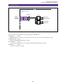
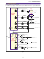
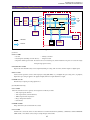
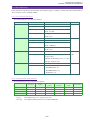
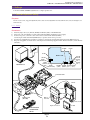
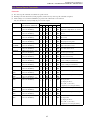
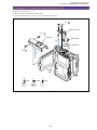
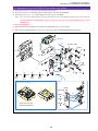
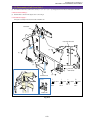
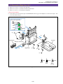
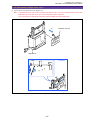
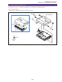
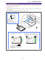
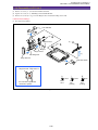
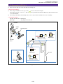
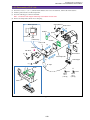
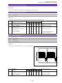
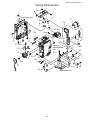
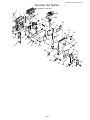
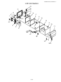
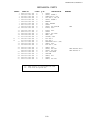
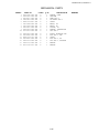
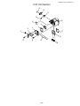
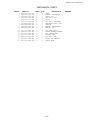
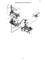
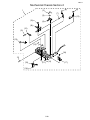
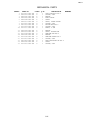
1
Video Product
ELURA20 MC A
ELURA10 A
No. D17-6512
D17-6522
Digital Video Camera
NTSC
Canon Inc.
Digital Imaging Products Service Dept.
c CANON INC. 2001
First Edition : Sep. 2001
First Print : Sep. 2001
CHAPTER 1. GENERAL DESCRIPTION
CONTENTS
1. Product Overview ---------------------------------------------------------------------------------------------------------------------------- 1-1
2. Product Features ------------------------------------------------------------------------------------------------------------------------------ 1-1
2-1 Comparative List for Functions and Performance -------------------------------------------------------------------------------- 1-3
3. Performance / Functions ---------------------------------------------------------------------------------------------------------------------- 1-6
4. System Charts --------------------------------------------------------------------------------------------------------------------------------- 1-13
5. Viewfinder/ LCD Display Internal Display List ----------------------------------------------------------------------------------------- 1-14
5-1 Camera Mode ------------------------------------------------------------------------------------------------------------------------- 1-14
5-2 VCR Mode ---------------------------------------------------------------------------------------------------------------------------- 1-18
5-3 Card Recording Mode (MC Model Only) ---------------------------------------------------------------------------------------- 1-22
5-4 Card Play Mode (MC Model only) ------------------------------------------------------------------------------------------------ 1-26
5-5 Menu Displays ------------------------------------------------------------------------------------------------------------------------ 1-28
5-6 Card Mix Screen Displays ---------------------------------------------------------------------------------------------------------- 1-35
5-7 Warning Display ---------------------------------------------------------------------------------------------------------------------- 1-40
6. Data Backup ---------------------------------------------------------------------------------------------------------------------------------- 1-42
6-1 Main Power Supply Backup -------------------------------------------------------------------------------------------------------- 1-42
6-2 Backup by the Main Power Supply or Backup Power Supply (Button Type Lithium Primary Battery) ---------------- 1-42
6-3 Backup Conditions Using Switch Operation ------------------------------------------------------------------------------------- 1-43
6-3-1 Turning OFF the Power Supply ----------------------------------------------------------------------------------------- 1-43
6-3-2 Other Power Switch Positions ------------------------------------------------------------------------------------------- 1-44
6-3-3 Switching the Camera Mode/Switching the Program AE Mode --------------------------------------------------- 1-45
7. Others ----------------------------------------------------------------------------------------------------------------------------------------- 1-46
7-1 Green Mode --------------------------------------------------------------------------------------------------------------------------- 1-46
7-2 On-Screen ----------------------------------------------------------------------------------------------------------------------------- 1-46
7-3 Headphone (with Docking Unit DU-300 Connected), Speaker --------------------------------------------------------------- 1-46
7-4 Battery Level display, Warning Displays and (Low-Power) Power Shutoff ------------------------------------------------- 1-47
7-5 System Data Display ----------------------------------------------------------------------------------------------------------------- 1-47
7-6 Data Code display -------------------------------------------------------------------------------------------------------------------- 1-47
7-7 MP Tape Capability ------------------------------------------------------------------------------------------------------------------ 1-47
7-8 Warning Buzzer ---------------------------------------------------------------------------------------------------------------------- 1-47
7-9 Using Analog Line, DV Recording ------------------------------------------------------------------------------------------------ 1-48
7-10 VIdeo ID1 Detection/Output Capability ----------------------------------------------------------------------------------------- 1-48
7-11 Closed Caption Detection/Output ------------------------------------------------------------------------------------------------ 1-49
7-12 Audio Dubbing --------------------------------------------------------------------------------------------------------------------- 1-49
7-12-1 Tape Usable for Audio Dubbing --------------------------------------------------------------------------------------- 1-49
7-12-2 Selecting an Audio Dubbing Signal Input Source ------------------------------------------------------------------ 1-49
7-12-3 Audio Dubbing Operation ---------------------------------------------------------------------------------------------- 1-49
7-13 AV Insert ---------------------------------------------------------------------------------------------------------------------------- 1-50
7-13-1 Tape Usable for AV Insert ---------------------------------------------------------------------------------------------- 1-50
7-13-2 AV Insert Operation ----------------------------------------------------------------------------------------------------- 1-50
7-14 Multi-Dial ---------------------------------------------------------------------------------------------------------------------------- 1-50
7-15 LCD Panel/CVF (Color ViewFinder) -------------------------------------------------------------------------------------------- 1-51
7-15-1 Camera Mode/Camera Recording Mode ----------------------------------------------------------------------------- 1-51
7-15-2 VCR Mode/Card Play Mode ------------------------------------------------------------------------------------------- 1-51
7-16 Memory Card System -------------------------------------------------------------------------------------------------------------- 1-51
7-16-1 Card Recording (Card Recording of Still Images) ------------------------------------------------------------------ 1-51
7-16-2 Copying [
]/[
] ---------------------------------------------------------------------------------- 1-52
7-16-3 Card Mix ------------------------------------------------------------------------------------------------------------------ 1-53
7-16-4 Card Playback ------------------------------------------------------------------------------------------------------------ 1-53
7-16-5 Image Protecting Setting ----------------------------------------------------------------------------------------------- 1-54
7-16-6 Print Mark Setting ------------------------------------------------------------------------------------------------------- 1-54
7-16-7 Image Erase --------------------------------------------------------------------------------------------------------------- 1-54
7-16-8 Format --------------------------------------------------------------------------------------------------------------------- 1-55
7-16-9 Card Review -------------------------------------------------------------------------------------------------------------- 1-55
7-16-10 Image Setting ----------------------------------------------------------------------------------------------------------- 1-55
7-16-11 Forward Skip for Card Playback ------------------------------------------------------------------------------------ 1-56
ELURA20 MC A, ELURA10 A
CHAPTER 1. GENERAL DESCRIPTION OF PRODUCT
1. Product Overview
Strategic product with a 3x recording mode, memory card functions and analog line input (iPAL) that are newly developed in the
camcorder industries. Also, it succeeds the super compact size of the ELURA2 MC A with more sophisticated exterior design and
enhances the picture quality.
2. Product Features
• Compact vertical (magnesium alloy) body
• 1/4-inch progressive scan 680,000-pixel CCD RGB primary color filters
• 2.5-inch 200,000-Pixel LCD monitor
• Digital input/output (DV jack), analog input/output AV insert function
• Card still image recording, multi-media card, SD memory card capability (MC model only)
• Card mix function (MC model only)
• SDL mode (max. recording time 240 min. : ELP mode using 80 min. tape)
• Multi-screen
• 3-element microphone
• Adequate accessories (New : 1 types of optical accessories, compact power supply)
• User-friendly card functions (Card preview, card playback jump functions)
1-1
ELURA20 MC A, ELURA10 A
CHAPTER 1. GENERAL DESCRIPTION OF PRODUCT
External Appearance
Fig. 1-1
1-2
ELURA20 MC A, ELURA10 A
CHAPTER 1. GENERAL DESCRIPTION OF PRODUCT
2-1 Comparative List for Functions and Performance
Item
ELURA2 MC A, ELURA2 A
ELURA20 MC A, ELURA10 A (this device)
Camera
Imaging(video) Image size
1/4-inch CCD
←
element
Number of pixels
Total number of pixels : 680,000
←
Effective number of pixels : 360,000
←
System
Progressive scan
←
Filter
RGB primary color filters
←
Optical zoom ratio
10 ×
←
Digital zoom ratio
40 × (10 × 4)
←
Focal length
3.5-35mm
←
(Converted to 35mm film)
44.7-447mm
←
F number
F1.6-2.6
←
Zoom speed
Variable
←
Filter diameter
27mm
←
Minimum brightness
7.5 (3.5) lux (low-light mode NTSC: 1/30 sec)
←
Hand jitter compensation
Electronic type
←
(Full auto)
←
Lens
Recording function
Program AE
(Auto/Sports/Portrait/Spotlight/
Surf(sand)& snow/Low-light)
Light metering Lower center weighted
Full auto mode, Auto mode, Sports mode,
system
Portrait mode, Low light mode
averaged metering
Evaluation metering
←
←
128 sectors
(spotlight mode, surf (sand) & snow mode)
Exposure
AE lock
●
←
adjustment
Exposure compensation
● (after AE lock)
←
AE shift
×
←
Gain setting/Higher sensitivity ×
←
Backlight compensation
×
←
6 steps
←
Shutter speed High-speed shutter
(1/60, 1/100, 1/250,1/500, 1/1000, 1/2000)
Slow shutter
1 step (1/30 (Low-light, AE mode))
←
Auto iris
←
Image quality
Color gain adjustment
×
←
adjustment
Color phase adjustment
Aperture
×
←
×
←
Setup adjustment
×
←
Auto
●
←
(Custom preset) Sharpness adjustment
WB
Focus
16:9
Set
● (1 pc.)
←
Preset
Outdoors/indoors
←
System
TTL, 128 sectors
←
Mode
AF/MF
←
Manual focus
Multi-dial operation
←
Recording system
Vertical extension system
←
Area marker display
×
←
Recording
D. effect
Art, black & white, sepia, mosaic
←
effects
D. fade
White(black)auto, wipe(right & left), scroll, mosaic White(black)auto, wipe(right & left), scroll, mosaic
Multi-screen
4/9/16 screen (MC model only)
← (MC model only)
×
←
Zebra pattern
1-3
ELURA20 MC A, ELURA10 A
CHAPTER 1. GENERAL DESCRIPTION OF PRODUCT
Item
ELURA2 MC A, ELURA2 A
ELURA20 MC A, ELURA10 A (this device)
Recording function
Color bar
×
←
Movie
Framed movie
Progressive scan
←
recording
Self-timer
10 sec/remote control : 2 sec
←
Interval timer
×
←
Clear scan
×
←
Recording system
Frame recording (MC model only)
← (MC model only)
Still image
recording
(tape)
(Field recording for card mix)
Recording time
6.5 sec.
6.5 sec. (ESP/ELP:approx. 8 sec.)
Frame processing
Progressive scan
←
Still image
Recording system
Frame recording (MC model only)
← (MC model only)
recording
Recorded image size/file system 640 (H) × 480 (V) / JPEG (MC model only)
(Card)
Memory card
← (MC model only)
Multi-media card
Multi-media card, SD memory card
REC search
●
←
REC review
●
←
Card review
×
★ (MC model only)
Standby SW
×
←
Power save(after 5-min. recording pause) Power shutoff
←
Displayed character recording
×
←
Audio
16 bits 2 ch (48KHz)
←
12 bits 4 ch (32KHz)(No sync 4-ch recording)
● ON/OFF switch (for built-in microphone only) ←
Wind cut
EVF
Monitor LCD
Size
0.44-inch (color TFT)
←
Number of pixels
113,000 pixels
←
Brightness adjustment
×
←
Color adjustment
×
←
Portable
×
←
Size
2.5-inch
←
Number of pixels
200,000 pixels
←
Brightness adjustment
×
←
Portable
● Mirror photography capability
←
VCR
Playback
Frame forward play
Forward/reverse
←
system
Slow play
Forward/reverse
←
2× speed play
Forward/reverse
←
1× speed play
Forward/reverse
←
Queue/review
9.5 × speed play
←
Photo search
●
←
Search
Date search
●
←
Index search
×
←
D. effect
Art, black & white, sepia, mosaic
←
D. fade
White(black)auto, wipe(right & left), scroll, mosaic ←
Multi-screen
4/9/16 screen (MC model only)
← (MC model only)
Date display/camera data
←
Slide show
● (MC model only)
← (MC model only)
Card playback jump
×
★ (MC model only)
Audio dubbing
●
←
●
←
Play effect
Data code display
AV insert
Digital
Analog
Zero set memory
●
←
●
←
1-4
ELURA20 MC A, ELURA10 A
CHAPTER 1. GENERAL DESCRIPTION OF PRODUCT
Item
ELURA2 MC A, ELURA2 A
ELURA20 MC A, ELURA10 A (this device)
VCR
Edit function
Simple edit
×
←
Effects
×
←
Microphone input
● (DC 5V jack, DU-300 capability)
←
Headphone output
● (DU-300 capability)
←
DV jack
● (input/output)
←
S jack
● (input/output, DU-300 capability)
← (input/output, DU-300 capability)
Systems
I/F(jack)
input/output RCA pin (also used for VA)
← (also used for VA)
LANG jack (DU-300 capability)
←
World clock
●
←
Character title
×
←
Speaker
●
←
Warning buzzer
●
←
Tally lamp
●
AV jack
Edit capability
←
1,
Remote control
2 capability
←
Accessory shoe
×
←
Video ID
● (ID1)
←
Recording
LP
●
←
mode
SDL ( E SP, E LP)
×
★
Custom key
×
←
Index screen key
×
★ (MC model only)
Mix/slide show key
×
★ (MC model only)
DV control
×
←
Main unit charging
×
←
Backup power supply
Button type lithium battery (CR-1616 type)
←
Battery pack power supply
Lithium battery, 400 series
←
Changed from D52A/B models (★ : New functions)
1-5
ELURA20 MC A, ELURA10 A
CHAPTER 1. GENERAL DESCRIPTION OF PRODUCT
3. Performance / Functions
ELURA20 MC A, ELURA10 A
Video camcorder
1 Type
2 Recording system
2-1 Video signal recording system
Sampling frequency
Number of quantified bits
2-2 Audio signal recording system
2-3 Tracking
2-4 Tape speed
2-5 Head drum
Drum diameter
Speed
Number of heads
3 Record/play times
Continuous recording time BP-406
BP-412
BP-422
4 Usable video cassettes
4-1 Tape type
4-2 Tape width
4-3 Tape thickness
5 Camera
5-1 Video element
5-1-1Number of pixels
5-1-2 Filters
5-1-3 Color separation system
5-1-4 Signal configuration
5-1-5 Scan system
5-2 Optical lens
5-2-1 Nominal focal length
Zoom ratio
(Converted to 35mm film)
5-2-2 Nominal aperture ratio
5-2-3 Lens configuration
5-2-4 Focusing
5-2-5 Minimum focusing distance
5-2-6 Power zoom
5-2-7
5-2-8
5-2-9
5-2-10
5-2-11
5-2-12
5-2-13
Rotary 3-head helical scan azimuth recording.
Personal digital DVC (SD/SDL standard).
Conforms to the NTSC system (525 lines x 60 fields).
Digital component recording.
SD
SDL
Y = 13.5MHz
Y = 10.125MHz
R-Y, B-Y = 3.375MHz
R-Y, B-Y = 3.375MHz
8bits
8bits
PCM digital recording.
PCM digital recording.
16-bit, 48KHz 2 channels
-------12-bit, 32KHz 2 channels
32KHz 2ch
(stereo 1, 2)
(stereo1)
2-frequency pilot type
2-frequency pilot type
Approx. 18.81mm/sec. (SP mode)
Approx. 9.41mm/sec. (ESP mode)
Approx. 12.56mm/sec. (LP mode)
Approx. 6.28mm/sec. (ELP mode)
21.7mm
9000/1.001 rpm
3 video heads
Max. 80 min. (SP mode)
Max. 160 min. (ESP mode)
Max. 120 min. (LP mode)
Max. 240 min. (ELP mode)
Approx. 55 min. (CVF), Approx 45 min. (LCD)
Approx. 100 min. (CVF), Approx 80 min. (LCD)
Approx. 200 min. (CVF), Approx 165 min. (LCD)
Mini-DVC specifications.
Evaporated metal tape.
6.35mm evaporated metal tape.
7µm
1/4 (1/4-inch) type progressive scan CCD.
Total number of pixels: approx. 680,000
Effective number of pixels: approx. 360,000
RGB primary color filters.
Differential read-out type.
NTSC standard color video signal
525 lines x 60 fields / 30 frames
3.5mm - 35mm
Optical lens: 10× Electronic zoom: 40× (10× 4 = 40)
44.7mm - 447mm 1788mm (equivalent)
1 : 1.6 (F2.6 at Tele photo-end)
10 elements, 7 groups, 2 aspherical lens elements (3 surfaces) used.
Inner focus type. Manual focusing is also possible (by rotating the Multi dial).
10mm (autofocus at Wide). 1m (from the front of the lens) throughout the entire zoom range.
Multi-step, variable speed power zoom. Slide lever type. The zoom speed is varied by the
amount of slide lever movement.
Optical zoom: approx. 2.0 sec. - approx. 21 sec.
Digital zoom: approx. 3.5 sec. - approx. 24 sec.
No manual zoom (no zoom ring).
Focal length indication
None. There is a simple zoom display in the viewfinder.
Macro mechanism
Wide angle end macro.
Minimum macro focusing distance 10mm (from front of lens).
Filter diameter
27mm, P0.5mm
Accessory lenses, filter
FS-27U can be used.
Lens hood
None.
Lens cap
Covering type.
1-6
ELURA20 MC A, ELURA10 A
CHAPTER 1. GENERAL DESCRIPTION OF PRODUCT
5-3 Hand jitter compensation
5-3-1 Type
5-3-2 Hand jitter detection
5-4 Recording modes
5-4-1 Movie mode
5-4-2 Photo mode
5-4-3 Card recording
Yes
Electronic type hand jitter compensaion
Angular velocity detecting method.
Movie mode, photo mode (tape and card recording (card for ELURA 20 MC A only)).
Normal recording and progressive scan recording.
Approx. 6.5 sec. (approx, 8 sec. int the ESP mode and ELP mode) still image recording (field
recording for card mix in frame record and movie mode)
Lock display ( ) in the viewfinder after partially pressing the button. This display lights green
when the AF lock is applied.
CCD Prograssive still images can be recorded an still images on MMC (Multi-Media cards) or
SD (Secure Digital) memory card by pressing the Photo button int the card recording mode. A
shutter tone (pseundo) will sound at his sound at this time.
Recording system JPEG.
JPEG system compressin ratio (fine/standard) available.
Conforms to DCF (Design rule for Camera File system).
Recording system
JPEG system compensation ratio (irreversible) (fine/standard) available
Conforms to DCF (Design rule for Camera File system).
Number of recordable images (for SDC-8M)
Fine
Approx. 50
Standard
Approx. 80
The SDC-8M card supplied contains pre-recorded title images, so the above values will be
smaller when this is used. The values are merely guidelines and can vary widely depending on
the focal length used, the subject, the conditions, etc.
5-5 Exposure control
5-5-1 AE function
Program AE
5-5-2 Light metering system
Full auto mode, auto mode, sports mode, portrait mode, spotlight mode,
surf (sand) & snow mode, low light mode.
Below-center weighted averaging metering :
Full auto Mode, Auto Mode, Sports Mode, Portrait Mode, Low Light Mode.
Full frame averaged metering + 128-sector evaluation metering :
Spotlight Mode, Surf (Sand) & Snow Mode.
128 sectors (16 vertical x 8 horizontal)
Frame division
5-5-3 Exposure compensation function
AE lock
AE lock by AE shift button operation AE lock uses the Multi-dial for Exposure compensation
(except in Full Auto mode).
Exposure Compensation volume
+/−11 steps (+/−2.75EV), 0.25 aperture stop per step. Bar indicator (
) in the
viewfinder.
5-5-4 Electronic shutter
High-speed shutter
Low-speed shutter
5-6 Autofocus (AF)
5-6-1 System
5-6-2 AF measurement area
5-6-3 Metering frame display
5-6-4 AF operational range
5-6-5 AF operational brightness range
5-6-6 AF mode selection
Manual focus
5-7 Viewfinder
5-7-1
5-7-2
5-7-3
5-7-4
Rotation
Eyepiece removal
Diopter adjustment range
Lens configuration
Auto mode : 1/60 sec., 1/100 sec., 1/250 sec., 1/500 sec., 1/1000 sec., 1/2000 sec.
Hand jitter compensation ON
During flicker detection : 1/100 sec.
During flicker detection : 1/120 sec.
Hand jitter compensation OFF
During flicker detection : 1/100 sec.
1/30 sec. (low light mode, fixed speed)
TTL, video signal detection auto focus type AF.
Center of screen
None.
10mm - infinity (Wide); 1m - infinity (from front of lens) throughout the entire zoom range.
50 lux - 100,000 lux
Continuous AF/manual focusing. AF can be turned on and off by pressing the focus button in all
modes except full auto. (Pressing focus button)
is displayed in the viewfinder during manual focus (AF off).
0.44-inch type, color liquid crystal display (approx. 113,000 pixels), telescoping type (pull out).
Off except when the LCD monitor is stored (body side panel face) and during mirror mode.
No.
Yes.
+1.5 to –5.5 diopters (eyepiece).
2 groups, 2 elements.
1-7
ELURA20 MC A, ELURA10 A
CHAPTER 1. GENERAL DESCRIPTION OF PRODUCT
2.5-inch type, color liquid crystals, display approx. 200,000 pixels (228 (V) × 880 (H)). TFT
active matrix drive.
RGB delta array. On except when the LCD monitor is stored (body side panel face).
Yes. High angle, low angle, monitoring during mirror mode.
Operation mode display, simple zoom position display, battery level display, remaining tape
display, time code, various warning. Color display. No display during mirror mode.
5-8 LCD panel
Angle adjustment
Data display
Relationships to the viewfinder (CVF)
Camera mode/card recording
LCD panel position
LCD panel
*1
VCR mode/card playback
CVF
LCD panel
CVF
Panel closed (panel side of body)
OFF
ON
OFF
ON
Panel closed (panel side outside)
ON
OFF
ON
OFF
ON
OFF
ON
OFF
ON
ON
ON
Panel opened
Mirror (photography) mode
*3
ON
*2
*1
*1: ELURA20 MC A only
*2: Appears in Mirror mode with menu operation.
*3: Panel displays restricted to the following for Mirror mode. (Normal viewfinder and onscreen displays)
The following marks are indicated in the upper left of screen .
• Camera mode
: “●” recording , “
” recording pause,“ ”ejection
• Card recording mode : “
” without card , “
<<<<”with card, accessing
(Mirror mode is reset in recording search and warning.)
TTL, 128-sector, new white extraction type FAWB.
5-9 White balance adjustment
With set/preset (outdoors: 5,600K; indoors: 3,200K) (selection from camera menu).
2,800K - 8,000K.
Adjustment range
5-10 Digital feature function
Fader, effects, multi-screen, card mix (MC model only) modes are provided.
Fader
: Coupled to the start/stop button (VCR mode button), one-time execution is possible
when the fader mode is displayed (the mode display disappears when the fader ends).
Effects
: Continuous effects are possible until turned off.
Multi-screen : Images are captured and displayed on several screens at fixed intervals or as
indicated manually. Displays continue until turned off.
Card mix
: The sample images supplied and images recorded on cards can be mixed and
displayed with images captured with the camera.
Audio-synchronized fader.
Auto fade (JAPAN models: White Fade; Overseas Models: Black Fade),
Wipe (Left/Right), Scroll, Mosaic Fade.
Approx. 4 sec.
Art, Monochrome, Sepia, Mosaic.
Operated by pressing the Effects button to toggle this function ON and OFF.
5-10-1 Fader
Fade time
5-10-2 Effects
5-10-3 Multi-screen
Number of screens
4 (2 × 2, 9 (3 × 3), 16 (4 × 4)
Operation mode
Manual, fast (every 4 fields), normal (every 6 fields), slow (every 8 fields).
5-10-4 Card mix (MC model only)
Mix type
Card chroma key, Card luminance key, Camera chroma key
Mix level adjustment
32 steps.
5-10-5 Relationship between digital features and operation mode
When execution is possible in the various modes (Card record mode, card play mode. Card mix only with the MC model.)
Fader
Effects
Multi-screen
Card mix
Card record
mode
×
○
○
×
Camera mode
Still Image
Movie
×
○
○
○
○
○
*1
○
○
VCR mode
○
○
○
×
Card playback
mode
×
×
×
×
*1: Not possible in the movie mode or low light mode (interlace).
1-8
ELURA20 MC A, ELURA10 A
CHAPTER 1. GENERAL DESCRIPTION OF PRODUCT
5-11 Built-in microphone
5-11-1 Wind cut function
5-12 Additional functions
5-12-1 Time code
5-12-2 Data code
Date/time
Camera data
5-12-3 Assessory shoe
5-12-4 Image search function
5-12-5 Rec review function
Stereo microphone (electret condenser microphone used).
Stereo using on-directional microphone × 3 + electrical circuit (3-element microphone).
With on/off switch (menu selection for built-in microphone only).
Recording time (0:00:00 - 7:59:59) is displayed and recorded in the sub code area.
There is no recording time display, but the recording date/time and camera data are recorded
and can be displayed during play.
Coupling range: January 1, 2001 to December 31, 2030 (initial setting: January 1, 2001).
World time capability. Automatic setting to the date/time of travel destinations by selecting the
destination city. Daylight saving time capability. Three display modes are available for play:
date, date and time, and time (January 1, 1990 to December 31, 2089).
Values such as shutter speed and aperture value are recorded (no display during recording) and
can be displayed during play.
None.
Tape can be played (forward/reverse) during camera recording pause by operating the Rec Search button.
Started by operating the Rec Check button (
) during camera recording pause.
5-12-6 Card review function
Yes (MC model only) The last image recorded on the memory card is read out by operating the
REC Check button ( ) on the card recording mode. The image read out can be protected or deleted.
5-12-7 Zero set memory
Yes. Tape can be forwarded or rewound continuously until the zero set memory key of the WLD75/WL-D76 is operated (The counter value is set to 0:00:00.) (Zero set is possible only during
recording, not during play.)
5-12-8 Remote control ON/OFF
5-12-9 Selftimer
5-12-10 Headphone volume adjustment
6 Recorder unit
6-1 Recording functions
6-1-1 Recording format
6-1-2 Tape speed
SD specifications
SDL specifikations
6-1-3 DV input recording
6-1-4 Analog input recording
6-1-5 Terminal priority during recording
6-2 Insert recording
6-2-1 Insertable tape
6-3 Dubbing
6-3-1 Tapes usable
6-3-2 Dubbing signal input
6-3-3 Dubbing selection
6-4 Play functions
6-4-1 Standard play
a. Video
b. Audio
16-bit
12-bit
6-4-2 Special play
a. Freeze frame play
b. Fast forward play
c. Rewind play
d. Frame forward play
e. Slow play
f. 1× speed play
g. 2× speed play
h. Edit search
Yes. Available in both the camera recording and the VCR modes (menu selection).
10 sec. (Approximately 2 sec. when the wireless controller WL-D75/WL-D76 is used.)
Adjustment is possible using the multi-dial.
Camera recording, DV input recording, analog input recording.
Personal DVC (SD specifications).
Approx. 18.81mm/sec. (SP mode), approx. 12.56mm/sec. (LP mode)
Approx. 9.41mm/sec. (ESP mode), approx 6.28mm/sec. (ELP mode)
Conforms to IEEE 1394.
Records video and audio signals from a digital video camera connected with the DV cable.
The S-video jack and AV mini-jack are used to recordanalog video and audio signals.
DV jack > S-video jack > AV mini-jack
Yes.
Only tapes with SP recording can be inserted.
Yes (SD specification tape only)
Only tapes with 12-bit SP recording other than for audio dubbing 4-channel simultaneous recordings can be used for dubbing.
Line (AV mini-jack) or microphone (external/internal) audio signals.
Operate the dubbing button of the remote control in play pause status.
Standard play and special play
Video recorded in the SP, LP, E SP or E LP mode
Sampling frequency 48KHz, 44.1KHz, 32KHz. (except for SDL specifications)
Sampling frequency 32KHz.
Play using stereo 1, stereo 2 or a mix of stereo 1 and 2 (variable mix ratio).
Video only play
Movie picture : pure frame play
Progressive : frame play
Approx. 9.5× speed.
Approx. 9.5× speed.
Forward/reverse
Forward/reverse 1/5× speed (corresponds to forward/reverse 1/10× speed)
Forward/reverse
Forward/reverse 2× speed
Forward/reverse
1-9
ELURA20 MC A, ELURA10 A
CHAPTER 1. GENERAL DESCRIPTION OF PRODUCT
6-5 Tape fast forward/rewind time
Approx. 2 min. 20 sec. (using 60-minute tape)
6-6 Input signals
6-6-1 DV jack
IEEE 1394-AV/C protocol SD format signal.
6-6-2 AV mini-jack
a. Video signal
NTSC standard color video signal
Impedance
75 Ω
Output signal level
1Vp-p (composite)
b. Audio signal
Signal type
Stereo audio signal
Impedance
47 KΩ or more
Signal level
−10dBv
6-6-3 S-video jack (with Docking Unit DU-300 connected)
Signal configuration
Y/C separate video signal
Impedance
75 Ω
Signal level
0.286Vp-p (composite) (color burst signal)
6-6-4 MIC jack (with docking unit DU-300 connected)
φ 3.5mm mini stereo jack
Impedance
5 KΩ or more
Signal level
−57dBv (using 600ohm microphone)
6-7 Output signals
6-7-1 DV jack
6-7-2 AV mini-jack
a. Video signal
Signal configuration
Impedance
Signal level
b. Audio output signal
Signal type
IEEE 1394-AV/C protocol.
φ 3.5mm, 4-pole mini-jack.
NTSC standard color video signal
75 Ω
1Vp-p (composite)
Stereo audio signal.
AV mini-jack.
3 KΩ or less.
−10dBv (47-KΩ load).
60Hz - 16KHz (1KHz standard: +/−3dB)
Output impedance
Output signal level
Frequency response
Audio signal S/N ratio
Microphone input
48dB or more.
External microphone input
48dB or more (using Docking Unit DU-300).
6-7-3 S-video jack (using Docking Unit DU-300).
Signal configuration
NTSC Y/C separate video signal.
Video signal
1Vp-p (Brightness + sync signal)
Color signal
0.286Vp-p (color burst signal)
Brightness signal S/N ratio
45dB or more
6-7-4 Headphone jack (using Docking Unit DU-300).
φ 3.5mm stereo mini jack.
Output impedance
150 Ω
Output signal level
−25dBv (16 Ω load, maximum volume).
6-8 Memory card system (MC model only)
6-8-1 Memory card used
Multi-media card, SD memory card.
6-8-2 Recordable images and image qualities
Card record mode : Camera images can be recorded by operating the Photo button. The digital
effects function and multi-screen function can also be used.
VCR mode
: Still images can be recorded by operating the Photo button (half-pressing
freezes a frame and then full-pressing records) while playing a tape. Also,
DV input images can also be recorded (no tape or tape stopped) by operating the Photo button (half-pressing freezes a frame and then full-pressing
records).
Image quality when recording from tape/DV input to a card.
1-10
ELURA20 MC A, ELURA10 A
CHAPTER 1. GENERAL DESCRIPTION OF PRODUCT
Sorce
Progressive animated image
Photo recorded on tape with ELURA20 MC A, ELURA10 A
Record mode
Images recorded to a card
NTSC/PAL model Progressive frame image
NTSC model
PAL model
NTSC model
PAL model
Normal animated image
DV input
Simple viewer frame
Field image
Simple viewer frame
Field image
6-8-3 Recording system
JPEG file conforms to DCF (Design rule for Camera File system) and DPOF (Digital Print
Order Format).
Card volume level
CANON_DV
DCF folder and file name
//DCIM/xxx CANON/AUT_yyyy.JPG xxx : folder number yyyy: file number
File numbers
Files are controlled internally by folder number and file number. File numbers from 0001 to
9900 are allocated to recorded images. Up to 100 images can be saved in each folder. Numbers
from 100 - 998 are allocated to the folders.
Relationship between folder numbers and file numbers
Folder No.
File numbers
100
0001
0002 0003 ・・・・ 0099 0100
101
0101
0102 0103 ・・・・ 0199 0200
102
0201
0202 0203 ・・・・ 0299 0300
198
9801
9802 9803 ・・・・ 9899 9900
200
0001
0002 0003 ・・・・ 0099 0100
9801
9802 9803 ・・・・ 9899 9900
File contents
Sample images provided at the factory
・・・
Image recording area
・・・
998
Recorded images start from 101-0101. Basically, the numbers are allocated so that they are
larger than the directory numbers and file numbers of the files stored in the multi-media card.
6-8-4 Recorded image size
6-8-5 Number of images recorded
Fine mode
Standard
6-8-6 Card format
6-9 Digital feature functions
6-9-1 Fader
Fade time
6-9-2 Effects
640 (H) × 480 (V)
SDC-8M
Approx. 50
Approx. 80
The Format instruction on the menu of the body is used to format cards. Correct operation
cannot be guaranteed when a personal computer is used for formatting because formatting may
vary depending on the OS.
Fader, effects, multi-screen modes are provided.
Coupled to the / button. Can be executed once when Fade mode is displayed (mode display
turns OFF when fader ends).
Effects : Continuous effects are possible until turned OFF.
Multi-screen : Images are captured and displayed on several screens at fixed intervals or as
indicated manually. Displays continue until turned OFF.
Audio-synchronized fader.
Auto fade (Japanese models : white fade; overseas models : black fade), wipe (left/right), scroll
and mosaic fade.
Approx. 4 sec.
Art, monochrome, sepia, mosaic
Operated by pressing the D. Effect button to toggle this function on and OFF.
6-9-3 Multi-screen
Number of screens
4 (2 × 2), 9 (3 × 3), 16 (4 × 4)
Operation mode
manual, fast (every 4 frames), normal (every 6 frames), slow (every 8 frames)
6-9-4 Card mix
No
6-9-5 Relationship between digital features and operaion mode
VCR/tape
VCR/card (MC model only)
○
○
○
×
×
×
×
×
Fader
Effects
Multi-screen
Card mix function (MC mode only)
1-11
ELURA20 MC A, ELURA10 A
CHAPTER 1. GENERAL DESCRIPTION OF PRODUCT
6-10 Other functions
6-10-1 Editing mechanism
6-10-2
6-10-3
6-10-4
6-10-5
Used for recording pauses and stops. Also possible when the power is turned off. This function
is not effective, when the cassette is removed.
Automatic stop mechanism
Activates after approx. 5 min. of continuous forward still image playback or approx. 2 min. of
continuous reverse still image playback, when the condensation warning appears. when the end
or beginning of a tape is reached.
Automatic power off mechanism Operates when recording pause continues for approx. 5 min., and when the battery voltage
drops below the specified value.
Time code
Automatic writing during recording. 0:00:00:00 - 7:59:59:29 (hour:minute:second:frame).
Photo search
Used to search for photos recorded in the Photo mode.
Forward/reverse photo search (operate the
,
keys after selecting Photo Search with the
Search Select key of the remote control).
Setting is possible for up to +/−10 numbers from the current position.
6-10-6 Date search
This function is used to specify the parts of dates that differ when recordings were made on
multiple dates.
Forward/reverse date search (operate the
,
keys after selecting Date Search with the
Search Select key of the remote control).
Setting is possible for up to +/−10 numbers from the current position.
6-10-7 World clock display
6-10-8 Speaker
6-10-9 Battery charge function
7 Terminals
7-1 DV terminal
7-2 S-video terminal
7-3 Video/audio terminal
7-4 External microphone input terminal
7-5 Headphone terminal
7-6 Edit terminal
7-7 Multi-media card connection terminal
7-8 Battery terminal
8 Power supply
8-1 Input power supply
8-2 Power consumption
Recording (Autofocus)
9 Size (W × H × D)
10 Mass (weight)
10-1 Weight of main unit
10-2 Total weight
12 Environmental conditions
12-1 Performance guarantee conditions
12-2 Operation guarantee conditions
After the reference city (the city for which the clock time has been set) has been set, the date and
time of the selected city will automatically be changed to the local date and time, and recorded
on the photo when a photo is taken.
Built-in. With volume adjustment.
None.
Special 4-pin connector (IEEE 1394 compatible), both input and output.
4-pin mini DIN, both input and output (using Docking Unit DU-300).
φ 3.5mm, 4-pole pin jack (yellow), both input and output.
φ 3.5mm stereo mini jack (using Docking Unit DU-300).
φ 3.5mm stereo mini jack (using Docking Unit DU-300).
φ 2.5mm mini-mini jack, LANC compatible (using Docking Unit DU-300).
Special multi-pin jack (MC model only).
Special 4-pin jack.
7.4VDC (battery pack), 7.2VDC (using the CA-410, CB-400).
Approx. 4.4 W (CVF), approx. 5.4 W (LCD monitor)10 Size (width × height × depth)
Approx. 48 × 106 × 86 mm (approx. 1-7/8 × 4-4/8 × 3-3/8 in.) (excluding small protuberrances)
Approx. 13 3/4 oz (390 g)
Approx. 1lb 5/8 oz (470 g)
(Including BP-406, DVM-E30, lens cap, button type lithium battery, grip belt and SDC-8M (for
MC model only))
0°C ~ 40°C 85% (relative humidity)
−5°C ~ 45°C 65% (relative humidity)
1-12
ELURA20 MC A, ELURA10 A
CHAPTER 1. GENERAL DESCRIPTION OF PRODUCT
4. System Charts
BP-900 Series
Lithium-ion
Battery Pack
WL-D75/WL-D76
Wireless Controller
MiniDV
Video Cassette
CH-910 Dual Battery
Charger/Holder
DC-400
DC Coupler
ZR-1000 Zoom
Remote Controller
VL-10Li
Battery Video Light
CB-400
Car Battery Adapter
DU-300
Docking Unit
CA-400 Compact
Power Adapter
BP-406, BP-412
and BP-422
Battery Packs
SA-1
Adapter Bracket
DU-300 Docking Unit
BP-900 Series
Lithium-ion
Battery Pack
CA-910 Compact
Power Adapter
DU-300
Docking Unit
Stereo Microphone
(commercially
available)
TV
S-150 S-video Cable
STV-250N Stereo Video Cable
CV-150F DV Cable
SC-1000 Soft
Carrying Case
SC-A50 Soft
Carrying Case
SD Memory Card*
or
MultiMediaCard*
* ELURA20 MC only
Fig. 1-2
1-13
VCR
Digital Device
PC Card Adapter*
Card Reader*
FD Adapter*
Personal Computer
ELURA20 MC A, ELURA10 A
CHAPTER 1. GENERAL DESCRIPTION OF PRODUCT
5. Viewfinder/ LCD Display Internal Display List
5-1 Camera Mode
MENU INDICATION
NORTH AMERICA MODEL
REMARKS
Camera mode
OFF
Zoom display
(appears for approx. 4 sec.
after zoom operation)
Optical zoom
W
40× digital zoom
W
T
T
Zoom stopped
W
T
Zooming to Tele
W
T
Zooming to Wide
W
T
Hand jitter compensation display
Hand jitter compensation ON
Hand jitter compensation OFF
No display
Recording mode display
SD mode
SP recording
LP recording
SDL mode
SP recording
E
LP recording
E
Operation mode display
Recording
Mirror mode (LCD)
Recording pause
Cassette ejected
Stopped
+ Rec search
− Rec search
1-14
ELURA20 MC A, ELURA10 A
CHAPTER 1. GENERAL DESCRIPTION OF PRODUCT
MENU INDICATION
NORTH AMERICA MODEL
Program AE mode display
Full auto mode
Auto mode
Sports mode
Portrait mode
Spotlight mode
Surf & snow mode
Low-light mode
Program AE mode menu
Tape counter display
Time code (no frame display)
When indeterminate
M
Zero set memory
M
M
When indeterminate
M
EXP lock display
Minimum exposure value
Standard exposure value
Maximum exposure value
AE
No display
Timer display
Remaining tape display
Tape end
When indeterminate
Tape warning display (blink)
Other
No display
1-15
REMARKS
ELURA20 MC A, ELURA10 A
CHAPTER 1. GENERAL DESCRIPTION OF PRODUCT
MENU INDICATION
NORTH AMERICA MODEL
REMARKS
Focus mode display
AF off
AF on
No display
Selftimer display
Timer standby
Timer operating
Other
No display
Battery level
Approx. 100%
Approx. 75%
Approx. 50%
Approx. 25%
Approx. 0% warning display (blink)
With power supply adapter mounted
No display
Shutter speed display
1/60 sec.
1/100 sec.
1/250 sec.
1/500 sec.
1/1000 sec.
1/2000 sec.
Auto
No display
Button type lithium battery low level
warning display
Remote control cord display
When cord setting 1 is selected
When cord setting 2 is selected
Remote control receptor OFF
White balance display
When set
Blinks in WB setting or NG.
Lights up continuously after WB setting.
Indoor preset
Outdoor preset
Auto
No display
Condensation warning display (blinks)
Blinks in red.
1-16
ELURA20 MC A, ELURA10 A
CHAPTER 1. GENERAL DESCRIPTION OF PRODUCT
MENU INDICATION
NORTH AMERICA MODEL
REMARKS
Headphone volume adjustment display
Volume OFF
OFF
(MC model only)
Card mix display
Digital feature display
When auto fade is selected
When wipe is selected
When scroll is selected
When art is selected
When black & white is selected
When sepia is selected
When mosaic is selected
When multi-screen is selected
When feature off is selected
Window cut display
Window cut ON
Window cut OFF
No display
No display
External microphone connected.
OFF
Date/time display
When date and time are not set.
Audio mode display
When 16 bits is selected
When 12 bits is selected
16:9 mode display
When the 16:9 mode is selected
Other
No display
Half-way press lock display
AF/AE operation (blinks)
AF/AE locked (light green)
Focus mode display
Nomal recording
No display
Frame movie selected
Photo mode selected
1-17
ELURA20 MC A, ELURA10 A
CHAPTER 1. GENERAL DESCRIPTION OF PRODUCT
5-2 VCR Mode
MENU INDICATION
NORTH AMERICA MODEL
REMARKS
VCR Mode
OFF
Audio output display
When 12-bit stereo 1 is selected
When 12-bit stereo 2 is selected
When 12-bit mix 1:1 is selected
12-bit mix variable is selected
16-bit
No display
Audio mix ratio display
When ST-1:ST-2=1:0
When ST-1:ST-2=1:1
When ST-1:ST-2=0:1
Record mode display
SP recording
SD mode
LP recording
SDL mode
SP recording
E
LP recording
E
Operation mode display
Recording
Pause
When the cassette is ejected
When stopped
Play
Fast forward
Rewind
No tape
Fast forward play
2× speed play
1× speed play
Forward slow play
(Forward slow play)
1-18
ELURA20 MC A, ELURA10 A
CHAPTER 1. GENERAL DESCRIPTION OF PRODUCT
MENU INDICATION
NORTH AMERICA MODEL
Forward frame play
Forward still play
Reverse still play
Reverse frame play
Reverse slow play
(Reverse slow play)
Reverse 1× speed play
Reverse 2× speed play
Rewind play
Forward edit search
Reverse edit search
Forward date/photo search
Reverse date/photo search
FF return
REW return
AV insert pause
AV insert record
Audio dubbing pause
Audio dubbing
Tape counter
Time code display
When no setting
Zero set memory
Same as in Camera mode
Remaining tape display
Same as in Camera mode.
Audio dubbing/insert or search display
When AV insert is selected
When dubbing is selected
Date search
Freeze frame photo search
Other than search
No display
Battery level display
Same as in camera mode.
Remote control display
Same as in camera mode.
Battery warning display
Same as in camera mode.
Condensation warning display
Same as in camera mode.
1-19
REMARKS
ELURA20 MC A, ELURA10 A
CHAPTER 1. GENERAL DESCRIPTION OF PRODUCT
MENU INDICATION
NORTH AMERICA MODEL
REMARKS
Speaker volume adjustment display
Volume OFF
OFF
Headphone volume adjustment display
Same as in Camera mode.
Data code display
Date and time setting
Date and time
Data code setting
Date and time & camera data
Camera data
Date
setting
Time
setting
Date &
time
setting
Camera data
Aperture value display
The aperture value for this product is
F1.6 and more.
Aperture fully closed
This product does not have a fully closed
When no setting
aperture function.
Shutter speed display
The shutter speeds for this product are
1/30 sec., 1/60-1/2,000 sec.
When no setting
Time display
Time setting selected
When no setting
Time & time setting selected
When no setting
1-20
ELURA20 MC A, ELURA10 A
CHAPTER 1. GENERAL DESCRIPTION OF PRODUCT
MENU INDICATION
NORTH AMERICA MODEL
Day & time setting selected
When no setting
Wind cut display
Same as in Camera mode.
Audio data display
When the audio dubbing/audio
input terminal selected
When the audio dubbing/microphone
input terminal is selected
Audio mode display
Same as in Camera mode.
16:9 mode
Same as in Camera mode.
DV input
DV input
DV IN
Other
No display
1-21
REMARKS
ELURA20 MC A, ELURA10 A
CHAPTER 1. GENERAL DESCRIPTION OF PRODUCT
5-3 Card Recording Mode (MC Model Only)
MENU INDICATION
NORTH AMERICA MODEL
REMARKS
Card recording mode
0 1 2 3 4 5 6 7 8 9 10 11121314151617181920212223
0
1
2
3
4
5
6
7
8
9
10
M
Zoom/exposure compensation display Same as in Camera mode.
Hand jitter compensation display
Same as in Camera mode.
Card image quality display
Program AE mode display
Same as in Camera mode.
Card access display
Card remaining capacity display
No card (blinks red)
frames is 9999 or more (green)
When the number of recordable
frames is 99 (green)
When the number of recordable
frames is 5 (yellow)
When the number of recordable
frames is zero (0) (red)
EXP lock display
Same as in Camera mode.
Focus mode display
Same as in Camera mode.
Selftimer display
Same as in Camera mode.
Battery level display
Same as in Camera mode.
1-22
ELURA20 MC A, ELURA10 A
CHAPTER 1. GENERAL DESCRIPTION OF PRODUCT
MENU INDICATION
NORTH AMERICA MODEL
REMARKS
Shutter speed display
Auto mode selected
Button type lithium battery low level
Same as in Camera mode.
warning display
Remote control code display
Same as in Camera mode.
White balance display
Same as in Camera mode.
Battery low level warning display
Same as in Camera mode.
Condensation warning display
Same as in Camera mode.
Date display
Same as in Camera mode.
Photo button partially pressed
Same as in Camera mode.
(Date & time only)
lock display
1-23
ELURA20 MC A, ELURA10 A
CHAPTER 1. GENERAL DESCRIPTION OF PRODUCT
MENU INDICATION
NORTH AMERICA MODEL
REMARKS
Card review screen
Card review mode display
Card record image display
Same as the card record image display in
Card record mode.
Card access display
Writing to card
Red display, sequential display.
Reading from carad
Green display, sequential display.
Card remaining capacity display
No card
Checking card level
No remaining capacity
99 frames remaining
1-24
ELURA20 MC A, ELURA10 A
CHAPTER 1. GENERAL DESCRIPTION OF PRODUCT
MENU INDICATION
NORTH AMERICA MODEL
Image size display
Image protect
Image protect set/cancel
Image delete mode
Shift to image delete screen
Return
REMARKS
Dot (horizontal)
Exit card review mode
Image protect set/cancel
Image delete screen
1-25
ELURA20 MC A, ELURA10 A
CHAPTER 1. GENERAL DESCRIPTION OF PRODUCT
5-4 Card Play Mode (MC Model only)
MENU INDICATION
NORTH AMERICA MODEL
REMARKS
Card Play Mode
M
Print mark display
Protect display
DCF file name display
Directory number 100, file number 0001
Directory number 998, file number 9900
Card access display
Writing to card
Red display
Sequential display
Reading from card
Green display
Sequential display
1-26
ELURA20 MC A, ELURA10 A
CHAPTER 1. GENERAL DESCRIPTION OF PRODUCT
MENU INDICATION
NORTH AMERICA MODEL
REMARKS
Image number display
No card
Checking number of cards recorded
Zero (0) card recorded
9th of 99 cards recorded
99th of 99 cards recorded
9900th of 9900 cards recorded
Dot (Horizontal) × (Vertical)
Image size
Data display
Same as in VCR mode
(Date & time only)
Slide show
M
Slide show operation guide display
slide show in progress
1-27
ELURA20 MC A, ELURA10 A
CHAPTER 1. GENERAL DESCRIPTION OF PRODUCT
5-5 Menu Displays
Menu displays include Camera mode, VCR mode, Card recording mode and Card play mode.
Camera Mode
MAIN MENU ITEM
D. EFFECT
SUB–MENU ITEM
D. EFFECT
FADER
EFFECT
M. S. SPEED
M. S. SPLIT
CARD MIX
CAMERA SET UP
VCR SET UP
SETTING ITEM
OFF
FADER
EFFECT
MULTI-S
FADE-T
WIPE
SCROLL
ART
BLK & WHT
SEPIA
MOSAIC
MANUAL
FAST
MODERATE
SLOW
4
9
16
RETURN
Shift the Card Mix Screen Displays
SHUTTER
AUTO
1/60
1/100
1/250
1/500
1/1000
1/2000
DIGITAL ZOOM
ON
OFF
IMAGE S.
ON
OFF
16:9
ON
OFF
WHIT BAL
AUTO
SET
INDOOR
OUTDOOR
RETURN
REC MODE
SP
LP
E SP
E LP
WIND SCREEN
ON
OFF
AUDIO MODE *2
16 bit
12 bit
RETURN
1-28
DEFAULT
BACKUP
OFF
Lithium battery
FADE-T
Lithium battery
ART
Lithium battery
MODERATE
Lithium battery
4
Lithium battery
AUTO
Lithium battery
ON
Lithium battery
ON
Lithium battery
OFF
Lithium battery
AUTO
Lithium battery
SP
Lithium battery
ON
Lithium battery
12 bit
Lithium battery
ELURA20 MC A, ELURA10 A
CHAPTER 1. GENERAL DESCRIPTION OF PRODUCT
MAIN MENU ITEM
DISP. SET TP
SUB–MENU ITEM
DEFAULT
BRIGHTNESS *1
MIRROR *1
TV SCREEN
D/T DISPLAY *1
SYSTEM
SETTING ITEM
Lithium battery
ON
OFF
ON
OFF
ON
OFF
ON
Lithium battery
ON
Lithium battery
OFF
Lithium battery
RETURN
WL REMOTE *2
TALLY LAMP *1
BEEP *1
T. ZONE/DST *2
D/TIME SEL *2
BACKUP
Lithium battery
OFF
ON
OFF
ON
OFF
LONDON
LONDON
PARIS
PARIS
······
CAIRO
MOSCOW
DUBAI
KARACHI
DACCA
BANGKOK
H. KONG
TOKYO
SYDNEY
SOLOMON
WELLGTN
SAMOA
HONOLU.
ANCHOR
L.A.
DENVER
CHICAGO
N.Y.
CARACAS
RIO
FERNEN.
······
AZORES
AZORES
JAN. 1,2001
12:00 AM
ON
Lithium battery
ON
Lithium battery
N.Y.
Lithium battery
JAN. 1,2001
12:00 AM
Lithium battery
DEC.31,2001
11:59 PM
RETURN
RETURN
*1 :
*2 :
TALLY LAMP, BEEP, BRIGHTNESS, MIRROR and D/T DISPLAY data are displayed on the Menu screen only.
On other screens, they are displayed for 4 seconds after Power ON and Menu Exit.
D/TIME SEL is displayed only when D/T DISPLAY is OFF. WL REMOTE “OFF (
1-29
)” is always displayed.
ELURA20 MC A, ELURA10 A
CHAPTER 1. GENERAL DESCRIPTION OF PRODUCT
VCR Mode
MAIN MENU ITEM
D. EFFECT
SUB–MENU ITEM
OFF
D. EFFECT
EFFECT
M. S. SPEED
M. S. SPLIT
RETURN
REC MODE
OUTPUT CH*1
AUDIO DUB
WIND SCREEN
AUDIO MODE
CARD SET UP
RETURN
QUALITY
IMAGE NOS. *1
SHTR SOUND
CARD OPER.
RETURN
COPY [
]
DISP. SET UP
RETURN
BRIGHTNESS *1
DISPLAY
6 SEC. DATE *1
DATA CODE *2
]
DEFAULT
BACKUP
OFF
Lithium battery
FADE-T
Lithium battery
ART
Lithium battery
MODERATE
Lithium battery
4
Lithium battery
SP
LP
E SP
E LP
L/R
L/L
R/R
AUDIO IN
MIC. IN
ON
OFF
16 bit
12 bit
SP
Lithium battery
L/R
Lithium battery
AUDIO IN
Lithium battery
ON
Lithium battery
12 bit
Lithium battery
FINE
STANDARD
RESET
CONTINUOUS
ON
OFF
FINE
Lithium battery
CONTINUOUS
Lithium battery
ON
Lithium battery
CANCEL
-----
EFFECT
MULTI-S
FADE-T
WIPE
SCROLL
MOSAIC
ART
BLK & WHT
SEPIA
MOSAIC
MANUAL
FAST
MODERATE
SLOW
4
9
16
FADER
VCR SET UP
SETTING ITEM
CANCEL
EXECUTE
Lithium battery
ON
OFF
ON
OFF
DATE/TIME
CAMERA DATA
CAM & D/T
1-30
ON
Lithium battery
OFF
Lithium battery
DATE/TIME
Lithium battery
ELURA20 MC A, ELURA10 A
CHAPTER 1. GENERAL DESCRIPTION OF PRODUCT
MAIN MENU ITEM
SUB–MENU ITEM
DISP. SET UP
D/TIME SEL *2
SYSTEM
RETURN
WL. REMOTE
TALLY LAMP
BEEP *1
SETTING ITEM
DATE
TIME
DATE & TIME
DEFAULT
DATE & TIME
BACKUP
Lithium battery
Lithium battery
OFF
ON
OFF
ON
OFF
ON
Lithium battery
ON
Lithium battery
REUTRN
RETURN
*1 :
BRIGHTNESS, 6 SEC. DATE, OUTPUT CH and BEEP data are displayed on the Menu screen only.
*2 :
On other screens, DATA CODE is displayed only when it is turned on.
1-31
ELURA20 MC A, ELURA10 A
CHAPTER 1. GENERAL DESCRIPTION OF PRODUCT
Camera Recording Mode (Card/Camera Mode) (MC model only)
MAIN MENU ITEM
D. EFFECTS
SUB–MENU ITEM
D. EFFECT
EFFECT
M. S. SPEED
M. S. SPLIT
CAM. SET UP
RETURN
SHUTTER
D. ZOOM
IMAGE S.
WHIT BAL
CARD SET UP
RETURN
QUALITY
FILE NOS. *1
SHTR SOUND *1
DISP. SET UP
OFF
DEFAULT
TV SCREEN
D/T DISPLAY *1
Lithium battery
ART
Lithium battery
MODERATE
Lithium battery
4
Lithium battery
AUTO
Lithium battery
OFF
Lithium battery
ON
OFF
AUTO
SET
INDOOR
OUTDOOR
ON
Lithium battery
AUTO
Lithium battery
FINE
STANDARD
RESET
CONTINUOUS
ON
OFF
FINE
Lithium battery
CONTINUOUS
Lithium battery
ON
Lithium battery
AUTO
1/60
1/100
1/250
1/500
1/1000
1/2000
ON
OFF
Lithium battery
ON
OFF
ON
OFF
ON
OFF
ON
Lithium battery
ON
Lithium battery
OFF
Lithium battery
RETURN
WL REMOTE *2
BEEP *1
BACKUP
OFF
EFFECT
MULTI-S
ART
BLK & WHT
SEPIA
MOSAIC
MANUAL
FAST
MODERATE
SLOW
4
9
16
RETURN
BRIGHTNESS *1
MIRROR *1
SYSTEM
SETTING ITEM
Lithium battery
OFF
ON
OFF
ON
1-32
Lithium battery
ELURA20 MC A, ELURA10 A
CHAPTER 1. GENERAL DESCRIPTION OF PRODUCT
MAIN MENU ITEM
SYSTEM
SUB–MENU ITEM
T. ZONE/DST *2
D/TIME SEL *2
SETTING ITEM
LONDON
LONDON
PARIS
PARIS
······
CAIRO
MOSCOW
DUBAI
KARACHI
DACCA
BANGKOK
H.KONG
TOKYO
SYDNEY
SOLOMON
WELLGTN
SAMOA
HONOLU.
ANCHOR
L.A.
DENVER
CHICAGO
N.Y.
CARACAS
RIO
FERNEN.
······
AZORES
AZORES
JAN. 1, 2001
12:00 AM
DEFAULT
BACKUP
N.Y.
Lithium battery
JAN. 1, 2001
12:00 AM
Lithium battery
DEC.31,2001
11:59 PM
RETURN
RETURN
*1 :
*2 :
BEEP, BRIGHTNESS, MIRROR, D/T DISPLAY, FILE NOS., and SHTR SOUND data are displayed on the Menu
screen only.
On other screens, they are displayed for 4 seconds after Power ON and Menu Exit.
D/TIME SEL is displayed only when D/T DISPLAY is OFF. WL REMOTE “OFF(
1-33
)” is always displayed.
ELURA20 MC A, ELURA10 A
CHAPTER 1. GENERAL DESCRIPTION OF PRODUCT
Card Play Mode (Card/VCR Modes) (MC Model Only)
MAIN MENU ITEM
CARD SET UP
(SINGLE DISPLAY)
SUB–MENU ITEM
COPY [
]
PRINT MARK
IMAGE ERASE
FORMAT
VCR SET UP
RETURN
PROTECT
PRINT MARK
RETURN
REC MODE
DISP. SET UP
RETURN
BRIGHTNESS *1
CARD SET UP
(INDEX DISPLAY)
DISPLAY
D/TIME SEL *2
SYSTEM
SETTING ITEM
CANCEL
EXECUTE
CANCEL
SINGLE
ALL
CANCEL
EXECUTE
DEFAULT
CANCEL
Shift to Delete All Print Marks
CANCEL
CANCEL
BEEP *1
SP
LP
SP
-----
-----
Lithium battery
Lithium battery
ON
OFF
DATE
TIME
DATE & TIME
ON
Lithium battery
DATE & TIME
Lithium battery
Lithium battery
OFF
ON
OFF
ON
OFF
ON
Lithium battery
ON
Lithium battery
RETURN
RETURN
*1 :
*2 :
-----
Shift to Image Protect Mode.
Shift to Print Mark Mode.
RETURN
WL REMOTE
TALLY LAMP
BACKUP
BRIGHTNESS, OUTPUT CH and BEEP data are displayed on the menu screen only.
On other screens, DATA CODE is displayed only when it is turned on.
1-34
ELURA20 MC A, ELURA10 A
CHAPTER 1. GENERAL DESCRIPTION OF PRODUCT
5-6 Card Mix Screen Displays
MENU INDICATION
NORTH AMERICA MODEL
Card mix selection screen
Mix key setting screen
Mix level setting screen
Slide show screen
1-35
REMARKS
ELURA20 MC A, ELURA10 A
CHAPTER 1. GENERAL DESCRIPTION OF PRODUCT
MENU INDICATION
NORTH AMERICA MODEL
Index screen
Image protect screen
Print mark screen
1-36
REMARKS
ELURA20 MC A, ELURA10 A
CHAPTER 1. GENERAL DESCRIPTION OF PRODUCT
MENU INDICATION
Copy screen
Copy (
NORTH AMERICA MODEL
) selection screen
Copy (
) execute screen
Copy (
) selection screen
Copy (
) execute screen
1-37
REMARKS
ELURA20 MC A, ELURA10 A
CHAPTER 1. GENERAL DESCRIPTION OF PRODUCT
MENU INDICATION
NORTH AMERICA MODEL
Image delete screen
Image delete selection screen
One image deletion
Deletion in progress warning
All images deletion
1-38
REMARKS
ELURA20 MC A, ELURA10 A
CHAPTER 1. GENERAL DESCRIPTION OF PRODUCT
MENU INDICATION
NORTH AMERICA MODEL
Format screen
Format confirmation screen
Format execution screen
1-39
REMARKS
ELURA20 MC A, ELURA10 A
CHAPTER 1. GENERAL DESCRIPTION OF PRODUCT
5-7 Warning Display
COPYRIGHT PROTECTED PLAYBACK IS RESTRICTED
·
Displayed when a copyright protected tape is played back.
COPYRIGHT PROTECTED DUBBING RESTRICTED
·
Displayed when copyright data is detected during DV input. Also displayed when signals output from a TV set or vide are
disrupted ruing analog line input.
SET THE TIME ZONE, DATE AND TIME
·
Displayed when the power is turned on when the time zone, date and time have not been set.
REMOVE THE CASSETTE
·
Displayed if a cassette is loaded when a mechanical error or condensation is detected.
CHECK THE DV INPUT
·
Displayed when REC is pressed in a mode in which recording is possible but either DV input is not connected or, if connected
is not recognized for some reason.
CHANGE THE BATTERY PACK
·
Displayed when the battery is exhausted.
CONDENSATION HAS BEEN DETECTED
·
Displayed when condensation is detected (if cassette is loaded, this message will be followed by “REMOVE THE CASSETTE”).
THE TAPE IS SET FOR ERASURE PREVENTION
·
Displayed in the VCR mode when REC is pressed in a mode in which recording is possible but the cassette is set for erase
protection.
In the Camera mode, this message is displayed when the power is turned on, when the START/STOP button is pressed and when
a cassette is loaded.
TAPE END
·
Displayed when a key [FF, PLAY, etc.] that forwards the tape is pressed at the tape end or in a mode that can forward the tape
during detection.
CHECK THE CASSETTE [REC MODE]
·
Displayed when the Audio Dubbing or the AV insert button is pressed in a section recorded in LP/ESP/ELP, or when the LP/
ESP/ELP modes are detected during audio dubbing or AV insert.
CHECK THE CASSETTE [AUDIO MODE]
·
Displayed when the Audio Dubbing button is pressed in a section with 16-bit or 4-ch simultaneous recording. Also displayed
when the 16-bit/4-ch simultaneous recording mode is detected during audio dubbing.
CHECK THE CASSETTE [BLANK]
·
Displayed when an unrecorded section is detected during audio dubbing or AV insert.
1-40
ELURA20 MC A, ELURA10 A
CHAPTER 1. GENERAL DESCRIPTION OF PRODUCT
HEADS DIRTY, USE CLEANING CASSETTE
·
Displayed when the head is clogged.
CARD ERROR
·
Displayed when recording is not possible because of a card error. (MC model only).
CARD FULL
·
Displayed when there is no available space on a card. (MC model only).
NAMING ERROR
·
Displayed when the file numbers or directory numbers have reached he maximum. (MC model only).
UNIDENTIFIABLE IMAGE
·
Displayed when an attempt is made to playback an image in a format that cannot be played back, a noncompatible JPEG image
or an image with damaged data. (MC model only).
PRINT MARK ERROR
·
Displayed when there are too many (51 or more) print marks or the mark file cannot be edited. (MC model only).
NO CARD
·
Displayed when there is no card in the body socket. (MC model only).
NO IMAGES
·
Displayed when there are no images on a card to play back. (MC model only).
THE CARAD IS SET FOR ERASURE PREVENTION
·
Displayed when an attempt is made to write to a SD card (VCR mode, card record mode) that is erase protected. (MC model
only).
** When a problem occurs, these warnings are displayed for approx. 4 sec. In the center of the screen.
** The only operation possible while a warning is being displayed is to change the mode, which causes the warning to disappear.
1-41
ELURA20 MC A, ELURA10 A
CHAPTER 1. GENERAL DESCRIPTION OF PRODUCT
6. Data Backup
6-1 Main Power Supply Backup
The condensation timer is backed up only by the main power supply.
6-2 Backup by the Main Power Supply or Backup Power Supply (Button Type Lithium Primary Battery)
Items other than the menu items backed up by the main power supply or backup power supply(button type lithium primary battery).
Item
Default
Digital zoom position
Optical Tele
WB date(SET)
-----
Date/time setting(auto date)
2001.1.1 12:00AM
Menu cursor position
Uppermost position
Time code
-----
Mix balance
Center
Headphone volume
Center
Speaker volume
Center
Mechanical error
-----
1-42
Remarks
Reset by removing the main power supply
ELURA20 MC A, ELURA10 A
CHAPTER 1. GENERAL DESCRIPTION OF PRODUCT
6-3 Backup Conditions Using Switch Operation
6-3-1 Turning OFF the Power Supply
When the camera mode is “Program AE”.
, turn on the camera power and then follow the procedure in 6-3-3 Setting the Full Auto mode.
In the Full Auto mode
Item
Power switch OFF/VCR
● Camera mode, Card record mode
Program AE modes
Backup
Manual focus ON/OFF
Backup
EXP lock ON/OFF
Reset (to OFF)
DE, DF ON/OFF
Reset (to OFF)
Headphone volume *CAM
Selftimer ON/OFF
Backup
Reset (to OFF)
On-screen ON/OFF
Backup
Zero set memory counter value *CAM
Backup
● Camera, Card recording menu item setting
Digital effect selection
Backup *Independent
Fader *CAM
Backup *Independent
Effect
Backup *independent
Multi-screen speed
Backup *Independent
Multi-screen number
Backup *Independent
Card mix key selection *CAM (MC model only)
Backup
Card mix level *CAM (MC model only)
Backup
Shutter speed setting
Backup
Digital zoom setting
Backup
Hand jitter compensation ON/OFF
Backup
16:9 ON/OFF *CAM
Backup
White balance setting
Backup
Remote control code setting
Backup
TALLY lamp *CAM
Backup
Record mode setting *CAM
Backup
Warning buzzer ON/OFF
Backup
Wind cut ON/OFF
Backup
Audio mode setting *CAM *SD
Backup
LCD Brightness adjustment
Backup
Mirror photo setting
Backup
On-screen ON/OFF
Backup
Day/time display
Backup
Time zone/daylight saving time setting
Backup
Date/time setting
Backup
Image quality *CD
Backup
Number reset *CD
Backup
Shutter sound *CD
Backup
* CAM* Camera mode only *CD : Card Record mode only (MC model only)
* Independent : The Card/camera mode, Camera mode and VCR mode are backed up independently.
* SD : SP/LO mode only.
Still image selection for card mix recording (card mix standby) is not backed up when the power is turned OFF.
1-43
ELURA20 MC A, ELURA10 A
CHAPTER 1. GENERAL DESCRIPTION OF PRODUCT
6-3-2 Other Power Switch Positions
Item
Power switch OFF
● VCR mode
Headphone volume
Backup
Speaker volume
On-screen ON/OFF
Backup
Reset (to OFF)
Zero set memory counter value
Data code display ON/OFF
Audio 12-bit output selection
Backup
Reset (to OFF)
Reset (to stereo 1)
Mix balance setting
Search selection photo search/date search
Backup
Reset (to photo search)
● VCR menu item setting
Digital effect selection
Backup *Independent
Fader *CAM
Backup Independent
Effect
Backup *Independent
Multi-screen speed
Backup *Independent
Multi-screen number
Backup *Independent
Remote control code setting
Backup
Record mode setting
Backup
Data code setting
Backup
Date/time select setting
Backup
LCD Brightness adjustment
Backup
Text display during playback ON/OFF
Backup
Auto date/time display ON/OFF
Backup
Bilingual setting
Reset (to main + sub)
Audio dubbing input setting
Backup
Wind cut ON/OFF
Backup
Line in audio mode setting
Backup
Warning buzzer ON/OFF
Backup
Image quality (MC model only)
Backup
Number reset (MC model only)
Backup
● Card play mode (MC model only)
On-screen ON/OFF
Reset (to OFF)
Data code display ON/OFF
Reset (to OFF)
● Card play mode menu item setting (MC model only)
Remote control code setting
Backup
Record mode setting
Backup
Data code setting
Backup
Date/time selection
Backup
LCD Brightness adjustment
Backup
Text display during playback
Backup
Date auto display
Backup
Warning buzzer
Backup
1-44
ELURA20 MC A, ELURA10 A
CHAPTER 1. GENERAL DESCRIPTION OF PRODUCT
6-3-3 Switching the Camera Mode/Switching the Program AE Mode
When the
/
switch is switched from
(Program AE) to
(Full Auto), and when the
/
switch is at
, the various
items are backed up if switched to other program AE mode.
Item
Full Auto
Switch the Program AE mode
● Camera mode, Card recording mode (MC model only)
Program AE mode type
Reset (to Auto)
–––––
Autofocus ON/OFF
Reset (to ON)
Backup
EXP lock ON/OFF
Reset (to OFF)
Reset (to OFF)
DE, DF ON/OFF
Reset (to OFF)
Backup
Headphone volume
Backup
Backup
Selftimer ON/OFF
Backup
Backup
On-screen ON/OFF
Backup
Backup
Zero set memory counter value *CAM
Backup
Backup
● Camera mode, Card recording mode (MC model only) menu item setting
Digital effect selection
Backup *Independent
Backup *Independent
Fader *CAM
Backup *Independent
Backup *Independent
Effect
Backup *Independent
Backup *Independent
Multi-screen speed
Backup *Independent
Backup *Independent
Multi-screen number
Backup 'Independent
Backup *Independent
Card mix selection *CAM (MC model only)
Backup
Backup
Card mix level *CAM (MC model only)
Backup
Backup
Card mix record image selection *CAM
Reset
Backup
Reset (to Auto)
Reset (to Auto)
Backup
Backup
(MC model only) (card mix standby)
Shutter speed
Digital zoom ON/OFF
Hand jitter compensation
Reset (to ON)
Backup
16:9 *CAM
Reset (to OFF)
Backup
White balance
Reset (to Auto)
Backup
Remote control code
Backup
Backup
Tally lamp ON/OFF *CAM
Backup
Backup
Record mode *CAM
Backup
Backup
Warning buzzer
Backup
Backup
Wind cut
Backup
Backup
Audio mode *CAM
Backup
Backup
LCD Brightness adjustment
Backup
Backup
Mirror photo setting
Backup
Backup
On-screen ON/OFF
Backup
Backup
Day/time display
Backup
Backup
Time zone/daylight saving time
Backup
Backup
Date/time setting
Backup
Backup
Image quality *CD (MC model only)
Backup
Backup
Image size *CD (MC model only)
Backup
Backup
Number reset *CD (MC model only)
Backup
Backup
Shutter sound *CD (MC model only)
Backup
Backup
* CAM * Camera mode only *CD : Card Record mode only (MC model only)
* Independent:The Card/camera mode, Camera mode and VCR mode are backed up independently.
• Card mix recording of still image selection(card mix standby)is not backed up in either normal or progressive.
• Backup for timer power OFF for a 5-minute record pause and for LANC power OFF is the same as for when the power switch
is turned OFF.
1-45
ELURA20 MC A, ELURA10 A
CHAPTER 1. GENERAL DESCRIPTION OF PRODUCT
7. Others
7-1 Green Mode
Green Mode Default Status
• Focus --------------------------------------- Auto
• Exposure ---------------------------------- Auto
• White balance ---------------------------- Auto
• DE, DF ------------------------------------ OFF
• Hand jitter compensation --------------- ON
• Shutter ------------------------------------- Auto
• 16:9 ---------------------------------------- OFF
Other than the above, all statuses will remain the same even at the Green mode position.
Keys that are Ineffective in the Green Mode.
• Focus (Auto/Manual) button (compulsory Auto)
• Exposure (Auto/Lock) button (compulsory Auto)
• Multi-dial
• Digital effect (ON/OFF) button (compulsory OFF)
Relationship between the Program AE Mode and the Various Photo Functions
Item
Autofocus ON/OFF
Shutter speed setting
Compulsory ON
●
●
●
●
●
●
×
●
×
×
×
×
×
×
●
●
●
×
×
●
Hand jitter compensation ON/OFF
Compulsory ON
●
●
●
●
●
●
White balance setting
Compulsory Auto
●
●
●
●
●
●
●
●
●
●
●
●
●
AE lock
Wind cut ON/OFF
●
●
●
●
●
●
●
Compulsory OFF
●
●
●
●
●
●
Digital fader ON/OFF
×
●
●
●
●
●
●
Digital effect ON/OFF
×
●
●
●
●
●
●
Multi-screen
×
●
●
●
●
●
●
Photo recording (tape recording)
●
●
●
●
●
●
●
Progressive photo recording
●
●
●
●
●
●
●
Card mix (MC model only)
×
●
●
●
●
●
●
Digital zoom ON/OFF
16:9 ON/OFF
7-2 On-Screen
• On-screen can be turned on and OFF using LANC, infrared remote control or the menu.
• Text on line out will be white during on-screen (LCD panel and CVF text will be in color).
• The display defaults are ON in the Camera mode and OFF in the VCR mode.
7-3 Headphone (with Docking Unit DU-300 Connected), Speaker
• The speaker is OFF in the Camera mode.
• The speaker is ON during normal VCR mode playback and the volume can be adjusted with the Multi-dial.
• Headphone volume can be adjusted with the Multi-dial only when Headphone has been mounted.
• The speaker is turned OFF when Headphone is selected from the menu.
1-46
ELURA20 MC A, ELURA10 A
CHAPTER 1. GENERAL DESCRIPTION OF PRODUCT
7-4 Battery Level display, Warning Displays and (Low-Power) Power Shutoff
Battery Level Display
• When a battery is used, the 5-step battery level display before the low power warning is displayed (100%, 75%, 50%, 25%, 0%
(approx.)) will be reset when the power is turned OFF. In other words, if the voltage is restored while the power is OFF, the
battery level display will show an increase when the power is again turned ON. Once the low-power display has appeared,
however, the low-power warning will not be reset, even if the voltage is restored.
• When the AC adapter is used, there is no battery level display. If the voltage should drop drastically below the warning level
warning, however, the battery level warning will appear. Also, the battery level warning will turn OFF when the battery voltage
rises above the power-OFF warning level.
7-5 System Data Display
Camera mode
VCR mode
Camera screen
Rec search
DIF input
Blue background PB (special playback)
Data code (date/time)
× LANC appears
× LANC appears
× ---
~ ---
●
Data code (camera data)
×
×
× F - - -, etc.
× F - - -, etc.
●
Time code
●
●
● Body
●
●
Audio mode (12/16 bit)
● 4-sec. display
×
● DIF
×
●
Wide/normal
● Setting display
×
● DIF
×
●
CGMS (warning)
~
●
● DIF
×
●
SP/LP
● Setting display
●
● Setting display
● Setting display
●
* The time code display is “-: -: -: -:” for unrecorded sections and when there is no tape.
* CGMS: not output to LINE OUT and CVF (panel) when copying is prohibited.
7-6 Data Code display
Data code can be used to turn displays ON and OFF independently (without regard to other on-screen text displays.)
7-7 MP Tape Capability
LP as well as ESP and ELP recording is not possible with MP tape. Even if LP, ESP or ELP is selected from menu, the SP mode will
always be set when a tape is loaded. LP playback is possible with tapes recorded in the LP mode.
7-8 Warning Buzzer
The warning buzzer will sound melodically in the following cases.
Mode
Tone color
Power on
Peep
When a cassette tape whose erase protection knob is set to Save is loaded (Camera mode)
Peep, peep, peep
When the EJECT cover is left open (including power off)
Peep, peep
When recording starts (Camera mode)
Peep
During REC PAUSE (Camera mode)
Peep, peep
Photo button partially pressed OK
Peep, peep
Photo REC start
Peep
When condensation is detected, when a camera error occurs, and 5 sec.
Beep × 5
before the REC PAUSE (*) 5-min. timer ends
When the Setting button is operated while menu selection is not possible
Boop
20 sec., 15 sec., and 10 sec. before the REC PAUSE (*) 5-min. timer ends
Beep, beep, beep
Seiftimer (syncs with tally blinking)
Peep, peep, 1-sec. interval × 8
Peep, 0.25-sec. interval × 8
REC PAUSE (*) includes audio dubbing and AV insert REC PAUSE.
* Peep = 4KHz; beep = 2KHz; boop 1KHz
1-47
ELURA20 MC A, ELURA10 A
CHAPTER 1. GENERAL DESCRIPTION OF PRODUCT
7-9 Using Analog Line, DV Recording
(1) Set the power switch to [VCR].
The Power LED (green) will light and, if a cassette is loaded, standby status will be activated. The jack (DVAS-video, AV mini)
status will be output, and headphone jack (with Docking Unit DU-300 connected) and speaker will be output (higher priority in
headphone).
(2) Connect a cable from a recording source to the S-video jack* (video signal) and AV mini jack (audio signal), or to the AV mini jack
(video and audio signals), or to the DV jack; then turn on the recording source power supply.
If the recording source is connected to multiple jacks at the same time, the recording source is automatically selected in following
jack priority.
DV Jack> S-video Jack * > AV Jack
* : (with Docking Unit DU-300 connected)
During playback (including special play), the playback image will have a higher priority.
(3) On the remote control, press [REC STANDBY].
Recording pause status will be activated. In the case of analog line input, the S-video jack and AV mini jack will switch to input.
(4) To start recording, press [ / ] of the remote controller.
Recording of the video and audio from the jack selected in item (2) will start.
([ / ] toggles the record and record pause operations.)
(5) Press [■] to stop recording.
Recording will stop.
The Table below Shows the Input and Output Status for Each Mode.
DV input signal present
Playback
(including special playback)
No DV input signal present
LCD/CVF
DV jack
S/AV jack
LCD/CVF
DV jack
S/AV jack
Playback screen
OUT
OUT
Playback screen
OUT
OUT
No tape, STOP, FF, REW
DV input screen
IN
OUT
Blue background
OUT
OUT
REC PAUSE/PEG
DV input screen
IN
OUT
Line input screen *
IN
IN
* There is no signal when there is no line input.
7-10 VIdeo ID1 Detection/Output Capability
(1) S1 signal output
When 16:9 images are output from the S-video jack in the Full (Squeeze) mode compressed to 4:3, an identification signal is output
to automatically return them to 16:9 images for wide monitors with S1 capability (when tape on which is recorded system data
related to the camera 16:9 mode or aspect ratio is played back.)
• NTSC → 16:9 full mode + 4:3 letterbox mode identification signal output
(2) Video ID1 output
When 16:9 images are output from the composite video jack in the Full (Squeeze) mode compressed to 4:3, an identification signal
is output to automatically return them to 16:9 images for wide monitors with Video ID1 capability (when tape on which is recorded
system data related to the camera 16:9 mode or aspect ratio is played back.)
(3) S1 signal and video ID1 detection with line input
When video ID1 and S1 signals superimposed over video signals from the composite video jack or S-video jack are detected, the
system data related to aspect ratio is recorded.
1-48
ELURA20 MC A, ELURA10 A
CHAPTER 1. GENERAL DESCRIPTION OF PRODUCT
7-11 Closed Caption Detection/Output
(1) Closed caption signal output
• When tape on which closed caption data are recorded is played back, the closed caption data is output superimposed over the
video signal.
• The caption data can be displayed on the screen if the monitor has a built-in closed caption decoder.
(2) Closed caption signal detection
• During analog or digital line input recording, the closed caption data in the input signal is detected and the closed caption data
is then recorded.
7-12 Audio Dubbing
7-12-1 Tape Usable for Audio Dubbing
Only tapes with 12-bit SP recording other than for dubbing 4-channel simultaneous recordings can be used. If an attempt is made
to use any other tape, the Stop mode will be activated.
If the LP mode, 16-bit mode, 4-ch simultaneous recordings, unrecorded or SDL ( E SP / E LP mode) recordings are detected → Stop
(warning display).
7-12-2 Selecting an Audio Dubbing Signal Input Source
The audio dubbing input source is selected from the VCR menu.
Either of two items can be selected: Line (AV mini jack) or Mic. When Mic is selected, input will be from the external microphone
if one is connected; otherwise, input will be from the built-in microhone.
7-12-3 Audio Dubbing Operation
(1) In the VCR mode, position and pause the tape to be dubbed, then press the dubbing key of the remote control.
The dubbing mode will be activated (dubbing pause) and
(dubbing pause) will appear on the LCD panel (CVF).
(2) Press the Pause key and input sound into the microphone.
Dubbing will start.
(3) Press the stop ■ key to stop.
The dubbing mode will be canceled, the dubbing display will disappear and operation will stop.
• If the pause ■ key is pressed instead of the stop key, the dubbing mode will not be canceled and status (1) (dubbing pause) will
return.
• Dubbing can also be canceled by pressing the dubbing key during dubbing pause.
• Also, if the Zero Set Memory key of the remote control is pressed at the tape position where dubbing is to be ended, operation
will automatically stop and dubbing will be canceled when that position is reached after operation (2).
1-49
ELURA20 MC A, ELURA10 A
CHAPTER 1. GENERAL DESCRIPTION OF PRODUCT
7-13 AV Insert
In the AV insert mode, the audio, video and sub-code areas are overwritten, but not the ITI (Insert and Track Information) area.
7-13-1 Tape Usable for AV Insert
Only tape recorded in the SP mode can be used for AV insert. If an attempt is made to use any other tape, the Stop mode will be
activated.
If the LP mode, an unrecorded section or SDL mode is detected, operation will also stop (warning display).
7-13-2 AV Insert Operation
(1) In the VCR mode, position and pause the tape to be used for AV insert, then press the AV Insert key of the remote control.
The AV Insert mode will be activated (AV Insert Pause) and ● (AV Insert Pause) will appear on the LCD panel (CVF).
(2) Press the Pause key and input the video and audio.
AV insert will start. ● (AV Insert) will appear on the LCD panel (CVF).
(3) Press the Stop [■] key to stop.
The AV Insert mode will be canceled, the AV Insert display will disappear and operation will stop.
• If the Pause [■] key is pressed instead of the Stop key, the AV Insert mode will not be canceled and status (1) (AV Insert pause)
will return.
* AV Insert can also be canceled by pressing the AV Insert key of the remote control during AV Insert Pause.
* Also, if the Zero Set Memory key of the remote control is pressed at the tape position where AV insert is to be ended, operation will
automatically stop and AV insert will be canceled when that position is reached after operation (2).
7-14 Multi-Dial
VCR operation and various settings are performed in accordance with the body mode.
Dial Rotation
Body mode
Using the menu
Menu
Operational function
Rotating the dial upward
Item selection
The cursor moves upward
LCD Brightness adjustment
Brightness adjustment
The LCD screen becomes brighter
Card mix level adjustment
Mix level adjustment
The mix level range narrows
EXP lock
EXP compensation
The aperture opens
Manual focus
Focus adjustment
Focus shifts to close-up
VCR mode :
Speaker volume adjustment
The volume increases
Pushing the Dial
Body mode
Photo pause
Operational function
Program AE,AE menu open/close
Dial push
Program AE mode selection
(selection confirmation)
Digital effect
Digital effect mode selection switch
Digital effect mode is selected.
Menu
Menu setting item switch
An item is selected.
1-50
ELURA20 MC A, ELURA10 A
CHAPTER 1. GENERAL DESCRIPTION OF PRODUCT
7-15 LCD Panel/CVF (Color ViewFinder)
LCD panel and CVF power supply status
7-15-1 Camera Mode/Camera Recording Mode
LCD panel layout
LCD panel power supply
CVF power supply
OFF
ON
ON
OFF
Stored (panel surface side of body)
Stored (outside panel surface)
Mirror mode aborted
Open
ON
OFF
Mirror photo status
ON
ON
* : Panel display is restricted (but CVF and on-screen displays are normal) in the Mirror mode. Only the following codes are displayed
in the upper left corner.
• Camera mode: only Recording ●. Recording pause
, Inject display
• Card recording mode: No card
, Card & access indicator
<<<<
(The Mirror mode is temporarily canceled during record search and various menu settings.)
7-15-2 VCR Mode/Card Play Mode
LCD panel layout
LCD panel power supply
CVF power supply
Stored (panel surface side of body)
OFF
ON
Stored (outside panel surface)
ON
OFF
Open
ON
OFF
Mirror photo status
ON
OFF
7-16 Memory Card System
7-16-1 Card Recording (Card Recording of Still Images)
a. Still Recording of Camera Images
(1) Set the Power switch to Cameran, and set the Photo mode switch to
or
.
The Power lamp will light (red) and recording status will be activated if a card has been loaded.
(2) Frame the subject in the center of the screen from the desired angle, then partially press the [Photo] key.
“ ” will blink white, focus and AE will be locked and, when the operation of the hand jitter compensation function has been
restricted, “ ” will light green.
(3) Frame the subject and fully press the [Photo] key. “ ” will go out and the image will be recorded on the card at the instant the key
is fully pressed. During the card recording, the red access display (“>>>>”) will blink ( > → >> → >>> → >>>> → > • • •) toward
the “Card mark ”. During this time, the image being recorded will stop (freeze) on the LCP panel (or CVF) so the result can be
checked. (In the mirror photo mode, “>>>>”will blink white toward the Card mark.)
b. Card Recording of VCR Images During Playback
(1) Tape is played back using normal playback. If the [Photo] button is partially pressed during tape playback, the card data will appear
on the screen and, at the same time, Play Pause will be activated. lf the [Photo] button is now fully pressed, the still image will be
recorded on the card. The above operation can also be performed during Play Pause.
1-51
ELURA20 MC A, ELURA10 A
CHAPTER 1. GENERAL DESCRIPTION OF PRODUCT
c. Card Recording of DV Input Images
(1) Set the Power switch to [VCR]. The Power lamp (green) will light and, if a cassette is loaded, standby status will be activated.
(2) Connect a cable from the recording source to the DV jack and turn on the source power supply.
(3) If the [Photo] button is pressed when there is no tape or the tape is in stop status, the card data will appear on the screen and, at the
same time, DV input will stop. If the [Photo] button is now fully pressed, the still image will be recorded on the card.
* When an image recorded in the 16:9 mode is recorded on a card, it will be recorded on the card in vertical format.
* Card recording of still image is not possible during analog line input (S-video jack, AV jack)
7-16-2 Copying [
]/[
]
Still image (Photo record) scenes recorded on tape are automatically searched and recorded sequentially on a card (VCR mode
copy [
]). Still images recorded on a card can also be photo recorded sequentially as still images on tape (card play mode
copy [
]).
a. Copy(
)
Still image (Photo record) scenes recorded on tape are automatically searched and recorded sequentially on a card.
(1) Set the Power switch to [VCR].
(2) Use [FF] and [REW] keys to locate the desired start position on the tape. Move the current tape position forward of the still image
(Photo record) to be copied.
(3) Use the [Menun key to open the menu, select the “Card Execute” and “Card Execute” sub menu “Copy [
]” and then press
the [Settings] key. Cancel/Execute will appear. To abort copying, select Cancel and press the [Settings] key.
To execute the copy, select “Execute” and press the [Settings] key.
(4) When Execute has been selected and set, the Copy Execute screen (tape data is displayed in the upper left corner and card data is
displayed in the lower right corner) will open and the copy operation will start.
During the copy operation, a still image search of the tape will be performed starting from the current tape position. The still
images discovered during the search are recorded as still images on the card. This operation will repeat until the end of the tape is
reached or the card becomes full. The copy operation can be halted at any time by pressing the Stop key [■].
b. Copy (
)
Still image scenes recorded on card are automatically recorded in sequence as still images on tape.
(1) Set the Power switch to [Card play] mode.
(2) Use the [+] and [-] keys to display the desired image (the image where copying is to start). When copying from a card to tape,
copying will proceed sequentially from the currently displayed image to the last image.
(3) Use the [Menu] key to open the menu, select the “Card Execute menu” and press the [Settings] key.
From the “Card Execute” menu, select “Copy [
]” and then press the [Settings] key to open the Copy Execute screen,
where “Cancel/Execute” will appear. To abort copying, select “Cancel” and press the [Settings] key.
To execute the copy, select “Execute” and press the [Settings] key.
(4) When Execute has been selected and set, the Copy Execute screen (card data is displayed in the upper left corner and tape data is
displayed in the lower right corner) will open and the copy operation will start. During the copy operation, the currently displayed
still image search will be photo copied to the tape and then the next image will be displayed. This operation will repeat sequentially
until the last image has been copied or the end of the tape has been reached. The copy operation can be halted at any time by
pressing the Stop key[■].
1-52
ELURA20 MC A, ELURA10 A
CHAPTER 1. GENERAL DESCRIPTION OF PRODUCT
7-16-3 Card Mix
(1) Set the Power switch to “Movie” and set the Photo mode switch to
.
The Power lamp (red) will light and, if a cassette is loaded, recording pause status will be activated.
(2) Press the [Menu] key and select “ Card Mix” from the main menu.
(3) The Card Mix sub-menu will open and the still image to be recorded on the card will appear instantaneously.
Next, the card image and camera image will be mixed. The mix type, mix level and mix images can now be checked. lf the [Menu]
key is not pressed at this time to close the menu, it will not be possible to enter card mix standby status (standby status cannot be
entered unless an image has been recorded and can be played back).
When the Card [+] and [-] keys are pressed, the card still images will appear.
When Mix Type is selected and the [Settings] key is pressed, three setting items will appear: “Card chroma key”, “Card luminance
key” and “Camera chroma key”. Select the desired mix method from among these three.
Also, when “Mix Level” is selected and the [Settings] key is pressed, the slide bar [
] will appear for setting the mix
level. When the desired mix level has been set, press the [Settings] key to establish the setting.
(4) When the [Menu] key is pressed to close the menu, the Card Mix Standby status will be activated.
(5) When the [Start/Stop] button is pressed, card mix moving images will be recorded to the cassette tape.
When the [Photo] button is pressed, card mix still images will be recorded on the cassette tape.
* Even if the above card mix settings have been made, the image selection settings and standby status will be canceled
by the following operations; therefore, it will be necessary to make the Image settings again.
• When the Power switch has been set to another mode.
• When the Photo Mode switch has been set to Green mode.
7-16-4 Card Playback
a. Normal Playback/Slide Show
(1) Set the Power switch to [Card play] mode. The Power lamp will light (green) and, if a card has been loaded and if there are images,
the last image will be displayed. If no images have been recorded, a blue background will be displayed and the warning “No
images” will be displayed for about 4 sec.
The Card [+] and [-] keys can be used to display the previous and next images. When the [+] key is pressed at the last image, the
first image will be displayed. When the [-] key is pressed at the first image, the last image will be displayed.
(2) When the [Slide Show] button is pressed a slide show will start from the currently displayed image. Each of the image will be
displayed for approx. 5 sec. and then the next image will appear. The slide show can be canceled by again pressing the [Slide
Show] button.
The [Slide Show] key is toggled on starting and ending the slide show operation.
* The last image is the image with the largest directory number and the highest image number. The first image is the
image with the smallest directory number and the smallest image number.
b. Index Screen
Six images can be displayed on one screen, making it easy to search images.
(1) Press the [Index] key to change to the Index screen. Press again to return to
the previous playback mode.
From the Index screen, the Multi-dial is used to select images (the
mark
will appear on the left side of the image).
(2) A The images on the screen can be selected sequentially by operating the Multidial. If the Multi-dial is again operated after the last (or first) image on the
screen has been selected, the top (or. the last) screen will be displayed automatically.
Screens showing 6 images each can be selected by operating the Card [+] and [-] keys. Only one selected image can be displayed
normally by pressing the [Index] key.
1-53
ELURA20 MC A, ELURA10 A
CHAPTER 1. GENERAL DESCRIPTION OF PRODUCT
7-16-5 Image Protecting Setting
It is possible to protect (erase protection) important images so they cannot be erased even if an attempt is made by mistake.
(1) Press the [Index] key to open the Index screen, and press the [Menu] key to open the Menu screen.
(2) From the “Card Execute” menu, select the “ Image Protect
” and press the [Settings] key to display the “Image Protect” screen
(one screen displays 6 images). The Multi-dial can be used to select images from the “Image Protect” screen in the same way as for
the Index screen described above. After the images have been selected, protection for the selected images can be toggled “ON/
OFF” by pressing the [Settings] key. The protect mark (
) will be appended to identify the protected images.
7-16-6 Print Mark Setting
The print mark (DPOF mark) is a function that can be used to automatically select images for printing with a printer or by a lab.
(1) Select the “Card Execute” menu in the same way as in item (1) in image protection setting described above.
(2) From the “Card Execute” menu, select the “
Print Mark
” and press the [Settings] key to display the “Print Mark” screen (one
screen displays 6 images). The Multi-dial can be used to select images from the “Print Mark” screen in the same way as for the
Index screen described above After the images have been selected, the print mark for the selected images can be toggled “ON/OFF”
by pressing the [Settings] key. The protect mark (
) will be appended to identify the protected images.
* Print marks can be appended to a maximum of 50 images. If an attempt is made to append the print mark to the 51st
image, a print mark error will occur and setting will not be possible.
7-16-7 Image Erase
The following method can be used to erase unwanted images.
There are two image erase methods. One method is used after card recording has ended. In the other method, only images selected
by using card review are erased while a card is still being used.
Image Erasure after Card Recording has Ended
(1) Set the Power switch to [Card play] mode. When the still images are displayed, press the [Menu] key to open the “Card play” menu
screenh and select the “Cart Executeh” sub-menu.
(2) On the “Card Execute” sub-menu, select “Image Erase”.
(3) When “Image Erase” is selected, “Cancel/Erase One Image/Erase All” will appear. Select the desired item and then press the
[Settings] key.
a) To abort image erase, select “Cancel” and press the [Settings] key.
b) To erase individual images after confirmation, select “Erase One Image” and then press the [Settings] key. When Erase One
Image is selected and set, the screen will change and the message “Erase This Image?” plus a “Yes” / ”No” box will appear. To
erase the displayed image, select “Yes” and then press the [Settings] key.
To erase a different image, use the Card [+] and [-] keys to display the image to be erased, select Yes and then press the [Settings]
key to execute the erasure. To end erasing, select No and then press the [Settings] key. The menu in upper hierarchy will return.
In the case of protected images, the Protect Mark ( ) will be displayed at the top center of the screen, “Yes” will be displayed
in purple and setting will be disabled. In order to erase a protected image, it is necessary to first return to the “Protect Setting
screen” described above
c) To erase all of the images, select “Erase All” and then press the [Settings] key and then press the Settings key. When Erase All
is selected and set, the screen will change and the message “Erase All Images?” plus a “Yes” / ”No” box will appear. To erase
all of the displayed images, select Yes and then press the [Settings] key. To abort erasing, select No and then press the [Settings]
key.
Even if an attempt is made to erase all images, protected images will not be erased.
1-54
ELURA20 MC A, ELURA10 A
CHAPTER 1. GENERAL DESCRIPTION OF PRODUCT
7-16-8 Format
Format is executed for new cards, when the “Card Error” warning appears, and when all of the images and files on a card are to be
erased. Use the following method to execute Format.
(1) Select the “Card Execute” menu in the same way as in item (1) in image protection setting described above.
(2) From the “Card Execute” menu, select "Format" and then press the [Settings] key.
(3) “Cancel/Execute” box will appear. To execute formatting, select “Execute” and press the [Settings] key. To cancel formatting,
select the “Cancel” key and then press the [Settings] key.
(4) When Execute has been selected and executed, the message “Format This Card?” will appear together with a “Yes/No” box. To
continue with formatting, select “Yes” and then press the [Settings] key. To cancel formatting, select “Cancel” key and press the
[Settings] key.
* Use caution because the following images and files will be erased by formatting.
• Protected images
• Previously recorded card mix sample images
• Images and files from other equipment or PC
7-16-9 Card Review
When [– /
] key is pressed on the Card recording mode, the “Card still
image check” display will appear and the mode will be changed to the Card
Still Image Check mode. For the still images read out, the “Image Protect
” or “Delete One Image” operation is available.
To cancel the mode, select “Return” with the multi-dial.
The mode will return to ordinary mode after images are deleted.
* If the card contains no image or the card is an SD memory card protected, you can not move to the Card review mode.
7-16-10 Image Setting
If the multi-dial is pressed during card (single) playback, the mode will be changed to the Image setting mode and the “Image
Setting” display will appear. For the still images read out, the “Image Protect
”, “Print Mark
Setting”, or “Delete One
Image” operation is available.
Image settings can be canceled by selecting “Return” on the multi-dial.
* If the card contains no image, you can not move to the Image setting mode.
* In the case of an SE memory card protected, the mode can be changed to the Image setting mode, but the operation
menu items above are displayed in purple and disabled.
1-55
ELURA20 MC A, ELURA10 A
CHAPTER 1. GENERAL DESCRIPTION OF PRODUCT
7-16-11 Forward Skip for Card Playback
If you press and hold the card “+” (or “–”) button during card playback (single
playback), you can quickly go to the desired card image.
On the card counter display of “display no./total count”, the display no. will be
changed while you press and hold the button, and the image when you release
the button will be read out and displayed
* If the display no. exceeds the total count during card feeding, the
display no. will restart from 1.
* If the display no. gets smaller than “1”, the display no. will restart reversely from total count.
Card Related Cautions for All Modes
* Cautions
• When the red “>>>>” mark (this mark is white “ ” in the Mirror Photo mode/Memory mode and in the Line Out screen) is
blinking facing toward the Card mark (>>>>), this means that the card is being written, so never remove the card, disconnect the
battery pack or AC power cord at this time. Such actions can damage the images being recording (marking readout and
playback impossible) or even damage all of the images already recorded on the card.
•
When the green “<<<<” mark is blinking facing away from the Card mark (
should never be removed at this time.
), data is being read from the card, so the card
• Always turn the Power switch to the “OFF” position before inserting or ejecting a card.
1-56
CHAPTER 2. TECHNICAL DESCRIPTION
CONTENTS
1. P.C.B Functions -------------------------------------------------------------------------------------------------------------------------------- 1-1
2. Power Supply Circuit ------------------------------------------------------------------------------------------------------------------------- 1-3
2-1 Startup of Power Supply ------------------------------------------------------------------------------------------------------------- 1-3
2-2 Power Fuses ---------------------------------------------------------------------------------------------------------------------------- 1-4
2-3 Power Supply Circuit ----------------------------------------------------------------------------------------------------------------- 1-5
3. Signal Processing Circuit --------------------------------------------------------------------------------------------------------------------- 1-6
3-1 Outline of Signal Processing Circuit ----------------------------------------------------------------------------------------------- 1-6
3-2 Camera, Card Signal Processing --------------------------------------------------------------------------------------------------- 1-7
3-3 Recorder Signal Processing ---------------------------------------------------------------------------------------------------------- 1-9
3-4 Audio Signal Flow ------------------------------------------------------------------------------------------------------------------- 1-10
4. System Control, Servo ----------------------------------------------------------------------------------------------------------------------- 1-11
4-1 Outline of System Control, Servo ------------------------------------------------------------------------------------------------- 1-11
4-2 Major Functions of Each Microcomputer ---------------------------------------------------------------------------------------- 1-12
4-3 Servo Control ------------------------------------------------------------------------------------------------------------------------- 1-12
4-4 Error Detection ----------------------------------------------------------------------------------------------------------------------- 1-13
4-4-1 Error Detecting Conditions ---------------------------------------------------------------------------------------------- 1-13
4-4-2 Processing after Error Detection ---------------------------------------------------------------------------------------- 1-13
4-5 IC Terminal Functions --------------------------------------------------------------------------------------------------------------- 1-14
4-5-1 CAMERA MI-COM (IC1401) ------------------------------------------------------------------------------------------ 1-14
4-5-2 MAIN MI-COM (IC100) ------------------------------------------------------------------------------------------------ 1-17
4-5-3 SUB MI-COM (IC203) -------------------------------------------------------------------------------------------------- 1-21
ELURA20 MC A, ELURA10 A
CAHPTER 2. TECHNICAL DESCRIPTION
1. P.C.B Functions
(1) MAIN P.C.B.
System-Control Section
• IC100
• IC101
MAIN MI-COM
RESET
: Servo, Video, Audio Control, System Control
: MAIN MI-COM reset
• IC200
• IC201
E3V REG&RESET
EEPROM
: E3V regulator, MODE MI-COM reset
: EEPROM for recorder data
• IC202
• IC203
LANC INTERFACE
SUB MI-COM
: LANC interface
: Power Supply Control, Clock
Camera Section
• IC1101
DIC4
: Camera digital signal processing
• IC1102
• IC1104,5
SDRAM
AND
: Memory for DIC4
: AND gate for control signal
• IC1106
• IC1301
INVERTER
4.0V REGULATOR
: Inverter amplifier for clock
: 4.0V regulator
• IC1302,3
• IC1304
OPE AMP
MOTOR DRIVER
: Operational amplifier for IRIS control
: AF/PZ motor drive
• IC1401
• IC1402
CAMERA MI-COM
RESET
: AE, AWB, AF, EIS, DE control
: CAMERA MI-COM reset
• IC1403
• IC1404
EEPROM
EVR (D/A CONVERTER)
: EEPROM for camera data
: (EVR)D/A converter for camera adjustment
CVF Section
• IC1501
EVR (D/A CONVERTER)
: D/A converter for EVR of EVF section
EVF DRIVER
SWITCH
: EVF LCD (CVF) drive
: EVF display character mixing switch
Video Section
• IC2000
VRP2
: Recording/Playback head amplifier
• IC2100
• IC2301
VIF2
VIC2
: Analog video input/output signal processing
: Digital VCR signal processing LSI + SDRAM
• IC2302
• IC2600
AND
CHARACTER GENERATOR
: AND gate for control signal
: Character generator for LCD, EVF display
INVERTER
: Inverter amplifier for clock
• IC3201
• IC3202
DC/DC CONVERTER CONTROL
DC/DC CONVERTER CONTROL
: Power supply PWM regulator controller
: Power supply PWM regulator controller
• IC3203
• IC3219
4.7V REGULATOR
2.8V REGULATOR
: 4.7V regulator for video, audio, digital control
: 2.8V regulator
(MC model only)
FLASH
: Memory for card firmware
• IC4001
• IC4002
V53
SDRAM
: Card control
: Memory for SIC signal processing
• IC4003
SIC
: Card video processing, Card interface
• IC1502
• IC1503
• IC2601
PM Section
Card Section
• IC4000
2-1
ELURA20 MC A, ELURA10 A
CAHPTER 2. TECHNICAL DESCRIPTION
(2) SUB P.C.B.
Servo Section
• IC300
• FL300
MOTOR DRIVE
5.6V REGULATOR
: Drum, Capstan, Loading motor drive
: 5.6V regulator for motor drive
• Remote control light receptor, tally lamp
Gyro Section
• IC1601
• IC1602
P SENSOR GYRO
Y SENSOR GYRO
: Pitch direction angular velocity detection
: Yaw direction angular velocity detection
• IC1603
• IC1605
SW
OPE AMP
: Switch for gyro sensor output reset
: Operational amplifier for gyro sensor output signal
TIMING GENERATOR
: Timing generator for CCD drive
CDS/AGC/AD
VCO PLL
: CCD output signal sampling, AGC, A/D converter
: Camera clock phase lock
(3) CA P.C.B.
Camera Section
• IC1001
• IC1003
• IC1005
• IC1006
INVERTER
• IC1007,8,9 AND
: Inverter amplifier for clock
: AND gate for clock voltage conversion
(4) CCD P.C.B.
• IC1000
CCD
: CCD image sensor
OPE AMP
: Operational amplifier for microphone
• IC801
• IC802
AUDIO INTERFACE
A/D,D/A CONVERTER
: Analog input/output signal processing
: Audio signal A/D,D/A conversion
• IC803
5.0V REGULATOR
: 5.0V regulator
(5) AUDIO P.C.B.
• IC701
(6) LCD P.C.B.
• IC901
• IC902
• IC4201
EEPROM
: EEPROM for LCD data
LCD INTERFACE
DC/DC CONVERTER
: LCD signal processing, drive
: Backlight drive
(7) CVF P.C.B.
Signal relay from MAIN P.C.B. to CVF-LCD, Backlight LED illumination
(8) MULTI P.C.B.
Connector for Docking unit (DU-300)
(9) LI P.C.B.
Backup lithium battery terminal, Power LED, START/STOP SW
(10) MMC P.C.B.
Connector for card insertion
2-2
ELURA20 MC A, ELURA10 A
CAHPTER 2. TECHNICAL DESCRIPTION
2. Power Supply Circuit
2-1 Startup of Power Supply
FE FPC
CN11
CN14
24
LI3V
CN1
3
6
25
CN13
15
SW0
4
17
EJECT SW
SW1
1
SW2
2
MAIN
DIAL
MMC P.C.B.
1
10
26, 27
8
CN200
VTR UNREG
3
LI P.C.B.
LITHIUM
BATTERY
MAIN DIAL SW0 SW1 SW2
L
H
CARD PLAY H
L
H
L
VCR
H
H
L
OFF
H
L
L
MOVIE
H
L
H
P.SCAN
L
L
H
CARD REC
MAIN P.C.B.
FROM
BATTERY
TP204
7
MAIN SW0 26
TP202
3V
REG.
8
E3V
MAIN SW1 25
PM SECTION
TP203
DET
4 E3V DET
4
MAIN SW2 24
VTR ON
CAM ON
3V
6
SW
EJECT SW 21
43 VCC
E3V or LI3V
RESET
5
15 RESET L
2.6V
DET.
2
23 LI3 DET
CASSETTE 20
IN SW
FROM DMC II
137 CAM ON
VTR ON 48
IC200
E 3V REG.
RESET
IC203
SUB MI-COM.
SERIAL DATA
IC100
MAIN
MI-COM.
Fig. 2-1
• Lithium Battery for Backup
LI3V from the lithium battery is input at pin 3 of IC200, then output from pin 6 as power supply for the SUB MI-COM. This allows
the SUB MI-COM to provide data backup and a clock function when main power supply is not connected.
If the lithium battery voltage drops below 2.6V (or even when lithium battery is not mounted), IC200 outputs an “L” signal from
pin 2, and when power is ON, the SUB MI-COM receives the “L” signal and sends it to the MAIN MI-COM, which provides
a warning indication for the lithium battery.
• Main Power Supply
VTR UNREG from the main power supply enters pin 7 of IC200, is converted to 3V by the internal regulator, and is then output as
E3V from pin 8. The signal is also replaced with LI3V by the internal switch and then output from pin 6 as power supply to the
SUB MI-COM.
Upon receiving VTR UNREG, IC200 outputs “L” signal from pin 4. SUB MI-COM receives this and recognizes that the main
power supply is connected, then carries out initialization of the mechanisms after which it enters a standby status. In this condition,
SUB MI-COM performs detection of switches related to startup, and outputs VTR ON “H” signal from pin 48 upon detection. By
means of VTR ON signal, the recorder power supply is started up and the MAIN MI-COM is also started. If camera mode has been
selected, the MAIN MI-COM receives this signal from the SUB MI-COM and outputs CAM ON “H” signal which starts up the
camera power supply.
2-3
ELURA20 MC A, ELURA10 A
CAHPTER 2. TECHNICAL DESCRIPTION
2-2 Power Fuses
MAIN P.C.B.
TP3201, 2
FROM
9
BATTERY
TERMINAL 1
FU3201
14 BATT + +
6
BATT − −
TP3203, 4
1
2
4
3
1
2
4
3
UNREG (VS)
UNREG (DC/DC)
VTR UNREG
UNREG (3V)
FU3202
Fig. 2-2
Power from the battery is divided into four systems by FU3201,2 on MAIN P.C.B.
(1) UNREG (VS)
: FU3201
DRUM/CAPSTAN VS, 5V system power supply, Lens motor, Recorder motor driver, CVF backlight power supply
(2) UNREG (DC/DC) : FU3201
DC/DC CONVERTER CONTROL IC power supply
(3) VTR UNREG
: FU3202
1.7V system power supply, CCD -6.5V/15V, LCD12V, E3V, LANC, LCD backlight power supply
(4) UNREG (3V)
: FU3202
2.3V system, 3V system power supply
2-4
ELURA20 MC A, ELURA10 A
CAHPTER 2. TECHNICAL DESCRIPTION
2-3 Power Supply Circuit
Figure 2-3 shows the various power supply circuits.
The ON/OFF of each power supply is controlled by VTR ON output from SUB MI-COM and CAM ON output from MAIN MI-COM.
39
PWM
IC3201
DC/DC
CONVERTER
CONTROL
UNREG (VS)
46
1 IN
REG.
Q3202
CH-1
IC3203
4.7V REG.
OUT 2
DVDD 4.7V
HA 4.7V
MO 5V
IC3219
2.8V REG.
5 IN
36
PWM
UNREG (3V)
50
REG.
Q3216
CH-2
OUT 4
ON
1
Q3201, 5
DIF 2.8V
HA3.0V, DVDD 3.0V,
A3.0V, CARD 3.0V,
LCD 3.0V
CAM 3.0V
33
UNREG (3V)
CAM 2.3V
Q3227
PWM
56
AVDD 2.3V, DVDD 2.3V
REG.
Q3204
CH-3
19
VTR UNREG
29 ON/OFF
PWM
30 ON/OFF
57
REG.
Q3203
CH-4
DVDD 1.7V, DIC 1.7V
VTR ON
4
3
CH2 ON
CH3 ON
CAM ON
6 ON/OFF
IC3202
DC/DC
CONVERTER
CONTROL
21
VTR ON
VTR
UNREG
PWM
10
REG.
Q3213
CH-1
19
LCD 12V
CAM ON
VTR
UNREG
PWM
Q3209, 10 (1/2)
11
Q3208, 10 (2/2)
REG.
Q3212
CH-2
CCD 15V
16
VTR
UNREG
PWM
CH-3
13
REG.
Q3211, 14
Fig.2-3
2-5
CCD -6.5V
ELURA20 MC A, ELURA10 A
CAHPTER 2. TECHNICAL DESCRIPTION
3. Signal Processing Circuit
3-1 Outline of Signal Processing Circuit
Figure 2-4 shows the overall block diagram of the signal processing circuit and the flow of video and audio signals.
CCD P.C.B.
CA P.C.B.
IC1000
CCD
IC1003
CDS
AGC
A/D
LENS
MAIN P.C.B.
IC1101
DIC4
IC1102
SDRAM
IC1001
TG
MC model only
IC2301
REC/PB
HEAD
Card
MMC
P.C.B.
IC4002
SDRAM
IC4003
SIC
VIC2
IC2000
VRP2
JACK FPC
DV
VIDEO
AV
IC2600
CG
IC2100
VIF2
IC902
LCD
DRIVER
AUDIO P.C.B.
AUDIO
IC801
AIF
LCD P.C.B.
IC802
A/D, D/A
SDRAM
IC1502
EVF
DRIVER
LCD
CVF
LCD
MIC
Fig. 2-4
2-6
ELURA20 MC A, ELURA10 A
CAHPTER 2. TECHNICAL DESCRIPTION
3-2 Camera, Card Signal Processing
CH-1
IC1003
CDS
/AGC
/AD
IC1000
CCD
36MHz
IC4003
SIC
A DATA
SW
IC1001
DIC4
CH-2
B DATA
SW
10bit
36MHz
8bit
27MHz
TO
IC2301
VIC
8bit
27MHz
TRANSACTION
IC1102
SDRAM
IC4001
V53
: ANALOG
Card
: DIGITAL
IC4002
SDRAM
MC model only
Fig. 2-5
(1) Camera
<CCD> IC1000
• 1/4 inch
• Primary color filter
• 680,000 pixels (including electronic IS area) • All pixel readout
• Single-line double-speed readout : Readout clock is set for double speed, and both odd and even parts are read out in a single
field period (progressive mode).
<CDS/AGC/AD> IC1003
Signal read out from CCD is subjected to sample hold, AGC processing, A/D conversion, and then output as a digital signal.
<DIC4> IC1101
Carries out Y/C separation, various camera signal processing (EIS, AWB, etc.), and digital effect processing. Since, at playback,
digital effect processing is applied to the playback signal, CH-2 is for input and CH-1 for output.
<SDRAM> IC1102
Field memory for signal processing, digital effect.
(2) Card (MC model only)
<SIC> IC4003
When the card function is not operated, camera signal is sent directly to VIC2.
• Video signal capture function
• Video signal switch (card mix function)
• JPEG compression/decompression
• Image enlargement/reduction
• Card interface
<SDRAM> IC4002
Image data memory used at Card write-in, readout.
<V53> IC4001
A CPU for the card circuit, which executes firmware located in the flash memory (IC4000), communicates with the MAIN MICOM via SIC, and conducts various card processing through control of SIC.
2-7
ELURA20 MC A, ELURA10 A
CAHPTER 2. TECHNICAL DESCRIPTION
Card Recording (CAMERA)
(1) DIC4 captures image initially for matching recorded image with image displayed on LCD.
(2) SIC stores image in SDRAM (IC4002).
(3) SIC applies JPEG compression to image, and starts writing into Card.
(4) VIC2 captures image and DIC4 releases the capture function.
(5) DIC4 starts camera signal processing, and provides movie image display.
(6) When SIC finishes write-in to Card, VIC2 releases the capture function.
Card Recording (VCR, DV input)
(1) VIC2 captures image.
(2) By way of SIC (B DATA) and DIC4 (CH-2), SIC again stores in SDRAM (IC4002) the image captured in SIC (CH-1).
(3) SIC applies JPEG compression to the image, and starts writing into Card.
(4) When SIC finishes write-in to Card, VIC2 releases the capture function.
(At playback/recording: Image from VIC2 appearing at LCD and video output is A DATA image via SIC, DIC4.)
(At DV input: Image from VIC2 appearing at LCD and video output is the image captured at (1).)
Card Playback
(1) SIC decompresses the Card file.
(2) SIC stores an image in SDRAM (IC4002).
(3) VIC2 captures an image (A DATA) and outputs it at LCD and video output.
Card Mixing
The selected image that has been decompressed at Card and stored in SDRAM (IC4002) is mixed with the camera image via the
switch in SIC.
In progressive mode
: A DATA and B DATA are mixed with card image.
In interline movie mode : A DATA is mixed with card image.
2-8
ELURA20 MC A, ELURA10 A
CAHPTER 2. TECHNICAL DESCRIPTION
3-3 Recorder Signal Processing
SDRAM
IC1001
DIC4
(ELURA10)
SDRAM
INTERFACE
DIF
INTERFACE
DV
TERMINAL
VIDEO
HEAD
A DATA
IC4003
SIC
(ELURA20
MC)
B DATA
IC2100
VIF2
AV JACK
S TERMINAL
VIDEO
INTERFACE
D/A
A/D
COMPRESSION
/DEMOD.
ECC
BUS
REC/PB
PROCESS
IC2000
VRP2
AUDIO
INTERFACE
IC802
A/D
D/A
AV JACK
IC2301 VIC2
CVF
LCD
IC1502
EVF
DRIVER
R,G,B
LCD
Fig. 2-6
< VIC2 >IC2301
• Includes an A/D converter for analog line input plus a Y/C separation filter.
• D/A output for VRP2 control is added.
• A/B DATA: input in camera mode. B DATA is output and A DATA is input at playback. (DIC4 digital effect circuit is used at
playback.)
The video data and signals input to VIC2 are subjected to digital VTR format signal processing. Audio data, subcode data and
ITI data are also created at VIC2, and these signals are output to VRP2 as 41.85 Mbps data of DV format.
• DIF : After conversion to digital data conforming to IEEE1394 standard, the data is output at DV terminal. At digital input, the
data enters VIC2 signal processing circuit via the opposite route.
< VRP2 >IC2000
• Recording data of 41.85 Mbps output from VIC2 is amplified at VRP2, and is recorded on magnetic tape while undergoing head
switching of CH-1, CH-2 with a switching pulse. At playback, the head output signal is amplified and sent to VIC2.
< VIF2 >IC2100
• Related parts are reduced in comparison to conventional VIF, and a sync separation function for analog line input is added. Y
and C signals sent from VIC2 are output as Y, C signals for S terminal (DU-300) and composite video.
At line input, input signals undergo level adjustment, sync signal separation and are output to VIC2.
< EVF DRIVER >IC1502
EVF driver, formerly mounted on CVF P.C.B., has been moved to MAIN P.C.B., and displays on CVF LCD an image based on R,
G, B and sync signals from VIC2.
2-9
ELURA20 MC A, ELURA10 A
CAHPTER 2. TECHNICAL DESCRIPTION
3-4 Audio Signal Flow
MIC
IC701
L
AMP
C
R
L
L
L
R
R
R
L
L
L
R
R
L
R
EXT.
MIC
R
AV
JACK
R
IC2301
VIC2
IC2000
VRP2
REC/PB
HEAD
IC801
AIF
L
HEAD
PHONE
R
IC802
A/D
D/A
L+R
L
+
SPEAKER
AMP
-
SPEAKER
BEEP LEV
CAMERA
MI-COM
BEEP
CONT.
SHUTTER
BEEP 1
MAIN MI-COM
BEEP 2
Q803, 4
Fig. 2-7
<MIC AMP> IC701
Processing is applied to output signal of microphone element C whereby it is mixed with L and R signals. The former nondirectional
microphone is thus changed to a stereo microphone having directivity
< AIF >IC801
Carries out switching between internal and external microphones (by means of serial data from MAIN MI-COM), plus ALC (Auto
Level Control), and amplification of each output signal.
Also, the shutter sound at card recording from the CAMERA MI-COM and the beep tone issued at ejection from the MAIN MICOM are added to the speaker output signal in AIF.
< A/D,D/A >IC802
Carries out analog - digital signal conversion. Sampling frequency is output from VIC2 and is Fs=32 KHz or Fs=48 KHz depending on the audio mode. Quantization bit number is 12 bits in case of 32 KHz or 16 bits in case of 48 KHz.
2-10
ELURA20 MC A, ELURA10 A
CAHPTER 2. TECHNICAL DESCRIPTION
4. System Control, Servo
4-1 Outline of System Control, Servo
Figure 2-8 shows the overall configuration of the system control & servo circuit, plus the flow of data. System control is mainly
performed by the MAIN MI-COM (IC100) on MAIN P.C.B.
MC model only
CA P.C.B.
LENS
MAIN P.C.B.
SUB P.C.B.
DMC II
Card
IC300
MOTOR
DRIVER
IC1001
TG
FG/PG
IC4001
V53
CAPSTAN
IC230
VIC2
IC4003
SIC
M
CAPSTAN
DRIVER
DFG/PG
IC1101
DIC4
M
DRUM
DRIVER
PWM C
IC1304
MOTOR
DRIVER
DRUM
IC3201 D-VS
DC/DC C-VS
CONVERTER
PWM D
IC1003
CDS
AGC
A/D
FG
CFG
IC1404
EVR
ZOOM
SW
IC1403
EEPROM
IC1401
CAMERA
MI-COM
IC1501
EVR
IC901
EEPROM
IC902
LCD
DRIVER
LCD P.C.B.
IC1502
EVF
DRIVER
LOADING
LOADING
DRIVER
IC2600
CG
IC201
EEPROM
M
MODE SW
C.DOWN SW
BOT/EOT SENS.
DEW
REEL FG
IC100
MAIN
MI-COM
MIC
DIAL
SW
IC200
VRP2
CAMERA KEY
HEAD
R-KEY
EJECT SW
IC203
SUB
MI-COM
IC2100
VIF2
IC801
AIF
AUDIO
P.C.B.
MAIN DIAL
IC202
LANC
I/F
MULTI
JACK
MMC
P.C.B.
DOCKING UNIT
DU-300
LANC JACK
Fig. 2-8
2-11
ELURA20 MC A, ELURA10 A
CAHPTER 2. TECHNICAL DESCRIPTION
4-2 Major Functions of Each Microcomputer
(1) MAIN MI-COM (IC100)
The MAIN MI-COM, as the nucleus of the system, carries out control of mode transition plus mechanism control through communication with CAMERA MI-COM. It also detects the input of various sensors and switches (DMCII). Following are the major
functions.
• VIC2 (Video IC) control/VIF2 (Video Interface) control/AIF (Audio Interface) control
• Control in accordance with IEEE1394
• Key input
• LANC communication
• LCD control
• OSD (On Screen Display) control
• DMCII mechanism control
(2) SUB MI-COM (IC203)
The SUB MI-COM is mainly in charge of the power-on sequence and charging control. Following are the major functions.
• Key input
• Remote control input
• Power ON/OFF control
• MIC (Memory In Cassette) control
(3) CAMERA MI-COM (IC1401)
Carries out lens control and camera signal processing. Following are the major functions.
• CCD drive control
• AE, AF, AWB control
• EIS (Electric Image Stabilizer) control
• Zoom key input
4-3 Servo Control
Servo control is made by the MAIN MI-COM. and VIC2 the same as heretofore. The MAIN MI-COM. controls motor ON/OFF,
turning direction, etc. and VIC2 controls the speed of revolution, phase and outputs the signal. The signal flow is such that VIC2 detects
the FG/PG, PB-RF, etc. from motor and send them to the MAIN MI-COM. The MAIN MI-COM generates the error signal and outputs
it to the VIC2 again. The VIC2 outputs the error signal (PWM), and the MAIN P.C.B. drives that signal and sends it to the motor driver
IC as a control voltage.
2-12
ELURA20 MC A, ELURA10 A
CAHPTER 2. TECHNICAL DESCRIPTION
4-4 Error Detection
If an anomaly has been produced in any rotation drive system (drum, capstan, reel, loading), a relevant mode enters. The LCD indicates
“Please unload the cassette” and blinks “EJECT.”
4-4-1 Error Detecting Conditions
The following table gives error detecting conditions.
Kind
Drum error
Condition
Detection
Error detecting mode
Starting / steady
D-FG
FG frequency when steady
900Hz
Error detecting level
Starting: Beyond 80-150%.
Steady : 30% max.
Error detecting time
Starting : 5sec.
Error detecting mode
Starting / steady
FG frequency when steady
1347Hz
Error detecting level
Starting : 80% max.
Steady : 0.5sec.
Capstan error
C-FG
Steady : 100Hz max.
Error detecting time
Starting : 2sec.
Steady : 0.5sec.
Reel error
Error detecting mode
Error detection
Normal / UNLOAD
T, S-REEL FG
Normally : C-FG number per reel FG cycle is
C-FG
2.4×1347 or more.
UNLOAD : Reel FG half cycle is 1 sec or more
(Take-up reel only for both)
Loading error
Error detecting mode
M ode transfer
Error detection
M ode transfer time
M ode SW
STANDBY-STOP : 6sec
STANDBY-POPUP : 3sec
STOP-PLAY : 3sec
4-4-2 Processing after Error Detection
The following table gives processing after error detection.
During
loading
Loading
completed
During tape
running
Cassette in
Loading
During mode
Drum error
Pop up
Pop up
Error stop
Error stop
Error stop
Error stop
Capstan error
Pop up
-------
Error stop
Error stop
Error stop
Error stop
Reel error
-------
-------
Error stop
Error stop
Error stop
Error stop
Loading error
Pop up
Pop up
Error stop
Error stop
-------
Error stop
• Pop up
: Error display→error eject → pop up →error clear
• Error stop
: Error display→STOP position (not cleared unless EJECTED)
2-13
ELURA20 MC A, ELURA10 A
CAHPTER 2. TECHNICAL DESCRIPTION
4-5 IC Terminal Functions
4-5-1 CAMERA MI-COM (IC1401)
PIN
NAME
I/O
FUNCTION
1
VCC
2
CG STB
O
CG strobe output (for development/plant use)
3
I ISW
O
Bypass capacitor charging SW (for Gyro output)
-
O
Unused
4,5
6
REMARKS
PG
BK
ADDR
DATA BIT
5
0
9027
5
5
0
9022
0
CAM 2.3V
VCCB1
CAM 3V
7
VSSB1
8
ADJ SW
I
(Pull up) for plant adjustment
GND
9
ADJ CS
O
CS for plant adjustment
5
0
9022
1
10
NT XPL SEL
I
Camera microcomputer NTSC/PAL selection
5
0
9022
2
11
TG NP SEL
O
TG NTSC/PAL selection (connect to /NPSEL of TG)
5
0
9022
3
12
TG SEN
O
TG serial communication enable signal
5
0
9022
4
13
X TG RST
O
TG reset signal
5
0
9022
5
14
DA LOAD
O
D/A load pulse (to LD of MB88347L)
5
0
9022
6
15
X AGC CS
O
AGC chip select
5
0
9022
7
16
VCCB1
17
VSSB1
18
IRIS CL
19
IRIS OP
O
Unused
20
X IRIS GAIN
O
Iris gain
5
0
9023
2
21
LED RET
O
Lens LED illumination
5
0
9023
3
4
CAM 3V
GND
O
Unused
22
X F PSV
O
Focus power save
5
0
9023
23
X Z PSV
O
Zoom power save
5
0
9023
5
24
F RES SW
I
Focus reset detection (Pull Down)
5
0
9023
6
25
Z RES SW
I
Zoom reset detection (Pull Down)
5
0
9023
7
26
X PC CS
O
For AF debugging
5
0
9024
0
27
CAM DIC RST
O
CAM DIC RST (to MODE)
5
0
9024
1
28
X PC ACK
I/O
For AF debug/WB debug
5
0
9024
2
29
X DIC4 RST
O
Unused
5
0
9024
3
30
EEP INI
I
EEPROM initialization (Pull Up)
5
0
9024
4
31
X EEP CS
O
EEPROM chip select (to CS)(Pull Up)
5
0
9024
5
32
X EEP WP
O
EEPROM write protect (to WC)(Pull Up)
5
0
9024
6
33
EEP RB
I
EEPROM READY/BUSY (to R/B)
5
0
9024
7
5
0
9025
0
34
VCCB1
CAM 3V
35
VSSB1
GND
36
CAM CS
37
38
O
SUB MI-COM communication CS
DIC4 RST DET
I
From Mode DIC4 RST OUT
5
0
9025
1
CAM RX
O
SUB MI-COM send/receive discrimination signal
5
0
9025
2
39
DIC CS
O
DIC CS (To DIC)
5
0
9025
3
40
FIC CS
O
FIC CS (To DIC)
5
0
9025
4
41
PWM CS
O
PWM CS (To DIC)
5
0
9025
5
42
DIC READ
O
DIC data read (Pull Down)
5
0
9025
6
43
FID
I
Field index input (From DIC)
5
0
9025
7
44
TEST1
TEST OUT1
45
TEST2
TEST OUT2
46
TEST3
TEST OUT3
2-14
ELURA20 MC A, ELURA10 A
CAHPTER 2. TECHNICAL DESCRIPTION
PIN
47
NAME
I/O
WB SET
FUNCTION
VCCB1
CAM 3V
49
-
Unused
50
VSSB1
GND
51
VSS
GND
52~65 -
67,8
69
70,1
72
CAM 3V
-
Unused
VSS
GND
-
SCLK3
ADDR
DATA BIT
5
0
902B
3
5
0
902A
1
5
0
9029
7
5
0
9029
4
Unused
O
PWM output (for shutter sound)
O
TG/AGC/DA serial clock
73~79 80
BK
Unused
VCCP
Shutter Audio
PG
WB SET (for debug)
48
66
REMARKS
Unused
81
SDI3
I
Unused
82
SDO3
O
TG/AGC/DA serial data send
83
-
84
MtoC SCLK
Unused
I
SUB serial clock
85
MtoC DATA
I
SUB serial data receive
5
0
9029
3
86
CtoM DATA
O
SUB serial data send
5
0
9029
2
87
-
Unused
88
VCCP
CAM 3V
89
90,1
VSSP
GND
-
Unused
92
DIC SCLK1
O
DIC serial clock
5
0
9028
7
93
DtoC DATA1
I
DIC serial data receive
5
0
9028
6
CtoD DATA1
O
DIC serial data send
5
0
9028
5
94
95,6
-
Unused
97
SCLK0
O
EEPROM serial clock
5
0
9028
2
98
SDI0
I
EEPROM serial data receive
5
0
9028
1
O
EEPROM serial data send
5
0
9028
0
99
SDO0
100
VCC
101
VCCP
102
JTAG
103
TDO
FP (JTAG terminal)
104
TDI
Pull Up (JTAG terminal)
CAM 2.3V
CAM 3V
I
FP (JTAG terminal)(Pull Up)
105
TMS
Pull Up (JTAG terminal)
106
TRCLK
Unused
107
EVENT0
Unused
108
EVENT1
Unused
109
TCK
FP (JTAG terminal)
110
TRST#
Connect to reset IC output
111
VSSP
GND
112
FP
Pull Down (flash protect)
113
MODE2
GND
114
MODE1
GND
115
MODE0
MCU mode fixed (Pull Down)
116
FVCC
CAM 2.3V (flash erase program)
117
VSS
GND
118
RESET
Connect to reset IC output
2-15
ELURA20 MC A, ELURA10 A
CAHPTER 2. TECHNICAL DESCRIPTION
PIN
119
NAME
I/O
FUNCTION
REMARKS
PG
BK
ADDR
DATA BIT
GND
120
OSCVCC
CAM 2.3V (=VCC)
121
XIN
Main clock input
122
OSCVSS
123
XOUT
124
PLLVCC
CAM 2.3V
125
PLLCAP
PLL condenser connection
126
PLLVSS
GND
O
Main clock output
Connect to GND
127,8 -
Unused
129
VSSB0
GND
130
VCCB0
CAM 3V
131
CAM SS TIM2
O
Slow shutter timing signal (to Mode)
5
0
9021
5
132
CAM SS TIM1
O
Slow shutter timing signal (to Mode)
5
0
9021
4
5
0
902C
0
5
0
902C
2
Yaw direction gyro input
5
0
32DE,32DF
Pitch direction gyro input
5
0
32E0,32E1
133~139 -
Unused
140
VCCP
CAM 3V
141
VSSP
142
SBI
I
System break interrupt (Pull Down)
143
X VD
I
VD signal (from DIC)
144
-
145
CAM REQ
GND
Unused
I
M to C mode microcomputer communication request
(Pull Down)
146
X PC REQ
I/O
147
ADJ REQ
I
148,9 150
VCC
151
VSS
For AF debug/WB debug (for development)
For plant adjustment (Pull Down)
Unused
CAM 2.3V
GND
152~156 -
Unused
157
VCCP
CAM 3V
158
VSSP
GND
159~176 177
XCIN
178
VSSR
179
XCOUT
Unused
CAM 2.3V
GND (real time clock GND)
O
Unused
180
VCCR
CAM 3V (real time clock power supply)
181
AVREF
A/D reference voltage input (connect to CAM 3V)
182
AVCC
183
Y GYRO
I
A/D power supply input (connect to CAM 3V)
184
P GYRO
I
185,6 -
Connect to GND
187
I ENC
I
Iris encoder AD input
5
0
188
ZOOM KEY
I
Zoom key AD input
5
0
2B95
189
TM SENS
I
Temperature compensation AD input (Pull Down)
5
0
3136
190
-
191~198 199
AVSS
Connect to GND
Unused
Connect to GND
2-16
2DC8,2C9H
ELURA20 MC A, ELURA10 A
CAHPTER 2. TECHNICAL DESCRIPTION
4-5-2 MAIN MI-COM (IC100)
PIN
NAME
I/O
FUNCTION
REMARKS
PG
BK
ADDR
DATA BIT
1
VCC
DVDD 2.2V
2
VIF CS
O
VIF chip select
7
2
D7
3
3
XECSV
O
VIC2 (VIC CS) chip select
7
2
D7
2
4
XECSI
O
VIC2 (DIF CS) chip select
7
2
D7
1
5
OPT CS
O
OPT chip select (for factory adjustment)
7
2
D7
0
6
VCCB
BUS power supply = DVDD3V
7
VSSB
BUS GND
8
MIRR
O
Panel OSD OFF during mirror mode
7
2
D2
7
9
BEEP LEVEL
O
Warning buzzer level control
7
2
D2
6
10
SIC RESET
O
SIC RESET
7
2
D2
5
11
SIC BBUSSEL
O
SIC B data bus input/output control
7
2
D2
4
12
SIC PSB
O
SIC power save
7
2
D2
3
13
MMC ON
O
MMC power ON/OFF control (fixed at ON)
7
2
D2
2
14
SIC CS
O
SIC chip select
7
2
D2
1
15
VCO HI
O
VRP VCO power save
7
2
D2
0
16
VCCB
Bus power supply = DVDD3V
17
VSSB
Bus GND
18
XRESET
O
VIC initial signal
7
2
D3
7
19
EADDR6
O
Address bus (VIC2)
7
2
D3
6
20
EADDR5
O
Address bus (VIC2)
7
2
D3
5
21
EADDR4
O
Address bus (VIC2)
7
2
D3
4
22
EADDR3
O
Address bus (VIC2)
7
2
D3
3
23
EADDR2
O
Address bus (VIC2)
7
2
D3
2
24
EADDR1
O
Address bus (VIC2)
7
2
D3
1
25
EADDR0
O
Address bus LSB (VIC2)
7
2
D3
0
26
EDATA15
I/O
Data bus MSB (VIC2)
7
2
D4
7
27
EDATA14
I/O
Data bus (VIC2)
7
2
D4
6
28
EDATA13
I/O
Data bus (VIC2)
7
2
D4
5
29
EDATA12
I/O
Data bus (VIC2)
7
2
D4
4
30
EDATA11
I/O
Data bus (VIC2)
7
2
D4
3
31
EDATA10
I/O
Data bus (VIC2)
7
2
D4
2
32
EDATA9
I/O
Data bus (VIC2)
7
2
D4
1
33
EDATA8
I/O
Data bus (VIC2)
7
2
D4
0
34
VCCB
Bus power supply = DVDD3V
35
VSSB
Bus GND
36
EDATA7
I/O
Data bus (VIC2)
7
2
D5
7
37
EDATA6
I/O
Data bus (VIC2)
7
2
D5
6
38
EDATA5
I/O
Data bus (VIC2)
7
2
D5
5
39
EDATA4
I/O
Data bus (VIC2)
7
2
D5
4
40
EDATA3
I/O
Data bus (VIC2)
7
2
D5
3
41
EDATA2
I/O
Data bus (VIC2)
7
2
D5
2
42
EDATA1
I/O
Data bus (VIC2)
7
2
D5
1
43
EDATA0
I/O
Data bus LSB (VIC2)
7
2
D5
0
44
VIC XERD
O
VIC2
7
2
D6
3
45
VIC XEWR
O
VIC2
7
2
D6
2
46
WIDE CONT
O
S1 signal control output
7
2
D6
1
47
LINE IN
O
LINE input circuit control
7
2
D6
4
48
VCCB
Bus power supply = DVDD3V
49
BCLK
Check pad
7
2
D6
0
50
VSSB
GND
2-17
ELURA20 MC A, ELURA10 A
CAHPTER 2. TECHNICAL DESCRIPTION
PIN
NAME
I/O
FUNCTION
REMARKS
PG
BK
ADDR
DATA BIT
51
VSS
GND
52
CAM RX DATA
I
Camera communication data discrimination
7
2
DD
3
53
DIC2S FI
I
DIC shrink FI (not used)
7
2
DD
2
54
CAM SS TMG1
I
Camera still picture control 1 input
7
2
DD
1
55
CAM SS TMG2
I
Camera still picture control 2 input
7
2
DD
0
56
PHOTO SW
I
Memory switch full pressing detection input
7
2
DE
7
57
HALF PHOTO SW
I
Memory switch half pressing detection input
7
2
DE
6
58
START/STOP
I
Trigger switch input
7
2
DE
5
59
PAE/GREEN SW
I
PAE mode select switch detection input
7
2
DE
4
60
PANEL OPEN SW
I
Panel open switch detection input
7
2
DE
3
61
PANEL BOTTOM/TOP SW
I
Panel BOTTOM/TOP switch detection input
7
2
DE
2
62
CASSETTE IN SW
I
CASSETTE IN switch detection input
7
2
DE
1
63
REC PROOF SW
I
Record inhibit switch detection input
7
2
DE
0
64
DIAL CW SW
I
Dial detection input
7
2
DF
7
65
DIAL CCW SW
I
Dial detection input
7
2
DF
6
66
VCCP
67
AIF CS
O
AIF2 chip select output
7
2
DB
0
68
EXT CONT
O
External microphone detection output
7
2
DB
1
69
VSSP
DVDD3V
GND
70
PD DA
O
Audio DA power save control
7
2
DB
2
71
PD AD
O
Audio AD power save control
7
2
DB
3
72
A MUTE
O
Audio mute
7
2
DB
4
73
A EMP2
O
Audio emphasis setting
7
2
DB
5
74
A EMP1
O
Audio emphasis setting
7
2
DB
6
75
AUD ON
O
Speaker/headphones power supply control
7
2
DB
7
76
BUZZER CARRIER2
O
Buzzer 2 output
7
2
DA
0
77
BUZZER CARRIER1
O
Buzzer 1 output
7
2
DA
1
78
RESERVE2
I
V53 firmware update status detection
7
2
DA
2
79
TEST1
For factory adjustment
7
2
DA
3
80
EVF SENS
O
IC chip select for EVF drive
7
2
DA
6
81
LANC IN
I
LANC data input
7
2
DA
7
82
LANC OUT
O
LANC data output
7
2
D9
0
83
EVF DA LOAD
O
DA converter load for EVF
7
2
D9
1
84
AIF/VIF/SUB SCK
I/O
Serial clock (AIF/VIF/SUB MI-COM)
7
2
D9
3
85
SUB SI
I
Serial bus data input (SUB MI-COM)
7
2
D9
4
86
AIF/VIF/SUB SO
O
Serial bus data output (AIF/VIF/SUB MI-COM)
7
2
D9
5
87
PANEL IC CS
O
LCD interface chip select output
7
2
D9
2
88
VCCP
89
VSSP
DVDD3V
90
PANEL EEPROM CS
O
LCD EEPROM chip select output
7
2
D9
6
91
MAIN EEPROM CS
O
EEPROM chip select output
7
2
D9
7
92
OSD/EEPROM/DA SCK
O
OSDC/EEPROM/LCD EEPROM/DA/EVFIC/LCDIC
7
2
D8
0
93
EEPROM SI
I
Serial data input (EEPROM/LCD EEPROM)
7
2
D8
1
94
OSD/EEPROM/DA SO
O
OSD/EEPROM/LCD EEPROM/DA/EVFIC/LCD
7
2
D8
2
GND
Data output
95
DIC4 CONT
O
DIC4 control output
7
2
D8
3
96
DIC4 CS
O
DIC4 chip select output
7
2
D8
4
97
CAM/DIC4/SIC SCK
I
Serial clock input (CAMERA MI-COM/DIC4/SIC)
7
2
D8
5
98
CAM/SIC SI
I
Serial data input (CAMERA MI-COM/SIC)
7
2
D8
6
O
Serial clock output (CAMERA MI-COM/DIC4/SIC)
7
2
D8
7
99
CAM/DIC4/SIC SO
100
VCC
DVDD2.2V
101
VCCP
DVDD3V
2-18
ELURA20 MC A, ELURA10 A
CAHPTER 2. TECHNICAL DESCRIPTION
PIN
I/O
FUNCTION
EMULATOR
I
10K pull up (FP) emulator (for factory adjustment)
103
JTAG/EMULATOR/FLASH
O
FP (for factory adjustment)
104
JTAG/EMULATOR/FLASH
I
10K pull up (for factory adjustment)
102
NAME
105
JTAG/EMULATOR/FLASH
I
10K pull up (for factory adjustment)
106
EMULATOR
O
FP (emulator) (for factory adjustment)
107
EMULATOR
O
FP (emulator) (for factory adjustment)
108
EMULATOR
O
FP (emulator) (for factory adjustment)
109
JTAG/EMULATOR/FLASH
I
10K pull up (for factory adjustment)
110
JTAG/EMULATOR
I
10K pull down (for factory adjustment)
I
10K pull down
111
VSSP
112
FLASH
113
GND
114
GND
GND
115
MODE
10K pull down (for factory adjustment)
116
EMULATOR/FLASH
10K pull down (for factory adjustment)
117
VSS
GND
118
REST IN
Reset signal input
119
VSS
GND
REMARKS
PG
BK
ADDR
DATA BIT
GND
(This terminal is open in the mask version.)
120
OSCVCC
121
XIN
122
OSCVSS
123
XOUT
GND
DVDD2.3V
I
20 MHz
O
20 MHz
GND
124
PLLCVCC
DVDD2.3V
125
PLLCAP
External capacitor for PLL is connected to this terminal
126
PLLVSS
127
OSDC CS
O
OSDC IC chip select output
7
2
D1
0
128
OSDC RESET
O
OSDC reset output
7
2
D1
1
129
VSSB
GND
GND
130
VCCB
131
-
O
DVDD3V
Unused
7
2
D1
2
132
-
O
Unused
7
2
D1
3
133
-
O
Unused
7
2
D1
4
134
FCHO
I
Factory process mode/soft debug terminal 0
7
2
D0
0
(for factory adjustment)
135
-
O
Unused
7
2
D1
5
136
CAM M RST
I
CAMERA MI-COM reset output
7
2
D0
1
137
CAM PW ON
O
Camera power supply control
7
2
D1
6
138
DA CFG
O
DA CFG (for factory adjustment)
7
2
DA
5
139
LET CONT
O
S1 signal letter box output
7
2
DA
4
140
VCCP
141
VSSP
142
N.C
I
7
2
E1
4
143
XINT M
I
VIC RP CAPTURE interrupt request input
7
2
DC
7
144
XINT D
I
VIC DIF interrupt request input
7
2
DC
6
145
XINT C
I
VIC SDRAM interrupt request input
7
2
DC
5
146
SUB REQ
O
Communication request input to SUB MI-COM
7
2
DC
4
147
SUB CS
I
Selection input from SUB MI-COM
7
2
DC
3
148
SIC REQ
O
Communication request to SIC
7
2
DC
2
149
RESERVE1
O
V53 detects enable/disable status
7
2
DC
1
DVDD3V
GND
of communication with MAIN MI-COM
150
VCC
DVDD2.2V
2-19
ELURA20 MC A, ELURA10 A
CAHPTER 2. TECHNICAL DESCRIPTION
PIN
151
NAME
I/O
VSS
FUNCTION
REMARKS
PG
BK
ADDR
DATA BIT
0
GND
152
DIC4 VD
I
[Interrupt] DIC4 VD input
7
2
DC
153
DIC XSYSRST
O
DIC/FIC reset output
7
2
DD
7
154
CAM CS
I
[Interrupt] CAMERA MI-COM chip select input
7
2
DD
6
155
CAM PHOTO
I
Timing signal input for photo(Unused)
7
2
DD
5
156
CAM REQ
O
CAMERA MI-COM communication request output
7
2
DD
4
157
VCCP
158
VSSP
159
RESERVE3
O
Unused
7
2
DF
5
160
HP DET
I
Headphones jack detection input
7
2
DF
4
161
EXT DET
I
External microphone detection input
7
2
DF
3
162
S DET
I
S-terminal connection detection
7
2
DF
2
163
PLUG IN
I
AV multi-terminal insertion detection
7
2
DF
1
164
MCLKEN
I
Clock enable of camera system
7
2
DF
0
165
LOAD
O
Loading motor control (LOAD)
7
2
E0
7
166
UNLOAD
O
Loading motor control (UNLOAD)
7
2
E0
6
167
ID REQ
I
N.C. (for development investigation)
7
2
E1
3
168
LMO CONT
O
Loading motor control (CONT)
7
2
E0
5
169
CAP ON
O
Capstan motor start/stop signal output
7
2
E0
4
170
XIDACK
O
N.C. (for development investigation)
7
2
E1
2
171
CAP FWD
O
Capstan motor rotation direction signal output
7
2
E0
3
172
TAPE LED
O
Tape LED illuminant control
173
N.C
O
DVDD3V
GND
7
2
E0
2
7
2
E1
1
174
DRUM ON
O
Drum motor start/stop signal output
7
2
E0
1
175
SELCSLP
O
Drum driver control
7
2
E1
0
176
REEL LED CONT
O
Reel sensor LED illumination power save
7
2
E0
0
177
XCIN
I
32 KHz
178
VSSR
179
XCOUT
180
VCCR
C0
GND
O
32 KHz
Power flag is set when VCCR decreases to 0.1 V
or less once then increases back to 1.8 V.
181
AVREF
DVDD3V
182
AVCC
DVDD3V
183
DEWDETECT
I
Dew condensation detection
7
2
184
KEY AD0
I
Operation key detection (STOP, REW, REC, PAUSE) 7
2
C1
185
KEY AD1
I
Operation key detection (PLAY, FF, DE, ON/OFF)
7
2
C2
186
KEY AD2
I
Operation key detection (MENU, EXP, FOCUS)
7
2
C3
C4
187
KEY AD3
I
Operation key detection (EXECUTE)
7
2
188
KEY AD4
I
Operation key detection (Unused)
7
2
C5
189
S REEL FG
I
S-reel FG signal input
7
2
C6
190
T REEL FG
I
T-reel FG signal input
7
2
C7
191
TAPE TOP AD
I
Tape top sensor signal input
7
2
C8
192
TAPE END AD
I
Tape end sensor signal input
7
2
C9
193
MSW AD
I
Mechanism mode detection
7
2
CA
194
RAGC
I
VRP AGC signal detection
7
2
CB
195
WIDE DET
I
S1 signal voltage detection (wide signal detection)
7
2
CC
196
MMC DET
I
MMC detection; “L” when card present
7
2
CD
197
CARD PRO
I
Unused
7
2
CE
198
CAM DIC RST
I
CAM DIC RST (to CAMERA)
7
2
CF
199
AVSS
GND
2-20
ELURA20 MC A, ELURA10 A
CAHPTER 2. TECHNICAL DESCRIPTION
4-5-3 SUB MI-COM (IC203)
PIN
NAME
I/O
FUNCTION
REMARKS
PG
BK
ADDR
1
SUB CS
O
SUB MI-COM communication enable signal
7
3
FC
DATA BIT
4
2
RMC PULSE IN
I
[Interrupt] input signal from remote controller
7
3
FC
3
3
SUB REQ
I
[Interrupt] MAIN MI-COM communication request input
7
3
FC
2
4
E3V DETECT
I
[Interrupt] E3V low voltage detection input
7
3
FC
1
5
N.C
O
7
3
FC
0
6
LANC PW CONT
O
LANC power supply control output
7
3
FA
3
7
SCLK2
O
SUB MI-COM serial clock output
7
3
FA
2
8
SIN2
O
SUB MI-COM serial data output
7
3
FA
1
9
SOUT2
I
SUB MI-COM serial data input
7
3
FA
0
10
MIC SCL
O
Cassette memory communication clock output terminal
7
3
FA
3
I/O
Cassette memory communication data terminal
7
3
FA
2
11
MIC SDA
12
CNVSS
13
XCIN
I
Sub clock input
7
3
FA
1
14
XCOUT
O
Sub clock output
7
3
FA
0
15
RESET
I
Reset signal input
16
XIN
I
Main clock input
17
XOUT
O
18
VSS
GND
Main clock output
GND
19
DC J DET
I
DC jack insertion detection (Detection by voltage)
7
3
F9
7
20
CAS IN
I
CASSETTE IN switch detection
7
3
F9
6
21
EJECT SW
I
EJECT switch detection
7
3
F9
5
22
LANC ON
I
LANC power ON detection
7
3
F9
4
23
LI3 DET
I
Detected power loss of lithium battery for backup
7
3
F9
3
24
MAIN SW2
I
Power swich detection
7
3
F9
2
25
MAIN SW1
I
Power switch detection
7
3
F9
1
26
MAIN SW0
I
Power switch detection
7
3
F9
0
27
VTR PW LED
O
VTR mode, POWER LED control
7
3
F8
7
28
CAM PW LED
O
Camera mode, POWER LED control
7
3
F8
6
29
TALLY LED
O
Tally LED control
7
3
F8
5
30
MIC ON
O
Cassette memory, power supply control
7
3
F8
4
31
EVF BL ON
O
7
3
F8
3
32
N.C
O
7
3
F8
2
33
N.C
O
Charger IC, serial data
7
3
F8
1
34
REC CTL
O
Recording current forcible OFF control
7
3
F8
0
35
F CH
I
Function check (for factory adjustment)
7
3
F7
36
SERVICE M S
I
Main serial is not detected. (for factory adjustment)
7
3
F6
37
MIC3
I
Cassette memory/ID board detection
7
3
F5
38
MIC2
I
Cassette memory/ID board detection
7
3
F4
39
MIC1
I
Cassette memory/ID board detection
7
3
F3
40
-
I
Connect to GND
7
3
F2
41
BATT INFO AD
I
Battery type detection
7
3
F1
42
BATT AD
I
Battery low voltage detection
7
3
F0
43
VCC
E3V + LI3V
44
VREF
E3V
45
AVSS
46
LCD ON
O
LCD ON/OFF Control
7
3
FC
7
47
LCD BL ON
O
LCD backlight control
7
3
FC
6
48
VTR ON
O
VTR power supply control
7
3
FC
5
GND
2-21
CHAPTER 3. INFORMATION FOR REPAIR · SERVICE HINTS
CONTENTS
1. List of Maintenance Tools and Supplies --------------------------------------------------------------------------------------------------- 1-1
1-1 List of Maintenance Tools ----------------------------------------------------------------------------------------------------------- 1-1
1-2 List of Supplies ------------------------------------------------------------------------------------------------------------------------ 1-1
2. Settings ----------------------------------------------------------------------------------------------------------------------------------------- 1-2
2-1 Recorder Adjustment Setting -------------------------------------------------------------------------------------------------------- 1-2
2-1-1 Setting ----------------------------------------------------------------------------------------------------------------------- 1-2
3. How to Use Service Remote Controller (DY9-1349-000) ------------------------------------------------------------------------------- 1-3
4. Service Modes --------------------------------------------------------------------------------------------------------------------------------- 1-4
4-1 General --------------------------------------------------------------------------------------------------------------------------------- 1-4
4-2 Service Mode Indications ------------------------------------------------------------------------------------------------------------ 1-4
5. Description of Service Modes --------------------------------------------------------------------------------------------------------------- 1-5
5-1 Error Rate ------------------------------------------------------------------------------------------------------------------------------ 1-5
5-2 Mechanical Error Indications -------------------------------------------------------------------------------------------------------- 1-6
5-3 Camera Special Commands ---------------------------------------------------------------------------------------------------------- 1-7
5-4 Checking the Lens Resetting -------------------------------------------------------------------------------------------------------- 1-8
5-5 Functional Check of Control Keys and Switches --------------------------------------------------------------------------------- 1-8
5-5-1 Voltage Range for A/D Input Key ---------------------------------------------------------------------------------------- 1-8
6. Service Hints ----------------------------------------------------------------------------------------------------------------------------------- 1-9
6-1 Arrangement of Circuit Boards ------------------------------------------------------------------------------------------------------ 1-9
6-2 Current Consumption Check -------------------------------------------------------------------------------------------------------- 1-9
7. Trouble Shooting ----------------------------------------------------------------------------------------------------------------------------- 1-10
7-1 Power Supply ------------------------------------------------------------------------------------------------------------------------- 1-10
7-2 Camera Picture Faulty --------------------------------------------------------------------------------------------------------------- 1-11
7-3 Faulty of Playback Picture ---------------------------------------------------------------------------------------------------------- 1-11
ELURA20 MC A, ELURA10 A
CAHPTER 3. INFORMATION FOR REPAIR · SERVICE HINTS
1. List of Maintenance Tools and Supplies
1-1 List of Maintenance Tools
Item Name
Item Number
Purpose
Remarks
Alignment T ape, (Color bar master/NT SC)
DY9-1321-000 Recorder electrical adjustment
Alignment T ape (tracking)
DY9-1345-000 Running adjustment
DMC II
Cassette T orque Gauge for DV
DY9-1346-000 Running adjustment
DMC II
Cleaning T ape (normal)
–
Commercially available
DMC II
DV Cleaning T ape (hard)
DY9-1359-000 Head cleaning
DMC II
Driver bit for tape path adjustment
DY9-2053-000 T ape path adjustment
DMC II
Color bar chart
DY9-2002-000 Camera electrical adjustment
Color Viewer 5600 K for 100V
DY9-2039-100 Camera electrical adjustment (JPN)
Color Viewer 5600 K for 115V
DY9-2039-115 Camera electrical adjustment (USA)
Lamp for Color Viewer 5600K
DY9-2040-000 Replacement
Filter, CCA W12ø46mm
DY9-2046-000 Camera electrical adjustment
Remote Commander RM-95
DY9-1349-000 Service mode, electrical adjustment
CZ/Siemens Chart
DY9-1372-000 CZ adjustment
*Same chart as the
covention model's.
1-2 List of Supplies
Item Name
Item Number
Purpose
Remarks
Logenest Lambda A-74
CY9-8102-000 Lubrication
Lens
Grease GE-C9
CY9-8043-000 Lubrication
Lens
Grease GE-X8
CY9-8044-000 Lubrication
Lens
Hanarl KS -50
DY9-3047-000 Lubrication
Cover
Sponge (W × H × T : 300mm × 200mm × 6mm)
DY9-4001-000 General-purpose vibration isolating
/sound absorbing material
Adhesive T ape, No.354E
DY9-3032-000 General-purpose adhesive tape
(W × L × T : 9mm × 50m × 0.15mm, UL type)
Adhesive T ape, No. 501F
DY9-3034-000 General-purpose
(W × L × T : 10mm × 50m × 0.16mm, UL type)
double-side-coated adhesive tape
Sheet, Shield (W × H : 250mm × 250mm)
DY9-3036-000 General-purpose shield material
Hanarl FL-778
DY9-3026-010 Lubrication
Cover
Floil C-1Z
DY9-3039-000 Lubrication
Cover
Dia Bond No. 1663
DY9-3009-000 Adhesive
T ape Kapton
DY9-3052-000 General-purpose adhesive tape
3-1
ELURA20 MC A, ELURA10 A
CAHPTER 3. INFORMATION FOR REPAIR · SERVICE HINTS
2. Settings
Perform the AF/EIS/ CAMERA adjustments in a complete-product state.
2-1 Recorder Adjustment Setting
<Purpose>
Check of each section, tape path adjustment, and recorder electrical adjustment are made with the front, rear, left and right cover
units removed.
2-1-1 Setting
<Procedures>
1)
2)
3)
4)
5)
Solder the jumper wires (×2), TP2001 (PB-RF) and TP2002 (SWP) on the MAIN P.C.B.
Connect the cable of the Right Cover unit with the CN102 (R-KEY) and CN3201 (power supply).
To turn on the power, connect the cable of the Left Cover unit with the CN200 (P-DIAL).
*Connecting the TP203 and TP204 (MAIN P.C.B.) to ground can trun on the power also.
Operation by a LANC Remote Controller is possible by connecting the Docking Unit (DU-300) with the Multi Connector.
The power is suppliable via the DC-400 or connecting the Constant Voltage Supplier with the TP3201/3202 (DC+) and the TP3203/
3204 (DC-).
R
L
V
IC2000
IC3201
IC1302
MAIN P.C.B.
FU3202
FU3201
CN1401
TP202
(CAM PW SW)
TP204
(VTR PW
SW2)
TP203
(VTR PW SW1)
MONITOR TV
TP3201
(DC −)
TP3202
(DC −)
TP2002
(SWP)
TP2001 TP3203 TP3204
(PB-RF) (DC +) (DC +)
Left Cover Unit
A/V JACK
CN102
CN200
Right
Cover Unit
Docking Unit
(DU-300)
CN3201
Battery
Treminal
A/V JACK
Right Cover Unit
LANC REMOTE
COMMANDER
RM-95
Fig. 3-1
3-2
DC-400
ELURA20 MC A, ELURA10 A
CAHPTER 3. INFORMATION FOR REPAIR · SERVICE HINTS
3. How to Use Service Remote Controller (DY9-1349-000)
(1) Connect the LANC terminal.
(2) To set up the service mode, turn the HOLD SW to the HOLD
1. HOLD SW
position. When the HOLD SW is returned to its home position, the product is controlled using its own functions.
2. PAGE +
6
*:**:**
(3) LCD indications in the service mode:
4) PAGE is indicated while the FOCUS KEY is held down.
4 5
5) BANK is indicated.
6) MODE is indicated.
10. MODE
SELECT
WR when the BATT mark is presented.
7) ADDR is indicated.
4. BANK -
7
11. PAGE
DISPLAY
3. BANK +
12. EJECT
8) DT is indicated (hexadecimal).
(4) The following table shows the key functions available in
8
9. STORE
5. ADDRESS +
6. ADDRESS -
the service mode.
7. DATA +
8. DATA -
Fig. 3-2
< Key Functions in Service Mode >
No.
1
Key name (in service mode)
HOLD
Function
T ransition to service mode by setting to the HOLD
Key name (in normal state)
HOLD
position
2
PAGE +
PAGE is incremented by one.
ST ART /ST OP
3
BANK +
BANK is incremented by one.
EDIT SEARCH +
4
BANK -
BANK is decremented by one.
EDIT SEARCH -
5
ADDRESS +
ADDRESS is incremented by one.
FF
6
ADDRESS -
ADDRESS is decremented by one.
REW
7
DAT A +
DAT A is incremented by one.
PLAY
8
DAT A -
DAT A is decremented by one.
ST OP
9
ST ORE
Confirmation/writing of DAT A
PAUSE
10
MODE SELECT
RD/WR mode selection
REC REVIEW
11
PAGE DISPLAY
PAGE is indicated on LED of remote controller.
FOCUS
12
EJECT
EJECT operation is performed.
COUNT ER RESET
3-3
ELURA20 MC A, ELURA10 A
CAHPTER 3. INFORMATION FOR REPAIR · SERVICE HINTS
4. Service Modes
4-1 General
(1) The service modes are of a command input type using LANC communication.
(2) In the command-input-type service mode, operation mode transition in the main unit can be performed using the keys equipped on
it. Also, by returning the HOLD SW to the normal mode position, the operation mode transition on the main unit can be pefrormed
with the service remote controller.
(3) In the command-input-type service mode, the mechanism error, dew, insufficiency of power and other safety detecting functions
are ineffective.
(4) In the command-input-type service mode, the LCD mirror function is ineffective.
4-2 Service Mode Indications
Shown below are the on-screen indications to be given in the service modes.
1) Indicates that the service mode is set up (“SERV”).
2)
3)
Indicates which block is subjected to the command (“MAIN”, “CAM”, “SUB” microcomputer etc.).
Indicates a message for a special command (“DATA”, “SUB” etc.).
4)
5)
PG
BK
: Indicates the PAGE being selected (“4” to “7”).
:Indicates the BANK being selected (“0” to “7”).
6)
7)
MD
ADDR
:Indicates the MODE being selected (RD/WR).
: Indicates the ADDRESS being selected in hexadecimal (**00 to **FF, 0000 to FFFF).
8)
9)
DT
DT
: Indicates the DATA being read or set in hexadecimal (00 to FF).
: Indicates the DATA being read or set in binary (********), except for some special functions.
10) ST
: Indicates the STATUS in progress (“OK”,“NG”, “BUSY” etc.).
11) Indicates an absolute track number.
12) E0
13) E1
: Indicates an error rate on a track traced by the CH0 (low channel) head.
: Indicates an error rate on a track traced by the CH1 (high channel) head.
14) Indicates a version number of the MAIN microcomputer.
15) Indicates a version number of the SUB microcomputer.
16) Indicates a version number of the CAMERA microcomputer.
17) Indicates a firmware version for Card control. (MC model only)
S ERV (
2
)(
)
S TO P
0 : 0 0 : 00 : 00
11
)
(
3
1
PG B K MD ADDR D T S T
(4 )( 5)( 6 )(
E 0 ( 12 ) E1 ( 13 )
7
(
)(
8
)(
9
CD (
MA (
MD (
CA (
Fig. 3-3
3-4
)
)
10
17
14
15
16
)
)
)
)
ELURA20 MC A, ELURA10 A
CAHPTER 3. INFORMATION FOR REPAIR · SERVICE HINTS
5. Description of Service Modes
5-1 Error Rate
<Generals>
(1) A VIDEO error rate (VIDEO + AUDIO) and an AUDIO error rate can be checked.
(2) Note that the error rate is worsened on occurrence of failure in tape running, deterioration of tape, decreased in head output, failure
in head amplifier, improper drum shield, etc.
<How to read a VIDEO error rate>
An average error rate on 64-track AUDIO+VIDEO sector is indi-
Low ch.
cated in exponential representation.
High ch.
EO 1 5 E1
Example) ‘15’ is indicated:
Error rate = 1 ×10 -5
1 × 10
-5
Fig. 3-4
<How to read an AUDIO error rate>
Low ch.
To read error rate of AUDIO track, follow the procedures in the
table below.
High ch.
AO 2 3 A1
The number of erroneous sync block of 64-track AUDIO sync
blocks is indicated in two hexadecimal digits.
2 3
(FF limitation is imposed on a value exceeding 255.)
(hexadecimal)
Example) ‘23’is indicated:
Number of erroneous sync blocks = 35
( 2 × 1 6 ) + 3 = 3 5 (decimal)
In the product specifications, the error rate on both channels in self -recording LP playback is as follows :
Fig. 3-5
Error rate =28H or less
(Number of erroneous sync blocks = 40 or less)
Important
After the adjustment, set the DT to the product setting . (press STORE key at 1 of STEP 1 state.)
ST EP
PROCEDURE
ERROR RAT E
1
1) Make setting shown at right.
PG
6
MONIT OR
BK MD ADDR DT
4
WR
--1D
00
Microcomputer operation
ST
Product setting
03
Audio error rate indication
↑
↑
↑
↑
Reference) Product setting can be selected by resetting DT to 00. T hus, the Audio+Video error rate is indicated.
2) Set DT to 03.
3-5
ELURA20 MC A, ELURA10 A
CAHPTER 3. INFORMATION FOR REPAIR · SERVICE HINTS
5-2 Mechanical Error Indications
<Generals>
(1) When the camcorder is stopped upon detection of a mechanical error, the POWER LED indicator blinks and the message “EJECT
CASSETTE”appears on screen. At this step, the error condition can be checked in the service mode.
(2) A mechanical error indication is given in either one of the following two manners: indication of data held only by the main battery,
and indication of data backed up by the Lithium 3V. Referring to the table shown below, select an indication mode.
(3) Data backed up by the Lithium 3V can be reset at step 3.
ST EP
PROCEDURE
MECH. ERROR
PG
MONIT OR
BK MD ADDR DT
Microcomputer operation
ST
1
1) Make setting shown at right.
7
2
RD
--01
--
Error data held only in the POWER-ON
2
1) Make setting shown at right.
7
2
RD
--02
--
Error data backed up by the EEPROM is
3
1) Make setting shown at right.
7
2
WR
--02
00
2) Press the ST ORE key.
↑
↑
RD
↑
↑
state is indicated.
indicated.
*
Completion of backup data resetting
<Indication of error data held only by the main battery>
E: T A P E E N D
B: T A P E T O P
D: D R U M E R R O R
C: C A P S T A N E R R O R
S:S-REEL ERROR
T:T-REEL ERROR
L:LOADING MTR ERROR
D: D E W E R R O R
PG B K MD ADDR D T S T
7
2 RD
- - 01
- -
E BDC S T L D
Relevant error indication is highlighted.
Fig. 3-6
<Indication of error data backed up by Lithium 3V>
PG B K MD ADDR D T S T
7
2 RD
- -02
D: D R U M E R R O R
C: C A P S T A N E R R O R
S:S-REEL ERROR
T:T-REEL ERROR
L:LOADING MTR ERROR
D: D E W E R R O R
- -
* * DC S T L D
Rele v a n t e rro r i n d i c a ti o n i s h i ghl i ghted.
Fig. 3-7
3-6
ELURA20 MC A, ELURA10 A
CAHPTER 3. INFORMATION FOR REPAIR · SERVICE HINTS
5-3 Camera Special Commands
<Generals>
(1) The camera special commands are available for operation check.
(2) Referring to the table shown below, make preparation, and then use any camera special commands as required.
(3) All the settings are reset when the STORE key is pressed in the “WR”mode at a relevant item.
Also, all commands are reset by turning the power off and on again.
ST EP
PROCEDURE
MONIT OR
BK MD ADDR DT
Microcomputer operation
CAM SPECIAL COMMAND
PG
1) Make setting shown at right.
5
3
WR **00
33
WAIT
2) Press the ST ORE key.
↑
5
↑
2
↑
WR 3300
↑
--
WAIT
↑
5
↑
2
RD
↑
WR 3301
--
OK
--
WAIT
↑
5
↑
2
↑
WR 3302
--
OK
--
WAIT
↑
5
↑
2
RD
↑
WR 3303
--
OK
--
WAIT
↑
5
↑
2
RD
↑
WR 3304
--
OK
--
WAIT
↑
5
↑
2
RD
↑
WR 3305
↑
5
↑
2
↑
WR 3306
↑
5
↑
2
↑
WR 3307
--
OK
--
WAIT
↑
5
↑
2
RD
↑
WR 3308
--
OK
--
WAIT
↑
5
↑
2
↑
WR 3309
--
OK
↑
5
↑
2
↑
WR 330A
↑
5
↑
2
RD
↑
WR 330B
--
↑
5
↑
2
RD
↑
WR 330C
--
OK
White, arbitrary 1) Make setting shown at right.
--
WAIT
(DIC)
↑
↑
RD
--
OK
Preparation
WB SET
1) Make setting shown at right.
2) Press the ST ORE key.
WB LOCK
1) Make setting shown at right.
2) Press the ST ORE key.
WB T URBO
1) Make setting shown at right.
2) Press the ST ORE key.
WB
1) Make setting shown at right.
OUT DOOR
2) Press the ST ORE key.
WB INDOOR
1) Make setting shown at right.
IRIS OPEN
1) Make setting shown at right.
2) Press the ST ORE key.
2) Press the ST ORE key.
IRIS CLOSE
1) Make setting shown at right.
2) Press the ST ORE key.
AGC MAX
1) Make setting shown at right.
AGC MIN
1) Make setting shown at right.
2) Press the ST ORE key.
2) Press the ST ORE key.
COLOR BAR
1) Make setting shown at right.
2) Press the ST ORE key.
White 100%
1) Make setting shown at right.
(DIC)
2) Press the ST ORE key.
White 50%
1) Make setting shown at right.
(DIC)
2) Press the ST ORE key.
2) Press the ST ORE key.
RD
RD
RD
RD
RD
RD
↑
ST
OK
--
OK
--
WAIT
--
OK
--
WAIT
-----
Completion of high address "33" setting
WB is set.
WB is locked.
WB high-speed setting mode
Outdoor white balance mode
Indoor white balance mode
T he iris is opened forcibly.
T he iris is closed forcibly.
A value of AGC gain is maximized.
A value of AGC gain is minimized.
WAIT Output a color bar signal for DIC output.
OK
WAIT Output a white 100% signal for FIC output.
OK
WAIT Output a white 50% signal for DIC output.
DIC output, white
(By charging the DT of
"PG : 5, BK : 0, AD : 2822",
the brightness can be changed arbitrary.
White 100%
1) Make setting shown at right.
5
2
WR 330D
--
↑
5
↑
2
RD
↑
WR 330E
--
↑
5
↑
2
RD
↑
WR 330F
--
OK
White, arbitrary 1) Make setting shown at right.
--
WAIT
(FIC)
↑
↑
RD
--
OK
(FIC)
2) Press the ST ORE key.
White 50%
1) Make setting shown at right.
(FIC)
2) Press the ST ORE key.
2) Press the ST ORE key.
↑
--
WAIT Output a white 100% signal for FIC output.
OK
WAIT Output a white 50% signal for FIC output.
FIC output, white
(By charging the DT of
"PG : 5, BK : 0, AD : 2822",
the brightness can be changed arbitrary.
3-7
ELURA20 MC A, ELURA10 A
CAHPTER 3. INFORMATION FOR REPAIR · SERVICE HINTS
5-4 Checking the Lens Resetting
<Generals>
(1) Setting the address according to the table below allows to check whether the lens resetting is ended or not.
(2) The 1st digit of binary number indication (Fig. 3-3 9 ) of data is for zoom, and the 2nd for focus resetting. Resetting is ended if 1
is indicated.
ST EP
PROCEDURE
MONIT OR
Microcomputer operation
LENS RESET
PG
BK
PREPARAT ION 1) Make setting shown at right.
5
1
WR **00
31
WAIT
↑
5
↑
0
RD
↑
313F
↑
--
WAIT
2) Press the ST ORE key.
LENS RESET
Set to status shown on right and
MD ADDR DT
RD
ST
OK
Completion of high address"31" setting
check the binary number
indication data.
5-5 Functional Check of Control Keys and Switches
<Generals>
(1) In the service mode, the terminals of the MAIN and SUB microcomputer can be checked. Thereby, it is allowed to check keyrelated operations and key-microcomputer connections in the product state.
(2) The addresses of the microcomputer terminals for checking are indicated in the “Remarks” column in the I/O port table (p. 2-14 to
p. 2-21). Note that since serial communication data signals are not synchronous with the LANC communication cycle (field) in the
service mode, operations related to these signals are not indicated accurately. So, use indications for these signals just as reference
data.
(3) The following explanations are provided for the data content which seem rather complicated. For other than below, use the
addresses shown in the “Remarks” column of the I/O port table.
(4) When carrying out functional checks, select the RD mode.
5-5-1 Voltage Range for A/D Input Key
(1) On the MAIN and SUB microcomputers, the terminals shown in Fig. 3-8 are A/D input ports. Key and/or mode is detected by
means of the A/D-converted voltage.
MI-COM
Pin No.
NAME
PG
BK
ADDR
MAIN
193
MSW AD
7
2
CA
MAIN
183
DEW DET
7
2
C0
MAIN
184
KEY A/D 0
7
2
C1
A/D DATA(00~FF)
(00~36)
LOAD1
(37~64)
STBY
(00~12)
DEW RELEASE
(65~87)
POP UP
(88~A2)
PLAY
(16~FF)
DEW DET
(00~2C)
STOP
(2D~67)
REW
(68~A7)
REC PAUSE
(A8~FF)
--
MAIN
185
KEY A/D 1
7
2
C2
PLAY
FF
DE.ON/OFF
--
MAIN
186
KEY A/D 2
7
2
C3
MENU
EXP
FOCOS
--
MAIN
187
KEY A/D 3
7
2
C4
EXECUTE
--
--
SUB
41
BATT. INFO A/D 7
3
F1
SUB
42
7
3
F0
BATT A/D
(00~33)
Without battery
(34~65)
--
Voltage of main power supply
Fig. 3-8
3-8
(A3~BA)
STOP
(66~99)
BP-422
(9A~FF)
BP-406
(BB~E3)
LOAD2
(E4~FF)
GAP
ELURA20 MC A, ELURA10 A
CAHPTER 3. INFORMATION FOR REPAIR · SERVICE HINTS
6. Service Hints
6-1 Arrangement of Circuit Boards
The printed circuit boards are arranged as shown below.
LITHIUM P.C.B.
CA P.C.B.
ZOOM SW UNIT
CVF P.C.B.
CCD P.C.B.
AUDIO P.C.B.
R-KEY UNIT
MMC P.C.B.
SUB P.C.B.
MULTI P.C.B.
MAIN P.C.B.
LCD P.C.B.
Fig.3-9
6-2 Current Consumption Check
The following table shows the specified value of current consumption in each status.
Measurement condition
Preset voltage
: Product status, camera auto mode(AF,IS OFF), LCD ON (0.1A each smaller in case of CVF)
: 7.4V
* : MC model only
POWER SW
MODE
Current Consumption (A)
POWER SW
MODE
Current Consumption (A)
CAMERA
REC PAUSE
0.65
VT R
ST ILL
0.50
REC
0.72
FF/REW
0.70
ST OP
0.63
CUE/REV
0.61
ST OP
0.46
CARD REC *
0.70
PLAY
0.57
CARD PLAY *
0.47
VT R
3-9
ELURA20 MC A, ELURA10 A
CAHPTER 3. INFORMATION FOR REPAIR · SERVICE HINTS
7. Trouble Shooting
To detect the failure part for repair, if any, use the following hints and check points.
7-1 Power Supply
<Hints>
When the power source is attached, the unit enters the standby mode in the following sequences.
Power source inserted→ POWER UNREG is supplied to MAIN P.C.B. → SUB microcomputer is activated.→ SUB microcomputer
activates recorder power supply.→SUB microcomputer communicates with MAIN microcomputer.→MAIN microcomputer initializes
the mechanisms.→After initialization, SUB microcomputer turns OFF recorder power supply.→ Standby mode is set.
Then, the power is turned on in the following sequences.
Power mode switch operated → After received at SUB microcomputer, VTR or CAM ON “H” signal is output. → PWM driver is
activated to turn on each power supply. → Each microcomputer (SUB, MAIN, CAMERA) is started up to carry out system control.
<Check Points>
1)
Key Inputs
2)
Check the key inputs at Power Switch in the SERVICE mode.
Check of microcomputer-to-microcomputer communication
If the microcomputer-to-microcomputer communication line is normal, the version number of each microcomputer can be indicated in the service mode. Otherwise, the communication line or microcomputer may be faulty.
3)
Error in Mechanism (P. 3-6)
If any error is occurred by mechanism trouble at initializing, the error can be detected.
At this state, the power can be turned on, but the unit enters “ERROR STOP” state. In this case, check the error data in the
SERVICE mode.
4)
VTR ON “H” (control signal from SUB microcomputer) Outputs
Check the output of control signal by the LANC remote controller.
5)
Fuses on the POWER SUPPLY P.C.B.
Check the continuations of fuses FU 3201,3202 on MAIN P.C.B. If any fuse is faulty, replace it and check the current consump-
6)
tion.
Replace the MAIN P.C.B. with a service part and check the operation.
3-10
ELURA20 MC A, ELURA10 A
CAHPTER 3. INFORMATION FOR REPAIR · SERVICE HINTS
7-2 Camera Picture Faulty
<Hints>
A flow of camera picture (EE) is as below.
CCD → CA P.C.B. → MAIN P.C.B. (DIC4 → SIC → VIC2→VIF2) → JACK P.C.B.
<Check Points>
1)
Lens Resetting (P. 3-8)
2)
If the camera picture is not displayed, check it in the service mode. If NG, check the lens.
Blue Back Output
In the VCR mode, the blue-back signal is generated by the VIC2 mounted on the MAIN P.C.B. Therefore, if its normal output can
be confirmed, it can be judged that the signal line subsequent to the VIC2 are normal.
3)
Check of white 100% or color bar (DIC 4) output (P. 3-7)
The white 100% or color bar (DIC 4) signal is generated by the DIC4 mounted on the MAIN P.C.B. In the service mode, check
whether the white 100% or corol bar signal is generated normally or not. If its output is normal, the signal line subsequent to the
DIC4 would be normal.
4)
CCD Output
The CCD output signal is sampled by the CDS/AGC/AD IC. Check this signal condition.
5)
Camera Special Command (P. 3-7)
Check the operations of White Balance, AGC, IRIS, etc. in the SERVICE mode.
7-3 Faulty of Playback Picture
<Hints>
In DV format, the deterioration of picture quality appears on the screen as a block noise. This failure is occurred when the picture
information (in block unit) exceeds a limit of processing performance of error correction and the previous picture information is used
for compensation.
Normally, if an error rate is worsened considerably by the deterioration of tape quality or head output, the symptom appears.
For this reason, when you check the playback picture, check the error rate. To evaluate the error rate at an absolute value, use several
kinds of tapes.
<Check Points>
1)
Deterioration of Tape Quality
Check if flaws, kinks, etc. are found on a magnetic face of tape or not, and compare it with the error rate of other unit.
2)
Error Rate (P. 3-5)
Check an error rate of self-recording LP playbacked picture in the SERVICE mode.
3)
If the result is “NG” check the following points.
Head Output (See the DMC II Service Manual.)
Referring to a service manual of DMC II, check the RF output level and linearity. (including a cleaning of head)
The relation between the RF envelope and the faulty symptom is as below.
· Lack of output at inlet side : abnormal sound, left part of screen has a block noise.
· Lack of output at outlet side : abnormal time code, etc., right part of screen has a block noise.
4)
EQ Automatic Adjustment (P. 4-36)
Referring to the adjustment procedures, perform the EQ automatic adjustment. By this adjustment, the Playback Amplifier circuit
in theVRP2 (on the MAIN P.C.B.) and the playback RF output are matched so that the error rate is minimized automatically.
3-11
CHAPTER 4. DISASSEMBLING ADJUSTMENT
CONTENTS
1. Disassembling and Reassembling ----------------------------------------------------------------------------------------------------------- 4-1
1-1 Disassembling / Reassembling Flowchart ----------------------------------------------------------------------------------------- 4-1
1-2 Separation of Finder Unit &Rear Cover ------------------------------------------------------------------------------------------- 4-2
1-3 Separation of Top Cover, Mic Cover and Zoom Key Unit ---------------------------------------------------------------------- 4-3
1-4 Separation of LCD Holder Cover, Front Cover Unit and Remote Control Window Cover -------------------------------- 4-4
1-5 Separation of Left Cover Unit ------------------------------------------------------------------------------------------------------- 4-5
1-6 Separation of Right Cover Unit ----------------------------------------------------------------------------------------------------- 4-6
1-7 Separation of CVF Unit, Lens Ring Unit and CA P.C.B. ------------------------------------------------------------------------ 4-7
1-8 Separation of Jack Unit, Multi P.C.B., Main P.C.B., Audio P.C.B. and Mic Unit -------------------------------------------- 4-8
1-9 Separation of Lens Unit, SUB P.C.B. and Recorder Holder -------------------------------------------------------------------- 4-9
1-10 Disassembly of Left Cover Unit 1 ------------------------------------------------------------------------------------------------ 4-10
1-11 Disassembly of Left Cover Unit 2 ------------------------------------------------------------------------------------------------ 4-11
1-12 Disassembly of Left Cover Unit 3 ------------------------------------------------------------------------------------------------ 4-12
1-13 Disassembly of Left Cover Unit 4 ------------------------------------------------------------------------------------------------ 4-13
1-14 Disassembly of Right Cover Unit 1 ---------------------------------------------------------------------------------------------- 4-14
1-15 Disassembly of Right Cover Unit 2 ---------------------------------------------------------------------------------------------- 4-15
1-16 Disassembly of LCD Unit 1 ------------------------------------------------------------------------------------------------------- 4-16
1-17 Disassembly of LCD Unit 2 ------------------------------------------------------------------------------------------------------- 4-17
1-18 Disassembly of LCD Unit 3 ------------------------------------------------------------------------------------------------------- 4-18
1-19 Disassembly of LCD Unit 4 ------------------------------------------------------------------------------------------------------- 4-19
1-20 Disassembly of CVF Unit --------------------------------------------------------------------------------------------------------- 4-20
1-21 Disassembly of Lens Unit 1 ------------------------------------------------------------------------------------------------------- 4-21
1-22 Disassembly of Lens Unit 2 ------------------------------------------------------------------------------------------------------- 4-22
1-23 List of Screws Used ---------------------------------------------------------------------------------------------------------------- 4-23
1-24 List of Disassembly Photos ------------------------------------------------------------------------------------------------------- 4-24
2. Adjustment Procedures ---------------------------------------------------------------------------------------------------------------------- 4-26
2-1 Adjustment Items in Part Replacement -------------------------------------------------------------------------------------------- 4-26
2-2 AF Section Adjustment -------------------------------------------------------------------------------------------------------------- 4-27
2-2-1 CZ Adjustment ------------------------------------------------------------------------------------------------------------ 4-27
2-2-2 Zoom Performance Check ----------------------------------------------------------------------------------------------- 4-27
2-3 IS Section Adjustment --------------------------------------------------------------------------------------------------------------- 4-28
2-3-1 GYRO OFFSET Adjustment -------------------------------------------------------------------------------------------- 4-28
2-3-2 GYRO GAIN Adjustment ------------------------------------------------------------------------------------------------ 4-28
2-3-3 EEPROM Writing --------------------------------------------------------------------------------------------------------- 4-28
2-4 Camera Section Adjustment -------------------------------------------------------------------------------------------------------- 4-29
2-4-1 Iris Encoder Adjustment -------------------------------------------------------------------------------------------------- 4-29
2-4-2 WB Adjustment (1) ------------------------------------------------------------------------------------------------------- 4-29
2-4-3 Color Balance Adjustment ----------------------------------------------------------------------------------------------- 4-30
2-4-4 WB Adjustment (2) ------------------------------------------------------------------------------------------------------- 4-30
2-4-5 WB Adjustment (3) ------------------------------------------------------------------------------------------------------- 4-30
2-4-6 EEPROM Writing --------------------------------------------------------------------------------------------------------- 4-30
2-5 CCD Pixel Missing Compensation ------------------------------------------------------------------------------------------------ 4-31
2-5-1 CCD Void Pixel Correction (Automatic) ------------------------------------------------------------------------------ 4-31
2-5-2 CCD Void Pixel Correction (Manual) ---------------------------------------------------------------------------------- 4-32
2-6 Recorder Section Adjustment ------------------------------------------------------------------------------------------------------- 4-34
2-6-1 Recorder Setting for Destination ---------------------------------------------------------------------------------------- 4-34
2-6-2 Y LEVEL Adjustment ---------------------------------------------------------------------------------------------------- 4-34
2-6-3 C LEVEL Adjustment ---------------------------------------------------------------------------------------------------- 4-35
2-6-4 AGC Initial Value Adjustment ------------------------------------------------------------------------------------------- 4-35
2-6-5 SWP Adjustment ---------------------------------------------------------------------------------------------------------- 4-36
2-6-6 C. FG Adjustment --------------------------------------------------------------------------------------------------------- 4-36
2-6-7 EQ Adjustment ------------------------------------------------------------------------------------------------------------ 4-36
2-6-8 Battery Voltage Drop Adjustment --------------------------------------------------------------------------------------- 4-37
2-7 Tape Path Adjustment ---------------------------------------------------------------------------------------------------------------- 4-37
ELURA20 MC A, ELURA10 A
CHAPTER 4. DISASSEMBLING ADJUSTMENT
1. Disassembling and Reassembling
Notes :
(1) When replacing the flat cable with a new one, allow it to remain folded the same as the original part.
(2) The flat cable has a contact orientation to be engaged with the connector. Refer to the instructions in the disassembly procedure
diagram and interconnection diagram for boards.
⋅
Lateral engaging connector
(The instructions are given in the disassembly procedure diagram and board interconnection diagram.)
: Contacts are positioned downward. (board side)
∗ : Contacts are positioned upward.
⋅ Lengthwise engaging connector
(The instructions are given only in the boards interconnection diagram.)
Indicated by →. Arrowheads indicate the contacts, and the shafts indicate the noncontacts.
(3) To secure screws, apply the Three Bond 1401B (CY9-8012-000)
1-1 Disassembling / Reassembling Flowchart
(1) Find the replacement part on the chart, and disassemble it following the instruction on chart.
(2) Reassembling can be made by reversing the disassembling procedures.
: MAIN FLOW
START
: SUB FLOW
: MAIN UNIT
1-2 Finder Unit
1-2 Rear Cover
1-7 CVF Unit
1-3 Top Cover
1-7 Lens Ring Unit
1-3 Mic Cover
1-7 CA P.C.B
1-21 CCD P.C.B.
1-3 Zoom Key Unit
1-8 Jack Unit
1-21 CCD Unit
1-4 LCD Holder Cover
1-8 Multi P.C.B.
1-4 Front Cover Unit
1-8 Main P.C.B.
1-4 Remocon Window Cover
1-8 Audio P.C.B.
1-5 Left Cover Unit
1-6 Right Cover Unit
1-12 MMC P.C.B.
1-8 Mic Unit
1-12 Main Dial Unit
1-9 Lens Unit
1-14 LCD Unit
1-9 SUB P.C.B.
1-14 Battery Terminal
Unit
1-9 Recorder Holder
1-15 Recorder Key
Unit
4-1
1-20 CVF P.C.B.
ELURA20 MC A, ELURA10 A
CHAPTER 4. DISASSEMBLING ADJUSTMENT
1-2 Separation of Finder Unit &Rear Cover
(1) Push the Lever and detach the Finder Unit.
(2) Open the LCD Unit and Cassette Cover.
(3) Remove five screws (a × 2, b × 1, c × 1, d × 1) and detach the Rear Cover.
(4) Separate the AV cover from the Rear Cover.
< Instruction for Supply >
Finder section
: Hanal FL778 (DY9-3026-000)
Shaft and spring parts: Hanal FL778 (DY9-3026-000)
Grease applying Position
Hanal
FL-778
Cassette Cover
Rear Cover
(2)
(3) - b
(3) - c
(1)
Finder Unit
LCD Unit
(2)
(4)
Lever
(3)
(3) - a
(3) - d
AV Cover
(3) - a
Grease applying Position
(1)
a
b
3mm
Silver
Painted
M1.7
c
3mm
Silver
Painted
M1.7
d
3.5mm
5.5mm
Silver
Painted
M1.7
(self tap)
Metal
M1.7
Hanal FL-778
(Shaft and Spring)
Fig. 4-1
4-2
ELURA20 MC A, ELURA10 A
CHAPTER 4. DISASSEMBLING ADJUSTMENT
1-3 Separation of Top Cover, Mic Cover and Zoom Key Unit
(1) Remove two screws (b × 1, e × 1).
(2) Detach the Top Cover, Mic Cover and Mic Sheet.
(3) Remove CN1401 and two screws (f × 2), then detach the Zoom Key Unit.
(3) - f
Zoom Key Unit
(1) - b
Top Cover
Mic Cover
(3)
Mic Sheet
(2)
(1) - e
(2)
CN1401
b
e
3mm
Silver
Painted
M1.7
f
2mm
2.5mm
Silver
Painted
M1.7
Metal
M1.4
Fig. 4-2
4-3
ELURA20 MC A, ELURA10 A
CHAPTER 4. DISASSEMBLING ADJUSTMENT
1-4 Separation of LCD Holder Cover, Front Cover Unit and Remote Control Window Cover
(1) Remove two screws (g × 2), and detach the upper and lower LCD Holder Covers and Front Cover Unit. Since the magnets are
attached to the LCD Holder Covers, be careful about the polarity when reassembling.
(2) Remove the Remote Control Window Cover.
< Note on Reassembling >
(1) When attaching the magnets on the LCD Holder Covers with an adhesive, face the red-painted sides (N) down.
< Instruction for Supply >
Adhesion of magnet : DIA BOND No. 1663 (DY9-3009-000)
Bond applying Position
DIA BOND No,1663
LCD Holder Cover
Remote Control Window Cover
(1) - g
(1)
(2)
LCD Holder Cover
(1)
Note on Reassembling (1)
Front Cover Unit
g
Magnets
(Face down
the red-painted sides)
4mm
Silver
Painted
M1.7
(self tap)
LCD
Holder Covers
Fig. 4-3
4-4
ELURA20 MC A, ELURA10 A
CHAPTER 4. DISASSEMBLING ADJUSTMENT
1-5 Separation of Left Cover Unit
(1) Detach the Hand Strap.
(2) Remove four screws (d × 1, j × 1, k × 2).
(3) Detach CN200, and with the Cassette Cover opened, remove the Left Cover Unit.
(2) - j
(3)
Cassette Cover
CN200
Left Cover Unit
(3)
(3)
(2) - k
(2) - k
(1)
(2) - d
Hand Strap
d
j
3.5mm
Metal
M1.7
Fig. 4-4
4-5
k
3.5mm
Black
M1.7
(self tap)
4mm
Metal
M1.7
ELURA20 MC A, ELURA10 A
CHAPTER 4. DISASSEMBLING ADJUSTMENT
1-6 Separation of Right Cover Unit
(1) Rotate the LCD Unit and detach seven screws (i × 4, l × 3).
(2) Detach connectors CN102, CN1502 and CN3201, then remove the Right Cover Unit.
< Note on Reassembling >
(1) Secure three screws (i) in order.
(2) Be careful when wiring the FPC of CN102.
Note on Reassembling (1)
Note on Reassembling (2)
No.3
Screw tightening
order
CN102
No.2
Rest of FPC should be
inserted between the metal
plate and the P.C.B., and
not under the rubber part.
No.1
(1) - i
UL Tape
(1) - i
(2)
CN102
(1) - i
(1) - l
(2)
CN1502
(1)
(1) - l
CN3201
(1) - l
LCD Unit
(2)
Right Cover Unit
(1) - i
i
l
2.5mm
Metal
M1.7
3mm
Metal
M1.7
Fig. 4-5
4-6
ELURA20 MC A, ELURA10 A
CHAPTER 4. DISASSEMBLING ADJUSTMENT
1-7 Separation of CVF Unit, Lens Ring Unit and CA P.C.B.
(1) Peel off the cushions, let the Mic Unit float above the CVF Unit, then remove two screws (h × 1, m × 1) and CN1501, and detach
the CVF Unit.
(2) Detach two screws (n × 2) and remove the Lens Ring Unit.
(3) Remove CN1402, and while detaching CN1000 and CN1001 (B to B), remove the CA P.C.B.
< Note on Reassembling >
(1) Be sure to attach the Cushions on the specified positions.
Lens Ring Unit
(2) - n
CN1402
Mic Unit
(3)
(1)
(2)
(1)
(2) - n
CN1501
(1)
Cushion
CA P.C.B.
(3)
(1)
(1)
Cushion
CN1001
(B to B)
(1) - m
(1) - h
CN1000
(B to B)
CVF Unit
h
Note on Reassembling (1)
Align with the ridge line.
Align the corners.
(adjust so that upper end of cushion falls into
the space, and is not placed on the CVF plate).
2.5mm
Metal
M1.7
Left reference
m
4.5mm
Metal
M1.4
Cushion
Cushion
Fold the surplus part
toward the inside.
Align the lower end with the lower edge
of metallic plate of the lens.
Fig. 4-6
4-7
n
1.3mm
Black
M1.4
ELURA20 MC A, ELURA10 A
CHAPTER 4. DISASSEMBLING ADJUSTMENT
1-8 Separation of Jack Unit, Multi P.C.B., Main P.C.B., Audio P.C.B. and Mic Unit
(1) Detach two screws (h × 2) and CN3302 and CN93, then detach the Jack Unit.
(2) Detach two screws (h × 1, i × 1) and CN92, then remove the Multi P.C.B.
(3) Remove three screws (h × 3) and CN304, CN1301 (B to B), CN2000 and UL tape, and detach the Main P.C.B, Audio P.C.B. and
Mic Unit together.
(4) Remove CN601 and CN3301 (B to B), and separate the Audio P.C.B. and Mic Unit from the Main P.C.B.
Main P.C.B.
UL Tape
Mic Unit
Audio P.C.B.
Audio P.C.B.
CN1301 (B to B)
(3)
(3)
UL Tape
(4)
CN3301
(B to B)
(3) - h
CN304
CN601
(B to B)
(3)
(1)
CN3302
(2) - i
(1)
(3)
(3) - h
(1)
(2)
CN92
CN2000
(1) - h
(2)
h
i
2.5mm
2.5mm
Metal
M1.7
Main P.C.B.
Metal
M1.7
Multi P.C.B.
(3) - h
(2) - h
CN93
Fig. 4-7
4-8
Jack Unit
(1) - h
ELURA20 MC A, ELURA10 A
CHAPTER 4. DISASSEMBLING ADJUSTMENT
1-9 Separation of Lens Unit, SUB P.C.B. and Recorder Holder
(1) Detach two screws (m × 2) then remove the Lens Unit and Lens Sheet.
(2) Detach two screws (h × 2) and CN300, CN301, CN302, CN303, and remove the SUB P.C.B.
(3) Detach three screws (p × 2, q × 1) and the Spring, then remove the Recorder Holder.
Note : Be sure to face downward the cassette compartment side of the DMCII mechanism unit, from which the
recorder holder has been detached. (Facing the gear at the rear of main chassis downward may result in
damage to it.)
< Note on Reassembling >
(1) When attaching the Recorder Holder, note that there should be Rubber pieces at five locations.
(2) Before using the Insulation Rubber of service parts, coat the entire surface with Hanal KS-50M (DY9-3047-000).
Lens Unit
(3)
Recorder Holder
(1)
Rubber
(1) - m
UL Tape
UL Tape
UL Tape
(3) - p
Lens Sheet
Rubber
(1) - m
Rubber
(2) - h
Rubber
(2)
(2) - h
h
m
2.5mm
Metal
M1.7
p
Metal
M1.4
Metal
M1.4
Spring
(3) - q
3mm
3.5mm
4.5mm
SUB P.C.B.
q
Metal
M1.4
(2)
Note on Reassembling (1)
CN302
SUB P.C.B.
CN303
CN301
CN300
Set the side of cassette
compartment downward.
Fig. 4-8
4-9
(2)
(3) - p
ELURA20 MC A, ELURA10 A
CHAPTER 4. DISASSEMBLING ADJUSTMENT
1-10 Disassembly of Left Cover Unit 1
(1) Open the MMC Cover, detach four screws (i × 1, r × 1, s × 2) and remove the C Cover.
(2) Remove one screw (t × 1) then detach Spring Plate, Dial Plate and Switch Knob.
(3) Remove two screws (d × 1, u × 1) and detach MMC Cover Unit. (ELURA20 MC A) or SD Cover Holder (ELURA10 A)
< Note on Reassembling >
(1) Secure the screws of C Cover in order.
< Instruction for Supply >
Spring Plate : Hanal KS-50
Grease applying Position
Hanal KS-50
Dial Plate
Spring
Plate
(1) - r
(1) - i
(2) - t
(3)
(2)
(3) - u
(2)
Double-side
adhesive tape
(3)
(3) - u
C Cover
MMC Cover
Unit
(1)
Switch Knob
(3) - d
(ELURA20 MC A)
SD Cover
Holder
(1) - s
(3) - d
(ELURA10 A)
d
i
Note on Reassembling (1)
1.8mm
Metal
M1.7
Metal
M1.7
Metal
M1.7
s
t
u
3mm
Metal
M1.7
Screw tightening No.3
Order
r
2.5mm
3.5mm
2mm
2.8mm
Metal
M1.4
(self tap)
No.2
Metal
M1.7
No.1
Fig. 4-9
4-10
No.1
ELURA20 MC A, ELURA10 A
CHAPTER 4. DISASSEMBLING ADJUSTMENT
1-11 Disassembly of Left Cover Unit 2
(1) Remove the Hand Strap.
(2) Detach six screws (u × 2, v × 1, w × 1, h × 2) and CN14, then remove the Cassette Rear Cover.
(2) - w
Cassette Rear Cover
(2)
h
2.5mm
Metal
M1.7
(2) - u
u
2mm
(2)
CN14
Metal
M1.7
v
(2) - v
6mm
Metal
M1.7
w
(2) - h
3.5mm
Metal
M1.7
(self tap)
Hand Strap
Fig. 4-10
4-11
ELURA20 MC A, ELURA10 A
CHAPTER 4. DISASSEMBLING ADJUSTMENT
1-12 Disassembly of Left Cover Unit 3
(1) Detach CN11, CN13, CN15 and then MMC P.C.B.
(2) Detach one screw (h × 1) and then the Main Dial Unit.
< Note on Reassembling >
(1) The speaker wiring at the rear of Main Dial Unit should be run through the A part (in Fig. 4-11) for connection.
Note on Reassembling (1)
A
(2)
(2) - h
(1)
(1)
CN15
CN11
MMC P.C.B.
(1)
Main Dial Unit
(1)
CN13
h
2.5mm
Metal
M1.7
Fig. 4-11
4-12
ELURA20 MC A, ELURA10 A
CHAPTER 4. DISASSEMBLING ADJUSTMENT
1-13 Disassembly of Left Cover Unit 4
(1) Peel off the Caution Seal, remove five screws (i × 1, l × 2, r × 1, C × 1), and separate the Left Cover and Cassette Arm Unit.
< Note on Reassembling >
(1) Fold the FPC as shown in the figure when connecting it.
< Instruction for Supply >
Arm guide assembly in Cassette Arm Unit : FLOIL C-1Z
Left Cover
Cassette Arm Unit
(1)
(1) - l
(1) - r
(1) - C
(1) - i
(1)
Cassette
Arm Guide
Note on Reassembling (1)
Caution Seal
Grease applying
Position
(1) - l
i
l
2.5mm
Metal
M1.7
Floil C-1Z
Fig. 4-12
4-13
1.8mm
3mm
Metal
M1.7
C
r
Metal
M1.7
3mm
Metal
M1.7
ELURA20 MC A, ELURA10 A
CHAPTER 4. DISASSEMBLING ADJUSTMENT
1-14 Disassembly of Right Cover Unit 1
(1) Remove two screws (x × 2) and detach the LCD Unit.
(2) Remove two screws (l × 2) and detach the Battery Terminal Unit.
(3) Remove one screw (y × 1) and detach the Tripod Plate.
< Note on Reassembling >
(1) Set the distance between the shadowed part of LCD-MAIN FPC and the step part of the Right Cover at 1mm as in the figure. Then
secure them with the UL tape.
Note on Reassembling (1)
Rear side of right cover
1mm
LCD-MAIN
FPC
UL Tape
(2)
(2) - l
(1)
LCD Unit
Tripod Plate
Battery Terminal Unit
(3)
Right Cover
(3) - y
(1) - x
(1) - x
l
x
3mm
Metal
M1.7
Fig. 4-13
4-14
y
4.5mm
Metal
M2.0
4.5mm
Metal
M1.7
(self tap)
ELURA20 MC A, ELURA10 A
CHAPTER 4. DISASSEMBLING ADJUSTMENT
1-15 Disassembly of Right Cover Unit 2
(1) Separate the Recorder Key Unit from the Right Cover.
Note : The Recorder Unit is held in place by double-side adhesive tape. So, push it through the hole in the rear of
Right Cover by a thin stick so it is raised, and then pulled slowly to separate it.
Also, be careful not to damage the FPC when pulling it through the hole in Right Cover.
(1)
Recorder Key Unit
Right Cover
CAUTION
Hole
Fig. 4-14
4-15
ELURA20 MC A, ELURA10 A
CHAPTER 4. DISASSEMBLING ADJUSTMENT
1-16 Disassembly of LCD Unit 1
(1) Remove five screws (e × 5) then detach the LCD Top Cover while being careful with the Claw A.
< Note on Reassembling >
(1) LCD Top Cover should be assembled after inserting the Claw A.
(1) - e
LCD Top Cover
Note on Reassembling (1)
(1) - e
Claw A
(1)
(1) - e
e
2.5mm
Silver
Painted
M1.7
Fig. 4-15
4-16
ELURA20 MC A, ELURA10 A
CHAPTER 4. DISASSEMBLING ADJUSTMENT
1-17 Disassembly of LCD Unit 2
(2) Remove CN901, CN902, CN903, unsolder at two places (B), and remove two screws (h × 2) to detach the LCD P.C.B., LCD
Shield the Back Light Unit and LCD Panel.
< Note on Reassembling >
(1) Cover the element on the LCD P.C.B. with UL tape. Note, however, that UL tape should be attached so taht it will not protrube
from the LCD P.C.B.
(2) Mount the LCD P.C.B., LCD Shield and the Backlight Unit as in the Fig.4-16.
CN902
Note on Reassembling (1)
UL Tape
CN901
CN903
(1)
(1) - h
(1) - B
LCD P.C.B.
LCD Shield
Be sure to cover this
element without fail.
(1)
Back
Light Unit
(1) - B
Attach UL tape so that it will not protrude
beyond the side edge of the PCB.
(1) - h
h
2.5mm
Metal
M1.7
LCD Panel
Note on Reassembling (2)
1 : Pass the Back Light Wire through the hole
in LCD P.C.B.
2 : Bend the Back Light wire, solder it,and fold the LCD
shield through 180 along the edge of the LCD P.C.B.
Bending direction
CN903 CN901 CN902
Bending direction
CN903 CN901 CN902
IC902
IC902
T4201
T4201
Solder here.
Before passing the wire through the hole,
fit the protrusion at the perforations
in the LCD P.C.B. unit into the hole of the
Back Light Unit.
Fig. 4-16
4-17
LCD
Shield
ELURA20 MC A, ELURA10 A
CHAPTER 4. DISASSEMBLING ADJUSTMENT
1-18 Disassembly of LCD Unit 3
(1) Remove one screw (j × 1) to detach the LCD Lock Switch.
(2) Separate one screw (h × 1), LCD Hinge Unit and LCD SW FPC.
(3) Remove two screws (D × 2), peel off the Magnet sheet and detach the Hinge Covers L,R.
< Note on Reassembling >
(1) The magnet has polarities.
LCD SW FPC
(2)
(3) - D
(1) - j
Magnet Sheet
(2) - h
(3)
Magnet
Hinge Cover L
(1)
(3)
LCD Hinge Unit
Hinge Cover R
LCD Lock Switch
(1)
Note on Reassembling (1)
Hinge Cover R Hinge Cover L
h
j
2.5mm
Metal
M1.7
The side with red paint (N)
should face upward.
Fig. 4-17
4-18
D
3.5mm
Black
M1.7
(self tap)
4mm
Black
M1.7
(self tap)
ELURA20 MC A, ELURA10 A
CHAPTER 4. DISASSEMBLING ADJUSTMENT
1-19 Disassembly of LCD Unit 4
(1) Remove the LCD FPC sheet and the LCD FPC from the Hinge unit.
< Note on Reassembling >
(1) Before using the LCD FPC of service part, cut the
part of it as indicated in the figure.
Then, align the positions “1” with “2”, “3” with “4” respectively, and then fix them with the Kapton tape (DY9-3052-000) so that
it covers the LCD FPC.
(2) After wiring the LCD FPC around the Hinge Unit, be sure to wrap it with the LCD FPC Sheet before assembling.
< Instruction for Supply >
LCD FPC, LCD FPC Sheet : Hanal FL778
Kapton Tape
: Tape, Kapton DY9-3052-000
LCD FPC
Kapton
Tape
LCD Hinge Unit
Note on Reassembling (1)
15mm
(1)
9mm
(1)
1~2mm
Align outside, and
attach tape securely.
LCD FPC
Sheet
2
Kapton Tape
4
1
3
15mm
Grease applying Position
9mm
Kapton Tape
LCD FPC
1~2mm
Hanal
FL778
Align outside, and
attach tape securely.
Fig. 4-18
4-19
ELURA20 MC A, ELURA10 A
CHAPTER 4. DISASSEMBLING ADJUSTMENT
1-20 Disassembly of CVF Unit
(1) Detach two screws (z × 1, A × 1), CN4102 and the Rubber, then remove the CVF Plate, CVF P.C.B. and the Cushion.
(2) Unsolder part B and remove the Back Light Unit.
(3) Detach the LCD Stopper, CVF Panel and Mask.
Note : Detach the LCD Stopper while being careful about the four claws.
(4) Remove the Clamp Washer, Finder Lever and Spring.
(2)
Clamp Washer
Back Light Unit
Finder Lever
(4)
Rubber (1)
CVF P.C.B.
Spring
(2)-B
(Solder here)
Cushion
CVF P.C.B.
Mask
(2)
(3)
CN4102
CVF Plate
CVF Panel
(1) - A
(1)
Back Light Unit
(1)
(1) - z
CAUTION
LCD Stopper
UL Tape
Claws
z
A
3mm
Black
M1.7
(self tap)
Claws
Fig. 4-19
4-20
3.5mm
Metal
M1.7
(self tap)
ELURA20 MC A, ELURA10 A
CHAPTER 4. DISASSEMBLING ADJUSTMENT
1-21 Disassembly of Lens Unit 1
(1) Detach the Lens Rubber Ring.
(2) Remove two screws (o × 2), CCD Unit, CCD P.C.B., CCD Graphite, CCD Rubber and IR Filter.
< Note on Reassembling >
(1) Align the CCD Graphite with the edges of CCD P.C.B. and squeeze in so that it contacts the legs of CCD.
(2) Be sure to attach the washer between the CCD P.C.B. and the CCD Unit.
(2) - o
CCD Graphite
Poly Washer
(2)
CCD
P.C.B.
Metal Washer
CCD Unit
CCD Rubber
Lens Unit
IR Filter
Lens Rubber Ring
(1)
Note on Reassembling (1)
IR Filter
CCD P.C.B.
CCD Graphite
CCD
o
Evaporated surface
(side that appears
reddish when exposed
to light)
LENS
Align with edges
of CA P.C.B.
Bring in
contact with
legs of CCD.
Fig. 4-20
4-21
6mm
Black
M1.7
(self tap)
ELURA20 MC A, ELURA10 A
CHAPTER 4. DISASSEMBLING ADJUSTMENT
1-22 Disassembly of Lens Unit 2
(3) Remove five screws (B × 5), IG meter, and AF/PZ Motor. (Unsolder parts to be replaced (α).)
< Instruction for Supply >
AF/PZ motor shaft: LOGENEST LAMBDA A-74 (CY9-8102-000)
IG Meter
(1) - B
Lens Unit
AF Motor
(1)
(1)
(1)-α
(1) - B
(1)
(1)
(1)-α
(1)
PZ Motor
(1) - B
(1) - B
Grease applying Position
(1) - B
Logenest Lambda A-74
B
4mm
Metal
M1.7
(self tap)
Fig. 4-21
4-22
ELURA20 MC A, ELURA10 A
CHAPTER 4. DISASSEMBLING ADJUSTMENT
PARTS NO.
REMARKS
SYMBOL
SYMBOL
1-23 List of Screws Used
ILLUST
REMARKS
REMARKS
ILLUST
a DA2-1455-000
(Coated with XA1-7170-307)
M1.7-3.0mm
3mm
p XA9-1167-000
Stepped Screw
M1.4-3.5mm (METAL)
3.5mm
b DA2-1017-000
(Coated with XA9-1002-000)
M1.7-3.0mm
3mm
q XA9-1260-000
Stepped Screw
M1.4-3.0mm (METAL)
3mm
(Coated with XA4-5170-557)
DA2-1018-000 Self Tap
M1.7-5.5mm
5.5mm
c
d XA1-7170-357 M1.7-3.5mm (METAL)
e DA2-1015-000
(Coated with XA9-1001-000)
M1.7-2.5mm
r
XA9-1000-000
M1.7-1.8mm (thin head)
(METAL)
1.8mm
3.5mm s
XA9-1002-000
M1.7-3.0mm (thin head)
(METAL)
3mm
t
XA4-9140-287
Self Tap
M1.4-2.8mm (METAL)
2.5mm
2.8mm
XA1-7140-207 M1.4-2.0mm (METAL)
2mm
u XA1-7170-207 M1.7-2.0mm (METAL)
2mm
(Coated with XA4-9170-407)
g DA2-1016-000 Self Tap
M1.7-4.0mm
4mm
v
XA1-7170-607 M1.7-6.0mm (METAL)
6mm
f
h XA1-7170-257 M1.7-2.5mm (METAL)
Self Tap
2.5mm w XA9-1004-000 M1.7-3.5mm (thin head)
(METAL)
3.5mm
i
XA9-1001-000
M1.7-2.5mm (thin head)
(METAL)
2.5mm
x
XA1-7200-457 M2.0-4.5mm (METAL)
j
XA4-9170-359
Self Tap
M1.7-3.5mm (BLACK)
3.5mm
y
XA4-9170-457
Self Tap
M1.7-4.5mm (METAL)
4.5mm
k
XA1-7170-407 M1.7-4.0mm (METAL)
4mm
z
XA4-9170-309
Self Tap
M1.7-3.0mm (BLACK)
3mm
l
XA1-7170-307 M1.7-3.0mm (METAL)
3mm
A XA4-9170-357
Self Tap
M1.7-3.5mm (METAL)
3.5mm
4.5mm B XA4-9170-407
Self Tap
M1.7-4.0mm (METAL)
4mm
1.3mm C XA9-1274-000 M1.7-3.0mm (METAL)
3mm
Self Tap
M1.7-4.0mm (BLACK)
4mm
m XA9-1244-000
Stepped Screw
M1.4-4.5mm (BLACK)
n CB1-8698-000 M1.4-1.3mm (BLACK)
o XA4-9170-609
Self Tap
M1.7-6.0mm (BLACK)
6mm
D XA4-9170-409
4-23
4.5mm
ELURA20 MC A, ELURA10 A
CHAPTER 4. DISASSEMBLING ADJUSTMENT
1-24 List of Disassembly Photos
Right Cover Unit
Left Cover Unit
Left Cover FPC
Separation of Top Cover
Left Side
Camera Unit
4-24
ELURA20 MC A, ELURA10 A
CHAPTER 4. DISASSEMBLING ADJUSTMENT
MMC P.C.B.
Camera / Recorder Unit
Finder Unit
MAIN P.C.B. / AUDIO P.C.B.
4-25
ELURA20 MC A, ELURA10 A
CHAPTER 4. DISASSEMBLING ADJUSTMENT
2. Adjustment Procedures
2-1 Adjustment Items in Part Replacement
After replacement of major parts, carry out adjustment referring to the table shown below. Note that the following table shows minimum required adjustments to be performed after replacing any major part. In case that two or more parts have been replaced or any
faulty condition has occurred, take a proper adjustment procedure accordingly.
○ : Adjustment required
Camera system
Part name
No.
Adjustment item
Lens
SUB
PCB
CCD
MAIN
PCB
Adjustment setting
2-2 AF section
2-2-1
CZ Adjustment
○
○
○
Product condition
2-2-2
Zoom Performance Check
○
○
○
Product condition
○
Product condition
○
Product condition
○
Product condition
2-3 IS section
2-3-1
Gyro Offset Auto Adjustment
2-3-2
Gyro Gain Adjustment
2-3-3
EEPROM Writing
○
○
2-4 Camera section
2-4-1
Iris Encoder Adjustment
○
○
○
Product condition
2-4-2
WB Adjustment (1)
○
○
○
Product condition
2-4-3
Color Balance Adjustment
○
○
○
Product condition
○
○
○
Product condition
2-4-4
WB Adjustment (2)
2-4-5
WB Adjustment (3)
○
○
○
Product condition
2-4-6
EEPROM Writing
○
○
○
Product condition
2-5
CCD Pixel Missing Compensation
○
○
Product condition
Recorder system
Part name
No.
Adjustment item
MAIN DMC
PCB
II
Adjustment setting
2-6 Recorder section
2-6-1
Recorder Setting for Destination
○
Product condition
2-6-2, 2-6-3
Y LEVEL / C LEVEL Adjustment
○
Product condition
2-6-4
AGC Initial Value Adjustment
○
Product condition
○
2-6-5
SWP Adjustment
2-6-6
C. FG Adjustment
○
Product condition
○
○
Product condition
2-6-7
EQ Adjustment
○
○
Product condition
2-6-8
Battery Voltage Drop Adjustment
○
Product condition
DMC II
2-7
T ape Path Adjustment
○
4-26
T ape path adjustment setting
ELURA20 MC A, ELURA10 A
CHAPTER 4. DISASSEMBLING ADJUSTMENT
2-2 AF Section Adjustment
Preparation)
1)
2)
For CZ adjustment/zoom performance check, set the product condition.
Adjustment condition (initial condition)
Program AE
: Auto Mode
ZOOM
: Telephoto-end
CZ adjustment chart
: 2.4 ± 0.02 m from lens front
Chart luminance
: 500 lux or more (High illuminance should be avoided at the wide-angle end.)
2-2-1 CZ Adjustment
CHART
SPEC.
CZ adjustment chart
Automatic adjustment : At STEP 3, DT : AA should be attained and the specified zoom performance shall be satisfied.
Procedure)
(1) In the telephoto-end setting, bring the center of chart image to the center of monitor TV.
(2) Referring to the table shown below, carry out CZ adjustment in the service mode.
(3) Turn power OFF and then ON, and check the zoom performance.
ST EP PROCEDURE
CZ
1
1) Make the setting shown
2) Press the ST ORE key.
2
1) Make the setting shown
2) Press the ST ORE key.
3
1) Make the setting shown
2) Press the ST ORE key.
4
1) Make the setting shown
2) Press the ST ORE key.
5
at right.
at right.
at right.
at right.
Judgment on result of adjustment
MONIT OR
MD ADDR DT
WR **00 31
RD
↑
↑
WR 313A 90
RD
↑
↑
WR **00 31
RD
↑
↑
WR 3100 00
↑
↑ 01~08
PG
5
↑
5
↑
5
↑
5
↑
BK
1
↑
0
↑
3
↑
2
↑
5
2
RD
3100
AA
↑
↑
RD
↑
FF
Microcomputer operation
ST
WAIT
OK
WAIT
OK
WAIT
OK
WAIT
BUSY
High address "31'" is set up.
Date setting for adjustment is completed.
High address "31'" is set up.
Automatic adjustment is started. T hen, it is
completed in 30 seconds approximately.
If any NG condition is encountered in automatic
adjustment, check the parts inside the lens
OK Adjustment is completed (result is OK).
Carry out the zoom performance check.
NG Adjustment is completed (result is NG).
T ake the procedure again from the beginning.
2-2-2 Zoom Performance Check
CHART
SPEC.
CZ adjustment chart
“DT at address 30D2=”01" in steps (3),(4) below
Difference between “DTs at address 30D3” in steps (3),(4) below is within “±4 Hex”.
Procedure)
(1)
(2)
(3)
(4)
(5)
(6)
In the telephoto-end setting, bring the center of chart image to the center of monitor TV, and set AF OFF.
Perform slow-speed zooming from the telephoto position to the wide-angle position. Make sure that defocusing does not occur.
At the wide-angle setting, read out data at the focus position according to the table below.
Turn AF ON, and read out data at the focus position as in (3) above.
Check whether or not the data read out in (3) and (4) satisfies the specification.
Turn power OFF and then ON. Carry out zooming several times reciprocally for a distant object and check that defocusing does
not occur. (AF ON)
(7) If the results of check at steps (2), (5) and (6) are OK, the adjustment is completed. If the results are NG, carry out CZ adjustment again.
ST EP PROCEDURE
ZOOM CHECK
1
1) Make the setting shown at right.
2) Press the ST ORE key.
2
1) Read out data in the setting
shown at right.
PG
5
↑
5
↑
BK
1
↑
0
↑
MONIT OR
MD ADDR
WR **00
RD
↑
RD 30D2
↑ 30D3
4-27
Microcomputer operation
DT
ST
30 WAIT
OK High address "30" is set up.
↑
"--" WAIT Data at address 30D2 is indicated.
"--"
↑ Data at address 30D3 is indicated.
ELURA20 MC A, ELURA10 A
CHAPTER 4. DISASSEMBLING ADJUSTMENT
2-3 IS Section Adjustment
Note)
1)
Carry out the adjustment on a tripod or a vibration-free bench.
Preparation)
1)
Carry out IS adjustment in a product status.
<Preparation for IS adjustment>
ST EP
1
PROCEDURE
IS ADJ MODE
1) Make the setting shown at right.
2) Press the ST ORE key.
PG
5
BK
3
↑
↑
MONIT OR
MD ADDR DT
WR **00
32
RD **00
↑
Microcomputer operation
ST
WAIT
OK High address "32" is set up.
2-3-1 GYRO OFFSET Adjustment
SPEC.
Automatic adjusutment
Procedure)
(1) Wait at least 10 seconds while being careful not to apply vibration to the camera.
(2) Referring to the table shown below, perform the automatic adjustment.
ST EP
PROCEDURE
GYRO OFFSET
1
MONIT OR
PG
BK
1) Make the setting shown at right.
5
2
WR 3206
2) Press the ST ORE key.
↑
↑
RD
Microcomputer operation
MD ADDR DT
↑
ST
00
WAIT
↑
OK
Adjustment is completed.
2-3-2 GYRO GAIN Adjustment
SPEC.
Date Writing
Procedure)
(1) Reset the data to be the original, referring to the table shown below.
ST EP
PROCEDURE
GYRO GAIN
1
1-1
MONIT OR
PG
BK
1) Make the setting shown at right.
5
2
WR 3200
2) Press the ST ORE key
↑
↑
RD
Microcomputer operation
MD ADDR DT
ST
Gyro YAW gain adjustment
↑
2
Gyro PIT CH gain adjustment
2-1
1) Make the setting shown at right.
5
2
WR 3201
2) Press the ST ORE key
↑
↑
RD
↑
66
WAIT
↑
OK
6F
WAIT
↑
OK
Adjustment is completed.
Adjustment is completed.
2-3-3 EEPROM Writing
SPEC.
Automatic writing
Procedure)
(1) Referring to the table shown below, write the adjustment data (from 2-3-1 through 2) into EEPROM.
ST EP
PROCEDURE
EEPROM WRIT ING
1
MONIT OR
PG
BK
1) Make the setting shown at right.
5
2
WR 3208
2) Press the ST ORE key.
↑
↑
RD
Microcomputer operation
MD ADDR DT
↑
4-28
ST
00
WAIT
↑
OK
Writing is completed.
ELURA20 MC A, ELURA10 A
CHAPTER 4. DISASSEMBLING ADJUSTMENT
2-4 Camera Section Adjustment
Notes)
1)
Each adjustment data (2-4-1 to 2-4-5) becomes effective after it is written into the EEPROM as mentioned in 2-4-6. If power must
2)
be turned OFF/ON during each adjustment, be sure to perform the EEPROM write procedure as mentioned in 2-4-6.
The adjustments from 2-4-2 through 2-4-5 must be carried out in series.
Preparation)
1)
For camera section adjustment, take the product condition.
2)
Adjustment condition (initial condition)
Program AE
: Auto Mode
AF
Image stabilizer
: OFF
: OFF
Chart
: Standard angle of view
<Preparation for camera adjustment>
(1) Referring to the table shown below, set the high address for camera adjustment mode.
ST EP
1
PROCEDURE
CAM ADJ MODE
1) Make the setting shown at right.
2) Press the ST ORE key.
PG
5
BK
3
↑
↑
MONIT OR
MD ADDR DT
WR **00
30
RD
↑
↑
Microcomputer operation
ST
WAIT
OK High address "30" is set up.
2-4-1 Iris Encoder Adjustment
CHART
Light box (5600°K)
SPEC.
Automatic adjustment.
Procedure)
(1) Referring to the table shown below, adjust the Iris Encoder.
ST EP
1
PROCEDURE
IRIS ENC.
1) Make the setting shown at right.
2) Press the ST ORE key.
PG
5
BK
2
↑
↑
↑
↑
MONIT OR
MD ADDR DT
WR 3000
00
WR
↑
↑
RD
↑
↑
Microcomputer operation
ST
WAIT
BUSY Adjustment is in progress.
OK Adjustment is completed.
2-4-2 WB Adjustment (1)
CHART
Light box (5600°K)
SPEC.
Automatic adjustment
Procedure)
(1) Referring to the table shown below, carry out WB adjustment (1).
ST EP
1
PROCEDURE
WB (1)
1) Make the setting shown at right.
2) Press the ST ORE key.
PG
5
BK
2
↑
↑
↑
↑
MONIT OR
MD ADDR DT
WR 3002
00
WR
↑
↑
RD
↑
↑
4-29
Microcomputer operation
ST
WAIT
BUSY Adjustment is in progress.
OK Adjustment is completed.
ELURA20 MC A, ELURA10 A
CHAPTER 4. DISASSEMBLING ADJUSTMENT
2-4-3 Color Balance Adjustment
CHART
Lightbox (5600°K), and color bar chart (white area at the left side)
M.EQ.
Vectorscope
TP/TRIG. VIDEO OUT
SPEC.
R : × 2.0(ratio to burst)104°, Ye : × 1.4 (ratio to burst) 168°
Procedure)
(1) For manual adjustment of color balance, change data at the following four addresses while observing a vectorscope.
ST EP
R-Y GAIN
B-Y GAIN
R-Y MAT
B-Y MAT
PROCEDURE
CB
1) In the setting shown at
relevant data.
2) Press the ST ORE key.
1) In the setting shown at
relevant data.
2) Press the ST ORE key.
1) In the setting shown at
relevant data.
2) Press the ST ORE key.
1) In the setting shown at
relevant data.
2) Press the ST ORE key.
right, adjust
PG
5
BK
2
MONIT OR
Microcomputer operation
MD ADDR DT
ST
WR 3007 "ADJ" WAIT Adjustment is in progress.
right, adjust
↑
5
↑
2
RD
ADJ
OK Adjustment is completed.
↑
WR 3008 "ADJ" WAIT Adjustment is in progress.
right, adjust
↑
5
↑
2
RD
ADJ
OK Adjustment is completed.
↑
WR 3009 "ADJ" WAIT Adjustment is in progress.
right, adjust
↑
5
↑
2
RD
ADJ
OK Adjustment is completed.
↑
WR 300A "ADJ" WAIT Adjustment is in progress.
↑
↑
RD
↑
ADJ
OK
Adjustment is completed.
2-4-4 WB Adjustment (2)
CHART
SPEC.
Light box (5600°K), and CCA12 filter
Automatic adjustment
Procedure)
(1) Referring to the table shown below, carry out WB adjustment (2).
ST EP
1
PROCEDURE
WB (2)
1) Make the setting shown at right.
2) Press the ST ORE key.
PG
5
↑
↑
MONIT OR
BK MD ADDR DT
2
WR 3004
00
↑ WR
↑
↑
RD
↑
↑
↑
Microcomputer operation
ST
WAIT
BUSY Adjustment is in progress.
OK Adjustment is completed.
2-4-5 WB Adjustment (3)
CHART
SPEC.
Light box (5600°K)
Automatic adjustment
Procedure)
(1) Referring to the table shown below, carry out WB adjustment (3).
ST EP
1
PROCEDURE
WB (3)
1) Make the setting shown at right.
2) Press the ST ORE key.
PG
5
↑
↑
MONIT OR
BK MD ADDR DT
2
WR 3005
00
↑ WR
↑
↑
RD
↑
↑
↑
Microcomputer operation
ST
WAIT
BUSY Adjustment is in progress.
OK Adjustment is completed.
2-4-6 EEPROM Writing
SPEC.
Automatic writing
Procedure)
(1) Referring to the table shown below, write adjustment data (from 2-4-1 to 2-4-5) into the EEPROM.
ST EP
1
PROCEDURE
EEPROM WRIT ING
1) Make the setting shown at right.
2) Press the ST ORE key.
PG
5
↑
MONIT OR
BK MD ADDR DT
2
WR 3006
00
RD
↑
↑
↑
4-30
Microcomputer operation
ST
WAIT
OK Writing is completed.
ELURA20 MC A, ELURA10 A
CHAPTER 4. DISASSEMBLING ADJUSTMENT
2-5 CCD Pixel Missing Compensation
Notes)
1)
2)
Perform this adjustment only if a void pixel is found on the CCD.
Before starting this adjustment, turn power on for more than 15 minutes.
3)
The automatic mode (2-5-1) and the manual mode (2-5-2) are available for this adjustment.
In the automatic adjustment mode, “NG” is recognized if there are more than two void pixels on the center area of the screen or
more than eight void pixels on the entire screen. (If NG is recognized, the automatic adjustment is not performed.)
In the manual adjustment mode, it is allowed to correct up to eight void pixels on the entire screen.
In this mode, an arbitrary point may be selected for correction.
2-5-1 CCD Void Pixel Correction (Automatic)
Preparation)
1)
Carry out this correction in the product state.
2)
Adjustment Conditions
Program AE
: AUTO
AF
Image stabilizer
: OFF
: OFF
Demo mode
: OFF
Procedure)
(1) Perform the CCD void pixel correction (automatic mode) according to the table shown below.
ST EP
1
1-1
2
2-1
3
3-1
PROCEDURE
CCD PIXEL MISSING COMP.
High address setting
1) Make the setting shown at right.
2) Press the ST ORE key.
CCD void pixel correction
1) Make the setting shown at right.
2) Press the ST ORE key.
EEPROM writing
1) Make the setting shown at right.
2) Press the ST ORE key.
PG
MONIT OR
BK MD ADDR DT
5
3
↑
WR **00
RD
↑
30
↑
5
2
WR 300E
00
↑
↑
↑
↑
↑
RD
↑
−−
5
2
↑
↑
WR 300F
RD
↑
↑
↑
* If the DT is “FF” , it is “NG” even through the ST is “OK”.
4-31
↑
00
↑
Microcomputer operation
ST
WAIT
OK High address "30" is set up.
WAIT
BUSY Adjustment is in progress.
OK Adjustment is completed. *
WAIT
OK Writing is completed.
ELURA20 MC A, ELURA10 A
CHAPTER 4. DISASSEMBLING ADJUSTMENT
2-5-2 CCD Void Pixel Correction (Manual)
Note)
1) Use the full scan monitor for this adjustment.
Preparation)
1)
2)
Take the product condition for this adjustment.
Adjustment conditions
Program AE
: LOW LIGHT
AF
: OFF
Image stabilizer
: OFF
Electronic zoom
: OFF
M.EQ.
Monitor TV
Procedure)
(1) Before switching to the service mode, press the data screen key on the LANC remote controller to turn OFF the data screen.
(2) Select the service mode, and then set up the CCD void pixel correction adjustment mode (manual) following the table given below.
ST EP
1
2
3
PROCEDURE
CCD PIXEL MISSING COMP.
1) Make the setting shown at right.
2) Press the ST ORE key.
1) Make the setting shown at right.
1) Make the setting shown at right.
2) Press the ST ORE key.
PG
5
↑
5
MONIT OR
BK MD ADDR DT
3
WR **00
FF
RD
↑
↑
↑
2
RD FF00
00
5
3
↑
↑
WR FFFF
RD
↑
*Angle of CCD for selection
DT
00
01
02
03
04
05
06
↑
WAIT See table below for angle of CCD.
OK for selection.
(Unused marker is appeared at view angle of
"Area"G.)
CCD
F
Area
A
B
C
D
E
F
G
06
Microcomputer operation
ST
WAIT
OK High address "FF" is set up.
WAIT Entering the CCD pixel missing compensation
mode is complete. (AGC MAX., Iris close)
Angle of section
No shift (normal angle)
Sectioning at top center
Sectioning at bottom center
Sectioning at top right
Sectioning at bottom right
Sectioning at top left
Sectioning at bottom left
B
D
Electronic
Vibration-proof
Pixel area
A
(Normal field of view)
G
C
E
Fig. 4-22
(3) Press the data screen key on the LANC remote controller to turn OFF the data screen.
(4) Move an unused marker (arranged at left of screen) to the position where a pixel is missing. The movement is done by changing
the data at the address corresponding to each marker.
The addresses corresponding to the markers are shown in Fig.4-23
Notes)
1)
The odd-numbered marker is for odd-numbered lines (ODD) and the even-numbered marker is for even-numbered lines (EVEN).
If the marker cannot be aligned with a pixel void position, use the marker for a different line.
4-32
ELURA20 MC A, ELURA10 A
CHAPTER 4. DISASSEMBLING ADJUSTMENT
2)
As shown in the Fig.4-22, the pixel missing compensation over entire CCD area cannot be performed on a single screen due to the
electronic vibration- proof area. Therefore, before the adjustment, change the data of the STEP 3 to select the area for compensation.
If the marker is not appeared at this time, choose the area where the marker appears, move the marker toward the area for compensation until it appears on the desired area, and write the data temporarily. Then, select the compensation area again, and move the
marker to the pixel void position.
FULL SCAN MONITOR
Marker Direction Address
H
FF01
1
V
FF03
(ODD)
H
FF05
2
V
FF07
(EVEN)
H
FF09
3
V
FF0B
(ODD)
H
FF0D
4
V
FF0F
(EVEN)
H
FF11
5
V
FF13
(ODD)
H
FF15
6
V
FF17
(EVEN)
H
FF19
7
V
FF1B
(ODD)
H
FF1D
8
V
FF1F
(EVEN)
FF01
FF03
*Missing
Fig. 4-23
* The following table shows the procedure for moving marker 1.
ST EP
1
2
3
PROCEDURE
CCD PIXEL MISSING COMP.
1) Specify address in H direction and
set WR mode.
2) Change the data and then move the
marker (H direction).
3) Press the ST ORE key.
1) Specify address in V direction and
set WR mode.
2) Change the data and then move the
marker (H direction).
3) Press the ST ORE key.
Repeat steps 1 and 2 above, and register
the marker at the position where pixel
is missing.
PG
5
MONIT OR
BK MD ADDR DT
2
WR FF01
D4
↑
↑
↑
↑
5
↑
2
↑
↑
↑
↑
↑
↑
↑
Microcomputer operation
ST
WAIT
ADJ
↑
↑
A0
OK
WAIT
↑
ADJ
↑
↑
↑
OK
↑
↑
WR FF03
(5) Carry out write-in to EEPROM according to the table below.
ST EP
1
PROCEDURE
CCD PIXEL MISSING COMP.
In case of markers 1 to 4
1) Make the setting shown at right.
2) Press the ST ORE key.
In case of markers 5 to 8
1) Make the setting shown at right.
2) Press the ST ORE key.
PG
MONIT OR
BK MD ADDR DT
Microcomputer operation
ST
5
↑
2
↑
WR FF20
RD
↑
00
↑
WAIT
OK Writing is completed.
5
↑
2
↑
WR FF21
RD
↑
00
↑
WAIT
OK Writing is completed.
(6) Reset the service mode, and close the lens.
After ten seconds, check that missing pixels have been compensated for.
Notes)
1)
Since the marker is larger than a pixel, although they may seem to be superposed on one another at adjustment, there may actually
2)
be some deviation.
In marker overlap condition or when there are adjacent missing pixels within ±2 Hex in the V and H directions, writing is impossible.
4-33
ELURA20 MC A, ELURA10 A
CHAPTER 4. DISASSEMBLING ADJUSTMENT
2-6 Recorder Section Adjustment
Preparation)
1)
Except for the tape-path adjustment, carry out adjustment in the product state.
2-6-1 Recorder Setting for Destination
SPEC.
Data writing
Procedure)
(1) Referring to the table shown below, carry out the recorder setting for destination market place.
ST EP
1
2
PROCEDURE
RECORDER DEST INAT ION
1) Make the setting shown at right.
3) Press the ST ORE key.
1) Make the setting shown at right.
(For USA model)
2) Make the setting shown at right
(For Japan model)
3) Press the ST ORE key.
PG
6
↑
6
MONIT OR
BK MD ADDR DT
5
WR **00
01
RD
↑
↑
↑
4
WR 0112
F0
6
4
WR 0112
↑
↑
RD
↑
Microcomputer operation
ST
*
F1
F0orF1
High address "01" is set up.
Function Select bit for USA
Function Select bit for JPN
*
T he recorder setting for destination
market place is completed.
2-6-2 Y LEVEL Adjustment
TP/TRIG. VIDEO OUT
M. EQ.
Oscilloscope
SPEC.
Y=980 ± 20 [mV]
Procedure)
(1) Referring to the table shown below, carry out Y level adjustment.
980 ± 20mV
Fig.4-24
ST EP
PROCEDURE
Y LEVEL
1
1) Make the setting shown at right.
PG
6
MONIT OR
BK MD ADDR DT
4
WR 001E
↑
RD
2) For adjustment, change data properly.
↑
↑
3) Press the ST ORE key.
↑
↑
4-34
Microcomputer operation
ST
ADJ
↑
"ADJ"
↑
↑
White raster is output.
Adjustment is in progress.
*
Adjustment is completed.
ELURA20 MC A, ELURA10 A
CHAPTER 4. DISASSEMBLING ADJUSTMENT
2-6-3 C LEVEL Adjustment
TP/TRIG.
VIDEO OUT
M. EQ.
Oscilloscope
SPEC.
C=710 ± 20 [mV]
Procedure)
(1) Referring to the table shown below, carry out C level adjustment.
710 ± 20mV
Fig.4-25
ST EP
PROCEDURE
C LEVEL
1
PG
MONIT OR
BK MD ADDR DT
1) Make the setting shown at right.
6
4
WR 001F
2) For adjustment, change data properly.
↑
↑
3) Press the ST ORE key.
↑
↑
↑
RD
Microcomputer operation
ST
ADJ
↑
↑
↑
↑
Green raster is output.
Adjustment is in progress.
*
Adjustment is completed.
2-6-4 AGC Initial Value Adjustment
SIGNAL
COLOR BAR
MODE
E-E (ANALOG LINE IN)
SPEC.
Automatic adjustment
Procedure)
(1) Input a color bar signal to the analog line circuit from the pattern generator.
(2) Carry out AGC initial value adjustment according to the table shown below.
ST EP
PROCEDURE
AGC INIT IAL
1
PG
MONIT OR
BK MD ADDR DT
Microcomputer operation
ST
1) Make the setting shown at right.
7
0
WR **04
--
2) Press the ST ORE key.
↑
↑
↑
+
Automatic adjustment is in progress.
↑
↑
RD
↑
↑
↑
↑
*
Automatic adjustment is completed.
4-35
ELURA20 MC A, ELURA10 A
CHAPTER 4. DISASSEMBLING ADJUSTMENT
2-6-5 SWP Adjustment
MODE
SPEC.
Playback of color bar master (DY9-1321-000)
Automatic adjustment
Note)
1)
Press the STORE key after the error rate is stabilized.
Procedure)
(1) While playing back the color bar master, carry out SWP adjustment referring to the table shown below.
ST EP
PROCEDURE
SWP
1
MONIT OR
Microcomputer operation
PG
BK
MD ADDR DT
ST
1) Make the setting shown at right.
7
0
WR **01
--
2) Press the ST ORE key.
↑
↑
↑
↑
+
Automatic adjustment is in progress.
↑
↑
↑
RD
↑
↑
*
Automatic adjustment is completed.
2-6-6 C. FG Adjustment
MODE
SPEC.
Playback of color bar master (DY9-1321-000)
Automatic adjustment
Procedure)
(1) While playing back the color bar master, carry out C.FG adjustment referring to the table shown below.
ST EP
PROCEDURE
C.FG
1
MONIT OR
Microcomputer operation
PG
BK
1) Make the setting shown at right.
7
0
MD ADDR DT
WR **03
--
ST
2) Press the ST ORE key.
↑
↑
↑
+
Automatic adjustment is in progress.
↑
↑
RD
↑
↑
↑
↑
*
Automatic adjustment is completed.
2-6-7 EQ Adjustment
MODE
Playback of self-recording LP tape (conforming to the format of LP tape manufactured by Panasonic)
SPEC.
After adjustment, an error rate should be 2×10 -5 or less.
Notes)
1)
2)
For error rate measurement, use a tape conforming to the format of LP tape manufactured by Panasonic.
For SP/LP selection in recording, use the Recorder menu.
Procedure)
(1) Referring to the table shown below, carry out EQ adjustment.
(2) After adjustment, play the self-recorded LP part again and check that the error rate is within the allowable specified range.
(3) If the result of check is NG, perform EQ adjustment using the self-recording SP tape. Then, with this LP tape, perform EQ
adjustment again.
ST EP
PROCEDURE
EQ
1
1) Start LP recording.
2
1) Rewind the recorded part, and then
3
1) During LP playback, make the
MONIT OR
Microcomputer operation
PG
BK
MD ADDR DT
ST
7
0
↑
↑
↑
↑
↑
+
↑
↑
RD
↑
↑
*
start LP playing back.
setting shown at right
WR **02
--
2) Press the ST ORE key.
Automatic adjustment is in progress.
(For approx. ten seconds)
4-36
Adjustment is completed.
ELURA20 MC A, ELURA10 A
CHAPTER 4. DISASSEMBLING ADJUSTMENT
2-6-8 Battery Voltage Drop Adjustment
MODE
During camera recording in product condition (AF : OFF, LCD PANEL : ON)
SPEC.
Power supply voltage: 5.83 ± 0.02 [V]
Note)
1)
Perform the adjustment after 4sec of recording start.
Procedure)
(1) Under the above condition, set a power supply voltage to 5.83 ± 0.02[V].
(2) Referring to the table shown below, carry out battery voltage drop adjustment.
ST EP
PROCEDURE
UNDER CUT
1
PG
MONIT OR
BK MD ADDR DT
1) Make the setting shown at right.
7
2
WR **FF "ADJ"
2) Press the ST ORE key.
↑
↑
RD
↑
↑
Microcomputer operation
ST
*
Adjustment is completed.
2-7 Tape Path Adjustment
Note)
1)
For tape path adjustment, the service mode setting is necessary. For the details of setting procedure, refer to the DMC II Service
Manual separately issued.
Preparation)
1)
For tape path adjustment, make the recorder adjustment setting (P. 3-2).
Procedure)
(1) Referring to the table given below, playback the alignment tape for tracking adjustment (DY9-1345-000), and carry out tape path
adjustment.
At step 2, adjust DT in a range of 01 to 0F so that the RF envelope will be 70% for tracking shift.
(2) After adjustment, restore tracking shift to the normal condition of the product state (DT: 00).
ST EP
1
2
3
PROCEDURE
MONIT OR
T RACKING SHIFT
PG BK MD ADDR DT
ST
1) Play back the tracking tape.
1) During playback, make the setting
7
0
WR **FE 00
shown at right.
2) Perform 70% tracking shift by
01~0F
↑
↑
↑
↑
adjusting DT in a range of 01 to
0F.
1) Perform the tape path adjustment with the RF envelope in 70% tracking shift
4-37
Microcomputer operation
Product setting
Degree of tracking shift being changed.
state.
ELURA20 MC A, ELURA10 A
CHAPTER 4. DISASSEMBLING ADJUSTMENT
Copy the chart on a transparent film. Trim and attach the
transparent chart on a vectorscope display.
Color balance adjustment chart
ELURA20 MC A
ELURA10 A
NTSC
R-Y
R
YL
B-Y
BURST
4-38
CHAPTER 5. PARTS LIST
CONTEN
EXPLODED VIEWS
Casing Parts Section ------------------------------------------------------------------------------------------------------------------------ 5-2
Right Cover Unit Section ------------------------------------------------------------------------------------------------------------------ 5-4
Left Cover Unit Section ------------------------------------------------------------------------------------------------------------------- 5-6
Main Dial/Rear Cover Section ------------------------------------------------------------------------------------------------------------ 5-8
Recorder Unit Section --------------------------------------------------------------------------------------------------------------------- 5-10
LCD Unit Section -------------------------------------------------------------------------------------------------------------------------- 5-12
Camera · Lens Unit Section -------------------------------------------------------------------------------------------------------------- 5-14
CVF Unit Section -------------------------------------------------------------------------------------------------------------------------- 5-16
Mechanical Chassis Section-1 ----------------------------------------------------------------------------------------------------------- 5-18
Mechanical Chassis Section-2 ----------------------------------------------------------------------------------------------------------- 5-20
Mechanical Chassis Section-3 ----------------------------------------------------------------------------------------------------------- 5-22
Mechanical Chassis Section-4 ----------------------------------------------------------------------------------------------------------- 5-24
Accessory Section ------------------------------------------------------------------------------------------------------------------------- 5-26
ELECTRICAL PARTS LIST ------------------------------------------------------------------------------------------------------------------ 3-28
PARTS LIST ------------------------------------------------------------------------------------------------------------------------------------- 3-29
CAUTION
1. Especially critical parts in the power circuit block should not be replaced with other marks.
Critical parts are marked with
in this electrical parts list.
5-1
ELURA20 MC A, ELURA10 A
Casing Parts Section
5×2
1
6
7
Left Cover Unit
11
27
8
22
9
20
10
CVF Unit
a
19
18
3
3
3
4
16×2
2
17
(26)
(25)
(23)
(24)
Camera •
Lens/Recorder
Unit
15
a
35×2
21
34
2×2
14
21×2
2
13×2
29
31
28
32
12
33
30
Right Cover Unit
5-2
34
ELURA20 MC A, ELURA10 A
MECHANICAL PARTS
SYMBOL
CLASS
Q’TY
1
2
3
4
5
XA4-9170-359
XA9-1001-000
XA1-7170-357
XA1-7170-407
DA2-1017-000
PART NO.
000
000
000
000
000
F
F
F
F
F
1
4
3
1
2
SCREW
SCREW
SCREW
SCREW
SCREW
DESCRIPTION
6
7
8
9
10
DA2-0931-000
DA2-1018-000
DA2-1015-000
DA2-1473-000
DA2-0868-000
000
000
000
000
000
B
F
F
B
C
1
1
1
1
1
COVER, TOP
SCREW
SCREW
COVER, MIC
SHEET, MIC
11
12
13
14
15
DA2-1021-000
D52-0130-000
CB1-8698-000
DF1-1630-000
DG1-4062-000
000
000
000
000
000
C
B
F
B
B
1
1
2
1
1
SEAL, LCD T
LENS CAP ASS’Y
SCREW
LENS RING ASS’Y
ZOOM SWITCH ASS’Y
16
17
18
19
20
XA1-7140-207
DA2-1024-000
DA2-1023-000
XA1-7170-257
XA9-1244-000
000
000
000
000
000
F
C
C
F
F
2
1
1
1
1
SCREW
CUSHION
CUSHION
SCREW
SCREW
21
22
23
24
25
XA1-7170-307
DG1-4314-000
DS1-5387-000
DA2-0844-000
DA2-1479-000
000
000
000
000
000
F
B
C
C
B
3
1
1
1
1
SCREW
REAR COVER ASS’Y
SPRING, COIL
SHAFT, BATT LOCK
KNOB, EJECT
26
27
28
29
30
DA2-1504-000
DG1-4096-000
DA2-1453-000
DA2-1454-000
DA2-1452-000
000
000
000
000
000
B
B
B
B
B
1
1
1
1
1
COVER, AV
EYE PIECE ASS’Y
COVER, REMOCON WINDOW
COVER, TALLY WINDOW
FRONT COVER ASS’Y
31
32
33
34
35
DA2-1020-000
DA2-1465-000
DA2-1466-000
DA2-1016-000
DA2-1455-000
000
000
000
000
000
C
B
B
F
F
2
1
1
2
2
MAGNET
COVER, LCD HOLDER U
COVER, LCD HOLDER L
SCREW
SCREW
5-3
REMARKS
NEW
NEW
NEW
NEW
NEW
NEW
NEW
NEW
NEW
NEW
ELURA20 MC A, ELURA10 A
Right Cover Unit Section
7
5×2
4
6
24
3×2
13
2
20×2
1
22
21×2
17
12
10
15
8
18
9
11
19×2
14×2
16
LCD Unit
5-4
23
ELURA20 MC A, ELURA10 A
MECHANICAL PARTS
SYMBOL
CLASS
Q’TY
1
2
3
4
5
DH2-2183-000
DG1-4079-000
XA1-7170-307
DA2-1025-000
XA9-1000-000
000
000
000
000
000
C
C
F
C
F
1
1
2
2
2
FPC, BATTERY
BATTERY TERMINAL ASS’Y
SCREW
CUSHION
SCREW
6
7
8
9
10
DA2-0918-000
DA2-1470-000
DA2-1462-000
DA2-1467-000
DA2-1461-000
000
000
000
000
000
C
C
B
B
B
1
1
1
1
1
PLATE, FPC
SHEET, INSULATION
COVER, GRIP
TAPE, GRIP COVER
COVER, RIGHT
11
12
13
14
15
DA2-1472-000
DA2-0843-000
DA2-0842-000
DA2-0845-000
DA2-1008-000
000
000
000
000
000
B
C
C
B
B
1
1
1
2
1
HOLDER, HAND STRAP
TRIPOD
SHAFT, GRIP BELT
CUSHION, R COVER
CUSHION, BATTERY
16
17
18
19
20
XA4-9170-457
DA2-0917-000
DS1-5380-000
XA1-7200-457
DA2-1009-000
000
000
000
000
000
F
B
C
F
B
1
1
1
2
2
SCREW
COVER, FPC
SPRING, COIL
SCREW
CUSHION, LCD
21
22
23
DA2-1007-000
DA2-1014-000
DG1-4316-000
DG1-4097-000
DA2-1506-000
000
000
000
000
000
B
B
B
B
C
2
1
1
1
1
SEAL, R COVER
LABEL, CAUTION
RECORDER KEY ASS’Y
RECORDER KEY ASS’Y
SHEET, JACK
24
PART NO.
DESCRIPTION
5-5
REMARKS
NEW
NEW
NEW
NEW
NEW
NEW ELURA20 MC A
ELURA10 A
NEW
ELURA20 MC A, ELURA10 A
Left Cover Unit Section
a
6
9
17
Rear Cover
11
28
14
a 13
22
See the figure below.
12
15
Main Dial Ass’y
21
19
18×2
23
18
3
10
16×2
18×2
22×2
25
24
4
1
2
27
31
26×2
ELURA10 A
ELURA20 MC A
30
9
7
5
6
29
8
20
5-6
32
ELURA20 MC A, ELURA10 A
MECHANICAL PARTS
SYMBOL
CLASS
Q’TY
1
2
3
4
5
DA2-1451-000
DA2-0952-000
DA2-0991-000
DA2-0953-000
XA9-1274-000
PART NO.
000
000
000
000
000
B
C
B
C
F
1
1
1
1
1
COVER, LEFT
HOLDER, FPC
LABEL, LITHIUM 2
HOLDER, EJECT SW
SCREW
DESCRIPTION
6
7
8
9
10
XA9-1001-000
DA2-1009-000
DH2-4055-000
XA9-1000-000
DA2-0980-000
000
000
000
000
000
F
B
C
F
B
2
1
1
2
1
SCREW
CUSHION, LCD
FPC, MMC-MAIN
SCREW
COVER, CARD
11
12
13
14
DA2-0981-000
DA2-0950-000
DA2-0881-000
DA2-0883-000
DA2-0944-000
000
000
000
000
000
B
B
C
C
B
1
1
1
1
1
COVER, CARD
KNOB, P.SCAN
SPRING, PLATE
TAPE, C COVER
PLATE, DIAL
15
16
17
18
19
XA4-9140-287
XA9-1002-000
DA2-1471-000
XA1-7170-207
XA1-7170-357
000
000
000
000
000
F
F
B
F
F
1
2
1
5
1
SCREW
SCREW
STRAP, HAND
SCREW
SCREW
20
21
22
23
DG1-4078-000
DG1-4289-000
DG1-4290-000
XA1-7170-257
DA2-0994-000
000
000
000
000
000
B
C
C
F
B
1
1
1
3
1
COVER ASS’Y, MMC
PCB ASS’Y, MMC
PCB ASS’Y, MMC
SCREW
HOLDER, GRIP BELT
24
25
26
27
28
DA2-0993-000
DF1-1624-000
XA1-7170-307
XA9-1004-000
XA1-7170-607
000
000
000
000
000
C
C
F
F
F
1
1
2
1
1
SHEET, MMC
CASSETTE ARM ASS’Y
SCREW
SCREW
SCREW
29
30
31
32
DA2-0986-000
DA2-0845-000
DA2-1156-000
DA2-0967-000
000
000
000
000
B
B
C
C
1
1
1
1
LABEL, CAUTION
CUSHION, R COVER
GUIDE, C ARM
COVER, SD HOLDER
5-7
REMARKS
NEW
ELURA20 MC A
ELURA10 A
NEW
ELURA20 MC A
NEW ELURA20 MC A
NEW ELURA10 A
NEW
NEW
NEW ELURA10 A
ELURA20 MC A, ELURA10 A
Main Dial/Rear Cover Section
10
8
9
7
6
5×2
11
4
3
2
1
(16)
14
13
(17)
12
15
5-8
ELURA20 MC A, ELURA10 A
MECHANICAL PARTS
SYMBOL
CLASS
Q’TY
1
2
3
4
5
DA2-0978-000
DA2-0976-000
DA2-0977-000
DG1-4029-000
XA9-1004-000
000
000
000
000
000
C
C
C
C
F
1
1
1
1
2
HOLDER, LITHIUM
LITHIUM TERMINAL +
LITHIUM TERMINAL PCB ASS’Y, LITHIUM
SCREW
6
7
8
9
10
DA2-0974-000
DS1-5385-000
DA2-0973-000
DA2-1486-000
DA2-0990-000
000
000
000
000
000
C
C
B
B
B
1
1
1
1
1
HOLDER, TRIGGER
SPRING, COIL
KEY, TRIGGER
KNOB, AP
LABEL, LITHIUM 1
11
12
13
14
15
DA2-1483-000
DG1-4054-000
DA2-1485-000
DA2-1487-000
DG1-4309-000
000
000
000
000
000
B
C
B
B
B
1
1
1
1
1
COVER, CASSETTE REAR
FPC ASS’Y, FE
KNOB, OPEN
KNOB, FE
MAIN DIAL ASS’Y
NEW
DG1-4312-000
DA2-1474-000
DA2-1477-000
XA9-1252-000
000
000
000
000
B
B
B
F
1
1
1
1
MAIN DIAL ASS’Y
COVER, M DIAL
COVER, M DIAL
SCREW
NEW ELURA10 A
NEW ELURA20 MC A
NEW ELURA10 A
16
17
PART NO.
DESCRIPTION
5-9
REMARKS
NEW
NEW
NEW
NEW ELURA20 MC A
ELURA20 MC A, ELURA10 A
Recorder Unit Section
Camera • Lens Unit
2
1
3
23
9
22
10
16×2
17×2
15
21
30
20
18
31
7
38
24
6×3
8
19
4
11
5
32
26
12
6
25
13×2
14×2
33
27
34
28
35
6
29
6×2
6
39
36
5-10
37
ELURA20 MC A, ELURA10 A
MECHANICAL PARTS
SYMBOL
CLASS
Q’TY
1
2
3
4
5
DY1-8282-000
DA1-9796-000
DA1-9903-000
DA2-0859-000
DY1-8273-000
PART NO.
000
000
000
000
000
C
B
B
C
C
1
1
1
1
1
RECORDER UNIT DMC II
LABEL, CASSETTE
LABEL, S CHASSIS
HOLDER, RECORDER
PCB ASS’Y, SUB
DESCRIPTION
6
7
8
9
10
XA1-7170-257
DA2-0860-000
DA2-1151-000
DA2-0897-000
DA2-1152-000
000
000
000
000
000
F
C
C
C
C
8
1
1
1
1
SCREW
RUBBER, INSULATION
CUSHION
SHEET, INSULATION
CUSHION
11
12
13
14
15
DA1-9788-000
XA9-1260-000
DA1-9779-000
XA9-1167-000
XA9-1001-000
000
000
000
000
000
F
F
C
F
F
1
1
2
2
1
WASHER
SCREW
RUBBER, INSULATION
SCREW
SCREW
16
17
18
19
20
DA2-0896-000
XA9-1244-000
DA2-0880-000
DA2-1028-000
DG1-4023-050
000
000
000
000
000
C
F
C
C
C
2
2
1
1
1
RUBBER, INSULATION
SCREW
SHEET, INSULATION
SHEET, AUDIO 2
PCB ASS’Y, AUDIO
21
22
23
24
25
DG1-4056-000
DA2-0997-000
DA2-0867-000
DA2-0858-000
DH2-2174-000
000
000
000
000
000
C
C
C
C
C
1
1
1
1
1
MIC ASS’Y
SHEET, MIC FPC
RUBBER, MIC
RUBBER, INSULATION
FPC ASS’Y, MULTI-AUDIO
26
27
28
29
DY1-8379-000
DY1-8381-000
DA2-0863-000
DH2-2175-000
DH2-2182-000
000
000
000
000
000
C
C
C
C
C
1
1
1
1
1
PCB ASS’Y, MAIN
PCB ASS’Y, MAIN
CASE, SHIELD MAIN 1
FPC ASS’Y, SUB-MAIN
FPC ASS’Y, HA SHIELD
30
31
32
33
34
DA2-1158-000
DA2-1027-000
DA2-0865-000
DA2-0846-000
DG1-4028-000
000
000
000
000
000
C
C
C
C
C
1
1
1
1
1
SHEET, SDRAM
SHEET, AUDIO 1
CASE, SHIELD MAIN 2
SHEET, MAIN
PCB ASS’Y, MULTI
35
36
37
38
39
DA2-0855-000
DA2-0832-000
DG1-4051-000
DG1-3978-000
DA2-0895-000
000
000
000
000
000
C
C
C
C
B
1
1
1
1
1
PLATE, GND
HOLDER, MULTI
FPC ASS’Y, JACK
FPC ASS’Y SUB-DMC
LABEL, FUSE
5-11
REMARKS
NEW
NEW ELURA20 MC A
NEW ELURA10 A
NEW
ELURA20 MC A, ELURA10 A
LCD Unit Section
15
14
13
9
6
7
12
8
16
17
11
2
8
18
10
19
1×2
8
20
3
21
4
5
23
22
26
24
25×5
5-12
ELURA20 MC A, ELURA10 A
MECHANICAL PARTS
SYMBOL
*1
*2
CLASS
Q’TY
1
2
3
4
5
XA4-9170-409
DA2-0915-000
DG1-4065-000
DG1-4052-000
DA2-0914-000
000
000
000
000
000
F
B
C
C
B
2
1
1
1
1
SCREW
COVER, HINGE L
HINGE ASS’Y, LCD
FPC ASS’Y, LCD SW
COVER, HINGE R
6
7
8
9
10
DA2-1020-000
DA2-1019-000
XA1-7170-257
DA2-1464-000
DA2-0907-000
000
000
000
000
000
C
B
F
B
C
1
1
3
1
1
MAGNET
SEAL, MAGNET
SCREW
COVER, LCD BOTTOM
PLATE, LCD2
11
12
13
14
15
DA2-0906-000
XA4-9170-359
DA2-0909-000
DA2-0908-000
DS1-5380-000
000
000
000
000
000
C
F
C
B
C
1
1
1
1
1
PLATE, LCD1
SCREW
SHAFT, LCD LOCK
KNOB, LCD
SPRING, COIL
16
DH9-0831-000
DY1-8274-000
DG1-7377-000
DA2-0910-000
DG1-4024-000
000
000
000
000
000
C
C
C
C
C
1
1
1
1
1
LCD ASS’Y
LCD ASS’Y
BACKLIGHT ASS’Y (LCD)
SHEET, LCD1
PCB ASS’Y, LCD
22
23
DA2-0911-000
DA2-1463-000
DA2-1498-000
DH2-2177-000
DA2-0912-000
000
000
000
000
000
C
B
B
C
C
1
1
1
1
1
SHEET, LCD2
COVER, LCD TOP
COVER, LCD TOP
FPC, LCD-MAIN
CUSHION
24
25
26
DA2-1012-000 000
DA2-1015-000 000
DA2-1160-000 000
C
F
B
1
5
1
SHEET, FPC
SCREW
SHEET, LCD FPC
17
18
19
20
21
PART NO.
DESCRIPTION
*1 : Same quality as the production line.
*2 : Free from the pixel dot.
5-13
REMARKS
NEW
NEW ELURA20 MC A
NEW ELURA10 A
ELURA20 MC A, ELURA10 A
Camera · Lens Unit Section
14
(5)
(4)
13×2
11
16
15
12
17
(5)
10
(5)
9
8
2
2
3
1
(7)
(6)
(5)
(5)
5-14
ELURA20 MC A, ELURA10 A
MECHANICAL PARTS
SYMBOL
CLASS
Q’TY
1
2
3
4
5
DA2-0945-000
DA2-1026-000
DG1-4066-000
YH8-0097-000
XA4-9170-407
PART NO.
000
000
000
000
000
C
C
C
C
F
1
2
1
1
5
RUBBER, LENS
CUSHION
LENS ASS’Y
IG METER ASS’Y
SCREW
DESCRIPTION
6
7
8
9
10
YH7-0200-000
YH7-0201-000
DH9-0836-000
DA2-0862-000
DY1-8271-000
000
000
000
000
000
C
C
C
C
C
1
1
1
1
1
MOTOR, PZ
MOTOR, AF
FILTER, IR
RUBBER, INSULATION
CCD ASS’Y
11
12
13
14
15
DA2-0899-000
DG1-4025-000
XA4-9170-609
DG1-4026-000
DH2-2178-000
000
000
000
000
000
C
C
F
C
C
1
1
2
1
1
PLATE, GRAPHITE CCD
PCB ASS’Y, CCD
SCREW
PCB ASS’Y, CA
FPC ASS’Y, CA-MAIN
16
17
DA2-1159-000 000
XD1-1101-825 000
F
F
1
1
WASHER
WASHER
5-15
REMARKS
ELURA20 MC A, ELURA10 A
CVF Unit Section
13
12
11
14
10
9
8
7
3
4
2
17
15
5
1
6
16
5-16
ELURA20 MC A, ELURA10 A
MECHANICAL PARTS
SYMBOL
CLASS
Q’TY
1
2
3
4
5
XA4-9170-309
DA2-0896-000
DA2-0869-000
DG1-4027-000
XA4-9170-357
PART NO.
000
000
000
000
000
F
C
C
C
F
1
1
1
1
1
SCREW
RUBBER, INSULATION
PLATE, CVF
PCB ASS’Y, CVF
SCREW
DESCRIPTION
6
7
8
9
10
DH2-2179-000
DG1-4067-000
DA2-0884-000
DA2-0885-000
DA2-0870-000
000
000
000
000
000
C
C
C
C
C
1
1
1
1
1
FPC ASS’Y, CVF-MAIN
BACKLIGHT ASS’Y (CVF)
CUSHION
RUBBER, INSULATION
HOLDER, CVF
11
12
13
14
15
DF1-1628-000
DA2-0877-000
CB1-5509-000
DS1-5386-000
WG2-5194-000
000
000
000
000
000
C
C
F
C
C
1
1
1
1
1
CVF LEVER ASS’Y
PLATE, FINDER RELEASE
NUT, ONEWAY GEAR
SPRING, COIL
LCD ASS’Y, CVF
16
17
DA2-0873-000 000
DA1-9760-000 000
C
C
1
1
PLATE, LCD STOPPER
PLATE, MASK
5-17
REMARKS
DMC II
Mechanical Chassis Section-1
(2)
1
(3)
8
(9)
4
5×4
6
7
2×3
Slide Chassis
Ass’y
10
11
12
5-18
DMC II
MECHANICAL PARTS
SYMBOL
CLASS
Q’TY
1
2
3
4
5
DG1-3861-000
DA2-0642-000
DF1-1569-000
DA2-0646-000
DA2-0643-000
PART NO.
000
000
000
000
000
C
F
C
F
F
1
4
1
1
4
CASSETTE HOLDER ASS’Y
SCREW
CASSETTE COVER ASS’Y
WASHER
SCREW
DESCRIPTION
6
7
8
9
10
DF1-1514-000
DG1-3857-000
DY1-8283-000
DA2-0793-000
DY1-8210-000
000
000
000
000
000
C
C
E
C
C
1
1
1
1
1
IDLER GEAR ASS’Y
DRIVE GEAR ASS’Y
DRUM ASS’Y (3CH)
PLATE, TAPE GUIDE
MAIN CHASSIS ASS’Y
11
12
DA2-0758-000 000
DA2-0757-000 000
C
F
1
1
SPRING, PLATE
SCREW
5-19
REMARKS
DMC II
Mechanical Chassis Section-2
1
(8)
(2)
(7)
(3)
(5)×2
(12)
(4)
(6)
(10)
(9)
(13)
(14)
(18)
19
(15)
(5)
(11)
(14)
(16)
5-20
(17)
DMC II
MECHANICAL PARTS
SYMBOL
CLASS
Q’TY
1
2
3
4
5
DY1-8211-000
DA2-0712-000
DA2-0646-000
DA2-0703-000
DA2-0642-000
PART NO.
000
000
000
000
000
C
C
F
C
F
1
1
1
1
3
SLIDE CHASSIS ASS’Y
SPRING, COIL
WASHER
EJECT LEVER
SCREW
DESCRIPTION
6
7
8
9
10
DA2-0661-000
DS1-0175-000
DG1-3859-000
DS1-0172-000
DF1-1566-000
000
000
000
000
000
C
C
C
C
C
1
1
1
1
1
COVER, PINCH ROLLER
SPRING, COIL
REVIEW ARM ASS’Y
SPRING, COIL
BRAKE, T SUB
11
12
13
14
15
DA2-0782-000
DA2-0660-000
DF1-1548-000
DA2-0645-000
DF1-1549-000
000
000
000
000
000
F
C
C
F
C
1
1
1
2
1
WASHER
COVER, REVIEW ARM
TENSION ARM ASS’Y
WASHER
TENSION BRAKE ASS’Y
16
17
18
19
DS1-0169-000
DH9-0812-000
DA2-0643-000
DS1-0173-000
000
000
000
000
C
C
F
C
1
1
1
1
SPRING, COIL
TAPE DETECTION SW ASS’Y
SCREW
SPRING, COIL
5-21
REMARKS
DMC II
Mechanical Chassis Section-3
8
1×2
9
7
10
2
12×3
3
11
5
14
6
4
6
15
17
21
12×2
16
13
FACE
20
22×2
19
5-22
18
DMC II
MECHANICAL PARTS
SYMBOL
CLASS
Q’TY
1
2
3
4
5
DA2-0780-000
DA2-0645-000
DA2-0747-000
DF1-1546-000
DF1-1547-000
PART NO.
000
000
000
000
000
F
F
C
C
C
2
1
1
1
1
SCREW
WASHER
GUIDE RAIL
ARM ASS’Y, S
ARM ASS’Y, T
DESCRIPTION
6
7
8
9
10
DA2-0781-000
DF1-1544-000
DF1-1550-000
DA2-0774-000
DF1-1545-000
000
000
000
000
000
F
C
C
C
C
2
1
1
2
2
WASHER
T GUIDE ROLLER ASS’Y
S GUIDE ROLLER ASS’Y
POST RING, RUBBER
SKATE ASS’Y
11
12
13
14
15
DF1-1551-000
DA2-0644-000
DG1-3865-000
DA2-0646-000
DF1-1567-000
000
000
000
000
000
C
F
C
F
C
1
5
1
1
1
DRUM BASE ASS’Y
SCREW
LOADING MOTOR ASS’Y
WASHER
LEVER ASS’Y, S MODE
16
17
18
19
20
DG1-3858-000
DS1-0174-000
XD2-1100-102
DF1-1517-000
DA2-0586-000
000
000
000
000
000
C
C
C
C
C
1
1
1
1
1
ARM ASS’Y, PINCH ROLLER
SPRING, COIL
E RING
PLATE, DRIVE GEAR
GEAR, CP
21
22
DH2-2115-000 000
XA1-7140-147 000
C
F
1
2
FPC, LOADING MOTOR
SCREW
5-23
REMARKS
DMC II
Mechanical Chassis Section-4
5
5
8
10
6
12
1×2
7
9
11
2
3
1
4
REAR FACE
13
14
5-24
DMC II
MECHANICAL PARTS
SYMBOL
CLASS
Q’TY
1
2
3
4
5
XA1-7140-147
DF1-1525-000
DA2-0590-000
DF1-1520-000
DA2-0643-000
PART NO.
000
000
000
000
000
F
C
C
C
F
3
1
1
1
2
SCREW
GEAR ASS’Y, TRANS.
GEAR, CAM 2
LEVER ASS’Y, PR CONTROL
SCREW
DESCRIPTION
6
7
8
9
10
DF1-1516-000
DF1-1518-000
DA2-0640-000
DG1-3860-000
DA2-0666-000
000
000
000
000
000
C
C
C
C
C
1
1
1
1
1
GEAR, CAM 1
LEVER ASS’Y, MODE
COVER, MODE GEAR
GEAR, MODE
COVER, LM GEAR
11
12
13
14
DA2-0604-000
DA2-0630-000
DA2-0638-000
DF1-1522-000
000
000
000
000
C
C
C
C
1
1
1
1
GEAR, LM
LEVER, LOAD
HOLDER, SLIDE LEVER
LEVER, SLIDE
5-25
REMARKS
ELURA20 MC A, ELURA10 A
Accessory Section
1
CA-400
4
BP-406/412/422
2
JPN
DU-300
A
E
PLUG TYPE
SDC-8M
WL-D75/76
B
AS
5
3
(6)
(7)
5-26
ELURA20 MC A, ELURA10 A
MECHANICAL PARTS
SYMBOL
CLASS
Q’TY
DESCRIPTION
1
2
3
4
5
DY1-8276-000
D82-0642-000
DY1-8383-000
D82-0660-000
D83-0562-000
PART NO.
000
000
000
000
000
C
C
C
C
C
1
1
1
1
1
COVER, TERMINAL BP-406
CORD, AC(A)
CARD, SD SDC-8M
DOCKING UNIT DU-300
WL-D75A WIRELESS CONTROLLER
6
7
D83-0572-000 000
DY1-8121-000 000
DY1-8119-000 000
C
C
C
1
1
1
WL-D76A WIRELESS CONTROLLER
COVER, BATTERY
LABEL, WIRELESS CONTROLLER(A)
5-27
REMARKS
ELURA20 MC A
ELURA20 MC A
ELURA10 A
ELURA20 MC A, ELURA10 A
ELECTRICAL PARTS
SYMBOL
PART NO.
CLASS
Q’TY
CN100
CN101
CN102
CN200
CN1401
VS1-6640-027
VS1-6640-025
VS1-6674-005
VS1-6640-027
VS1-6674-006
000
000
000
000
000
C
C
C
C
C
1
1
1
1
1
CONNECTOR,
CONNECTOR,
CONNECTOR,
CONNECTOR,
CONNECTOR,
27P
25P
5P
27P
6P
CN1402
CN1501
CN1502
CN3201
CN3202
VS1-6640-031
VS1-6640-021
VS1-6640-027
VS1-6307-014
VS1-6640-027
000
000
000
000
000
C
C
C
C
C
1
1
1
1
1
CONNECTOR,
CONNECTOR,
CONNECTOR,
CONNECTOR,
CONNECTOR,
31P
21P
27P
14P
27P
CN3401
FU3201
FU3202
JC
SW
WS1-5879-000
WD1-5062-000
WD1-5062-000
WS1-5524-000
WC4-5155-000
000
000
000
000
000
C
D
D
C
C
1
1
1
1
1
CONNECTOR, DV
FUSE
FUSE
JACK, A/V
SWITCH, TRIGGER
WC5-5134-000 000
C
1
SWITCH, DIAL
SW101
DESCRIPTION
5-28
REMARKS
ELURA20 MC A, ELURA10 A
PARTS LIST
PAGE
CLASS
Q’TY
17
3
3
27
27
CB1-5509-000
CB1-8698-000
D52-0130-000
D82-0642-000
D82-0660-000
PART NO.
000
000
000
000
000
F
F
B
C
C
1
2
1
1
1
NUT, ONEWAY GEAR
SCREW
LENS CAP ASS’Y
CORD, AC(A)
DOCKING UNIT DU-300
DESCRIPTION
27
27
17
11
11
D83-0562-000
D83-0572-000
DA1-9760-000
DA1-9779-000
DA1-9788-000
000
000
000
000
000
C
C
C
C
F
1
1
1
2
1
WL-D75A WIRELESS CONTROLLER
WL-D76A WIRELESS CONTROLLER
PLATE, MASK
RUBBER, INSULATION
WASHER
11
11
23
25
25
DA1-9796-000
DA1-9903-000
DA2-0586-000
DA2-0590-000
DA2-0604-000
000
000
000
000
000
B
B
C
C
C
1
1
1
1
1
LABEL, CASSETTE
LABEL, S CHASSIS
GEAR, CP
GEAR, CAM 2
GEAR, LM
25
25
25
19,21
19,21,25
DA2-0630-000
DA2-0638-000
DA2-0640-000
DA2-0642-000
DA2-0643-000
000
000
000
000
000
C
C
C
F
F
1
1
1
7
7
LEVER, LOAD
HOLDER, SLIDE LEVER
COVER, MODE GEAR
SCREW
SCREW
23
21,23
19,21,23
21
21
DA2-0644-000
DA2-0645-000
DA2-0646-000
DA2-0660-000
DA2-0661-000
000
000
000
000
000
F
F
F
C
C
5
3
3
1
1
SCREW
WASHER
WASHER
COVER, REVIEW ARM
COVER, PINCH ROLLER
25
21
21
23
19
DA2-0666-000
DA2-0703-000
DA2-0712-000
DA2-0747-000
DA2-0757-000
000
000
000
000
000
C
C
C
C
F
1
1
1
1
1
COVER, LM GEAR
EJECT LEVER
SPRING, COIL
GUIDE RAIL
SCREW
19
23
23
23
21
DA2-0758-000
DA2-0774-000
DA2-0780-000
DA2-0781-000
DA2-0782-000
000
000
000
000
000
C
C
F
F
F
1
2
2
2
1
SPRING, PLATE
POST RING, RUBBER
SCREW
WASHER
WASHER
19
11
5
5
3
DA2-0793-000
DA2-0832-000
DA2-0842-000
DA2-0843-000
DA2-0844-000
000
000
000
000
000
C
C
C
C
C
1
1
1
1
1
PLATE, TAPE GUIDE
HOLDER, MULTI
SHAFT, GRIP BELT
TRIPOD
SHAFT, BATT LOCK
5,7
11
11
11
11
DA2-0845-000
DA2-0846-000
DA2-0855-000
DA2-0858-000
DA2-0859-000
000
000
000
000
000
B
C
C
C
C
3
1
1
1
1
CUSHION, R COVER
SHEET, MAIN
PLATE, GND
RUBBER, INSULATION
HOLDER, RECORDER
11
15
11
11
11
DA2-0860-000
DA2-0862-000
DA2-0863-000
DA2-0865-000
DA2-0867-000
000
000
000
000
000
C
C
C
C
C
1
1
1
1
1
RUBBER, INSULATION
RUBBER, INSULATION
CASE, SHIELD MAIN 1
CASE, SHIELD MAIN 2
RUBBER, MIC
3
17
17
17
17
DA2-0868-000
DA2-0869-000
DA2-0870-000
DA2-0873-000
DA2-0877-000
000
000
000
000
000
C
C
C
C
C
1
1
1
1
1
SHEET, MIC
PLATE, CVF
HOLDER, CVF
PLATE, LCD STOPPER
PLATE, FINDER RELEASE
11
7
7
17
17
DA2-0880-000
DA2-0881-000
DA2-0883-000
DA2-0884-000
DA2-0885-000
000
000
000
000
000
C
C
C
C
C
1
1
1
1
1
SHEET, INSULATION
SPRING, PLATE
TAPE, C COVER
CUSHION
RUBBER, INSULATION
5-29
REMARKS
ELURA20 MC A
ELURA10 A
ELURA20 MC A, ELURA10 A
PARTS LIST
PAGE
CLASS
Q’TY
11
11,17
11
15
13
DA2-0895-000
DA2-0896-000
DA2-0897-000
DA2-0899-000
DA2-0906-000
PART NO.
000
000
000
000
000
B
C
C
C
C
1
3
1
1
1
LABEL, FUSE
RUBBER, INSULATION
SHEET, INSULATION
PLATE, GRAPHITE CCD
PLATE, LCD1
DESCRIPTION
13
13
13
13
13
DA2-0907-000
DA2-0908-000
DA2-0909-000
DA2-0910-000
DA2-0911-000
000
000
000
000
000
C
B
C
C
C
1
1
1
1
1
PLATE, LCD2
KNOB, LCD
SHAFT, LCD LOCK
SHEET, LCD1
SHEET, LCD2
13
13
13
5
5
DA2-0912-000
DA2-0914-000
DA2-0915-000
DA2-0917-000
DA2-0918-000
000
000
000
000
000
C
B
B
B
C
1
1
1
1
1
CUSHION
COVER, HINGE R
COVER, HINGE L
COVER, FPC
PLATE, FPC
3
7
15
7
7
DA2-0931-000
DA2-0944-000
DA2-0945-000
DA2-0950-000
DA2-0952-000
000
000
000
000
000
B
B
C
B
C
1
1
1
1
1
COVER, TOP
PLATE, DIAL
RUBBER, LENS
KNOB, P.SCAN
HOLDER, FPC
7
7
9
9
9
DA2-0953-000
DA2-0967-000
DA2-0973-000
DA2-0974-000
DA2-0976-000
000
000
000
000
000
C
C
B
C
C
1
1
1
1
1
HOLDER, EJECT SW
COVER, SD HOLDER
KEY, TRIGGER
HOLDER, TRIGGER
LITHIUM TERMINAL +
9
9
7
7
7
DA2-0977-000
DA2-0978-000
DA2-0980-000
DA2-0981-000
DA2-0986-000
000
000
000
000
000
C
C
B
B
B
1
1
1
1
1
LITHIUM TERMINAL HOLDER, LITHIUM
COVER, CARD
COVER, CARD
LABEL, CAUTION
9
7
7
7
11
DA2-0990-000
DA2-0991-000
DA2-0993-000
DA2-0994-000
DA2-0997-000
000
000
000
000
000
B
B
C
B
C
1
1
1
1
1
LABEL, LITHIUM 1
LABEL, LITHIUM 2
SHEET, MMC
HOLDER, GRIP BELT
SHEET, MIC FPC
5
5
5,7
13
5
DA2-1007-000
DA2-1008-000
DA2-1009-000
DA2-1012-000
DA2-1014-000
000
000
000
000
000
B
B
B
C
B
2
1
3
1
1
SEAL, R COVER
CUSHION, BATTERY
CUSHION, LCD
SHEET, FPC
LABEL, CAUTION
3,13
3
3
3
13
DA2-1015-000
DA2-1016-000
DA2-1017-000
DA2-1018-000
DA2-1019-000
000
000
000
000
000
F
F
F
F
B
6
2
2
1
1
SCREW
SCREW
SCREW
SCREW
SEAL, MAGNET
3,13
3
3
3
5
DA2-1020-000
DA2-1021-000
DA2-1023-000
DA2-1024-000
DA2-1025-000
000
000
000
000
000
C
C
C
C
C
3
1
1
1
2
MAGNET
SEAL, LCD T
CUSHION
CUSHION
CUSHION
15
11
11
11
11
DA2-1026-000
DA2-1027-000
DA2-1028-000
DA2-1151-000
DA2-1152-000
000
000
000
000
000
C
C
C
C
C
2
1
1
1
1
CUSHION
SHEET, AUDIO 1
SHEET, AUDIO 2
CUSHION
CUSHION
7
11
15
13
7
DA2-1156-000
DA2-1158-000
DA2-1159-000
DA2-1160-000
DA2-1451-000
000
000
000
000
000
C
C
F
B
B
1
1
1
1
1
GUIDE,
SHEET,
WASHER
SHEET,
COVER,
5-30
C ARM
SDRAM
LCD FPC
LEFT
REMARKS
NEW
NEW ELURA10 A
ELURA20 MC A
ELURA10 A
NEW
NEW
NEW
ELURA20 MC A, ELURA10 A
PARTS LIST
PAGE
CLASS
Q’TY
3
3
3
3
5
DA2-1452-000
DA2-1453-000
DA2-1454-000
DA2-1455-000
DA2-1461-000
PART NO.
000
000
000
000
000
B
B
B
F
B
1
1
1
2
1
FRONT COVER ASS’Y
COVER, REMOCON WINDOW
COVER, TALLY WINDOW
SCREW
COVER, RIGHT
DESCRIPTION
NEW
NEW
NEW
NEW
NEW
5
13
13
3
3
DA2-1462-000
DA2-1463-000
DA2-1464-000
DA2-1465-000
DA2-1466-000
000
000
000
000
000
B
B
B
B
B
1
1
1
1
1
COVER,
COVER,
COVER,
COVER,
COVER,
NEW
NEW ELURA20 MC A
NEW
NEW
NEW
5
5
7
5
3
DA2-1467-000
DA2-1470-000
DA2-1471-000
DA2-1472-000
DA2-1473-000
000
000
000
000
000
B
C
B
B
B
1
1
1
1
1
TAPE, GRIP COVER
SHEET, INSULATION
STRAP, HAND
HOLDER, HAND STRAP
COVER, MIC
NEW
NEW
NEW
NEW
NEW
9
9
3
9
9
DA2-1474-000
DA2-1477-000
DA2-1479-000
DA2-1483-000
DA2-1485-000
000
000
000
000
000
B
B
B
B
B
1
1
1
1
1
COVER, M DIAL
COVER, M DIAL
KNOB, EJECT
COVER, CASSETTE REAR
KNOB, OPEN
NEW ELURA20 MC A
NEW ELURA10 A
NEW
NEW
NEW
9
9
13
3
5
DA2-1486-000
DA2-1487-000
DA2-1498-000
DA2-1504-000
DA2-1506-000
000
000
000
000
000
B
B
B
B
C
1
1
1
1
1
KNOB, AP
KNOB, FE
COVER, LCD TOP
COVER, AV
SHEET, JACK
NEW
NEW
NEW ELURA10 A
NEW
NEW
19
25
23
25
25
DF1-1514-000
DF1-1516-000
DF1-1517-000
DF1-1518-000
DF1-1520-000
000
000
000
000
000
C
C
C
C
C
1
1
1
1
1
IDLER GEAR ASS’Y
GEAR, CAM 1
PLATE, DRIVE GEAR
LEVER ASS’Y, MODE
LEVER ASS’Y, PR CONTROL
25
25
23
23
23
DF1-1522-000
DF1-1525-000
DF1-1544-000
DF1-1545-000
DF1-1546-000
000
000
000
000
000
C
C
C
C
C
1
1
1
2
1
LEVER, SLIDE
GEAR ASS’Y, TRANS.
T GUIDE ROLLER ASS’Y
SKATE ASS’Y
ARM ASS’Y, S
23
21
21
23
23
DF1-1547-000
DF1-1548-000
DF1-1549-000
DF1-1550-000
DF1-1551-000
000
000
000
000
000
C
C
C
C
C
1
1
1
1
1
ARM ASS’Y, T
TENSION ARM ASS’Y
TENSION BRAKE ASS’Y
S GUIDE ROLLER ASS’Y
DRUM BASE ASS’Y
21
23
19
7
17
DF1-1566-000
DF1-1567-000
DF1-1569-000
DF1-1624-000
DF1-1628-000
000
000
000
000
000
C
C
C
C
C
1
1
1
1
1
BRAKE, T SUB
LEVER ASS’Y, S MODE
CASSETTE COVER ASS’Y
CASSETTE ARM ASS’Y
CVF LEVER ASS’Y
3
19
23
21
25
DF1-1630-000
DG1-3857-000
DG1-3858-000
DG1-3859-000
DG1-3860-000
000
000
000
000
000
B
C
C
C
C
1
1
1
1
1
LENS RING ASS’Y
DRIVE GEAR ASS’Y
ARM ASS’Y, PINCH ROLLER
REVIEW ARM ASS’Y
GEAR, MODE
19
23
11
11
13
DG1-3861-000
DG1-3865-000
DG1-3978-000
DG1-4023-050
DG1-4024-000
000
000
000
000
000
C
C
C
C
C
1
1
1
1
1
CASSETTE HOLDER ASS’Y
LOADING MOTOR ASS’Y
FPC ASS’Y, SUB-DMC
PCB ASS’Y, AUDIO
PCB ASS’Y, LCD
15
15
17
11
9
DG1-4025-000
DG1-4026-000
DG1-4027-000
DG1-4028-000
DG1-4029-000
000
000
000
000
000
C
C
C
C
C
1
1
1
1
1
PCB
PCB
PCB
PCB
PCB
5-31
GRIP
LCD TOP
LCD BOTTOM
LCD HOLDER U
LCD HOLDER L
ASS’Y,
ASS’Y,
ASS’Y,
ASS’Y,
ASS’Y,
CCD
CA
CVF
MULTI
LITHIUM
REMARKS
NEW
ELURA20 MC A, ELURA10 A
PARTS LIST
PAGE
*1
*2
CLASS
Q’TY
11
13
9
11
3
DG1-4051-000
DG1-4052-000
DG1-4054-000
DG1-4056-000
DG1-4062-000
PART NO.
000
000
000
000
000
C
C
C
C
B
1
1
1
1
1
FPC ASS’Y, JACK
FPC ASS’Y, LCD SW
FPC ASS’Y, FE
MIC ASS’Y
ZOOM SWITCH ASS’Y
DESCRIPTION
13
15
17
7
5
DG1-4065-000
DG1-4066-000
DG1-4067-000
DG1-4078-000
DG1-4079-000
000
000
000
000
000
C
C
C
B
C
1
1
1
1
1
HINGE ASS’Y, LCD
LENS ASS’Y
BACKLIGHT ASS’Y (CVF)
COVER ASS’Y, MMC
BATTERY TERMINAL ASS’Y
3
5
7
7
9
DG1-4096-000
DG1-4097-000
DG1-4289-000
DG1-4290-000
DG1-4309-000
000
000
000
000
000
B
B
C
C
B
1
1
1
1
1
EYE PIECE ASS’Y
RECORDER KEY ASS’Y
PCB ASS’Y, MMC
PCB ASS’Y, MMC
MAIN DIAL ASS’Y
9
3
5
13
23
DG1-4312-000
DG1-4314-000
DG1-4316-000
DG1-7377-000
DH2-2115-000
000
000
000
000
000
B
B
B
C
C
1
1
1
1
1
MAIN DIAL ASS’Y
REAR COVER ASS’Y
RECORDER KEY ASS’Y
BACKLIGHT ASS’Y (LCD)
FPC, LOADING MOTOR
11
11
13
15
17
DH2-2174-000
DH2-2175-000
DH2-2177-000
DH2-2178-000
DH2-2179-000
000
000
000
000
000
C
C
C
C
C
1
1
1
1
1
FPC ASS’Y, MULTI-AUDIO
FPC ASS’Y, SUB-MAIN
FPC, LCD-MAIN
FPC ASS’Y, CA-MAIN
FPC ASS’Y, CVF-MAIN
11
5
7
21
13
DH2-2182-000
DH2-2183-000
DH2-4055-000
DH9-0812-000
DH9-0831-000
000
000
000
000
000
C
C
C
C
C
1
1
1
1
1
FPC ASS’Y, HA SHIELD
FPC, BATTERY
FPC, MMC-MAIN
TAPE DETECTION SW ASS’Y
LCD ASS’Y
15
21
21
21
23
DH9-0836-000
DS1-0169-000
DS1-0172-000
DS1-0173-000
DS1-0174-000
000
000
000
000
000
C
C
C
C
C
1
1
1
1
1
FILTER,
SPRING,
SPRING,
SPRING,
SPRING,
IR
COIL
COIL
COIL
COIL
21
5,13
9
17
3
DS1-0175-000
DS1-5380-000
DS1-5385-000
DS1-5386-000
DS1-5387-000
000
000
000
000
000
C
C
C
C
C
1
2
1
1
1
SPRING,
SPRING,
SPRING,
SPRING,
SPRING,
COIL
COIL
COIL
COIL
COIL
27
27
19
21
15
DY1-8119-000
DY1-8121-000
DY1-8210-000
DY1-8211-000
DY1-8271-000
000
000
000
000
000
C
C
C
C
C
1
1
1
1
1
LABEL, WIRELESS CONTROLLER(A)
COVER, BATTERY
MAIN CHASSIS ASS’Y
SLIDE CHASSIS ASS’Y
CCD ASS’Y
11
13
27
11
19
DY1-8273-000
DY1-8274-000
DY1-8276-000
DY1-8282-000
DY1-8283-000
000
000
000
000
000
C
C
C
C
E
1
1
1
1
1
PCB ASS’Y, SUB
LCD ASS’Y
COVER, TERMINAL BP-406
RECORDER UNIT DMC II
DRUM ASS’Y (3CH)
11
11
27
DY1-8379-000
DY1-8381-000
DY1-8383-000
VS1-6307-014
VS1-6640-021
000
000
000
000
000
C
C
C
C
C
1
1
1
1
1
PCB ASS’Y, MAIN
PCB ASS’Y, MAIN
CARD, SD SDC-8M
CONNECTOR, 14P
CONNECTOR, 21P
VS1-6640-025
VS1-6640-027
VS1-6640-031
VS1-6674-005
VS1-6674-006
000
000
000
000
000
C
C
C
C
C
1
4
1
1
1
CONNECTOR,
CONNECTOR,
CONNECTOR,
CONNECTOR,
CONNECTOR,
5-32
25P
27P
31P
5P
6P
REMARKS
ELURA20 MC A
ELURA10 A
NEW ELURA20 MC A
NEW ELURA10 A
NEW ELURA20 MC A
NEW ELURA10 A
NEW
NEW ELURA20 MC A
NEW ELURA20 MC A
NEW ELURA10 A
ELURA20 MC A
ELURA20 MC A, ELURA10 A
PARTS LIST
PAGE
CLASS
Q’TY
WC4-5155-000
WC5-5134-000
WD1-5062-000
WG2-5194-000
WS1-5524-000
PART NO.
000
000
000
000
000
C
C
D
C
C
1
1
2
1
1
SWITCH, TRIGGER
SWITCH, DIAL
FUSE
LCD ASS’Y, CVF
JACK, A/V
23,25
3
7
3,7,11,13
WS1-5879-000
XA1-7140-147
XA1-7140-207
XA1-7170-207
XA1-7170-257
000
000
000
000
000
C
F
F
F
F
1
5
2
5
15
CONNECTOR, DV
SCREW
SCREW
SCREW
SCREW
3,5,7
3,7
3
7
5
XA1-7170-307
XA1-7170-357
XA1-7170-407
XA1-7170-607
XA1-7200-457
000
000
000
000
000
F
F
F
F
F
7
4
1
1
2
SCREW
SCREW
SCREW
SCREW
SCREW
7
17
17
3,13
15
XA4-9140-287
XA4-9170-309
XA4-9170-357
XA4-9170-359
XA4-9170-407
000
000
000
000
000
F
F
F
F
F
1
1
1
2
5
SCREW
SCREW
SCREW
SCREW
SCREW
13
5
15
5,7
3,7,11
XA4-9170-409
XA4-9170-457
XA4-9170-609
XA9-1000-000
XA9-1001-000
000
000
000
000
000
F
F
F
F
F
2
1
2
4
7
SCREW
SCREW
SCREW
SCREW
SCREW
7
7,9
11
3,11
9
XA9-1002-000
XA9-1004-000
XA9-1167-000
XA9-1244-000
XA9-1252-000
000
000
000
000
000
F
F
F
F
F
2
3
2
3
1
SCREW
SCREW
SCREW
SCREW
SCREW
11
7
15
23
15
XA9-1260-000
XA9-1274-000
XD1-1101-825
XD2-1100-102
YH7-0200-000
000
000
000
000
000
F
F
F
C
C
1
1
1
1
1
SCREW
SCREW
WASHER
E RING
MOTOR, PZ
15
15
YH7-0201-000 000
YH8-0097-000 000
C
C
1
1
MOTOR, AF
IG METER ASS’Y
17
DESCRIPTION
5-33
REMARKS
CHAPTER 6. BLOCK DIAGRAMS
CONTENTS
INTERCONNECTION DIAGRAM
BLOCK DIAGRAMS
CAMERA SECTION-1
CAMERA SECTION-2
SYSCON SECTION
SERVO SECTION
AUDIO SECTION
VIDEO SECTION
LCD SECTION
INTERCONNECTION DIAGRAM
ELURA20 MC A, ELURA10 A
TEMP SENS
ZOOM SENS
CVF P.C.B.
ZOOM MOTOR
CN4101
30 31
CA P.C.B.
CCD P.C.B.
CN1000
LI P.C.B.
1
2
19
20
FOCUS MOTOR
2
2
1
20
19
2
LCD
1
ZOOM
SW
UNIT
1
CN1002
1
16
CN4102
FOCUS SENS
LENS UNIT
21P
CN1001
20P
20 21
BACK
LIGHT
31P
LCD
MIC UNIT
16P
1 2
FN4101
IG METER
1 CN1 8
8P
EJECT SW
25 CN11
24
1
2
1
2P
CN15
2
EXP
4P
CN13
1
4
CN12
SD CONNECTOR
FOCUS
25P
1
10P
10P
CN14
10
CN1402
6P
CA
R
PLA D
Y
SD P.C.B.
6
SPEAKER
R
VC
POWER
1
27 CN200
26
5P
1
2
CN102
5
1
31P
31
30
20P
1
2
21 CN1501 1
20
BACK LIGHT
2
20P
OFF
VIE
CN1502
SD or MMC
REC
N
CA
P.SCARD
MO
27P
CN1401
LOADING
MOTOR
5P FPC
5P
1
CN302
5
RU01
RECEIVER
(REMOTE CONTROLLER)
2P
29
30
IC1601
PITCH
SENSOR
4P
MAIN DIAL
DMC II
Metal contact (Pins' face down)
( DIGITAL MECHANICAL CHASSIS II )
50
:
MAIN
CHASSIS
30P FPC
SUB-DMC FPC U
33P
11P
1
51P
27P
39
2
1
11
1 2
25P
CN301
CN101
MAIN DIAL
6
AUDIO P.C.B.
IC2100
VIF2
IC2301
VIC2
25 24
1
CN801
1
40
11P FPC
IC300
MOTOR
DRIVE
TP2002
SWP
1
CN2000
10P
TP2001
PB-RF
26P
40P
LCD P.C.B.
2
2
10
10P FPC
10P
CN300
14P
CN902
1
8
1
CN802
1
27 26
MAIN P.C.B.
IC3202
DC/DC
CONVERTER
CONTROL
26P
2
27P
8P
1
13
14 CN3201
VIDEO
HEAD
1
IC902
LCD DRIVER
CN3302
2
26
1
27
IC203
SUB
MI-COM
10
SLIDE
CHASSIS
39
IC801
AIF
SUB P.C.B.
1
Metal contact (Pins' face up)
40
CN701
IC100
MAIN
MI-COM
27 26
IC1601
YAW
SENSOR
6P
CN3301
CN100
1 2
2
DRUM
MOTOR
MENU
SW
51
1
2
40P
IC4003
SIC
IC1502
EVF DRIVER
1
CN303
33
IC1101
DIC4
IC1401
CAMERA
MI-COM
IC4001
V53
27 26
CN304
R-KEY UNIT
CN1301
1
2
19
20
1 2
26P
6
CN901
1
CN903
26
6P
IC3201
DC/DC
CONVERTER
CONTROL
WP4201
10P
WP4202
8P
10P FPC
CN92
CN93
1
:
8
1
MULTI P.C.B.
JACK FPC
BATTERY TERMINAL
10
14
DC
JACK
CN91
15
1
28
28P
Metal contact
LCD UNIT
HALL IC
Metal contact
AV JACK
DUCKING UNIT
REMOTE
MIC
10P
01
Sep. 2001
C
CANON INC. 2001
INTERCONNECTION DIAGRAM
LI P.C.B.
CN1
1 GND
2 GND
3 LI 3V
4 START/STOP SW
5 PAE/GREEN
6 MO5V
7 VTR POWER LED
8 CAM POWER LED
BT1
1 LI+
BT2
1 LI GND
CCD P.C.B.
CN1000
1 CCD OUT
2 V2B
3 GND
4 V2A
5 H2
6 V3B
7 H1
8 V3A
9 +15V
10 V1
11 RG
12 V4
13 GND
14 GND
15 -7.5V
16 SUB
17 NC
18 NC
19 NC
20 NC
CA P.C.B.
CN1001
1 V2B
2 CCD OUT
3 V2A
4 GND
5 V3B
6 H2
7 V3A
8 H1
9 V1
10 +15V
11 V4
12 RG
13 GND
14 GND
15 SUB
16 -7.5V
17 NC
18 NC
19 NC
20 NC
CN1002
1 GND
2 GND
3 GND
4 CAM 4.7V
5 CAM 3V
6 CAM 3V
7 36M
8 +15V
9 -7.5V
10 TG NP SEL
11 XTG SEN
12 VGATE
13 HD
14 VD
15 FID
16 XTG RST
17 DSPCLK
18 CAM SCLK
19 CAM SDO
20 XAGC CS
21 D9
22 D8
23 D7
24 D6
25 D5
26 D4
27 D3
28 D2
29 D1
30 D0
31 D0
CVF P.C.B.
CN4101
1 GND
2 GND
3 BL 5V
4 BL 5V
5 COM
6 G
7 R
8 B
9 BLK
10 HCK1
11 HCK2
12 HST
13 RGT
14 DWN
15 EN
16 STB
17 VCK
18 VST
19 VSS
20 VDD
21 VDD
CN4102
1 VDD
2 VSS
3 VST
4 VCK
5 TEST2 (STB)
6 EN
7 TEST1 (DWN)
8 RGT
9 HST
10 HCK2
11 HCK1
12 BLK
13 B
14 R
15 G
16 COM
FN4101
1 BL 5V
2 LED
MMC P.C.B.
CN11
1 MMC RSV
2 MMC CMD
3 GND
4 MMC VDD
5 MMC CLK
6 CARD DET
7 MMC DAT
8 LAC OUT
9 GND
10 GND
11 SP +
12 SP 13 PAE/GREEN
14 START/STOP SW
15 MAIN SW0
16 MAIN SW1
17 MAIN SW2
18 AD KEY2
19 CARD PR0
20 MO 5V
21 VTR POWER LED
22 LANC DC
23 CAM POWER LED
24 LI 3V
25 LI 3V
CN12
1 MMC RSV
2 MMC CMD
3 GND
4 MMC VDD
5 MMC CLK
6 GND
7 MMC DAT
8 MMC DAT1
9 MMC DAT2
10 CARD PRO
11 GND
12 CARD DET
CN13
1 MAIN SW1
2 MAIN SW2
3 GND
4 MAIN SW0
CN14
1 CAM POWER LED
2 VTR POWER LED
3 MO 5V
4 PAE/GREEN
5 START/STOP SW
6 LI 3V
7 GND
8 GND
9 EXP
10 FOCUS
CN15
1 SP 2 SP +
SUB P.C.B.
CN300
1 MIC1
2 MIC2
3 C IN
4 MIC3
5 GND
6 REC PRF
7 TR C
8 TR LED A
9 TR LED K
10 TR E
CN301
1 W
2 W
3 COIL COM
4 GND
5 SENS COM
6 DPG
7 DFG
8 V
9 V
10 U
11 U
CN302
1 LOAD (+)
2 LOAD (-)
3 NC
4 GND
5 DEW
CN303
1 W
2 W
3 V
4 V
5 SR LED K
6 SR LED A
7 SR C
8 SR E
9 GND
10 CFG2
11 GND
12 CFG1
13 CFG VCC
14 BOT E
15 B EOT C
16 EOT E
17 MSW SENS
18 MSW VCC
19 MSW VSS
20 LED K
21 LED A
22 GND
23 W+
24 W25 H26 U
27 U
28 GND
29 H+
30 V+
31 V32 U+
33 UCN304
1 DEW
2 GND
3 GND
4 MIC ON
5 MIC3
6 MIC2
7 MIC1
8 LMO CONT
9 UNLOAD
10 LOAD
11 DVDD 3V
12 DVDD 3V
13 DA SREEL
14 MO 5V
15 VTR UNREG
16 CAS IN
17 DPG
18 DFG
19 DRUM ON
20 DRUM VS
21 DRUM VS
22 REEL LED CONT
23 S REEL FG
24 T REEL FG
25 SELECSLP
26 TAPE LED
27 CAP FWO
28 CAP VS
29 CAP VS
30 CFG
31 CAP ON
32 DA CFG
33 REC PROOF
34 TAPE END
35 TAPE TOP
36 GND
37 GND
38 MSW AD
39 TALLY LED
40 RMC IN
41 DVDD 4.7V
42 GND
43 I SW
44 Y OFFSET
45 Y GYRO
46 CAM GND
47 CAM GND
48 P OFFSET
49 P GYRO
50 CAM 3V
51 CAM 3V
MAIN P.C.B.
CN100
1 CAN 3V
2 P GYRO
3 P OFFSET
4 GND
5 GND
6 Y GYRO
7 Y OFFSET
8 I SW
9 GND
10 DVDD 4.7V
11 RMC IN
12 TALLY LED
13 MSW AD
14 GND
15 GND
16 TAPE TOP
17 TAPE END
18 REC PROOF
19 DA CFG
20 CAP ON
21 CFG
22 CAP VS
23 CAP VS
24 CAP FWD
25 TAPE LED
26 SELCSLP
27 SELCSLP
CN101
1 T REEL FG
2 S REEL FG
3 REEL LED CONT
4 DRUM VS
5 DRUM VS
6 DRUM ON
7 DFG
8 DPG
9 CAS IN
10 VTR UNREG
11 MO 5V
12 DA SPEEL
13 DVDD 3V
14 DVDD 3V
15 LOAD
16 UNLOAD
17 LMO CONT
18 MIC1
19 MIC2
20 MIC3
21 MIC ON
22 GND
23 GND
24 DEW
25 DEW
CN102
1 AD KEY1
2 DVDD 3V
3 AD KEY0
4 NC
5 GND
CN200
1 LI 3V
2 CAM POWER LED
3 LANC DC
4 VTR POWER LED
5 MO 5V
6 CARD PRO
7 AD KEY2
8 MAIN SW2
9 MAIN SW1
10 MAIN SW0
11 START/STOP SW
12 PAE/GREEN
13 SP 14 SP +
15 GND
16 GND
17 LANC OUT
18 MMC DAT
19 MMC VSS2
20 MMC CLK
21 MMC VDD
22 GND
23 MMC CMD
24 MMC RSV
25 GND
26 EJECT SW
27 EJECT SW
CN1301
1 DRIVE (-)
2 HALL OUT (-)
3 ZOOM B
4 HALL IN (-)
5 ZOOM A
6 HALL OUT (+)
7 ZOOM-A
8 HALL IN (+)
9 ZOOM-B
10 DRIVE (+)
11 TM SENS
12 FOCUS LED
13 ZOOM SENS
14 FOCUS A
15 ZOOM LED
16 FOCUS-A
17 VCC
18 FOCUS-B
19 FOCUS SENS
20 FOCUS B
CN1401
1 PHOTO
2 GND
3 H PHOTO
4 GND
5 ZOOM AD
6 CK 3V
ELURA20 MC A, ELURA10 A
MAIN P.C.B.
CN1402
1 D0
2 D1
3 D2
4 D3
5 D4
6 D5
7 D6
8 D7
9 D8
10 D9
11 XAGC CS
12 CAM SDO
13 CAM SCLK
14 DSPCLK
15 XTG RST
16 FID
17 VD
18 HD
19 VGATE
20 XTG SEN
21 TG NP SEL
22 CCD -7.5V
23 CCD 15V
24 36M
25 CAM 3V
26 CAM 3V
27 CAM 4.7V
28 GND
29 GND
30 GND
31 GND
CN1501
1 VDD
2 VSS
3 VST
4 VCK
5 STB
6 EN
7 DWN
8 RGT
9 HST
10 HCK2
11 HCK1
12 BLK
13 B
14 R
15 G
16 COM
17 BL 5V
18 BL 5V
19 GND
20 GND
21 NC
CN1502
1 GND
2 GND
3 GND
4 LCD UNREG
5 LCD UNREG
6 LCD UNREG
7 LCD 3V
8 LCD 3V
9 PLL ADJ
10 COM ADJ
11 LCD 12V
12 LCD BL ON
13 LCD ON
14 PNL BT SW
15 PNL OPEN SW
16 LCD CEN
17 LCD EEP CS
18 SIN1
19 SOUT1
20 SCLK1
21 C SYNC
22 GND
23 GND
24 PANEL B
25 PANEL G
26 PANEL R
27 NC
CN2000
1 HA GND
2 H1A
3 H1B
4 HA GND
5 H2A
6 H2B
7 HA GND
8 H3A
9 H3B
10 HA GND
CN3201
1 BATT 2 BATT 3 BATT 4 BATT 5 BATT 6 BATT 7 BATT INFO AD
8 BATT E3
9 BATT +
10 BATT +
11 BATT +
12 BATT +
13 BATT +
14 BATT +
MAIN P.C.B.
CN3301
1 GND
2 GND
3 GND
4 GND
5 AUDIO R
6 AUDIO L
7 A 3V
8 A 3V
9 GND
10 GND
11 AUD I
12 GND
13 AMCLK
14 AUD O
15 LRCK
16 WCK
17 GND
18 GND
19 GND
20 GND
21 SP 22 SP +
23 VTR UNREG
24 VTR UNREG
25 SCLK2
26 SOUT2
27 DVDD 3V
28 AIF CS
29 A EMP1
30 XPD DA
31 BEEP LEV
32 SHUTTER 1
33 BEEP 2
34 BEEP 1
35 XPD AD
36 A MUTE
37 AUD ON
38 A EMP2
39 DVDD 4.7V
40 EXT CONT
CN3302
1 XTPA
2 XTPB
3 TPB
4 TPA
5 GND
6 GND
7 AUDIO R
8 GND
9 GND
10 GND
11 AUDIO L
12 GND
13 PLUG IN
14 V I/O
15 GND
16 GND
17 Y I/O
18 GND
19 GND
20 C I/O
21 S DET
22 EXT DET
23 HP DET
24 GND
25 LANC DC
26 LANC OUT
27 NC
AUDIO P.C.B.
CN701
1 GND
2 Lch
3 Rch
4 GND
5 Cch
6 GND
CN801
1 GND
2 GND
3 GND
4 GND
5 AUDIO R
6 AUDIO L
7 A 3V
8 A 3V
9 GND
10 GND
11 AUD I
12 GND
13 AMCLK
14 AUD O
15 LACK
16 WCK
17 GND
18 GND
19 GND
20 GND
21 SP 22 SP +
23 VTR UNREG
24 VTR UNREG
25 SCLK2
26 SOUT2
27 DVDD3V
28 AIF CS
29 A EMP1
30 XPD DA
31 BEEP LEV
32 SHUTTER1
33 BEEP2
34 BEEP1
35 XPD AD
36 A MUTE
37 AUD ON
38 A EMP2
39 DVDD4.7V
40 EXT CONT
CN802
1 M GND
2 M Lch
3 M Rch
4 M GND
5 M GND
6 HP COM
7 HP Lch
8 HP Rch
MULTI P.C.B.
CN91
1 GND
2 EXT MIC L
3 EXT MIC R
4 GND
5 GND
6 HP COM
7 HP L
8 HP R
9 GND
10 GND
11 GND
12 GND
13 GND
14 GND
15 LANC OUT
16 LANC DC
17 GND
18 HP DET
19 EXT DET
20 S DET
21 C I/O
22 GND
23 Y I/O
24 GND
25 GND
26 GND
27 GND
28 GND
CN92
1 GND
2 EXT MIC L
3 EXT MIC R
4 GND
5 GND
6 HP COM
7 HP L
8 HP R
C93
1 LANC OUT
2 LANC DC
3 GND
4 HP DET
5 EXT DET
6 S DET
7 C I/O
8 GND
9 Y I/O
10 GND
LCD P.C.B.
CN901
1 PNL BT SW
2 V GND
3 LCD 3V
4 PNL OPEN SW
5 V GND
6 LCD 3V
CN902
1 PANEL R
2 PANEL G
3 PANEL B
4 GND
5 GND
6 C SYNC
7 SCLK1
8 SOUT1
9 SIN1
10 LCD EEP CS
11 LCD CEN
12 PNL OPEN SW
13 PNL BT SW
14 LCD ON
15 LCD BL DN
16 LCD 12V
17 COM ADJ
18 PLL ADJ
19 LCD 3V
20 LCD 3V
21 LCD UNREG
22 LCD UNREG
23 LCD UNREG
24 GND
25 GND
26 GND
27 NC
CN903
1 NC
2 CKH1
3 CKH2
4 PCG
5 XPCG
6 HVDD
7 STH
8 XSTH
9 HVSS
10 CSH
11 G
12 R
13 B
14 PCD
15 NC
16 CSV
17 VVDD
18 ENB
19 XENB
20 VVSS
21 STV
22 XSTV
23 CKV1
24 CKV2
25 COM
26 NC
CAMERA SECTION-1
ELURA20 MC A, ELURA10 A
DATA COMMUNICATION
CA P.C.B.
CAM 4.7V
1
V3A
4
V3B
V4
3
7
H1 14
H2 15
RG 10
1
16
10
4
2
8
6
12
7
5
11
9
15
2
15
9
3
1
7
5
11
8
6
12
10
16
VDD 12
VL
26
CCD OUT
VSUB
V1
V2A
V2B
V3A
V3B
V4
H1
H2
RG
+15V
-7.5V
CDS
DVDD
AVDD
D0
D1
D3
A/D
D4
D5
D6
CONTROL
D7
D8
D9
CS
SCLK
CCD -7.5V
CCD +15V
9
AGC
19
18
20
17
23
16
SDATA
CAM3V
2
+15V
-7.5V
3
4
5
6
7
8
9
10
11
43
44
SCK
45
SDO
18
17
21
15
34
SHD
SHP
PBLK
OBP
CLPDM
CAM 3V
CCD P.C.B.
47 SUB
TEMP
SENSOR
41 V2A
ZOOM
RESET
NTSC/PAL 36
TIMING
GENERATOR
SCK
SSI 33
SDO
RST
CKI
13 H2
1/2
AVD1
AVD2
VDD2
VDD1
VH
VL
RG
DSGATE
12 H1
9
4
14
16
48
24
42
45
FOCUS
MOTOR
IG
METER
MCKO
TG NP SEL
XTG SEN
V GATE
HD
VD
FID
4
5
6
8
9
30
29
28
27
26
25
24
23
22
21
20
19
18
7
17
10
11
12
13
14
15
XTG RST
16
TO
CAMERA SECTION-2
MAIN P.C.B.
CN1402
1
4
7
2
5
3
6
3
25
C1042,R1031
6
CAM 3V
7
5
Vcc
-7.5V
+15V
CAM 3V
FOCUS
RESET
FID
SSCK 34
CONTROL
40 V4
CCD
VD
FID 27
5
Vcc
2
HD
VDI 28
IC1008 CAM 4.7V
TC7SET08FU
8
Vcc
1
V GATE
HDI 29
44 V3A
46 V3B
XTG SEN
V GATE 30
43 V2B
ZOOM
MOTOR
IC1006
TC7WH08FU
TG NP SEL
SEN 32
IC1001
CXD2488AR
TIMING GENERATOR
39 V1
CAM 4.7V
CAM 3V
CAM 3V
+15V
-7.5V
D0
D1
D2
D3
D4
D5
D6
D7
D8
D9
XAGC CS
SDO
SCK
CLK 36M
DSPCLK
46
CCD
OUT
ADCK
V2B
CCD OUT
VSUB
V1
V2A
V2B
V3A
V3B
V4
H1
H2
RG
+15V
-7.5V
DUMC
2
15
D2
OBP
6
31
CN1001
PB
IC1000
ICX250AQ
CCD
V1
V2A
CN1000
SHP
SUB 16
AVDD
IC1003
HD49325BHF
CDS/AGC/AD
8
SHD
VOUT
41
AVDD
Q1000
Q1001
DIGITAL VIDEO SIGNAL
CN1002
CAM 3V
38
DVDD
ANALOG VIDEO SIGNAL
LPF
6
CAM 4.7V
CAM 4.7V
5
Vcc
14
Vcc
12
1
2
VCO
3
1
4
4
5
2
PD
IC1009
TC7SH08FU
4
IC1005
TLC2933IPW
IC1007
TC7SET08FU
MAIN P.C.B.
TM SENS
IRIS GAIN
LED RET
I ENC
Q1302
TO
CAMERA SECTION-2
MAIN P.C.B.
IC1401
IC1404
MB88347LPFV
D/A CONVERTER
(EVR)
Q1302
CAM 3V
CN1301
10
DRIVE(+)
17
VCC
11
TM SENS
15
ZOOM LED
12 FOCUS LED
4
HALL IN(-)
8
HALL IN(+)
1
DRIVE(-)
2 HALL OUT(-)
6 HALL OUT(+)
5
ZOOM A
7
ZOOM-A
3
ZOOM B
9
ZOOM-B
14
FOCUS A
16
FOCUS-A
FOCUS B
20
18
FOCUS-B
19 FOCUS SENS
13 ZOOM SENS
CAM 3V
13
-
+
12
+
IC1302
(2/3)
IC1302
(3/3)
10 OFFSET2
3
4
IE1
5
5
IE2
6
6
OFFSET
CAM 3V
7
DRIVE
-
7
ZOOM-B
FOCUS A
FOCUS-A
FOCUS B
FOCUS-B
D3V
8
LD 12
SCK 13
DA LOAD
D1 14
SCK TAD
SDO2
FROM
CAMERA SECTION-2
MAIN P.C.B.
IC1401
CAM 3V
TO
CAMERA SECTION-2
MAIN P.C.B.
IC1401
ZOOM B
9
+
Vcc
4
1.5V
F RST
Z RST
A3V
+
IC1302
LMV324MT
OPE AMP
(1/3)
10
IC1303
(2/2)
ZOOM-A
Sep. 2001
-
5
Q1301
ZOOM A
01
8
6
7
-
14
9
2
-
1
5
VDD 24
OUT3A
IN3 13
19 OUT3B
IN4 15
7
OUT4A
17 OUT4B
2
OUT1A
IN1
IC1304
mPD16877MA
MOTOR DRIVE
9
IN2 11
EN1 10
CAM 3V
ZA
ZB
FA
FB
F PSB
EN2 12
23 OUT1B
4
OUT2A
21 OUT2B
EN3 14
Z PSB
IC1303
NJM3414AV
OPE AMP
(1/2)
-
1
2
+
Vcc
8
3
CAM 3V
TO
CAMERA SECTION-2
MAIN P.C.B.
IC1105
FROM
CAMERA SECTION-2
MAIN P.C.B.
IC1104
FROM
CAMERA SECTION-2
MAIN P.C.B.
IC1401
EN4 16
VM1
1
VM4
8
MO 5V
C
CANON INC. 2001
CAMERA SECTION-2
ELURA20 MC A, ELURA10 A
DIGITAL VIDEO SIGNAL
DATA COMMUNICATION
MAIN P.C.B.
VCXO
36MHz
141 PD
27 HD
IC1101
F722504D
DIC 4
20 VD
26 FI
19
20
21
22
23
24
27
28
29
30
31
AA
49
A0
48
16 CAS
VDD
IC1102
MB81F161622C
SDRAM
15 WE
VDD 25
VDDQ 38
164 CHD A2
ADATA3
165 CHD A3
ADATA4
166 CHD A4
ADATA5
167 CHD A5
ADATA6
168 CHD A6
ADATA7
169 CHD A7
VDDQ 50
14 LDQM
36 UDQM
BDATA0
132 CHD B0
BDATA1
133 CHD B1
BDATA2
134 CHD N2
BDATA3
135 CHD N3
BDATA4
136 CHD B4
BDATA5
137 CHD B5
BDATA6
138 CHD B6
87 VICCLK
175
176
177
180
165 86 164
3
9
10
CH1 OUT4 97
ADATA4
BDATA7
140 CHD B7
CH1 OUT5 98
ADATA5
CH1 OUT6 99
ADATA6
CH1 OUT7 100
ADATA7
C to M
CAM SCK
11 TG NP SEL
M to C DATA 85
M to C
15 XAGC CS
C to D DATA 94
143 XVD
CAM SCK
CAM SDO
BDATA3
BDATA4
SIC TO M
CH2 5 107
BDATA5
M TO SIC
SIC SCK
CH2 6 110
BDATA6
CH2 7 111
BDATA7
Q103
22 F PSB
TO
CAMERA SECTION-1
MAIN P.C.B.
F MODE 0 169
96 DIC2S CS
F MODE 4 170
95 DIC2S I/F CONT
TO
CAMERA SECTION-1
MAIN P.C.B.
CN1301-13,19pin
14 DA LOAD
VD OUT 41
152 DIC2S VD
SIC CS 14
164 MCL KEN
RESEVE 1 149
RESERVE 1
153 DIC XSYSRST
RESEVE 2 78
RESERVE 2
5
RESEVE 3 159
97 CAM/DIC/SIC SCK
F MODE 2 174
SO 4
98 SDI0
SCK 2
SIC RESET 10
52 CAM RX
Q102
54 CAM SS TMG1
55 CAM SS TMG2
CPU D(11)
CXD12 62
CPU D(12)
173 SB SCK
27 TDO
SIC PSB
T RST
151 CHV A0
ELURA10 A
DM-MV4 E
DM-MV4i E
ONLY
152 CHV A1
153 CHV A2
154 CHV A3
SIC BBUSSEL
155 CHV A4
SIC RESET
157 CHV A5
158 CHV A6
159 CHV A7
141 CHV B0
142 CHV B1
MMC ON
146 CHV B5
MMC DET 196
MMC DET
147 CHV B6
CARD PRO 197
CARD PRO
148 CHV B7
PHOTO SW 56
W
PHOTO
7
1
100 120 124 150 180
3
Y GYRO
P GYRO
I SW
VCCR
VCC
PLL VCC
OCS VCC
VCC
5
VCC
NT XPL SEL
RESET
Vcc
T
IC1602
ENC 03JB
YAW SENSOR
6
3
CAM 2.3V
CN304
CN100
CAM 3V
Y GYRO
P GYRO
I SW
(PAL)
51
50
45
49
43
1
6
2
8
CAM 3V
CAM 3V
Y GYRO
P GYRO
I SW
IC1601
ENC 03JA
PITCH SENSOR
IC1605
TC75W51FU
OPE AMP
CAM 3V
3
Vcc
2
184 183
CAM 3V
(NTSC)
1
1
CAM 3V
1
VC 2
4 OUT
VC 2
ZOOM SW UNIT
TO VIDEO SECTION
(MAIN P.C.B.)
5
2
4 OUT IN 5
X1401
20MHz
CAM 2.3V
DVDD 3V
IC1402
PST596JNR
RESET
DIC 1.7V
+15V
7.5V
CARD 3V
CAM ON
CAM 3V
CAM 2.3V
DVDD 3V
DIC 1.7V
+15V
-7.5V
CARD 3V
IC1603(2/2)
MMC
FROM SS SECTION
(MAIN P.C.B.)
SUB P.C.B.(1/2)
12
4
1
7
2
5
10
CN12
CARD DET
CN11
CARD DET
MMC VDD
MMC RSV
MMC DAT
MMC CMD
MC CLK
CARD PRO
MMC VDD
MMC RSV
MMC DAT
MMC CMD
MC CLK
CARD PRO
6
4
1
7
2
5
19
CPU A(3)
CXA04 32
CPU A(4)
CXA05 33
CPU A(5)
CPU A(6)
CPU A(7)
40 VDD4
CXA08 44
CPU A(8)
54 VDD5
CXA09 45
CPU A(9)
SHUTTER1
27M
TCK
VIC TDO
TMS
T RST
ADATA0
ADATA1
ADATA2
ADATA3
ADATA4
ADATA5
ADATA6
ADATA7
BDATA0
BDATA1
BDATA2
BDATA3
BDATA4
BDATA5
BDATA6
BDATA7
VIC VD
19
21
24
18
23
20
6
CN200
MMC VSS2
MMC VDD
MMC RSV
MMC DAT
MMC CMD
MC CLK
CARD PRO
CXA10 46
CXA11 47
CXA12 56
CXA13 57
CXA14 58
CXA15 59
CPU A(10)
CPU A(11)
CPU A(12)
CPU A(13)
CPU A(14)
CPU A(15)
112 VDD13
CXA16 60
CPU A(16)
121 VDD14
CXA17 61
CPU A(17)
130 VDD15
CXA18 72
CPU A(18)
CXA19 73
CPU A(19)
IC4003
KS4MOU1298MBP
SIC
38
2
CPU D(0)
DQ1
3
CPU D(1)
DQ2
5
CPU D(2)
DQ3
6
CPU D(3)
DQ4
8
CPU D(4)
DQ5
9
CPU D(5)
DQ6 11
CPU D(6)
DQ7 12
CPU D(7)
DQ8 39
CPU D(8)
DQ9 40
CPU D(9)
DQ10 42
CPU D(10)
DQ11 43
CPU D(11)
DQ12 45
CPU D(12)
DQ13 46
CPU D(13)
DQ14 48
CPU D(14)
DQ15 49
CPU D(15)
13
25
1
26 XCE
28 XOE
11 XWE
IC4000
MBM29LV800BA
8MFLASH
CPU A(1)
25 A0
CPU A(2)
24 A1
CPU A(3)
23 A2
VCC 37
CPU A(4)
22 A3
DQ0 29
CPU D(0)
CPU A(5)
21 A4
DQ1 31
CPU D(1)
CPU A(6)
20 A5
DQ2 33
CPU D(2)
CPU A(7)
19 A6
DQ3 35
CPU D(3)
CPU A(8)
18 A7
DQ4 38
CPU D(4)
CPU A(9)
8
A8
DQ5 40
CPU D(5)
CPU A(10)
7
A9
DQ6 42
CPU D(6)
CPU A(11)
6
A10
DQ7 44
CPU D(7)
CPU A(12)
5
A11
DQ8 30
CPU D(8)
CPU A(13)
4
A12
DQ9 32
CPU D(9)
CPU A(14)
3
A13
DQ10 34
CPU D(10)
CPU A(15)
2
A14
DQ11 36
CPU D(11)
CPU A(16)
1
A15
DQ12 39
CPU D(12)
CPU A(17)
48 A16
DQ13 41
CPU D(13)
CPU A(18)
17 A17
DQ14 43
CPU D(14)
CPU A(20)
16 A18
DQ15 45
CPU D(15)
CPU A(0)
91 A0
CPU A(1)
92 A1
CPU A(2)
93 A2
CPU A(3)
94 A3
CPU A(4)
97 A4
CPU A(5)
98 A5
CPU A(6)
99 A6
CPU A(7)
100 A7
CPU A(8)
101 A8
CARD 3V
CPU A(9)
102 A9
CPU A(10)
104 A10
CPU A(11)
105 A11
CPU A(12)
106 A12
CPU A(13)
107 A13
CPU A(14)
109 A14
CPU A(15)
110 A15
CPU A(16)
111 A16
CPU A(17)
112 A17
CPU A(18)
113 A18
CPU A(19)
114 A19
CPU A(20)
117 A20
IC4001
UPD70236AGC
V53
D0 71
CPU D(0)
D1 72
CPU D(1)
D2 74
CPU D(2)
D3 75
CPU D(3)
D4 76
CPU D(4)
D5 77
CPU D(5)
D6 79
CPU D(6)
D7 80
CPU D(7)
D8 81
CPU D(8)
D9 82
CPU D(9)
D10 83
CPU D(10)
D11 84
CPU D(11)
D12 87
CPU D(12)
D13 88
CPU D(13)
D14 89
CPU D(14)
D15 90
CPU D(15)
DVDD
68 VDD8
BCYST
5
61 BCYST
VDD 18
131 VDD16
CPUCKI
6
46 CLKOUT
VDD 48
139 VDD17
DSTB
7
62 XDSTB
VDD 66
156 VDD18
HLDAK
9
CARD 3V
Q4002
176 VDD19
Q4003
12 HLDAK
VDD 78
MXIO 10
55 M/XIO
VDD 86
RXW 11
56 R/XW
VDD 96
UBE 12
64 XUBE
VDD 108
3
VDD 118
JPHACK 13
Q4000
CARD 3V
118 MC DT
117 MC CMO
116 MC CLK
XDMAAKO
JPHRD 14
58 XIORD
JPHWR 15
57 XIOWR
17 INTP3
QINT 20
6
3
CPU A(2)
CXA03 31
CXA07 43
CAM 3V
CAM 3V
CPU A(1)
CXA02 30
CXA06 42
107 VDD12
CAM 3V
ZOOM AD
H PHOTO
PHOTO
6
5
3
1
ZOOM
8
Vcc
CAM 3V
118 10
2
4 OUT
1
7
123 X OUT
121 X IN
2
CXA01 29
VDD1
1
CAM 3V
CN1401
Vcc
CPU A(0)
21 VDD3
98 VDD11
Vcc
CXA00 28
CARD 3V
HALF PHOTO SW 57
1
CPU D(15)
FMWE 76
90 VDD10
CAM 3V
CPU D(14)
FMOE 75
82 VDD9
IC1603(1/2)
TC7W66FU
SWITCH
CPU D(13)
CXD15 65
26 TRST
44
DQ0
CARD 3V
CXD14 64
FMCE 74
MMC ON 13
CAM 3V
CXD13 63
25 TMS
67 VDD7
33 EEP RB
IC1403
AK6416AM
EEPROM
24 TDI
66 VDD6
CAM 3V
31 XEEP CS
Sep. 2001
SIC REQ
CPU D(0)
CXD11 53
SIC SCK
145 CHV B4
154 CAM CS
8
CS 1
35 CLK
CPU D(10)
174 SB SDI
198 CAM DIC RST
M to C
CAM SCK
C to M
SHUTTER1 72
32 X EEP WP
34 CKE
CXD10 52
M TO SIC
143 CHV B2
CAM SS TMG2 131
WP 6
DRMXCKE 102
CPU D(9)
IC100 (2/3)
M32120MCWGD52A MC32120MCWGD52B
ELURA10 A
DM-IXY DV2
DM-MV4 E
ELURA20 MC A
DM-MV4i E
DM-MV4i MC E
97 SCLK0
R/B 7
01
RESERVE 3
SIC PSB 12
4
25 Z RES SW
99 SDO0
14 LDQM
CPU D(8)
161 SB SD0
SIC CS
SIC REQ 148
99 CAM/DIC/SIC SO
24 F RES SW
SI 3
DRMDQML 100
CXD09 51
SIC TO M
TMS
CAM SS TMG1 132
187 I ENC
36 UDQM
CPU D(7)
CAM REQ 145
CAM CS 36
DRMDQMU 97
CPU D(6)
SIC TDO
53 DIC2S FI
156 CAM REQ
21 LED RET
15 /WE
CXD08 50
VIC TDO
FI OUT 85
FIC CS 40
CAM RX 38
DRWL 101
CXD07 49
16 X IN
23 TCK
98 CAM/SIC SI
20 IRIS GAIN
17 /RAS
CPU D(5)
CAM DIC RST 27
189 TM SENS
RAS 96
CXD06 48
DIC READ 42
IC1401
M31011MB
CAMERA MI-COM
16 /CAS
CXD05 39
PWM CS 41
23 Z PSB
CAS 95
175 SB SE
ZOOM KEY 188
TO
CAMERA SECTION-1
MAIN P.C.B.
IC1304
19 A11
172 RESET1
TCK
136 CAM M RST
82 SDO2
DRM A(11)
CPU D(4)
27M
DIC CS 39
80 SCLK2
DRM A(11)
CPU D(3)
Q104
DIC SCLK 92
XTG RST
DRMX A11 92
CXD04 38
BDATA2
D to C DATA 93
43 FID
13
20 A10
CXD03 37
CH2 2 104
32 A9
DRM A(10)
171 BBUSSEL
SIC CS
DRM A(9)
31 A8
DRM A(10)
170 PW SAVE
SIC RESET
DRM A(8)
IC4002
MB81F161622C
SDRAM
DRMX A10 89
SIC PSB
BDATA1
CH2 4 106
DRM A(9)
SIC BBUSSEL
BDATA0
CH2 3 105
DRM A(8)
CPU D(2)
144 CHV B3
M to C SCLK 84
DRMX A08 87
CXD02 36
MAIN MI-COM
C to M DATA 86
30 A7
160 SB REQ
DIC4 RST DET 37
12 XTG SEN
DRM A(7)
SIC REQ
CH2 1 103
109
16 V GATE
DRM A(7)
CPU D(1)
TCK
105
TMS
AVCC
DIC TDI
VCCP
VCCP
VCCB
VCCP
88 101 130 140 157 182 104
VCCP
VCCP
VCCB
VCCB
VCCB
VCCV1
TO
CAMERA SECTION-1
MAIN P.C.B.
IC1404-13,14pin
56
DRMX A07 86
CXD01 35
CH2 0 102
SIC TDO
TMS
TCK
48
29 A6
125 GP3
RESERVE 3
DM-IXY DV2
ELURA20 MC A
DM-MV4i MC E
ONLY
CAM 3V
34
DRM A(6)
CXD00 34
Q101
16
DRM A(6)
124 GP2
SIC BBUSSEL 11
6
28 A5
DRMX A06 85
RESERVE 2
F MODE 1 172
READ
XCE 3
XCE 2
XCE 1
SCK
SDO
SDI
JTAGTDI
JTAGTCK
IC1104
TC7WH08FK
27 A4
DRM A(5)
ADATA3
XSYSRST 159
JTAGTDO
5
24 A3
DRM A(4)
DRM A(5)
CH1 OUT3 95
MCL KEN
3
JTAGTMS
FB
72 MCLK
DRM A(3)
DRM A(4)
DRMX A05 84
DRMXCLK 103
1
6
DRM A(3)
DRMX A04 81
120 GP1
82 PWM ZB
7
DRMX A03 80
RESERVE 1
3
79 PWM FB
23 A2
ADATA2
80 PWM ZA
2
DRM A(2)
CH1 OUT2 94
6
Vcc
DRM A(2)
ADATA1
76 PWM FA
FA
22 A1
DRMX A02 79
CH1 OUT1 93
2
8
21 A0
DRM A(1)
DRMX A09 88
VDDQ 44
35 CLK
DVDD3V
1
ADATA2
DRM A(0)
DRM A(1)
ADATA0
7
5
46
DRM A(0)
DRMX A01 78
CH1 OUT0 92
8
ZB
45
DRMX A00 77
VDD
IC1106,X1101
1
43
VDD S7 168
C1112,R1117
C1113,R1118
ZA
42
VDD S6 157
77 TGCLK
Vcc
40
VDD S5 126
40 ADIN9
CAM 3V
39
VDD S4 101
39 ADIN8
IC1105
TC7WH08FK
155
VDD S1 33
38 ADIN7
LPF
17 RAS
DQM 17
37 ADIN6
CAM SDO
CAM SCK
152
FM CLK 113
35 ADIN5
12
18 CS
MEM CNT3 156
34 ADIN4
11
163 CHD A1
VDDQ
IC1301
TK11140S
REGULATER
9
162 CHD A0
ADATA1
VDD
32 ADIN3
8
ADATA0
VDDQ
4
31 ADIN2
5
1
6
DVDD 3V
MEM CNT0 151
30 ADIN1
5
DQ15
A0
29 ADIN0
3
DQ0
XTG RST
MO 5V
M0 F
15
+15V
-7.5V
2
137 138 139 140 142 143 144 145 147 148 149 114 115 116 117 119 120 121 122 124 125 127 128 129 130 131 132
AA
TG NP SEL
XTG SEN
V GATE
HD
VD
FID
CAM 3V
M00
CAM 4.7V
CAM 3V
CAM 3V
+15V
-7.5V
D0
D1
D2
D3
D4
D5
D6
D7
D8
D9
XAGC CS
CAM SDO
CAM SCK
CLK 36M
DSPCLK
27
26
25
23
22
1
2
3
4
5
6
7
8
9
10
11
12
13
24
14
21
20
19
18
17
16
VDDQ
DM-IXY DV2
ELURA20 MC A
DM-MV4i MC E
ONLY
CN1402
TO
CAMERA SECTION-1
CA P.C.B.
CN1002
JPHREQ 115
2
RESETO 111
51 XRESET
READY 110
40 XREADY
HLDRQ 109
11 HLDRQ
DMARQO
CPUMCK 106
49 X1
CONIRQ 105
17 INTP3
BS16 104
42 XBS8/BS16
Q4001
19 VIC VD
MMC P.C.B.(1/2)
C
CANON INC. 2001
SYSCON SECTION
ELURA20 MC A, ELURA10 A
MAIN P.C.B.
VTR UNREG
IC3203
TK71548S
4.7V REGULATOR
CAPSTAN SERVO SIGNAL
SW F
21
Q3202
REGULATOR 6
LPF
5
MO 5V
4
1
3
5
7
8
14
13
12
11
10
9
6
5
4
3
2
1
BATT
BATT
BATT
BATT
2
3
IC3219
TK1128S
2.8V REGULATOR
FU2302
1
4
36
2
3
Q3216
REGULATOR 6
CH2
1
4
+
-
2
3
5
4
1
9
FU2301
2
28 VCC
DVDD 3V
LPF
A 3V
3
LPF
LCD 3V
3
LPF
LPF
Q3201
SW
CH4
4
DIAL CW
5
2
DIC 1.7V
LPF
DVDD 1.7V
2
Q3203
REGULATOR 6
ON/OFF
30
5
4
1
56
AVDD 2.3V
LPF
DVDD 2.3V
LPF
CAM 2.3V
Q3206
REGULATOR 6
IC801
AUDIO
INTERFACE
D VS
5
4
SCK
IC2100
VIF 2
DERR
64
2
DERR
174 PWMD
CERR
151 PWMC
DIF 3V
VCC
AVDD 2.3V
VCC
DVDD 3V
VCC
Q3207
REGULATOR 6
CH6
SCK
4
SI
1
SO
4
1
SUB CS
3
SUB REQ
7
SCLK2
8
SIN2
9
SOUT2
BATT AD 42
RMC PULSE IN
OSC
ON/OFF
Q3209
IC3202
AN8049FHN
DC/DC COVETOR
CONTROL
OUT 1
REG.
SW6
SW3
LPF
LCD 12V
Q3210
10
Q3208
OUT 2
Q3213
L3217
2
IC201
AK5440BH
EEPROM
MIC ON 30
MIC3 37
MIC SCL 10
MIC2 38
LANC PW CONT
MIC SDA 11
E3V DETECT
8
LPF
CCD 15V
Q3210
14
Q202
DATA
CONT
LIMITER
5.6V
REG
ON/OFF
13
16 X IN
10
REG.
LPF
CCD -7.5V
IC202
TL 1596CPW
LANC INTERFACE
CN102
AD KEY1
AD KEY0
DVDD 3V
8
MAIN SW 2 24
MAIN SW 0 26
3
22
3V REG
LITHIUM 3V
5
CAM PW LED 28
13 XCIN
ON/OFF
SW
RESET
VTR PW LED 27
X202
4MHz
3V REG
6
MAIN SW 1 25
X201
32.768KHz
1
3
2
VOLTAGE
DETECT
EJECT SW 21
1
SW102
MENU
Q201
RESET 15
17 XOUT
14 XCOUT
1
3
2
IC200
VTR UNREG
S 8423RFS
E3V REG. & RESET
E 3V
VCC 43
4
1
2
Q3211
Q3214
L3218
4
VREF 44
7
VTR
UNREG Q202
CAM ON
OUT 3
IC203
M37516M4
SUB MI-COM
12
11
Q3212
L3216
REG.
11
4
VCC
14 VCC
3
SW2
DI 3
DO 4
MIC1 39
4
SW5
XCK 2
E 3V
R KEY FPC
SW1
5 GND
LI3 DET 23
Q204
16
SW4
6 RESET
TALLY LED 29
47 LCD BL ON
3
8 VCC
VTR
UNREG
CAS IN 20
34 REC CTL
19
STOP
DVDD 3V
BATT INFO AD 41
31 EVF BL ON
6
DVDD 3V
DFG 153
DPG 130
CFG 132
46 LCD ON
21
CN1
AD KEY1
AD KEY0
DVDD 3V
VTR UNREG
MO 5V
XCS 1
CERR
2
T REEL FG
S REEL FG
2
Q207
VOLTAGE
DETECT
CAM PW LED
3
MO 5V
Q207
VTR PW LED
CN200
PAE/GREEN
START/STOP SW
AD KEY 2
MO 5V
LI 3V
CAM PW LED
VTR PW LED
EJECT SW
12
11
7
5
1
2
4
10
9
8
26
27
CN3302
LANC DC
LANC OUT
25
26
MAIN SW 0
MAIN SW 1
MAIN SW 2
EJECT SW
DVDD 3V
REW
FF
DE ON/OFF
REC.P
Sep. 2001
TO
SERVO SECTION
SUB P.C.B. (2/2)
CN304
DVDD
3.0V
C VS
5
RFGT 191
RFGS 172
IC2301
MBG102
VIC2
(AV SECTION)
3
PW CONT
TO
CAMERA SECTION
100 150 180
4
5
6
8
7
17
16
15
LOAD
2
S REEL TG
1
T REEL TG
DEW
24
25
DEW
9
CAS IN
REEL LED CONT 3
MIC ON
21
MIC 3
20
MIC 2
19
MIC 1
18
DA S REEL
12
VTR UNREG
10
MO 5V
11
DVDD 3V
13
DVDD 3V
14
SO
11
CAM 3V
CAM 2.3V
DVDD 3V
DIC 1.7V
+ 15V
- 7.5V
CARD 3V
VCCB
1
48 VTR ON
CAM 3V
CAM 2.3V
DVDD 3V
DIC 1.7V
+ 15V
- 7.5V
CARD 3V
VCCB
IC101
S-80928AMP
6
01
SOUT1 94
81 LONC IN
3
1
CH5
PLAY/
PAUSE
OSDC/EEPROM/DA SO 93
DVDD 2.3V
16
10
OSDC/EEPROM/DA SCK 92
82 LANC OUT
Q3227
TO
AV SECTION
86 AIF/VIF/SUB SO
118 RESET IN
1
DPG
DFG
MAIN EEPROM CS 91
Q3227
2
15
85 SUB SI
DVDD 3V
LPF
DRUM VS
PAE/GREEN SW 59
START/STOP 58
3
CH3
29
RESET
CN101
DRUM VS
DRUM VS
DRUM ON
DPG
DFG
LMO CONT
UNLOAD
KEY AD2 186
84 AIF/VIF/SUB SCK
SO
3
MSW AD
TAPE LED
TAPE END
TAPE TOP
DA CFG
Q105
SWITCH
10
11
12
22
23
20
18
24
26
27
21
13
25
17
16
19
T REEL FG 190
147 SUB CS
SI
CN100
DVDD 4.7V
RMC IN
TALLY LED
CAP VS
CAP VS
CAP ON
REC PROOF
CAP FWD
SEL CSLP
SELCSLP
CFG
S REEL FG 189
146 SUB REQ
SCK
LPF
CAP VS
TAPE END A/D 192
187 KEY AD3
Q3205
33
DIF 3V
DVDD 3V
DVDD 4.7V
HA 3V
HA 4.7V
A 3V
AVDD 2.3V
LCD 12V
LCD 3V
DVDD 1.7V
E 3V
VTR UNREG
REEL LED CONT 176
TAPE TOP A/D 191
EXECUTE
57
DIF 3V
DVDD 3V
DVDD 4.7V
HA 3V
HA 4.7V
A 3V
AVDD 2.3V
LCD 12V
LCD 3V
DVDD 1.7V
E 3V
VTR UNREG
LCD ON
LCD BL ON
EVF BL ON
REC CTL
DA CFG
DA S REEL
TAPE LED 172
185 KEY AD1
CAM 3V
4
1
DVDD 4.7V
DEW DETECT 183
184 KEY AD0
64 DIAL CW SW
CAM ON
Q3204
REGULATOR 6
165
65 DIAL CCW SW
5
19
166
CPG
DIAL CCW
CARD 3V
LPF
42 VCC
168
REC PROOF SW 63
1
6
63 VCC
175
CASSETTE IN SW 62
2
51 VCC
BATTERY
PACK
HA 3V
LPF
137 CAM PW ON
SW101
14 VCC
BATT BATT BATT
LPF
171
MSW A/D 193
MENU DIAL
50
VCC
X100
20MHz
DIF 3V
LANC ON
+
B
D
-
E 3V
IN OUT 4
ON
1
CAP ON 169
IC100 (1/3)
CAP FWD
M32120MCWGD52A MC32120MCWGD52B
SELCSLP
DM-IXY DV2
ELURA10 A
LMO CONT
ELURA20 MC A
DM-MV4 E
DM-MV4i MC E
DM-MV4i E
UNLOAD
MAIN MI-COM
LOAD
2
46
CN3201
BATT INFO
BATT E3
BATT +
BATT +
BATT +
BATT +
BATT +
VCCB
DRUM ON 174
123 X OUT
1
CH1
DSC
6
3
39
SW F
16
VCCB
121 X IN
34
VCCB
DVDD 4.7V
66 130 48
VCCP
LPF
VCCP
IN OUT 2
VCCP
1
VCCP
IC3201
MB3825APFF
DC/DC CONVERTOR
CONTROL
182 157 140 101 88
VCCP
DRUM SERVO SIGNAL
DVDD 3V
HA 4.7V
AVCC
DATA COMMUNICATION
C
TO
SERVO SECTION
MMC P.C.B. (2/3)
CN11
EJECT
TO
SERVO SECTION
MULTI P.C.B. (1/2)
CN93
CANON INC. 2001
SERVO SECTION
DRUM SERVO SIGNAL
ELURA20 MC A, ELURA10 A
SUB P.C.B. (2/2)
CAPSTAN SERVO SIGNAL
DMC II
IC300
LB1190W
MOTOR DRIVE
DVS
U
59
V
U,V,W,
DRIVER
60
IC301
S 81256GPU
5.6V REGULATOR
58
W
56
COM
23
VCC2 41
DRUM ON
TO
SYSCON SECTION
MAIN P.C.B.
CN100
TO
SYSCON SECTION
MAIN P.C.B.
CN101
CN304
DVDD 4.7V
RMC IN
TALLY LED
CAP VS
CAP VS
CAP ON
REC PROOF
41
40
39
29
28
31
33
27
CAP FWD
25
SELCSLP
30
CFG
MSW AD
38
26
TAPE LED
34
TAPE END
35
TAPE TOP
32
DA CFG
21
DRUM VS
20
DRUM VS
19
DRUM ON
17
DPG
18
DFG
8
LMO CONT
9
UNLOAD
10
LOAD
23
S REEL TG
24
T REEL TG
1
DEW
16
CAS IN
22 REEL LED CONT
4
MIC ON
5
MIC 3
6
MIC 2
7
MIC 1
13
DA S REEL
15
VTR UNREG
14
MO 5V
12
DVDD 3V
11
DVDD 3V
CVS
DVDD 4.7V
16
POWER
SW
TIMING
CONT
28
PG AMP
35
PG AMP
DPG
DPG
U
22 VCC1
2
VTR UNREG
UV+
FWD/RVS
SW
V-
DRUM VS
12 SELCSLP
W+
DPG
DFG
WH+
64
HALL
POWER
Q300
HCFG2
11
10
9
8
2
1
3
6
7
5
CN303
U
U
V
V
W
W
U+
UV+
VW+
WH+
HC FG1
C FG2
SR LED A
SR LED K
SR E
SR C
B&EOT C
EOT E
BOT E
LED A
LED K
MSW VSS
MSW VCC
MSW SENS
7
8
30
31
32
33
2
1
4
3
11
10
5
9
22
24
28
29
26
27
19
18
20
13
14
15
16
17
PG
FG
32
50
49
48
DVDD 3.0V
47
DVDD 3V
46
45
DVDD 3V
42
Q304 Q302
43
DVDD 3V
37
CAPSTAN
MOTOR
FG
S-REEL
Q306
36
CFG1
VCC
38
5
3
LODDECORDER
DRIVER
MO 5V
LOD+
MODE SW
POW 5V
DVDD 3V
VTR UNREG
DVDD 3V
61
CN302
LOAD (+)
LOAD (-)
DEW
LOD (+)
LOD (-)
63
10
9
DVDD 3V
DRUM
MOTOR
30
51
U+
4
3
53
W
U.V.W.
DRIVER
DVDD 3V
IN
55
V
POWER
SW
CFG
40
OUT
V REG 31
44
DVDD
3.0V
CAP VS
3
POSITION
DETECT
CN301
U
U
V
V
W
W
COIL COM
DPG
DFG
SENS COM
1
2
5
LOADING
MOTOR
11
Q307
7
8
6
Q307
DVDD 3V
Q305
EOT DET
MICON
CN300
TR E
TR C
TR LED A
TR LED K
REC PRF
C IN
MIC3
MIC2
MIC1
DEW SENSOR
1
4
3
2
5
8
7
9
10
BOT DET
T-REEL
Q301
DVDD
3V
Q303
SWITCH
RU01
DVDD 4.7V
REMOTE CONTROLER
2
SAFETY
SW
3
LED 01
DVDD 3V
MIC
CASSETTE IN SW
MULTI P.C.B.(1/2)
TO
SYSCON SECTION
MAIN P.C.B.
CN3302
2
1
CN93
LANC DC
LANC OUT
CN91
LANC DC
LANC OUT
16
15
SW2
FOCUS
TO
SYSCON SECTION
MAIN P.C.B.
CN200
LI P.C.B.
TO
DOCKING UNIT
CN11
13
PAE/GREEN
14 START/STP SW
AD KEY 2
18
MO 5V
20
LI 3V
24
LI 3V
25
23 CAM PW LED
21
VTR PW LED
15
MAIN SW 0
16
MAIN SW 1
MAIN SW 2
17
CN14
PAE/GREEN
START/STOP SW
FOCUS
EXP
MO 5V
LI 3V
CAM PW LED
VTR PW LED
4
5
10
9
3
6
1
2
CN13
MAIN SW 0
MAIN SW 1
MAIN SW 2
4
1
2
PAE/GREEN
EXP
CN1
5
PAE/GREEN
4 START/STOP SW
MO 5V
6
LI 3V
3
8
CAM PW LED
7
VTR PW LED
SW1
START/STOP
MO 5V
LITHIUM
BATTERY
POWER
MAIN
DIAL
MO 5V
MMC P.C.B.(2/3)
01
Sep. 2001
C
CANON INC. 2001
AUDIO SECTION
ELURA20 MC A, ELURA10 A
DATA COMMUNICATION
MULTI P.C.B. (2/2)
ANALOG VIDEO SIGNAL
JACK FPC
CN3401
ANALOG AUDIO SIGNAL
CN91
DIGITAL AUDIO SIGNAL
DV SIGNAL
TO
DOCKING
UNIT
23
21
20
19
18
8
2
7
3
6
DV
TERMINAL
CN93
Y I/O
C I/O
S DET
EXT DET
HP DET
HP R
EXT MIC L
HP L
EXT MIC R
HP COM
Y I/O
C I/O
S DET
EXT DET
HP DET
9
7
6
5
4
CN92
HP R
EXT MIC L
HP L
EXT MIC R
HP COM
8
2
7
3
6
1
AUDIO L 2
TO
VIDEO SECTION
MAIN P.C.B. (2/3:CAMERA, SS SECTION)
CN3302
VIDEO 3
4
DET 5
AUDIO R 6
AUDIO P.C.B.
Q855
HPF
A 4.7V
15
16
17
18
19
20
21
58
A 3V
55
VCC
VCC
VREFL
6
ON
INT
A/D
ALC
12
+
ALC
OFF
MIC
INT
SERIAL
I/O
15
14
LINE
ALC
MIC
+
-
ON
4
LPF
MUTE
MASTER CLOCK
PB
LPF
49
-
EVR
MATRIX
8
50
REC
IC802
PCM3006
A/D, D/A
CONVERTER
9
DE-EMP0 18
DE-EMP1 17
28
29
2
1
64
63
62
61
60
EVR
48
6
HPF
7
47
5
42
Q856
7
8
39
6
5
TO
VIDEO SECTION
MAIN P.C.B. (2/3:CAMERA, SS SECTION)
CN3301
11
14
40
35
15
16
30
13
29
38
26
25
28
31
LRCK
WCK
XPD DA
A M CLK
A EMP 1
A EMP 2
S OUT 2
S CLK 2
AIF CS
BEEP LEVEL
BEEP 1
BEEP 2
SHUTTER 1
A MUTE
SP +
SP VTR UNREG
VTR UNREG
11
D/A
+
3
10
19
20
PB
MUTE
IC801
LA74200W
AUDIO
INTERFACE
INT
INT
52
REC
WIND CUT
OFF
EXT
LPF
ALC
OFF
EXT
6
DVDD 4.7V
3
OFF
WIND CUT
EXT
REF
CN801
A 3V
A 3V
DVDD 4.7V
AUDIO L
AUDIO R
AUD I
AUD O
EXT CONT
XPD AD
7
A 3V
LINE
13
IC701(2/2)
NJM4580E
BUFFER
53
+
11
REF
EXT
-
CN802
HP R
EXT MIC L
HP L
EXT MIC R
HP COM
VDD
EXT CONT
LPF
-
8
2
7
3
6
A 3V
SP 5V
23
34
33
32
36
22
21
23
24
Q803
Q804
Q805
BEEP
LEVEL
51
Q812,Q813
Q814,Q815
25
MUTE
2
56
1
Q808,Q809,Q810,Q811
3
32
IC701(1/2)
NJM4580E
L.P.F.
L
R
R
BUZZER
SHUTTER
DVDD 4.7V
MUTE
IC803
Q851
MUTE
MUTE
46
5V
REGURATOR
MUTE
MUTE
MUTE
27
30
L
MUTE
HP COM
+
5V
AV DATA 39
LOGIC
CONTROL
AV CLK 41
AIF CS 44
Q801
Q802
38
43
DVDD 4.7V
5V
MUTE
OFF
DELAY
MICUNIT
CN701
L
C
4
2
5
MIC L
MIC R
MIC C
P-ON/OFF
MUTE
Q852,Q853,Q854
R
01
Sep. 2001
C
CANON INC. 2001
VIDEO SECTION
DATA COMMUNICATION
ELURA20 MC A, ELURA10 A
DIGITAL (VIDEO + AUDIO) SIGNAL
DV SIGNAL
ANALOG AUDIO SIGNAL
DIGITAL AUDIO SIGNAL
ANALOG VIDEO SIGNAL
DIGITAL VIDEO SIGNAL
MAIN P.C.B.(2/3:CAMERA, SS SECTION)
IC1503
MC74HC4053
SWITCH
AVDD 2.3V
19 VD
CSYNCO 169
VF R 14
VF G 98
CG R 16
14 DSP
CHARA
13 DSP
FRAME
CG G 17
B
VF B 35
DVDD 3V
HD 29
OSDI0 55
68 VD
CLAMP C
11
20
26
31
TDI 134
X2302
27MHz
1
8
32
37
45
HA 4.7V
47
12
13
SO
14
VCLK 0
96 VRH 2
53 VRL 2
31 VRLSW
105 TMS
EADDR 4 99
110 TRST
107 A DATA 7
E DATA 0
BRIGHT
OSD B
TIMING
GENERATOR
LOGIC
3
HA 4.7V
72 DVDD HA 2
5
36
108 DVDD HA 3
UTIL7 133
32
RDAT 214
35
38
REC
ON
REC CONT
152 DVDD HA 5
IC100(3/3)
M32120MCWGD52A MC32120MCWGD52B
DM-IXY DV2
ELURA10 A
ELURA20 MC A
DM-MV4 E
DM-MV4i MC E
DM-MV4i E
MAIN MI-COM
4
IC2000
LD502W
VRP2
46
43
XRDAT 235
34
PB H 213
1
66
21
VCK
68
VST
11
22
SCLK1
SOUT1
CN1501
R
G
B
COM
BLK
HCK 1
HCK 2
HST
RGT
TEST1(DWN)
EN
TEST2(STB)
VCK
VST
VDD
BL 5V
BL 5V
XECSV
LCD 12V
XECSI
9
42
HA 4.7V
H2A
H2B
PANEL IC CS 87
PANEL EEPROM CS 90
PB ON
OSDC CS
EVF SEV 80
EVF SEN
EVF DA LOAD 83
21
15 VCO HI
LCD EEP CS
OSDC CS 127
SDL
248 AUD 1 O
LCD CEN
MAIN EEPROM CS 91
EVF DA LOAD
MAIN EEP CS
229 LRCK
OSDC/EEPROM/DA SCK 92
SCLK1
247 WCK
OSDC/EEPRO VI/DA SO 94
SOUT1
8
9
4
SOUT1
14 DI
SCLK1
13 CLK
EVF DA LOAD
12 LD
IC1501
MB88347PFV
D/A CONVERTER
Q1502
COM
5
PLL
2
DA CFG 15
SW F
3
GCA
207 AMCK
PBRF 245
EPH
17
GDL
EEPROM SI 93
EQ
VCO
X2302
24.576MHz
XPD AD 71
194 RAGC
SWP 237
210 IXO
A EMP2 73
2
AIF/VIF/SUB SCK
AIF/VIF/SUB SO
VIF CS
AIF CS
47 LINE IN
139 LET CONT
46 WIDE CONT
72 A MUTE
196 WIDE DET
77 BUZAER CARRIER1
76 BUZAER CARRIER1
BEEP LEDEL
9
68 EXT CONT
163 PLUG IN
162 S DET
161 EXT DET
160 HP DET
23
XRCLK
22
RCLK
26
RAFC
25
RAPC
8
RAGC
28
AQAC
12
EQ CONT 2
11
EQ CONT 1
13
GDL CONT
30
GDH CONT 1
29
GDH CONT 2
UTIL0
UTIL3
UTIL2
UTIL5
UTIL4
UTIL1
GDH CONT 2
GDH CONT 1
GDL CONT
EQ CONT 1
AQAC
RAGC
RAPC
RAFC
RCLK
XRCLK
EQ CONT 2
RAGC
91 123 208 219 224 246 225 240 201 234 156 183 180 200 222 178
RAPC
70
UTIL6
59
RCLK
28
XRCLK
DVDD L8
DVDD L7
DVDD L6
DVDD L4
DVDD L5
DVDD L3
A EMP1 74
VTR UNREG
SIN1
84
86
2
67
DIF3V
DVDD3V
DVDD4.7V
HA3V
HA4.7V
A3V
AVDD2.3V
LCD12V
S0
SCK
BEEP1
BEEP2
VTR UNREG
E3V
DVDD1.7V
MMC P.C.B.(3/3)
1
2
01
12
11
MEIN EEP CS
SCLK1
13
14
Sep. 2001
FROM
SS SECTION
(MAIN P.C.B)
DA CFG
DA SREEL
LCD ON
LCD BL ON
EVF BL ON
REC CTL
DIF3V
DVDD3V
DVDD4.7V
HA3V
HA4.7V
A3V
AVDD2.3V
LCD12V
LCD3V
VTR UNREG
E3V
DVDD1.7V
XPD DA 70
209 IXI
LCD3V
CN11
SP SP +
TO
LCD-CVF SECTION
CVF P.C.B.
CN4101
H1B
227 AUD 1 I
DVDD 1.7V
CN15
SP SP +
14
15
13
16
12
11
10
9
8
7
6
5
4
3
1
17
18
H1A
217 DVDD HA 11
SDLSEL 154
46
FNB
Q1503
176 DVDD HA 8
238 DVDD HA 12
65
TST9
MO 5V
45
196 DVDD HA 10
64
RGT
EVFSEN
175 DVDD HA 7
194 DVDD HA 9
62
TST17 67
45 VIC XEWR
129 DVDD HA 4
61
HST
44 VIC XERD
24 DVDD HA 1
42
HCK2
18 XRESET
1
4
32
60
26 E DATA 15
4
204 DVDD HD 11
LINE IN
43
CG
MIX
TO
LCD-CVF SECTION
LCD P.C.B.
CN902
36
HCK1
27
2
REC H 193
DVDD L2
TO
AUDIO SECTION
AUDIO P.C.B.
CN801
E ADDR 6
OSD G
14
15
21
26
25
24
20
19
17
16
18
10
9
8
7
11
13
12
6
5
34
BLK
28
5
63 DVDD HC 1
DVDD L1
34
33
32
36
22
21
23
24
19
57
OSD R
COM
29
173 DVDD HA 6
LRCK
WCK
XPD DA
A M CLK
A EMP 1
A EMP 2
S OUT 2
S CLK 2
AIF CS
BEEP LEVEL
BEEP 1
BEEP 2
SHUTTER 1
A MUTE
SP +
SP VTR UNREG
VTR UNREG
REF
30
HA 3V
40
35
15
16
30
13
29
38
26
25
28
31
G OUT
CHROMA
31
249 DVDD HD 12
11
14
R OUT
CLAMP
B/B-Y
32
XECSI 125
165 DVDD HC 2
59
B
33
XEWR 126
71 DVDD HB 2
58
G
36
E 3V
51 DVDD HB 1
R
37
XERD 115
DVDD 3V
LETTER CONT
70
CONTRAST
38
XECSV 112
VIF 4.7V
Q2106
20
E ADDR 0
39
XRESET 146
48 VCLK
CN3301
A 3V
A 3V
DVDD 4.7V
AUDIO L
AUDIO R
AUD I
AUD O
EXT CONT
XPD AD
55
Q1508
B
Q1501
40
E DATA 15 105
44 B DATA 7
7
8
39
6
5
G/Y
41
E DATA 14 83
127 B DATA 5
WIDE CONT
71
19
42
E DATA 13 120
148 B DATA 4
DVDD4.7V
A3V
8
20
E DATA 12 119
86 B DATA 6
Q2103
G
MIRR
63
IC1502
CXA3503R
EVF DRIVER
PANEL OPEN SW 60
21
E DATA 11 103
43 B DATA 3
DVDD 4.7V
37
PANEL BOTTOH/TOP SW 61
22
E DATA 9 100
170 B DATA 2
WIDE DET
41
23
E DATA 10 84
85 B DATA 1
HA 4.7V
R/R-Y
24
E DATA 8 82
128 B DATA 0
Q2301
72
LPF
25
E DATA 7 121
IC2301
MBG102
VIC2
190 A DATA 6
Q2105
5
Q1507
R
LCD 3V
103 TDI
E DATA 6 101
64 A DATA 5
Q2104
MM TD0
E DATA 5 62
109 A DATA 4
Q2100
EADDR 3 38
E DATA 4 61
106 A DATA 3
Q2101
109 TCK
E DATA 3 81
46 A DATA 2
75W
143 XINT M
E DATA 2 60
111 A DATA 1
Q2102
145 XINT C
EADDR 2 140
E DATA 1 40
149 A DATA 0
75W
EADDR 0 16
EADDR 1 141
E DATA 0 19
147 XTPB
75W
144 XINT D
EADDR 6 18
167 TPB
SO
128 OSDC RESET
DVDD 3V
TDO 179
EADDR 5 104
189 XTPA
SCK
LCD 12V
B OUT
188 TPA
IC203
SUB MI-COM
(SS SECTION)
VDD
5
TRST 159
VCC
7
VTR UNREG
2
TMS 182
3
15
LCD 12V
CKI
CS
LCD 3V
LCD 3V
CKO
SERIAL DATA
CLK DATA
VCLK 1
VCC 16
VCC
7
3
IC2600
BU2991
CHARACTER
GENERATOR
4
Q1504
4
4
TCK 181
19
25
XINTO M 39
B
LCP RL
17
9
5
SEN
34
30
XINTO C 79
15
1
B
SOUT 1
3
2
16 SDAT
27
IC2601
S.75V04ANC
INVERTER
XINTO D 118
97 C 0
OSDC CS
VCC
74 Y 0
2
OSC
8
DOTCLK 17
LUMINANCE
CHROMINANCE
CS
G
VDD
33 C IN
21
C CONT
SCLK1
RESET
BPF
CLAMP
10
G
1
DATA
OSDI1 114
B
CLK
10
VDD
90 CLAMP Y
40
14
13
SCK
Y/C SEP
Q1505
12
VCC1
Y CONT
R
G
14
CLAMP
46
CG B 18
VDD
5
R
R
VDD2
73 Y IN
36
20 HD
15
LPF
R
G
CN1502
PNL BT SW
PNL OPEN SW
C SYNC
PANEL R
PANEL G
PANEL B
SCLK1
SOUT1
LCD EEP CS
LCD CEN
SIN1
COM ADJ
PLL ADJ
LCD 3V
LCD 3V
LCD 12V
LCD ON
LCD BL ON
LCD UNREG
LCD UNREG
LCD UNREG
11
VDD
EQ
CG
FRAME 15
VCC3
VDD PLL 2
AVDD D2
VDD PLL 1
AVDD C
4
AVDD D1
78 144 243 244 116 93
AVDD A5
77
AVDD A4
76
AVDD A3
75
AVDD A2
AVDD A1
CSNC 1
AVDD B3
9
2
27MHz
54
GCA
TCK
VIC TDO
TMS
TRST
SHUTTER 1
A DATA 0
A DATA 1
A DATA 2
A DATA 3
A DATA 4
A DATA 5
A DATA 6
A DATA 7
B DATA 0
B DATA 1
B DATA 2
B DATA 3
B DATA 4
B DATA 5
B DATA 6
B DATA 7
27M
FROM
CAMERA SECTION
MAIN P.C.B.
C SYNC SEP
CLAMP
48
VIF CS
TO
AUDIO SECTION
MULTI P.C.B. (2/2)
CN93
TP A
TP B
XTP B
XTP A
V I/O
PLUG IN
Y I/O
C I/O
S DET
HP DET
EXT DET
AUDIO R
AUDIO L
SCK
4
3
2
1
14
13
17
20
21
23
22
7
11
AVDD B2
IC2100
LD502U
VIF2
CN3302
TO
AUDIO SECTION
JACK FPC
AVDD B1
184 185 186
CSYNC
DIF 3V
SOUT1
SIN1
CN200
SP SP +
C
DRUM UNIT
TO
SS SECTION
IC201-1-4(EEPROM)
CN2000
H1A
H1B
H2A
H2B
2
3
CH-1
HEAD
CH-2
HEAD
5
6
CANON INC. 2001
LCD-CVF SECTION
ELURA20 MC A, ELURA10 A
DATA COMMUNICATION
LCD P.C.B.
58
TO
VIDEO SECTION
MAIN P.C.B.
CN1502
CN902
13
PNL BT SW
12 PNL OPEN SW
6
C SYNC
PANEL R
1
PANEL G
2
PANEL B
3
SCLK1
7
SOUT1
8
10 LCD EEP CS
LCD CEN
11
SIN1
9
COM ADJ
17
PLL ADJ
18
LCD 3V
19
LCD 3V
20
LCD 12V
16
LCD ON
14
LCD BL ON
15
21 LCD UNREG
22 LCD UNREG
23 LCD UNREG
CLAMP
45
Q902
60
G OUT
G
CLAMP
AGC
CNTRST
GAMMA
S/H
BRIGHT
43
B OUT
B
CLAMP
40
GCA
CSYNC
62
Q903
L CS
CLK
SO
LCD 3V
10
12
11
CS
50
XSTH
CLK
S
I/F
D1
CONTROL
SHT
CKH 2
51
30
3V
CKH 1
VSY/I
PLL
PCG 2
Q904
PCG 1
12V
TIMING
GENERATOR
XSTV
STV
Q902
CKV 2
PD
IC901
AK6420AM
EEPROM
LCD UNREG
IC902
LV4135W
LCD DRIVE
OSC
LCD 12V
DO
3
4
SO
SO
5
VCC1
DI
CLK
VDD2
2
7
39
9
14
49
8
CKV 1
KENB
ENB
CSYO
VDD1
GND
SK
E CS
VC CPCD
5
VCC
1
OSC/I
8
CS
OSC/O
LCD 3V
1
3
4
6
CN903
VR
VG
VB
VCOM
HVDD
VVDD
XSTH
SHT
CKH 2
CKH 1
PCG 2
PCG 1
XSTV
STV
CKV 2
CKV 1
KENB
ENB
CSYO
CSHO
12
11
13
25
6
17
8
7
3
2
5
4
22
21
24
23
19
18
16
10
GCA
59
CLK
SO
E CS
CEN
SI
LCD 3V
R OUT
R
CN901
PNL BT SW
LCD 3V
PNL OPEN SW
LCD 3V
CSHO
17
18
19
20
21
22
25
26
27
28
12V
29
30
34
35
LCD UNIT
PD
PLL ADJ
4
10
ON/OFF
FB
LCD UNREG
PLL
T4201
CPU9D25
WP4201
LCD UNREG
4
INPWM
OUT
+
IC4201
AN8016NSH VCC
DC/DC CONVERTER
PNL OPEN SW
PNL BT SW
OPEN
Hi(OFF)
Hi(OFF)
CLOSE
LO(ON)
Hi(OFF)
INVERT
Hi(OFF)
LO(ON)
INVERT
CLOSE
LO(ON)
LO(ON)
LCD
12V 3V
7
3
1
HALL IC
(PANEL SIDE)
MAGNET
(MAIN BODY
SIDE)
BACK LIGHT
2
6
Q4203
SWITCH
5
LCD 3V
5
WP4202
1
6
Q4202
DRIVER
Q4204
DRIVER
CVF P.C.B.
FN 4101
BL 5V
LED
TO
VIDEO SECTION
MAIN P.C.B.
CN1501
01
3
4
7
6
8
5
9
10
11
12
13
14
15
16
17
18
20
CN4101
BL 5V
BL 5V
R
G
B
COM
BLK
HCK 1
HCK 2
HST
RGT
TEST1(DWN)
EN
TEST2(STB)
VCK
VST
VDD
Sep. 2001
Q4101
LED
DRIVE
1
2
BACK
LIGHT
Q4103
LED
DRIVE
CVF
PANEL
CN4102
COM
R
G
B
BLK
HCK 1
HCK 2
HST
RGT
TEST1(DWN)
EN
TEST2(STB)
VCK
VST
VDD
16
14
15
13
12
11
10
9
8
7
6
5
4
3
1
C
CANON INC. 2001