1
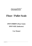
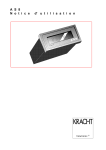
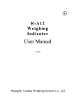
OPERATION
MANUAL
Edition
Month
st
1
2nd
3rd
4th
5th
October
June
year
2003
2004
1
Chapter 1
Main Specification
1. Analog:
Input Signal: 0 ~ 10mV
Converting Speed: 40 times/second
A/D code: 360000
Non-linearity: 0.03%
Drift: 0.03%
Stimulating Voltage: DC+5V
Load Cell: 1×350Ω
2. Display
Display: 0 ~ 999999
Interval: 1/2/5/10/20/50 (optional)
3. Serial Communication Interface (Optional)
Signal: RS232C
Transmission Distance: < 20m
4. Ambient Environment
Power Supply: AC 220v ( ~15% ~ +10% ); 50HZ (-2% ~ +2%)
Ambient Temperature: 0℃ ~40℃
Storing Temperature: -25℃ ~55℃
Ambient Temperature: ≤85%RH
Warm-up Time: 10~15minutes
Fuse: 500mA
6.
Weight: 2Kg
( excluding battery )
2
Chapter 2 Installation
2.1 Front and back view of the indicator
Front View of the Indicator
Back View of the Indicator
3
2.2 Connecting load cell to indicator
The 9 pin plug is for load cell , please connects the line as following graphs
End of Indicator
h +V
Shield
-V
c
h
d
i
+V
e
f
j
-IN
g
End of load cell
c-V
Stimulating Power Supply +
Stimulating Power Supply -
k
+IN
k+IN
j -IN
gShield
Signal Output+
Signal Output -
Connection of load cell
◆You must cut off power when connecting load cell, the connection must be reliable.
◆After connecting load cell, you should fasten plug with screw-driver.
◆Load cell and indicator are static sensitive devices, you must adopt anti-static measures
during operation. You must mount lightening rod in thunderstorm frequently happening
area.
2.3 Serial Communication Interface (Optional)
1. Indicator communicate with computer by serial communication interface .
2. Connection
Indicator communication interface adopts 5 pin plug, pin definition is as follows
5 pin ------TXD signal (serial communication data)
1 pin ------ ground line
2 pin ------ shield line
The communication interface is 2pin plug.
1 pin ---------signal (serial communication line)
2 pin ---------ground line for communication
3. Parameter
① Signal: RS232C
② Baud Rate: 1200/2400/4800/9600 (Ref. Chapter 4 Calibration)
③ Data format:=〈Weight data (including decimal)〉,ASCII Code
The low bit is prior to high bit and symbol. Negative symbol is”-“; Positive symbol is “0”.
For example: While indicator displays –500.00Kg, serial output is 00.005While indicator displays 500.00Kg, serial output is 00.0050
4
Chapter 3 Operation
3.1 Turning on
3.1.1 Turn on the power, the indicator performs self-checking and displays current voltage
of battery and go into weighing mode.
3.2
Operation
3.2.1
Press
for zero return, indicator returns to zero within the zero range 4%FS. To make
sure the stabilization light is on when zero operation.
3.2.2
At weighing mode, press
to deduct displaying weight while it is positive and
stabilization light is on. Indicator displays net weight “0”, tare light is on, press
deduct
to
tare , tare light is off, indicator displays gross weigh.
3.2.3
At weighing mode, press
to enlarge the resolution of weight to 10 times. Press
again to get back.
3.2.4
At weighing mode, press
to lock the weight value. Holding light is on. .The weight
value will be hold even if you take object off or put it on. Press
again to get back
.3.2.5 Manual accumulation
At weighing mode, while the weight value is large or equal to 20 counts and the value is
stable , press
to perform manual accumulation operation. Meanwhile, indicator first
shows the total accumulating times (two steps) :[n=] (that means the times displaying),
after 1 second later , it displays accumulating times [
****]; and then to display the total
value of accumulation (two step):[ totl =] (that means to display the total value of
accumulation), after 1 second later, it displays accumulating value [******], accumulating
light is on.
Note: the max. accumulation times are 99999 (under the condition of accumulating
amount ≤999999); Prior to the delete operation ,the accumulating amount is
recorded even power off .
5
3.2.6 Automatic accumulation
At weighing mode, press
+
together, indicator performs automatic accumulation,
and accumulating light flashes. At automatic accumulation mode, while the weight value is
large or equal to 20 counts and the value keeps stable for 1-2 seconds, indicator performs
one time automatic accumulation, displaying accumulation times and amount.
Note: The accumulating amount is not recorded under automatic accumulating
mode when power off.
3.2.7
At weighing mode, press
to delete the accumulation times and amount.
3.2.8 Kg/lb diversion
At weighing mode, press
+
together, indicator performs unit diversion; while the
unit is lb, the final decimal of the displaying value is lighted.
Note: once you operate accumulating and fail to delete the accumulation amount at one of
the unit, unit diverting is not allowed ,unless you delete the accumulation amount
3.2.9 preset tare
At weighing mode, press
+
together, indicator performs tare presetting.
The procedure is as follows:
Step
Operation
1
2
Press
3
display
Explanation
[ ****** ]
Weighing display
[P00000]
Remind to input preset tare
+
Input preset tare, eg “6000”
[
6000]
Press
6 times to change the
lowest digit to “6”, and then press
3 times to set the value as
“6000”, and press
4
[ ******]
Turn back to
displaying the
deducting tare
to confirm
weighing mode,
net weight of
3.2.10 Automatic dormancy
Indicator keeps at stable mode for 2 minutes and no any operating and weighing, it will
turn to automatic dormancy, meanwhile the final decimal is lighted. Any operating and
weighing will arouse it to working mode.
6
3.3 At calibration and preset tare mode, some of the keys perform as follows
1.
: perform “1” adding, press
2.
: perform moving, press
to move the lowest digit to left.
3
: perform inputting, press
to input setting value to the indicator
4
: perform exiting, press
to add “1” on the lowest digit .
to exit calibration
Chapter 4
Calibration
4.1 Turn on the indicator and connect load cell correctly . the indicator warms up for 15-30
minutes at “no load”
At weighing mode, press
+
together for calibration
4.2 Calibration steps
Step
Operation
1
2
Press
+
Display
[ ****** ]
Weighing display
[d
Setting of interval: indicator displays
the original interval, which can be
updated by operator
*]
Input updated interval
Eg: “1”
3
Press
once to change
Parameter range:1,2,5,10,20,50,
[d
1]
the value to “1”
Press
to confirm the updated
one is as same as the original one
[dP
*]
Input updated decimal
Eg: “3”
Press
Press
for confirmation
4
5
Explanation
three times to
[dP
3]
Decimal setting:
Indicator displays the original decimal
position, which can be updated by
operator.
Parameter range:0~5,
0 means no decimal,
1~5 separately means the decimal
position from 1~5
change the value to “3”
Press
Press
for confirmation
to confirm the updated
one is as same as the original one.
7
6
[F *****]
F.S setting: indicator displays the
original F.S,, which can be updated
by operator.
Input undated F.S.
Eg:”6000”
six
Press
7
times
change the value to “6”, and
then press
If there is no need for zero and F.S
to
[
6000]
calibration, press
to step 13,
otherwise you must input F.S value to
step 8 and 9.
three times
to move to “6000”, press
for confirmation
[ nloAd ]
8
[
LoAd]
9
Finish of weight loading,
Zero calibration: indicator self-checks
the zero position, provided indicator
didn’t calibrated zero before, it
displays the zero inner code,
otherwise it go to step 9
F.S calibration: Zero position is
confirmed, you can load weights for
the preparation of F.S calibration, that
should be >1/2 of the F.S
[ ******]
Indicator displays the inner code of
the loaded weight
[ ****** ]
At the stabilization of the value,
indicator will display the weight of
loaded weight
10
press
11
Input the actual weight of
loaded weight
Eg:”3000”
12
Press
[
3000]
Press
to step 13, if the inputted
weight is as same as the loaded
weight.
three times to
change the value to “3”, and
then
press
for
confirmation
[bt
*]
13
14
[ ****** ]
8
Baud rate: Indicator displays the
original baud rate parameter, which
can be updated by operator
Calibration is over, exit to weighing
mode
Chapter 5
Error Indication
ERRORO
The zero inner code is over 260000 when calibration.
ERROR1
The loaded inner code is less ; load cell capacity is more .
ERROR2
The loaded inner code is more ; load cell capacity is less.
ERROR 3
Calibration exceeding
HHHHHH
The zero lever is too high or load on the platform .
LLLLLLL
The zero lever is to high or no pan on the platform.
Chapter 6
Chargeable Battery
6.1 Turing on the AC power, the indicator will charge the battery automatically. So if you
don’t use battery frequently, you should take battery out.
Note: red end is +, black end is -. Wrong connection will destroy indicator.
Note: The built-in battery should be fully charged before it is used for the first time.
6.2 Only when you turn off the AC power, and push start key, battery works.
Displaying [LouoL] means the insufficient of voltage, it needs charge.
6.3 When you use the battery first time, you should charge the battery for 20 hours in
order to prevent low voltage resulted from the self leakage of the battery.
6.4 If you don’t use battery for a long time, you should charge the battery for 10-12 hours
for each 2 month to prolong using life of battery.
6.5 The battery is easily exhausted products. And it is not granted free guarantee.
9
Chapter 7
Maintenance
7.1 To guarantee indicator clarity and using life, the indicator shouldn’t be placed directly
under sunshine and should be set in the plain space.
7.2 The indicator can’t be placed into the place where the dust pollution and vibration are
serious.
7.3 Load cell should connect with indicator reliably, and the system should be well
connected into ground. The indicator must be protected from high electrical field and
high magnetic field.
◆In order to protect the operator, indicator and relevant device, you should mount
lightning rod in thunderstorm frequently happening area.
◆ Load cell and indicator are static sensitive device, you must adopt anti static
measures.
7.4 It is strictly forbidden to clean the case of indicator with intensive solvents (for example:
benzene and nitro oils)
7.5 Liquid and conducting particle should not be poured into the indicator, otherwise the
electronic components will be damaged and electric shock is likely to happen.
7.6 You should cut off power supply of indicator and relevant device before you pull-in and
out the connecting line of indicator and external device.
◆ You must cut off power supply of indicator, before pulling out connecting line of load
cell.
7.7 During operation, if trouble occurs, operator must pull off the power supply plug
immediately, and user should return this indicator to our company for repair.
Non-weighing manufacturer should not repair it, or by yourself, otherwise further
destruction may happen.
7.8 The storage is not granted the free repair guarantee, because it is easily exhausted
products.
◆In order to prolong using life, please charge the cell fully before using it. If you don’t use
the indicator for a long time, you must charge the cell every two month and for eight
hours/each charging time.
◆ Moving or installation must be carefully taken and must avoid strong vibration, impact
and bump in order to protect the storage cell from being damaged.
7.9 From invoice date, the indicator has a one-year free repair period. If any non-artificially
obstacle about the indicator happens under correct using conditions within this period,
the user is allowed to send the product with its guarantee card (of the correct number)
back to our corporation for free repair. The indicator shouldn’t be taken apart,
otherwise free guarantee will be cancelled.
10