1
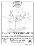
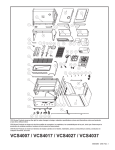
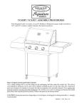
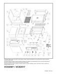
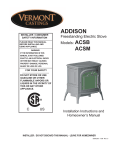
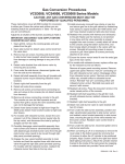
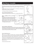
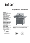
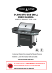
Model
VCS5007
Shown
USER’S MANUAL for Models
VCS5037
G as Barbecue Grill
(Propane & Natural Gas)
50004060 12/06 Rev.1 En
Warnings
DANGER
If you smell gas:
1. Shut off gas to the appliance;
2. Extinguish any open flame;
3. Open lid;
4. If odor continues, keep away from the appliance and immediately
call your gas supplier or your fire department.
WARNING
Do not store or use gasoline or other flammable liquids or vapors in the
vicinity of this or any other appliance.
An LP cylinder not connected for use shall not be stored in the vicinity of
this or any other appliance.
Always read and understand the WARNINGS and SAFETY
INSTRUCTIONS that are contained in this Manual before attempting to
use this Gas Barbecue Grill, to prevent possible bodily injury or property
damage.
Always keep this Manual in a safe place, for convenient future reference.
Never store flammable or easily combustible objects (matches, butane
lighters, cloths, etc.) in the pull out warming drawer (if equipped).
Page i
Warnings
SIGNAL WORDS:
The Signal Words used in this Manual, and their intended meanings, are as follows :
DANGER: Indicates that a failure to observe the safety instructions could result in death or
catastrophic bodily injury.
WARNING: Indicates that a failure to observe the safety instructions could result in serious
bodily injury.
CAUTION: Indicates that a failure to observe the safety instructions could result in property
damage or minor bodily injury.
NOTE: Designates important information relating to the safe use of the Grill.
IMPORTANT WARNINGS:
Since this outdoor cooking appliance is movable, is fueled by natural or propane gas, generates
very high temperatures for cooking and emits carbon monoxide as a by-product of combustion,
prudent precautions must be taken to assure its safe use.
DANGER: This Grill has been designed for OUTDOOR use only.
Never use this outdoor Grill inside any building, garage, shed or breezeway, or inside any boat,
trailer or recreational vehicle, to prevent a possible fire and to prevent the possibility of carbon
monoxide poisoning or asphyxiation
DANGER: Exposing an overfilled or a disconnected propane cylinder to heat could cause
venting of fuel through the pressure release valve. Since propane vapor is heavier than air it
tends to pool and, if ignited, could produce a violent fire or explosion.
Never install a propane cylinder if it is more than 80% full, as the contents may lack adequate
room for expansion when exposed to heat.
Never store a spare Propane Gas Cylinder in the cylinder compartment of this Grill, because it
will be exposed to high temperatures when the Grill is in use.
This Gas Barbecue Grill will provide you with many years of pleasure and enjoyment, if it is
used in accordance with the Warnings and Safety Instructions contained in this Manual.
The essential Warnings and Safety Instructions are located throughout the pages of this Manual,
but some of the principal ones have been summarized as follows for your convenience:
Page ii
Warnings
A. SAFE LOCATIONS FOR USE OF THIS OUTDOOR GRILL
DANGER:
Never use this outdoor Grill inside any building, garage, shed or breezeway, or inside any boat, trailer or
recreational vehicle, to prevent a possible fire and to prevent the possibility of carbon monoxide poisoning
or asphyxiation.
WARNINGS:
Always confirm that this Grill is not positioned under a combustible object (e.g., an awning or umbrella) or
in a covered area (e.g., a porch or gazebo) before lighting it, to prevent a possible fire.
Always confirm that this Grill is not positioned under the overhang of a house, a garage or other structure
before lighting it. An overhang will serve to deflect flare-ups and radiated heat into the structure itself, which
could result in a fire.
Always confirm that this Grill is positioned more than
36” (1 m) away from any combustible materials or
surfaces before lighting it, and that no gasoline or other
volatile substances are stored in the vicinity of this
Grill. The temperature of a grease fire or of the
radiated heat might otherwise be sufficient to ignite
nearby combustibles or volatile substances.
Always locate this Grill where there will be ample
combustion and ventilation air, but never position it in
the direct path of a strong wind.
Never allow the Grill to operate while unattended, to
prevent uncontrolled grease fires from erupting.
36”
(1
m)
1
”(
36
m
)
Never attempt to move this Grill while it is in operation
or while it is still hot, to prevent possible personal injury.
Never store or use gasoline or other flammable or
volatile substances inside or in the vicinity of this Grill
or in the vicinity of any other heat-generating
appliance, because of the danger of starting a fire.
Fig. 1
Always confirm that the installation of this Grill conforms with the requirements of all local Codes or, in the
absence of any applicable local Codes, with either the National Fuel Gas Code, ANSI Z223.1/NFPA54, or
CAN/CGA-B149.1-05, Natural Gas and Propane Installation Code.
Page iii
Warnings
B. SAFE USE OF LP (PROPANE) GAS
DANGER:
Never install a propane cylinder that is more than 80 % full, as the contents may lack adequate room for
expansion when exposed to heat. Propane vapor may then be vented through the pressure release valve,
which could accumulate in a pool and later result in a fire or explosion.
Always instruct your certified propane fuel supplier to confirm by weight that your cylinder is not more than
80 % full. An empty cylinder will weigh about 19 lb., while a properly filled cylinder should weigh no more
than 39 lb.
Never store a spare Propane Cylinder in the cylinder compartment of this Grill. Exposing a disconnected
cylinder to heat could result in the venting of propane vapor through the pressure release valve, and the
pooled vapor could result in a violent fire. (No hazard is posed by the connected cylinder if it is not
overfilled, however, as it tends to refrigerate itself while it is being used.)
Always confirm that all openings in the cylinder compartment of this Grill are free of any obstructions that
would restrict the circulation of ventilation air. Good ventilation will prevent the pooling of leaked propane
vapor, which is heavier than air, and which could explode if ignited.
WARNINGS:
Always consult the Rating Label on the back of the Grill to confirm which fuel must be used with the Grill.
Never operate the Grill with propane gas if it has been configured to use natural gas, to prevent hazardous
overheating.
Always confirm that there are no gas leaks before lighting this Grill. Apply a 50/50 solution of liquid soap
and water to the gas supply line connectors with a brush or spray bottle, and watch for bubbles. Never use a
match or open flame to test for gas leaks.
Always visually inspect the gas supply line for fraying, cracking or rodent damage before each use of this
Grill and, if necessary, install a replacement obtained from your dealer before lighting this Grill.
Always store your spare Propane Gas Cylinders in an outdoor area that is well-ventilated, shady, cool and
removed from any heat source. Always store those cylinders in an upright position. Never store a spare
cylinder in the vicinity of this Grill, or in the vicinity of any other heat-generating appliance.
C. SAFE USE OF NATURAL GAS
Always consult the Rating Label on the back of the Grill to confirm which fuel must be used with the Grill.
Never attempt to operate the Grill with natural gas if it has been configured to use propane gas, to prevent
possible bodily injury.
Always employ a qualified service agency to install all necessary gas supply plumbing, for safety reasons and
to assure compliance with all applicable Codes.
Page iv
Safety
Always promptly shut off the gas supply and immediately extinguish all flames if you smell gas. Always seek
assistance from your gas supplier or local Fire Department if the gas smell persists, because of the danger of
fire or explosion.
Always confirm that there are no gas leaks before lighting this Grill. Apply a 50/50 solution of liquid soap
and water to the gas supply line connectors with a brush or spray bottle, and watch for bubbles. Never use a
match or open flame to test for gas leaks.
Always visually inspect the gas supply line for fraying, cracking or rodent damage before each use of this
Grill and, if necessary, install a replacement before lighting this Grill.
Never permit a gas supply line to contact any heated surface of this Grill.
Ensure the Grill is properly cooled before placing the cover back on the Grill.
D. PREVENTION OF BURNS
Always keep children and pets under close supervision when using this Grill, and never permit them to come
near the Grill while it is in use, as the exterior surfaces will be very hot.
Always wear insulated protective mitts when working at the Grill, or when attempting to close a gas supply
valve after cooking has been completed, to prevent possible burns. Always use insulated pot holders when
handling containers of hot food.
Always wear an insulated protective mitt when adding a smoking agent to a Smoker Box.
Never store or use gasoline or other flammable or volatile substances in the vicinity of this Grill, or in the
vicinity of any other heat-generating appliance.
E. ELECTRICAL SAFETY
Always confirm that this Grill has been grounded in accordance with local Codes or, in the absence of local
Codes, with the National Electrical Code, ANSI/NFPA No. 70 or the Canadian Electrical Code, CSA C22.1,
when an external electrical source is being utilized for the Rotisserie Motor.
Always use a grounded three-prong outlet and a three-prong extension cord to energize the Rotisserie
Motor. Never alter or remove the grounding prong on the Rotisserie Power Cord, as an electric shock hazard
would then result.
Never permit an electrical supply cord to contact any heated surface of this Grill.
Page v
Safety
FUELS
WARNING: Never use Natural Gas in a Grill that has been configured to burn Propane Gas, and never use
Propane Gas in a Grill that has been configured to use Natural Gas, to avoid possible bodily injury. Always
consult the Rating Label on the back of your Grill to confirm which fuel must be used with the Grill.
WARNING: Use only the pressure regulator and type I propane gas supply coupling and hose that is
originally provided with this appliance or as specified, (see Fig. 2).
ADDITIONAL WARNINGS:
Always install a 20 lb. propane cylinder that is equipped with a
type I valve outlet (see Fig. 3), and that has a 12” diameter and
an 18” height. Always use a propane cylinder that has been
constructed and marked in conformance with either the
specifications for LP Gas Cylinders of the U.S. Department of
Transportation or the specifications in the National Standard
of Canada, CAN/CSA-B339, Cylinder, Spheres and Tube for
Transportation of Dangerous Goods, as applicable.
Check hose for breaks
or wear before each use.
Type 1
Connector
Always confirm that your propane cylinder is equipped with a
shutoff valve terminating in a Type I propane cylinder valve
outlet connection, and that it has been provided with a collar to
protect the cylinder valve.
Fig. 2
Regulator
Never install a propane cylinder in this Grill unless it is
equipped with a listed Overfill Protection Device (OPD).
Shutoff Valve
Always have a new propane cylinder properly purged of air by
your certified propane gas dealer. Since a new cylinder is
initially filled with air, the air must first be purged before it is
filled with propane.
Collar
Always visually inspect the gas supply line for fraying, cracking
or rodent damage before each use of this Grill and, if
necessary, install a replacement obtained from your dealer
prior to lighting this Grill.
Place dust cap on cylinder valve outlet whenever the cylinder is
not in use. Only install the type of dust cap on the cylinder
valve that is provided with the cylinder valve. Other types of
caps or plugs may result in leakage of propane.
Fig. 3
Page 2
Safety
DANGER:
a) Do not store a spare LP - Gas Cylinder under or near this appliance
b) Never fill the cylinder beyond 80% full; and
c) If the information in a) and b) is not followed exactly, a fire causing death or serious injury may occur.
WARNING: Always confirm that the openings in the cylinder compartment of the Grill are free of any
obstructions that would restrict the circulation of ventilation air. Good ventilation will prevent any possible
accumulation of leaked propane vapor, which is heavier than air and which could explode if ignited.
NOTE: Always have a certified propane gas supplier inspect and re-qualify your refillable propane gas cylinder
prior to each refilling, in accordance with DOT or TC requirements for propane cylinders.
ADDITIONAL WARNINGS:
Always handle propane cylinders with great care, as the contents are under high pressure.
Always close the propane cylinder valve promptly after each use of the Grill.
Always store propane cylinders outdoors, in an upright, secure position, out of direct sunlight, away from
living quarters and in a well-ventilated, cool, dry area. NEVER STORE A CYLINDER IN A BUILDING,
GARAGE OR OTHER STRUCTURE OR ENCLOSED AREA.
Always keep cylinders out of reach of children.
Always confirm that a valve dust cap has been tightly installed and that the valve itself is fully closed,
whenever a propane cylinder has been disconnected.
Always transport a propane cylinder in an upright, secure position, after confirming that its valve is closed.
Always stabilize a cylinder so that it cannot move, when it is being transported in a car trunk.
Never transport a propane cylinder in the passenger compartment of a car or truck.
Never store a Gas Grill indoors, unless the propane cylinder has first been disconnected and removed from
the Grill.
Never expose a propane cylinder to any heat source, never apply heat directly to a cylinder and never store a
spare cylinder in the vicinity of this Grill.
Never paint a propane cylinder a dark color, as this can cause the cylinder and its contents to overheat.
The LP cylinder must be arranged for vapor withdrawal. The cylinder must be upright with the valve at the
top. (Fig. 3)
Page 3
Gas Hookup
Hooking Up to the LP (Propane) Gas Supply
FOR YOUR SAFETY
1. WARNING: Never store or use gasoline or any
other volatile substance in the vicinity of this Grill.
2. WARNING: Never store a spare propane cylinder
in the vicinity of this Grill, or in the vicinity of any
other potential heat source.
LP (PROPANE) GAS SUPPLY CONNECTION
1. Always place the propane tank in the tank locator hole in
the bottom pan of the cylinder compartment and insure it
is secured into place.
2. Always confirm that all burner control knobs are in the
OFF position before activating the gas supply.
Fig. 4
3. Always connect the gas supply regulator as follows:
Insert the nipple of the valve coupling into the tank valve
and tighten the connection collar by turning it clockwise
with one hand while holding the regulator with the other
(see Fig. 4).
WARNING: Always conduct a leak test before lighting the
Grill, to prevent a possible fire or explosion (see page 5).
CAUTION: For connection of an LP gas grill to a fixed pipe
LP bulk system, consult your local gas supplier.
Fig. 5
Page 4
Gas Hookup
NATURAL GAS SUPPLY CONNECTION
TO CONNECT:
1. Push back the Sleeve on the Socket as shown below
(see Fig. 6a).
2. Insert Plug and release the Sleeve (see Fig. 6b).
3. Push the Plug until Sleeve snaps forward to lock the
Plug in the Socket.
Retract Sleeve
Fig. 6a
WARNING: Always conduct the following safety tests
before lighting the Grill, to prevent a possible fire or
explosion (see leak test below).
TO DISCONNECT:
1. Push Sleeve back and pull the Plug out.
Release Sleeve
Release
Sleeve
Fig. 6b
TESTING FOR GAS LEAKS (for LP and Natural Gas)
Before attempting to operate this Grill:
1. Always confirm that all burner control knobs are in the OFF position.
2. Always connect the gas supply hose first and then open the gas shutoff valve.
3. Always use a brush or spray bottle to apply a 50/50 solution of liquid soap and water to all connection points
(see Fig. 5) to test for gas leaks. Never use a match or open flame for that purpose.
4. Always look for bubbles to appear, as the appearance of bubbles will indicate a gas leak. Always turn off the
gas immediately and tighten the connection, if you find that a leak exists.
5. Always repeat this procedure until no further gas leaks are found to exist, before lighting the Grill.
6. Never attempt to light this Grill, however, if a leak cannot be stopped. Always call your gas supplier
promptly to obtain assistance.
WARNINGS:
Always consult the Rating Label on the back of the Grill to confirm that it has already been configured to
burn Natural Gas.
All gas supply plumbing should be performed only by a qualified service agency. In the U.S., the supply
connection must be made in accordance with local code or, in the absence of local codes, with the national
fuel gas codes, ANSI Z223.1/NFPA54. In Canada, the supply connection shall be carried out in accordance
with the provincial authorities having jurisdiction and in accordance with the requirements of the CAN/
CGA 1-B149.1 installation code. A shutoff value must be installed between the gas grill and the main supply.
For natural gas, use a 3/8” or 1/2” natural gas supply line capable of an a input of up to 100,000 BTUs
(depending on the model).
Always disconnect the Grill and close its individual manual shutoff valve, when conducting pressure tests of
the gas supply piping system at pressures which exceed 1/2 psi (3.5 kPa).
Always isolate the Grill from the gas supply piping system by closing its individual manual shutoff valve.
Page 5
Operation
CONTROL FUNCTIONS
PROPANE TANK VALVE
WARNING: Never open the Tank Valve unless the Grill is being prepared for use, to prevent the pooling of
propane vapor.
Always open the Valve immediately before lighting the Grill, and always close it immediately after cooking has
been completed.
BURNER CONTROL VALVES (see Fig. 7)
On Models VCS3507, VCS3517 & VCS3507BI, there are three independent control valves for the main
burners, and a separate control valve for the rotisserie burner (if equipped).
On Models VCS4007, VCS4017, VCS4027, & VCS4037, there are four independent control valves for the
main burners, and a separate control valve for the rotisserie burner.
On Models VCS5007, VCS5017, VCS5027, VCS5037, & VCS5007BI, there are five independent control
valves for the main burners, and a separate control valve for the rotisserie burner.
The OFF position is indicated above each knob. A full range of flame adjustment is available from High to
Low, (by turning a knob counterclockwise).
ACTIVATING THE IGNITER
ELECTRONIC IGNITION SYSTEM
As you push and hold the Igniter Button, you will hear a series of clicks as the igniter module generates an
ignition spark to the burners. The burner should light within five seconds. Depending on which model you
have, the system is powered by either a single “AA” or a single “AAA” battery. Ensure the battery has been
installed before using the igniter. To remove or replace the battery, turn the push button knob counterclockwise, and carefully pull out the spring and battery. Ensure that the positive end of the battery is in the
down (bottom) position before replacing the knob.
PIEZO IGNITION SYSTEM (if equipped)
As you turn the Igniter Knob clockwise, you will hear a click as the Piezo module generates an ignition spark to
the burner. Rotate the Igniter Knob until the burner lights. The burner should light within five seconds.
Igniter Button
(All Models)
(VCS5007 Model Shown)
Main Burners
(3, 4, or 5)
Rotisserie Burner Control
(if equipped)
Page 6
Fig. 7
Operation
NOTE: When lighting the grill for the first time,
burn with the main burners on HIGH for at least 30
1. a. Always open the Hood completely and always inspect the Grill minutes, to burn off any manufacturing residues.
LIGHTING THE MAIN BURNERS
and burners to confirm that all components are properly positioned
before lighting the main burners.
b. Make sure the grease cup is empty and grease tray is clean.
c. Always visually inspect the gas supply line for fraying, cracking, or
rodent damage before lighting the grill and, if necessary, install a
replacement obtained from your dealer prior to lighting the grill.
WARNING: Never stand with your head directly over the Grill
when preparing to light the main burners, to prevent possible
bodily injury.
2. Always confirm that all of the burner control knobs are in the OFF
position before opening the gas supply.
3. Turn on the propane gas supply valve at the tank (1 to 2 turns) or
turn on the main natural gas supply valve (see Fig. 8).
Fig. 8
4. Turn the selected Burner Control Knob to the HIGH position by
pushing down on the knob and turning it counter-clockwise.
5. Immediately activate the Igniter (see Page 6). The selected burner should light within five seconds. Light the
burners sequentially from either left to right or right to left.
WARNING: IF THE SELECTED BURNER DOES NOT LIGHT, immediately turn the burner control
knob to the OFF position, to prevent gas buildup. Wait five (5) minutes for the gas to clear and then repeat the
preceding starting procedure. If the burner will not light when using the Igniter, follow the match lighting
instructions (see Page 8).
6. Confirm that the burner is properly lit and that the flame pattern is as desired, (see Figs. 9a, 9b & 9c, for the proper
flame patterns). If the flame pattern is other than normal, consult the Troubleshooting Guide on Page 23 for
corrective action.
7. Always preheat the grill before starting cooking. Light all burners and adjust them to the HIGH position for 5 to
10 minutes or until the Grill reaches the desired cooking temperature. Before placing any food on the Grill, make
sure that the cooking surface is free from food and debris.
8. Adjust the Controls to a medium setting for most cooking requirements. A light coating of cooking oil on
the cooking grids, before heating the Grill, will help prevent foods from sticking to the Grill.
Fig. 9a
Normal: Soft blue flames
Fig. 9c
Fig. 9b
Out of Adjustment: Noisy, hard blue
flames indicate too much air
Page 7
Poor Combustion: Wavy yellow
flames indicate too little air.
Operation
TURNING THE BURNERS OFF
1. Always turn the burner control knob(s) to the OFF position when cooking has been completed.
2. Promptly turn OFF the gas supply valve at the propane cylinder or at the main natural gas supply line.
3. Close the Hood of the Grill.
FLARE-UPS
“Flare-ups” sometimes occur when food drippings fall onto the hot sear plates or burners and ignite. Some
flaring is normal and desirable, as it helps impart the unique flavors associated with grilled foods.
Controlling the intensity of the flare-ups is also desirable, however, in order to avoid burned or unevenly
cooked foods and to prevent the possibility of an accidental fire.
WARNING: Always monitor the Grill carefully while cooking and turn the flame level down (LOW), or
OFF, if flare-ups intensify. To prevent uncontrolled grease fires from erupting, never allow the grill to
operate while unattended.
MATCH LIGHTING THE MAIN BURNERS:
1. a. Always open the Hood completely and always
inspect the Grill and burners to confirm that all
components are properly positioned before lighting
the main burners.
b. Make sure the grease cup is empty and grease tray is
clean.
c. Always visually inspect the gas supply line for
fraying, cracking, or rodent damage before lighting
the grill and, if necessary, install a replacement
obtained from your dealer prior to lighting the grill.
WARNING: Never stand with your head directly over
the Grill when preparing to light the main burners, to
prevent possible bodily injury.
2. Always confirm that all of the burner control knobs
are in the OFF position before opening the gas
supply.
Fig. 10
3. Always turn on the propane gas supply valve at the tank (1 to 2 turns) or turn on the main natural gas supply
valve.
4. Insert a lit match or a butane lighter into the match lighting hole located on the left hand side of the base, (see
Fig. 10).
5. Turn the left Burner Control Knob to the HIGH position by pushing down on the knob and turning it
counterclockwise.
6. Never store flammable or easily combustible objects (matches, butane lighters, cloths, etc.) in the pull out
warming drawer (if equipped).
Page 8
Operation
LIGHTING THE ROTISSERIE BURNER (if equipped)
The Rotisserie burner provides the steady, even heat required to cook poultry and roasts to self-basted
perfection.
TO START THE ROTISSERIE BURNER:
1. Always open the Hood completely before attempting to light the Grill.
WARNING: Never stand with your head directly over the Grill when preparing to light the Rotisserie
burner, to prevent possible bodily injury.
2. Always confirm that all of the burner control knobs are in the OFF position before opening the gas supply.
3. Turn on the propane gas supply valve at the tank (1 to 2 turns) or turn on the main natural gas supply valve.
4. Turn the Rotisserie Burner Control Knob to the HIGH position, by pushing down on the knob and turning
it counterclockwise.
5. Immediately push the Igniter Button. The Rotisserie burner should light within five seconds.
WARNING: IF THE ROTISSERIE BURNER DOES NOT LIGHT, immediately turn the burner
control knob to the OFF position, to prevent gas buildup Wait five (5) minutes for the gas to clear and then
repeat the preceding starting procedure. If the burner will not light when using the Igniter, follow the match
lighting instructions below.
6. Confirm that the burner is properly lit and that the flame pattern is as desired, (see Figs. 9a, 9b & 9c, for the
proper flame patterns). If the flame pattern is other than normal, consult the Troubleshooting Guide on
Page 22 for corrective action.
7. Always preheat the Grill before starting to cook on the rotisserie.
8. Never operate the main burner when the rotisserie burner is on.
MATCH LIGHTING THE ROTISSERIE BURNER:
1. Always open the Hood completely, before attempting to light the Grill.
WARNING: Never stand with your head directly over the Grill
when preparing to light the Rotisserie Burner, to prevent possible
bodily injury.
Rotisserie
Lighting Hole
2. Always confirm that all of the burner control knobs are in
the OFF position before opening the gas supply.
3. Turn on the propane gas supply valve at the tank (1 to 2
turns) or turn on the main natural gas supply valve.
4. Insert a lit match or a butane lighter into the match lighting
hole located below the rotisserie screen (see Fig. 11).
5. Turn the Rotisserie Control Knob to the HIGH position by pushing
down on the knob and turning it counterclockwise.
Page 9
Fig. 11
Operation
ROTISSERIE SETUP (if equipped)
The Rotisserie burner is intended to be used for rotisserie cooking only.
WARNING: Never use the main burners while using the Rotisserie burner, as that could result in igniting the
drippings, or overheating your Grill, which could result in damage of the Grill.
The Rotisserie assembly includes a
counter-weight for large or irregular
food items ; using the counterweight
will reduce the strain on the motor.
1. Remove the warming rack. Lay a flat
pan directly on the cooking grates to
catch drippings. Large food items
may require that you remove the
middle cooking grate(s), and place
the pan on the sear plates.
Fig. 12a
Rotisserie
forks
Bushing
Rotisserie
support
Rotisserie
motor
2. Insert the ends of the Rotisserie
Support into the slots of the right
cooking grate, so that the edge of the
support is approximately 1” from the
right casting, and the top groove is in
line with the rotisserie spit hole in the
left casting (see Fig. 12a).
Motor
bracket
3. Engage the Motor Bracket to the left side of the base as
per Rotisserie instructions.
Spit Rod - Motor End
4. Engage the Rotisserie Motor in the Motor Bracket (see
Fig. 12a).
5. Assemble the spit and meat forks. Adjust the retainer
bushing to keep the spit in place (see Fig. 12a).
Fig. 12b
6. Tighten the thumbscrews with small pliers.
7. Insert the Spit Rod into the Rotisserie Motor (see Fig. 12b).
NOTES: Always use the counterweight to balance the spit when cooking large or irregular food items.
The Rotisserie Motor is rated to turn a maximum load of 12 lb.
WARNINGS:
Never use the Rotisserie Motor in the rain, and never use it if it has become wet.
Always use a grounded three-prong outlet and a three-prong extension cord to energize the Rotisserie
Motor. Never alter or remove the grounding prong on the Rotisserie Power Cord, as an electric shock hazard
would then result.
Never permit an electrical supply cord or a gas supply line to contact any heated surface of this Grill.
Page 10
Operation
LIGHTING THE SIDE BURNER (if equipped)
WARNING: Never stand with your head directly over the Grill when preparing to light the side burner, to
prevent possible bodily injury.
1. Turn the side burner control knob to HIGH (see Fig. 13).
2. Turn the Igniter Knob clockwise until the burner ignites. The burner should light within four clicks of the
igniter. NOTE: Some models are equipped with an electronic ignter. Refer to page 6 for respective piezo
and electronic igniter systems.
NOTE: Observe the flame pattern. Soft blue flames are normal ; hard blue flames or wavy yellow flames are
not. You can adjust the flame with the air shutter below the control knob (see Fig 19). If yellow flames persist,
refer to the Troubleshooting Guide on Page 22.
SHUTTING THE BURNER OFF
1. Turn the control knob counterclockwise to the HIGH position, then depress it and turn it to OFF.
NEVER force the knob without depressing it, as that can damage the valve.
NOTE: Single burner
model shown.
Fig. 13
Control
knob
Igniter
Page 11
Troubleshooting Guide
Burner will not
light
ACTION REQUIRED
POTENTIAL CAUSE
PROBLEM
Gas supply turned off
Turn on fuel supply and retry.
Out of propane
Confirm the flow of gas by smell or by listening
for the hiss of gas being emitted. Allow gas to clear
before attempting to relight.
Weigh your propane cylinder. A standard 20 lb.
cylinder will weigh about 19 lb. when it is empty
and 39 lb. when it is 80 % full.
WARNING: Never take a propane cylinder
indoors for any purpose.
Confirm that the venturi tubes are not blocked by
insects or other debris. Use a special venturi brush
to clean (Fig. 15).
Blockage in the gas system
Use a pin or needle to carefully probe the orifice in
the gas valve. Never enlarge the orifice (Fig. 16).
Misalignment of the gas valve to the
venturi tubes of the burner.
Look under the front control panel and reinsert the
gas injector into the venturi tube, if required (Fig.
22).
Improper attachment of the propane
hose and regulator
Tighten the regulator’s plastic collar onto the
cylinder valve.
Hand-tighten only (Fig. 4).
Unit won’t heat
up (LP)
Control knob left open at startup,
or
turning gas on too quickly
For safety, the regulator coupling on your barbecue
is equipped with a flow control mechanism. This
device limits gas flow in the event of a sudden
change in the demand for gas. This may be
engaged inadvertently, if a burner control knob
should be left ON when you open the propane
cylinder valve. Rapidly opening the valve can also
engage flow control. To resolve the problem, close
your cylinder valve. Confirm that all burner control
knobs are in the OFF position. Open the cylinder
valve slowly (about 1 to 2 turns) and wait 5
seconds. Finally, turn a single burner ON and try
relighting it.
Unit won’t stay lit
Wind
Always shelter your Grill from strong winds.
Running out of fuel
Confirm the flow of gas by smell, or by listening
for the hiss of gas being emitted.
Weigh your propane cylinder. A standard 20 lb.
cylinder will with about 19 lb. when it is empty ad
39 lb. when it is 80% full.
WARNING: Never take a propane cylinder
indoors for any purpose.
Page 22
Troubleshooting Guide
PROBLEM
Uneven burn
pattern
or
Flashback fire
ACTION REQUIRED
POTENTIAL CAUSE
Blockage in the burner or gas system
Confirm that the venturi tubes are not blocked by
insects or other debris. Use a special venturi brush
to clean (Fig. 15).
Use a pin or needle to probe the orifice in the gas
valve. Never enlarge the orifice (Fig. 16).
Use a small nail or toothpick to clean the burner
ports (Fig. 16).
Corroded burner
Corrosion of a gas burner can cause the solid
material between the gas ports to deteriorate,
resulting in uneven burning. See your retailer for
the appropriate replacement burner.
Excessive yellow
flame
Improper air shutter opening
Your Grill should burn with a predominantly blue
flame. If the flame is mostly yellow, check the
venturi tubes for obstruction and clean as shown
on Page 19. If yellow flames still persist, adjust the
opening on the air shutter of the venturi tube
located under the front console of the Grill (Fig.
20).
Flare-up
Excessively fatty foods
Trim all excess fat from meat before cooking.
Grease buildup
Confirm that the sear plate is clean and properly
installed. Remove excess grease from the burn
chamber.
Electrode fouled
Wipe the electrode with a soft, clean cloth.
Electrode improperly gapped
The electrode should be located 1/8” to 3/16”
from the burner, and positioned to spark to the
edge of a gas port. If the gap is incorrect, or the
unit is not properly sparking, gently bend the
electrode tip into position. Use caution so that the
ceramic insulator does not crack.
Electrode cracked
If the ceramic insulator on the electrode is cracked,
it may short out. Replace the electrode.
Lead wire is disconnected
Confirm that the lead from the Ignitor module to
the electrode is well seated on the termination of
the module.
Lead wire is cracked
A crack in the lead wire may result in shorting.
Replace the wire.
Battery dead or installed wrong
The battery in the Igniter Button may be dead or
installed incorrectly. Correct position is positive
end down.
Igniter does not
spark
Page 23
VCS4007 / VCS4017 / VCS4027 / VCS4037
VCS5007 / VCS5017 / VCS5027 / VCS5037
ASSEMBLY PROCEDURES
Tools Required: knife or scissors, Phillips or Robertson (square head) screwdriver..
Model VCS4007
Shown
Step 1: Unpack Carton and Verify Contents
Use a sharp cutting tool to cut the straps on the packaging and then lift off the carton top. The sleeve
surrounding the barbecue can be removed by lifting it straight up and over the top of the unit. Compare
all contents to the parts list that accompanies this assembly manual. Next, remove the protective plastic
coverings from the metal parts. Be careful not to scratch or damage the finish of the metal parts when
removing the protective plastic. Refer to the parts list for fastener detail.
CAUTION: Some parts may have sharp edges; to avoid injury, wearing gloves during assembly is
strongly recommended
Page 1
50004062 11/06 Rev.0 En
VCS4007 / VCS4017 / VCS4027 / VCS4037 / VCS5007 / VCS5017 / VCS5027 / VCS5037 Assembly
Step 2: Install the Casters
Parts Required: (4) Casters, (1) Block (not included)
Note: Casters (wheels) may differ from those shown in
the illustration depending on the model you purchased.
Select a side to begin installing the casters. Place a block
of wood, a telephone book or anything else available approximately 6 inches thick -under the side to support
the weight of the barbecue. Next, insert the pin on the top
of the caster into their respective holes located on the
bottom, near the front and rear corners. If you have any
difficulty snapping them into place, try rocking the
castors in a circular motion. When both casters are in
place, repeat the same procedure on the opposite side.
6” - 8”
(152 - 203mm)
Fig. 2
Step 3: Install U-Clip Fasteners
Parts Required:
(4) #10-20 U-Clip Fasteners
(1) Left Side Shelf Support, (1) Left Side Shelf
(1) Right Side Shelf Support, (1) Right Side Shelf
Install the one (1) U-Clip fastener to each of the Side
Shelf Supports as shown in Fig. 3a. One (1) U-Clip
should be placed on each bracket, with the flat side
down.
Fig. 3a
Install the one (1) U-Clip fastener to each of the Side
Shelves as shown in Fig. 3b. One (1) U-Clip should be
placed on the under side of each shelf, at the front
outside corner, with the flat side out.
FR
Fig. 3b
ON
T
Page 2
VCS4007 / VCS4017 / VCS4027 / VCS4037 / VCS5007 / VCS5017 / VCS5027 / VCS5037 Assembly
Slide
Parts Required:
(1) Left Side Shelf Support
(1) Left Condiment Tray
(1) Right Side Shelf Support
(1) Right Condiment Tray
(8) 1/4-20 x 1-1/2“ Bolts
Push
Step 4: Install the Side Shelf Supports
Bolts
Bolts
Note: Only the right side assembly is shown in Fig. 4a
and Fig. 4b. To install Left Side Support and Condiment
Tray, repeat this step for the left side.
On the right side of the barbecue there are four threaded
inserts, screw a bolt half way into each of the four
threaded inserts. You will notice the bottom slot of the
support has a 'Y' shaped slot and a 'keyhole' shaped hole
above it. Take the Right Side Shelf Support and slide the
top screw into the 'keyhole' and the bottom screw into the
opening of the 'Y' shaped slot. Now take the Right
Condiment Tray and align its holes over the two front
bolts and gently push down until the bolts settle into the
grooves of the tray.
Fig. 4a
Next: Gently push down on the support until the screw
settles into the top of the groove. Do not fully tighten the
support screws at this point.
Fig. 4b
Step 5: Attach Shelves
Then Snap
Into Place
Parts Required:
(1) Right Shelf - S/B (Shown)
(1) Left Shelf - Solid
Place the Right Shelf - S/B (shown) on top of the
supports making sure the holes are aligned and then snap
into place on the supports. The inside lip of the shelf will
slide between the grill shell and the shelf supports.
Slide End
On First
Fig. 5
Page 3
VCS4007 / VCS4017 / VCS4027 / VCS4037 / VCS5007 / VCS5017 / VCS5027 / VCS5037 Assembly
Step 6: Secure Shelves
Fig. 6
Parts Required:
(4) 10-24 x 1/2” Bolts (black)
A. Secure each Shelf by inserting (2) 10-24 x 1/2” bolts
through the U-Clip fasteners as shown in the diagram.
B. Tighten the four (4) Shelf Support bolts from Step 4 to
secure the shelf supports to the grill body.
A.
Insert
Bolts
Repeat Steps 5 & 6 for the opposite side of the grill.
B.
Tighten
Bolts
Step 7: Secure Side Shelf to Grill
Parts Required:
(3) 10-24 x 1/2” Bolts (black)
Bolt “a”
Bolt “b”
Lift the grill lid and insert two (2) #10-24 x 1/2” bolts,
shown as “a” and “b” in Fig. 7, to further secure the
Shelf Right - S/B to the grill body. Be sure to fully
tighten the bolts before proceeding to the next step.
Next: Repeat Step 7 on the opposite side of the grill’s
interior to secure the Shelf Left - Solid to the grill body
by inserting only one (1) #10-24 x 1/2” bolt in the “b”
location as shown in the illustration.
Fig. 7
Step 8: Secure Condiment Tray to Console
Parts Required:
(2) #10-24 x 1/2” Bolts (stainless)
(2) #10-24 Nuts (black)
Secure the Left Condiment Tray to the Console using a
#10-24 x 1/2” stainless bolt and a #10-24 nut. Make sure
the holes of the Condiment Tray and the Console are
aligned. Reach underneath the console and hold the nut
in place with one finger and insert the bolt from the
outside as shown in Fig. 8 and tighten until they are
securely fastened.
Next: Repeat Step 5 to secure the Right Condiment Tray
to the opposite side of the console.
Page 4
Bolt
Nut
Fig. 8
VCS4007 / VCS4017 / VCS4027 / VCS4037 / VCS5007 / VCS5017 / VCS5027 / VCS5037 Assembly
Step 9: Attach Side Burner Lid (S/B-Single)
Parts Required:
(1) Side Burner Lid (S/B-Single)
(2) #10-24 x 3/4” ( 1/4” Shank)*
* Included with the Side Burner Kit
Bolts
Attach the lid marked (S/B-Single) to the Shelf Right top
marked VM-S/B using two #10-24 x 3/4” ( 1/4” Shank)
bolts. Align the holes at the back sides of the lid with the
holes located in the shelf top and insert a bolt in each.
Note: If your unit is equipped with a side burner, please
refer to the instruction sheet included with the side
burner for installation instructions.
Fig. 9
Step 10: Attach Knobs
Parts Required:
VCS4007: (5) Knobs
VCS4017: (5) Knobs
VCS4027: (5) Knobs
VCS4037: (5) Knobs
VCS5007: (6) Knobs
VCS5017: (6) Knobs
VCS5027: (6) Knobs
VCS5037: (6) Knobs
Note: Depending upon your specific model, your grill
may require 5 or 6 knobs. Models VCS4007, VCS4017,
VCS4027, & VCS4037 are equipped with five (5) knobs,
and models VCS5007, VCS5017, VCS5027 & VCS5037
are equipped with six (6) knobs.
Fig. 10
Align the knobs on the valve stems and push inward until
the knob sits snugly on the stem.
Fig. 11
Step 11: Remove the Packing Tape
Remove the Packing Tape from:
The Grease Cup
The Base Assembly (inside the grill)
The Warming Rack
Note: For models VCS5007, VCS5017, VCS5027 &
VCS5037, remove the Packing Tape from the front pullout drawer.
Page 5
VCS4007 / VCS4017 / VCS4027 / VCS4037 / VCS5007 / VCS5017 / VCS5027 / VCS5037 Assembly
Step 12: Attach the Handle to the Door
Parts Required:
VCS4007/VCS4017/VCS4027/VCS4037: (1) Handle
VCS5007/VCS5017/VCS5027/VCS5037: (3) Handles
Note: Handles may not appear exactly as shown in
diagram
Attach the Door handle(s) to the door(s) by aligning the
handles over the holes and inserting the screws that were
supplied with the handles through the door panel and into
the handles. For models VCS5007,VCS5017,VCS5027
& VCS5037, attach the drawer handle using the same
method.
Note: If doors are not aligned or have shifted during
shipping, they can be adjusted by loosening the screws
which fasten the hinge of the door to the grill body and
shifting the doors until they are aligned. Once satisfied
with alignment, fully tighten the screws to secure the
doors into position.
Step 13: Install the Grease Cup and Grease Pan
Parts Required:
(1) Grease Cup
(1) Grease Pan
Install the Grease Cup into the cut-out in the Upper Base
Panel located underneath the grill. It is accessible from
the back of the grill. Once the Grease cup is in place,
move the Grease pan into position above it by placing
the side edges onto the support rails and sliding it into
place.
Fig. 13
Note: Make sure the funnel opening of the grease pan is
positioned over the Grease Cup.
Step 14: Attach Stabilizer Bracket
Parts Required:
(2) #10-24 x 1/2” Bolts (black)
(1) Stabilizer Bracket
Attach the Stabilizer Bracket underneath the bottom
panel by aligning the holes and inserting both #10-24 x
1/2” bolts through the panel and into the Stabilizer
Bracket as shown in Fig. 14.
Page 6
Stabilizer Bracket
Fig. 14
VCS4007 / VCS4017 / VCS4027 / VCS4037 / VCS5007 / VCS5017 / VCS5027 / VCS5037 Assembly
Step 15: Install the Internal Components
Parts Required:
VCS4007 / VCS4017 :
VCS4027 / VCS4037
(4) Sear Plates
(3) Cooking Grates
(1) Warming Rack
VCS5007 / VCS5017 :
VCS5027 / VCS5037
(5) Sear Plates
(4) Cooking Grates
(1) Warming Rack
Carefully place each of the Sear plates side by side inside
the barbecue, making sure the semicircular finger groove
is facing toward the front of the grill. Each sear plate
rests just above each burner tube.
Next, set the cooking grates, side by side, on the upper
ledge of the grill tub. Make sure the finger groove is
facing toward the front of the grill.
Burner
Sear Plate
Fig. 15a
Warming
Rack
Set the warming rack into the supports located on either
side of the rear lid.
Note: One side of the Grate surface has a rounded side
suitable for meats and a flat side suitable for delicate
foods (i.e. fish). Grates can be turned over according to
your preference.
Caution: Do not attempt to turn Cooking Grate over
while the Grill is in use and grates are hot. Doing so
could result in severe burns and other injuries.
Cooking
Grates
Fig. 15b
Step 16: Install the Battery
Note: requires a “AA” Battery.
Unscrew the Ignition Button from the console and insert
a battery into the housing by placing the positive side of
the battery in first. Then screw the Ignition button back
into the console.
Fig. 16
Page 7
VCS4007 / VCS4017 / VCS4027 / VCS4037 / VCS5007 / VCS5017 / VCS5027 / VCS5037 Assembly
Step 17: Install the LP Cylinder (LP Models Only)
Parts Required:
(1) LP Gas Cylinder (not included)
Note: Check your user’s manual for the cylinder filling
requirements, how to attach the regulator and how to test
for leaks before you try lighting the grill.
Caution: Make sure the hose is not touching any hot
surfaces.
Note: For Models VCS5007, VCS5017, VCS5027 &
VCS5037, refer to Tank Pull-out assembly instructions
included with the Tank Pull-out kit.
Fig. 17a
Place the LP Cylinder into the hole in the bottom panel.
Next secure it from moving by lifting the Cylinder
retainer wire and latching the bent edge over the lip of
the Cylinder. The final step is to connect the Regulator to
the Cylinder.
Caution: Do not turn on the grill until after performing a
leak check at all connection points and fittings. Use a
spray solution of 50% dish soap and 50% water onto all
connection points and fittings. Formation of bubbles
indicates air leaks.
Note: Ensure all plastic coatings have been removed
from all stainless steel parts before using the grill.
Fig. 17b
CFM Corporation
410 Admiral Boulevard
Mississauga, Ontario L5T 2N6 Canada
(800) 668-5323
www.cfmcorp.com
Service Note: If you are experiencing difficulties or are dissatisfied with your purchase, please contact CFM at
the telephone number listed above prior to returning your grill to the store.
Page 8
CFM Corporation
410 Admiral Boulevard
Mississauga, Ontario L5T 2N6 Canada
(800) 668-5323
www.cfmcorp.com
Service Note: If you are experiencing difficulties or are dissatisfied with your purchase, please contact CFM at
the telephone number listed above prior to returning your grill to the store.
Page 12