1
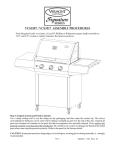
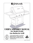
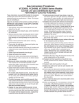
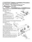
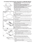
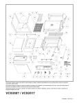
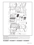
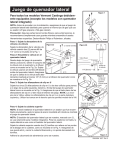
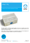
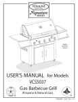
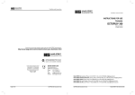
Side Burner Assembly
Kit No. VCS35SB
For all properly equipped Vermont Castings Models (except Built-In models)
Note: Before proceeding with the installation, make sure this side burner kit is
designed to burn the same type of gas as your grill (LP-Propane or NG-Natural
Gas).
Fig. 1
Caution: Some parts may have sharp edges; to avoid injury, wearing gloves
during assembly is strongly recommended.
Tools Required: Philips or Robertson Screwdriver, pliers.
Step 1:Attach Valve Bracket to Valve
Attach the valve bracket to the valve with (2) #6 x 1/4” Bolts as shown in Fig. 1.
Step 2: Assemble the Valve to the Side
Burner
From under the side burner assembly, position
and align the valve assembly to the burner and
venturi as shown in Fig. 2a. Fasten the valve
using (2) #8 screws from the top of the side
burner. Ensure the valve outlet is properly
inserted into the burner venturi a minimum of
1/4” [6mm] as shown in Fig. 2b.
B. Insert Screws
Fig. 2b
Venturi
Tube
A. Insert Valve
Valve
Outlet
1/4” [6mm]
Fig. 2a
Fig. 3
Step 3:Attach the U-Clip Fasteners
Attach the (3) U-Clip fasteners to the three bolt hole locations along the left and
front of the side burner assembly as shown in Fig. 3. Make sure the flat side of the
U-Clip fasteners are facing the inside of the assembly. Do not attach U-Clip
fasteners to the right side of the side burner assembly.
Step 4:Attach the Top Cover
Note: If you are installing a side burner onto a previously assembled grill,
remove the stainless shelf insert where the side burner assembly will be mounted.
CA
UT
IO
N
Note: The side burner frame that is shown, marked with (*), is used for built-in
models only. For standard grills, the side shelf is used as the side burner frame.
Attach the top cover using (2) shoulder screws at the hinge points of the cover as
shown in Fig. 4. Be sure the top cover can open and close freely - do not over
tighten the screws.
Attach caution sticker as shown.
*
Fig. 4
Side Burner Assembly
Step 5: Assemble the Side Burner to the
Side Shelf Frame
Position the side burner assembly (from the
bottom) into the side shelf frame as shown in
Fig. 5a. Make sure the side burner flanges are
outside of the frame flanges. Fasten the
assembly using (3) #8 x 1/2” bolts into the UClip fasteners along the left side and front. Use
(2) #8 x 1/2” bolts and nuts on the right side
(Fig. 5b). Tighten the bolts securely.
Fig. 5a
Fig. 5b
Bolts
Bolts
Step 6: Install the Knob, Cooking Grate
Attach the valve control knob to the valve
stem as shown in Fig. 6a.
Set the cooking grate over the burner as shown
in Fig. 6b.
Fig. 6a
Fig. 6b
Step 7:Attach Connector Hose to the Grill
Remove the knock out slug from the top front corner of the right cabinet side
panel, And insert the plastic “snap” bushing. Position the end of the side burner
hose through the bushing, into the base cabinet. Connect the end of the hose to the
gas supply by snapping it into the female quick connect fitting provided at the tee
of the gas pressure regulator (LP models), or the gas supply line (natural gas
models). This is accomplished by pulling back the outer ring of the female
coupling, inserting the male fitting of the hose fully, then releasing the ring. The
hose should be positively engaged.
Step 8: Leak Check
Turn on the gas at the cylinder (LP models) or main valve (natural models). DO
NOT turn the side burner valve on. Perform a leak check at all connections and
fittings, by brushing or spraying a 50/50 solution of dish soap and water. If any
bubbles appear, correct the leak before attempting to light the side burner or the
grill. Refer to the User’s Manual for lighting and use instructions.
Fig. 7
Replacement Parts:
Igniter and Knob
Valve Knob
Burner
Grate - Cast
Grate - Wire
50000367
50000113
50001044
50001035
50003050
Hose Assembly
Valve-Nat Gas
Valve-LP
Electrode
50001092
50001045
50001046
50000115
50003564 11/06 Rev 1
CFM Corporation
410 Admiral Boulevard
Mississauga, Ontario L5T 2N6 Canada
(800) 668-5323
www.cfmcorp.com