1
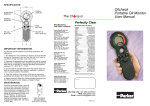
UBS OFFLINE
USER MANUAL
ENGLISH VERSION
P.899307
© Parker Hannifin (UK) Ltd, 2006
www.parker.com/cmc
Email: [email protected]
*****BLANK PAGE*****
CONTENTS
SECTION
PAGE
Introduction
3
1. The effect of system conditions
4
2. Fluid sample extraction
5
3. Sample handling and preparation
6-8
4. Operating Instructions
4.1 Primary connections
8
4.2 Inserting bottles
9
4.3 Running the test
9/10
4.4 Testing a new sample or
finish testing
11
4.5 peristaltic pump operation
11
5. Pumphead tube fitting (or replacement)
12
1
UBS OFFLINE
*****BLANK PAGE*****
UBS OFFLINE
INTRODUCTION
The UBS Offline, already the proven, efficient answer to oil bottle sampling via a
monitor has the incorporation of microprocessor technology to recognise and adjust
to the CM white light, Laser CM or H2Oil Monitor.
The oil sample is drawn into the UBS Offline where it is secured, free from further
contamination, in a bottle together with a clean waste bottle by a peristaltic, selfpriming pump. Single operation and efficient testing are assured once the UBS Offline
is connected to any of the monitors and powered up using it’s own power source.
The oil sample required agitation and de-gassing before carrying out the contamination
test. Vacuum chamber and pump options are available. (Standard with UBS.9002).
UBS OFFLINE
3
THE EFFECT OF SYSTEM CONDITIONS – 1
1.1
System Flow Rate
Samples are best taken from a point in the system where the flow is
TURBULENT (Reynolds No. greater than 4000). The turbulent flow creates
a mixing action.
Where flow is streamline or LAMINAR, larger particulate may tend to settle toward the lower pipe
surface and not be sampled.
1.2
System Condition Changes
Changes in the system operating condition, flow, temperature, pressure or
vibration, can result in previously sedimented contaminant being retrained
into the flowing oil. It is also possible that these changes may cause partially contaminated filter
elements to shed particulate into the system.
Samples should, therefore, be extracted when the system is in a steady state condition and the result
less likely to be distorted by contaminant peaks.
1.3
Taking a Sample
Extract a sample while the system is operating under consistently controlled
conditions. Adopt a consistent technique.
i.
ii.
iii.
iv.
v.
Spill off at least 200 ml of fluid to flush the sampling
port of residual contaminant.
Leave bottle capped until ready to extract the sample.
Fill bottle to approximately 180 ml.
Cap bottle immediately after extracting the sample.
Complete the label provided and attach to the bottle
with band provided.
1.4
Compatibility
This unit is capable of automatically distinguishing between the Laser CM, the white light CM20 and
the H2Oil.
•
•
The unit can cope with:
2-150cSt when used with a Laser CM
2-250cSt when used with a white light CM20
Test times are 2 mins 15 secs for the Laser CM & H2Oil, and 4 mins 15 secs for the CM20.
The unit has a flush cycle of 2 mins.
•
•
4
UBS OFFLINE
FLUID SAMPLE EXTRACTION – 2
2.1
Variations in the sampling flow rate may affect the result from bottle samples.
The flow rate through a sampling port from an operating hydraulic system will vary,
dependent upon the system pressure, the port restriction and fluid viscosity. For best
trend monitoring, it is necessary to maintain these conditions consistently when
extracting Bottle Samples.
2.2
There are a number of proprietary sampling valves available which adhere
to good theoretical principles. However, they do tend to generate a level of precision
and cost which is unnecessary for trend monitoring.
2.3
Sampling points should enable extraction of a sample without changing the
system’s condition. Fine control needle valves are not desirable, as they have a
tendency to silt up under some operating conditions, causing a distribution of
contaminants in the fluid to be changed. The sampling port should be protected to
maintain cleanliness and thoroughly flushed before collecting the sample for analysis.
2.4
Allow sufficient airspace in the bottle to enable 80% fill.
NOTE: Parker Hannifin part number B.89.907 is a pack of 2 low pressure sample
bottles.
UBS OFFLINE
5
SAMPLE HANDLING AND PREPARATION – 3
3.1
Bottle Cleanliness
It is preferable that bottles have sealing screw caps and both parts are cleaned
to a suitable level in accordance with ISO3722.
The bottle should not contain more than one tenth the number of particles
per 100 ml than are expected to be monitored. Standard Parker Hannifin
bottles are supplied clean to ISO13/11 and should not be used to accurately
count oils cleaner than ISO16/14 although they may be used for “trend
monitoring” at lower levels.
The bottle should remain capped until time of sample filling and be re-capped
immediately afterwards.
3.2
Sample Mixing
Sedimentation of contaminant in a sample will occur, the rate of which is
dependent upon both fluid and particle characteristics.
Methods of sample agitation have not been provided, as they are likely to
inconsistently distort the analysis of results.
Samples should be analysed, without delay, once agitated.
Where facilities are available, mixing can be achieved using “paint shakers”
and/or an ultrasonic bath (for example, 5 mins with a paint shaker, 30 sec
in an ultrasonic bath and a further 15 mins with the paint shaker, as indicated
in ISO4402:1991{E}.
Care should be taken when using ultrasonic baths to avoid distortion of the
result by extended use, causing contamination breakdown.
Bottle Samples can be sufficiently stirred by swirling and tumbling by
hand.
6
UBS OFFLINE
SAMPLE HANDLING AND PREPARATION – 3
3.2
De-gassing Usage Instructions
WARNING!
This chamber must not be used with a vacuum pump/compressor capable of generating
a vacuum greater than 100 mbar/abs.
1.
Connect chamber to vacuum pump via PVC hose supplied, remove vacuum
unit tube A from base leaving top plate in position. Bottle samples must be
sufficiently stirred by swirling and tumbling hand prior to use.
2.
Loosen sample bottle cap and stand oil sample B in base. Refit vacuum unit
tube.
3.
Switch on vacuum pump to draw air from oil sample…
If oil begins to foam depress ball in vacuum control valve using pin C to
slightly reduce vacuum.
4.
When oil has de-gassed
fully, turn off vacuum
pump and depress ball
in vacuum control valve
to release vacuum in the
chamber.
5.
Lift off vacuum unit tube
taking care to avoid
spilling the oil sample.
6.
Transfer oil sample over
to the UBS Offline for
testing.
UBS OFFLINE
7
SAMPLE HANDLING AND PREPARATION – 3
3.2
Results
The first result from a Bottle Sample should be disregarded, as it could be
distorted by fluid from the previous sample.
To reduce the effects of mixing variations and sedimentation, it is preferable to average
the results of three tests. Individual users may, establish the possibility to reduce this
number of tests, dependent upon their requirements and experiences.
Samples from different parts of a system will give different results. Consideration
should be given to what monitoring is desired and where samples are to be extracted
from for suitable trend monitoring to be performed.
It is important that whatever practices are adopted by the user, they are performed
consistently.
OPERATING INSTRUCTIONS – 4
4.1
Primary Connections
i.
Connect the UBS Offline to a 12V DC power
supply using the power lead supplied.
Connect to the 12V socket on the rear of the
unit. The socket is polarised so that incorrect
connection is impossible.
Connect the RS232 port to the UBS Offline
monitor port on the rear of the unit using the
lead supplied. Note – this is not an RS232
link. (Fig. 1)
Connect the red (1) monitor coupling to the
P1 connector on the rear of the UBS Offline,
after first removing the red protective cap on
the P1 fitting. (Fig 2) Connect the yellow (2)
coupling to the P2 connector on the rear of
the UBS Offline after first removing the yellow
protective cap on the P2 fitting.
ii.
iii.
8
Fig. 1
UBS OFFLINE
OPERATING INSTRUCTIONS – 4
4.2
Inserting Bottles
i.
From the front of the unit, screw an empty waste
bottle into the right hand connection.
(Note that this can only be done when using
Parker Hannifin Sample Bottles. When
using different bottles; stand in the right side of
the unit on the baseplate). If bottle is inserted
correctly, it will spin freely. (Fig 3)
ii.
Mix the sample to be analysed (See Section 3.2)
(do not aerate by mixing vigorously). This is
important. Do not delay analysis once mixed
as sedimentation of contaminant may occur.
iii.
Remove the lid from the sample bottle taking care
not to agitate the bottle thus introducing air into
the fluid. Screw the sample bottle into the left
hand connection. (Note this can only be done
when using Parker Hannifin Sample Bottles.
When using different bottles stand in the left side
of the unit on the baseplate). If the bottle is
inserted correctly it will spin freely. Ensure that DIP
tube is at least ¾ into the bottle.(Fig. 4)
4.3
Running the Test
i.
Ensure power to the UBS Offline is on by depressing
the green ON/OFF switch once. The green O/l
LED and red STOP LED should illuminate. (Fig. 5)
Fig. 3
Fig. 4
Note: In the event that the unit fails to power up, or has
been operated outside the recommended limits, it is likely
that the integral current overload protection device has
been activated.
To re-set the unit:
1.
2.
Fig. 5
Turn off power supply and leave for approximately 10 seconds.
Turn on power supply, the unit is now ready to operate.
UBS OFFLINE
9
OPERATING INSTRUCTIONS – 4
i.
It is suggested to ensure maximum testing from each sample bottle that for
fluid viscosities below 30 cSt the slow speed option should be used. This
is activated by depressing the FAST/SLOW switch once.
Note: This switch does not illuminate.
The unit is now ready for operation.
Refer to relevant operator instruction manual to
run test.
The amber RUN LED on the UBS Offline will
illuminate and the UBS Offline pump commence after
approx 6-10 seconds. (Fig 6)
Once the test is completed the result will be displayed
on the monitor. The UBS Offline pump will continue
to run for approx. 10 seconds after which the red
STOP LED will illuminate on the UBS Offline and
pumping cease. (Fig 7)
i.
To start the next test from the same bottle
repeat test procedure.
ii.
Average the results of all the subsequent
tests taken from the bottle to reduce the effects of
sedimentation and mixing.
Unless the sample size is so small that only one test can be achieved, the first
result from the bottle should be disregarded as it could be distorted by fluid
from the previous sample.
10
UBS OFFLINE
OPERATING INSTRUCTIONS – 4
4.1
Testing a New Sample Or Finish Testing
i. To test a new sample, remove sample bottle by unscrewing. Remove waste
bottle and dispose of contents in accordance with Hazardous Waste procedures.
Note: When testing differing oil types or viscosities cross contamination can occur.
For this reason it is advisable to ensure that adequate flushing of both the UBS Offline
and the monitor has taken place with the new sample before commencing testing.
This can be achieved by depressing the BLACK FLUSH button. This will run the
pump for 2 minutes, when set to fast speed, without testing. If required this operation
can be repeated once the pump stops by again depressing the FLUSH button.
ii.
To continue testing return to: 4.2 Inserting Bottles
iii.
To finish testing: Depress ON/OFF button once and remove 12V DC lead
from unit rear. Disconnect monitor hoses and replace red and yellow protective
caps.
4.5
Peristaltic Pump Operation
The unit has as the pumping force, a Peristaltic Pump. This operates by the occlusion
of a tube by a roller system which as the roller engages and disengages with the
tube, the tube constricts and recovers to its normal size and draws in fluid. It can
be seen from this that this action is self-priming and the pump can run dry. (Although
continuous dry use is not recommended). It is advisable that upon completion of
testing the unit is flushed through with a cleaning medium.
UBS OFFLINE
11
PUMPHEAD TUBE FITTING (OR REPLACEMENT) – 5
The Pumphead Tube will require replacing after approx. 300 hours use. To replace
with a new section of tube follow the procedure below. (Fig. 8)
i.
Undo the two quick release catches on the top of the unit to gain access to
the PUMPHEAD.
ii.
Remove the plastic clip that secures tube around hosetail by disengaging
teeth.
iii.
Remove tube from PUMPHEAD. To replace tube follow diagrams (see
below).
Note: Ensure that the tube inside the roller housing is evenly positioned
halfway up the depth of the housing.
iv.
Reconnect tube over brass hosetail.
v.
Position clips around the hose and squeeze jaws together with pliers.
vi.
Replace the unit top cover.
11
11
UBS OFFLINE
12
The Ch ice is Perfectly Clear
Manufacturing
and Sales Locations
Parker Hannifin (UK) Ltd
Hydraulic Filter Division Europe
Condition Monitoring Centre
Brunel Way
Thetford, Norfolk
IP24 1HP, UK
Phone: +44 (0) 1842 763299
Fax: +44 (0) 1842 756300
Web site: www.parker.com/cmc
Parker Filtration BV
Hydraulic Filter Division Europe
Stieltesweg 8
6827 BV Arnhem
The Netherlands
Phone: +31 26 3760376
Fax: +31 26 3643620
Parker Hannifin Oy
Hydraulic Filter Division Europe
Salmentie 260
FIN - 31700 Urjala Finland
Phone: +358 20 7532 500
Fax: +358 20 7532 501
Parker Hannifin Corporation
Hydraulic Filter Division
16810 Fulton County Rd #2
Metamora, Ohio, USA
Phone: +1 (419) 6444311
Fax: +1 (419) 6446205
Worldwide Sales locations
Argentina........................... +54 (11) 4752 4129
Australia............................. +61 (2) 9 634 7777
Austria................................... 43-2622-23501-0
Belgium...................................+32 (67) 280900
Brazil..................................... 55-12-3955-1000
Canada....................................1-800-272-7537
Central & South
America/Caribbean..................1-305-470-8800
China................................. +86 (21) 6445 9339
Czech Republic...................42-0-2-830-85-221
Denmark................................45-0-43-56-04-00
Finland...................................+43 2622 235013
France................................... 33-0-254-741403
Germany.............................49-0-2131-513-350
Hong Kong...........................+852 (2) 428 8008
Hungary................................. +36 1 220 4155
India........................................ 91-22-790-7081
Italy............................................. 39-02-451921
Japan...................................... 81-3-6408-3900
Jordan.................................... (962) (6) 810679
Korea Choongnam.................. 82-41-583-1410
Korea Kyoungnam.................. 82-55-389-0100
Mexico..................................... 1-800-272-7537
Netherlands........................... 31-0-541-585000
New Zealand..........................+64 (9) 573 1523
Norway.......................................47-64-91-1000
Poland..................................... 48-22-863-4942
Singapore................................. +65 688 76300
South Africa......................... +27 (11) 392 7280
Spain................................... +34 (91) 675 7300
Sweden....................................46-8-5979-5000
Switzerland........................... 41-0-22-307-7111
Taiwan............................... +886 (2) 8787 3780
Thailand.....................................+662 693 3304
United Arab Emirates............... 971-2-6788587
United Kingdom...................44-0-1924-487000
USA......................................... 1-800-272-7537
Venezuela............................ 58-212-238-54-22
NOTE: The (+) sign in front of the country code
indicates that you may need to dial an additional prefix.
Distributor
24hr Help Line: 00800 27275374
Web: www.parker.com/cmc
Email: [email protected]
P.899307 Ver.3