1
User Manual Software Version 61.1 (05/05/2008) Page 1 CONGRATULATIONS Thank you for choosing Digifly! You have purchased a high technology instrument designed expressly for free flight. The multiple functions and flight data it provides, effectively make it an on board computer. Learning to use this instrument will make your flying easier in terms of performance and safety. It will enable you to improve your flying technique and make piloting decisions more quickly thanks to the comprehensive flight information that is provided. Another benefit is the ability to download and analyze your flight data afterwards. Our designers can foresee future software developments, so the software at the heart of this instrument can be updated at any time via the Internet using the optional Digifly PC cable. DIGIFLY INTERNATIONAL GUARANTEE Dear Customer, Thank you for purchasing this Digifly product which has been designed and manufactured to the highest quality standards. Digifly warrants this product to be free from defects in materials and workmanship for 3 years from the date of purchase. The Digifly guarantee applies provided the product is handled properly for its intended use, in accordance with its operating instructions and upon presentation of the original invoice or cash receipt, indicating the date of purchase, the dealer’s name, the model and the serial number of the instrument. The customer is however, responsible for any transportation costs. The unit must be securely packaged for return. The Digifly guarantee may not apply if: - The documents have been altered in any way or made illegible. - Repairs or product modifications and alterations have been executed by unauthorized person or service. - Damage is caused by accidents including but not limited to lightning, water or fire, misuse or neglect. Digifly assumes no responsibility for special, incidental, punitive or consequential damages, or loss of use. If your Digifly product is not working correctly or is defective, please contact your Digifly dealer. In order to avoid unnecessary inconvenience, we advise you to read the operating instructions carefully before contacting your dealer. Digifly Europe s.r.l. Via Stradelli Guelfi 53 40138 Bologna – Italia Tel. +39 051 533777 Internet: www.digifly.com E-Mail: [email protected] Page 2 INDEX INDEX 3 1 QUICK REFERENCE GUIDES 9 1.1 THERMAL DISPLAY SCREEN 9 1.2 GLIDE COMPASS DISPLAY SCREEN 9 1.3 GLIDE PLOTTER DISPLAY SCREEN 10 1.4 KEY GUIDES 10 1.4.1 NORMAL KEY PRESSURE 10 1.4.2 LONG KEY PRESSURE (2 seconds) 10 2 GETTING STARTED 11 2.1 BATTERIES 11 2.1.1 BATTERY TYPES 11 2.1.2 INSERTING BATTERIES 11 2.1.3 BATTERY LIFE 11 2.1.4 RECHARGING YOUR DIGIFLY VARIO 12 2.1.5 BATTERY LIFE INDICATOR (Leonardo model) 12 2.2 NORMAL OR LONG KEY PRESS 13 2.3 TURNING ON & OFF 13 2.4 MENU NAVIGATION 14 2.5 SETTING UP YOUR VARIO 14 2.6 MULTI LANGUAGE HELP 15 2.7 DISPLAY CONTRAST ADJUSTMENT 15 2.8 RESTORE FACTORY SETTINGS 15 2.9 MAIN DISPLAY SCREENS 15 2.10 AUTOMATIC SCREEN SWITCHING - INTELLIFLIGHT 16 2.11 SUB SCREENS 17 2.12 CUSTOMISABLE DATA FIELDS 17 Page 3 3 2.13 DATA FIELDS SHOWN IN SEQUENCE 19 THERMAL DISPLAY SCREEN 20 3.1 4 VARIOMETER DISPLAY 20 3.1.1 SUPERFAST INTELLIVARIO 20 3.1.2 VARIO SENSITIVITY 20 3.1.3 ANALOGUE VARIO 20 3.1.4 INTEGRATED (AVERAGED) VARIO 21 3.1.5 ACOUSTIC VARIO 21 3.1.6 VARIO SIMULATOR 21 3.2 GRAPHIC ALTIMETER AND THERMAL CENTERING DISPLAY 22 3.3 ALTIMETER DISPLAYS 22 3.3.1 BAROMETRIC ALTIMETER (A1) 23 3.3.2 ADDITIONAL ALTIMETERS 23 3.3.3 ADJUSTING ALTIMETERS A1 AND A2 24 3.4 TIME/CHRONOGRAPH DISPLAY 25 3.5 TEMPERATURE DISPLAY 25 3.6 PRESSURE DISPLAY 26 3.7 AIR SPEED DISPLAY (WITH OPTIONAL AIR SPEED PROBE) 26 3.7.1 AIR SPEED RECALIBRATION 27 3.7.2 STALL ALARM 27 3.8 PILOT NAME & GLIDER DATA 27 3.9 PRESET SCREENS 28 DISPLAYING ADDITIONAL INFORMATION RELATING TO WAYPOINT AND ROUTES 29 4.1 TIME INFORMATION 29 4.2 DISTANCE INFORMATON 30 4.3 EFFICIENCY INFORMATION 30 4.4 TRACKING INFORMATION 30 Page 4 5 6 ADVANCED FUNCTIONS 31 5.1 TOTAL ENERGY COMPENSATION 31 5.2 POLAR DATA 31 5.3 SPEED TO FLY 32 5.4 AIR EFFICIENCY (GLIDE RATIO) 33 5.5 GROUND EFFICIENCY (GLIDE RATIO) 34 5.6 McCREADY 34 5.7 EQUIVALENT McCREADY 35 5.8 NETTO VARIO 35 5.9 THERMAL SNIFFER 36 5.10 THERMAL CENTERING FUNCTION 36 5.11 INTELLIFLIGHT 37 GPS FUNCIONS 38 6.1 INTEGRATED 20 CHANNEL GPS RECEIVER 38 6.2 GPS STATUS INFORMATION 38 6.3 POWER SAVING MODES 38 6.4 GPS SIGNAL AND BATTERY LIFE 39 6.5 GPS INFORMATION DISPLAY 39 6.6 LATITUDE & LONGITUDE COORDINATES 39 6.7 GPS ALTITUDE 39 6.8 GROUND SPEED GPS 40 6.9 GPS DIRECTION (TRK) 40 6.10 WIND SPEED AND DIRECTION INDICATION USING GPS 40 6.10.1 TURNING 40 6.10.2 RECTILINEAR FLIGHT 40 6.11 HSI GRAPHICS INDICATION 41 6.12 LAST THERMAL INFORMATIONS (WITH GPS) 41 6.13 DIRECTION, DISTANCE AND HEIGHT TO WAYPOINTS 41 Page 5 6.14 REQUIRED EFFICIENCY TO THE CURRENT/NEXT WAYPOINT AND TO ARRIVAL AT GOAL 42 6.15 DIRECTION TO CURRENT AND NEXT WAYPOINT 42 6.16 SAFE LANDING GLIDE CONE INDICATION 42 6.17 WAYPOINT MANAGEMENT 43 6.17.1 MANUALLY CREATE A NEW WAYPOINT 43 6.17.2 CREATE NEW WAYPOINT WITH CURRENT POSITION (MARK) 44 6.17.3 EDIT WAYPOINT 44 6.17.4 DELETE WAYPOINT 44 6.17.5 NAVIGATE TO A WAYPOINT (GOTO) 45 6.17.6 CREATE HOME WAYPOINT 45 6.18 ROUTE MANAGEMENT 45 6.18.1 INSERT WAYPOINTS IN AN EMPTY ROUTE 46 6.18.2 INSERT A WAYPOINT AT THE LAST POSITION OF THE ROUTE 46 6.18.3 INSERT A WAYPOINT IN A ROUTE WITH WAYPOINTS 46 6.18.4 CHANGE WAYPOINTS IN A ROUTE 46 6.18.5 DELETE WAYPOINTS IN A ROUTE 47 6.18.6 ACTIVATE / DEACTIVATE / REVERSE / CLEAR A ROUTE 47 6.19 COMPETITION ROUTE 7 48 6.19.1 SETUP THE COMPETITION ROUTE (Rt 1 Comp) 48 6.19.2 START PYLON NAVIGATION 50 6.19.3 FAI CYLINDER NAVIGATION 51 6.19.4 CHANGE WAYPOINT ICON ON COMPETITION ROUTE 52 6.19.5 MANUALLY JUMP TO PREVIOUS/NEXT WAYPOINT 52 FLIGHT RECORDER 7.1 RECORD RATE 53 RECORDED ALTIMETER 54 ACTIVATING THE FLIGHT RECORDER 54 7.1.1 7.2 53 Page 6 8 9 7.2.1 AUTOMATIC START RECORD MODE 54 7.2.2 ALWAYS RECORD MODE 54 7.2.3 RECORD MODE OFF 55 7.3 LOG BOOK MANAGEMENT 55 7.4 FLIGHT PLAYBACK 55 GLIDE COMPASS DISPLAY SCREEN 57 8.1 WAYPOINT MANAGEMENT 57 8.2 AIR SPEED DISPLAY 58 GLIDE PLOTTER DISPLAY SCREEN 59 9.1 WAYPOINT MANAGEMENT 59 9.2 PLOT SCALE 60 10 PC CONNECTION AND INTERFACE 61 10.1 COMPETITION SOFTWARE COMPATIBILITY 61 10.2 CONNECTING WITH COMPEGPS, MAXPUNKTE, GPSDUMP, CHECKIN (PWC) SOFTWARE61 10.2.1 UPLOADING COMPETITION WAYPOINTS 61 10.2.2 DOWNLOAD A SINGLE FLIGHT 62 10.2.3 DOWNLOAD ALL FLIGHTS 62 10.3 CONNECTING WITH THE DIGIFLY VLTOOLS SOFTWARE 62 10.4 FIRMWARE UPGRADE 62 10.4.1 63 UPGRADE PROCESS 10.5 PROBLEMS CONNECTING TO YOUR PC 64 10.6 ACOUSTIC HEADPHONE OUTPUT 65 10.7 EXTERNAL GPS CONNECTION TO CARTESIO2 66 11 DIGIFLY ACCESSORIES 67 11.1 DIGIFLY CARTESIO2 STANDARD ACCESSORIES 67 11.2 DIGIFLY LEONARDO STANDARD ACCESSORIES 67 11.3 OPTIONAL ACCESSORIES 67 12 APPENDIX 68 Page 7 12.1 DIGIFLY TECHNICAL FEATURES 68 12.2 STANDARD FUNCTIONS 68 12.3 ADVANCED FUNCTIONS 68 12.4 GPS FUNCTIONS 69 12.5 GENERAL SPECIFICATIONS 69 12.6 MAIN SETUP PARAMETERS 70 12.7 ADV-SETUP (ADVANCED SETUP) PARAMETERS 71 12.8 RESTORE FACTORY SETTINGS 71 Page 8 1 QUICK REFERENCE GUIDES 1.1 THERMAL DISPLAY SCREEN - Graphic altimeter / thermal centering - Altimeter 1 Equivalent McCready - Customisable data field McCready - Customisable data field Analogue vario - Integrated vario - Customisable data field - Customisable data field - Customisable data field 1.2 GLIDE COMPASS DISPLAY SCREEN Equivalent McCready Customisable data field McCready Customisable data field Analogue vario Customisable data field Information bar Customisable data field North direction Customisable data field Current waypoint Altitude to direction Distance to Next waypoint direction Required efficiency to Wind direction Ground speed GPS Wind speed Last thermal direction Page 9 1.3 GLIDE PLOTTER DISPLAY SCREEN Equivalent McCready Customisable data field McCready Customisable data field Analogue vario Customisable data field Information bar Customisable data field North direction Course predictor Current waypoint direction Fai cylinder Next waypoint direction HSI Bearing to current wp Wind direction HSI Height over current wp Plotter scale 10 pixels/km Last thermal direction 1.4 KEY GUIDES 1.4.1 NORMAL KEY PRESSURE Menu ON/OFF GPS antenna Scroll up/down trough Go to waypoint displays for edit/info Select from instrument list / zoom map scale Scroll subpage Scroll page 1.4.2 LONG KEY PRESSURE (2 seconds) Graphic Altimeter / Thermal centering ON/OFF GPS info / Mark WP Skip to next start gate Zero altimeter 2 Jump to previous/next Zero chronograph waypoint Volume off / med / high Page 10 2 2.1 GETTING STARTED BATTERIES 2.1.1 BATTERY TYPES The Digifly Leonardo is supplied with a 1.2V AA Ni-Mh re chargeable battery with a metal “tab” on the positive end. For optimum battery life, use the supplied Digifly 1.2V AA Ni-Mh rechargeable battery. For emergency use, only use a high capacity, non-rechargeable, Alkaline battery AA e.g. for photoflash use. 2.1.2 INSERTING BATTERIES To change the battery you will need a flat-blade screwdriver to unscrew the battery cover on the rear of the vario. When inserting a battery, always insert the positive pole first (+) and then the negative pole (-). This in order to avoid excessive Parallel force from being applied to the negative contact. Damage could reduce its flexibility and prevent electrical contact resulting in an instrument fault. Make sure that the metal “tab” at the positive end of the battery makes good contact with the silver metal on board of the vario. 2.1.3 BATTERY LIFE With the supplied Digifly 1.2V AA Ni-Mh rechargeable battery, the Digifly Leonardo can achieve 20 hours use under optimal conditions. The supplied battery will reach maximum capacity after 3 or 4 cycles of being fully charged/fully discharged (this is typical for all rechargeable batteries). Page 11 2.1.4 RECHARGING YOUR DIGIFLY VARIO With the instrument turned off, insert the Digifly Wall Adapter Recharger plug in to the left socket of your Digifly flight instrument. When the battery is successfully being charged, you will see the message “CHARGE” on the vario display. If the voltage shown on the vario screen does not increase, check that the battery has been correctly inserted. When the supplied Digifly 1.2V AA Ni-Mh rechargeable battery is fully charged, the message shown on the vario display changes to “BATTERY CHARGED”. The time required for a full recharge is about 16 hours and depends on the state of the battery. There is no problem if you leave the vario charging for more than 16 hours, as the vario automatically switches to a “maintain mode” to prevent any damage from occurring due to overcharging the battery. With Ni-Mh batteries, there is no “memory effect”, so you may also partially charge the Ni-Mh battery. The self-discharge function of all rechargeable Ni-Mh batteries mean that the batteries will become fully discharged in about 3 weeks. To achieve the best performance, make sure you fully charge your Digifly Leonardo before you fly. 2.1.5 BATTERY LIFE INDICATOR (Leonardo model) The battery life indicator icon shows “full” when the battery has been fully recharged with the integrated recharger. When the battery life indicator icon shows “full” there is from 8 to 20 hours vario use remaining, depending on the quality of the GPS signal received. When the battery icon shows 2/3 full, there is from 2 to 10 hours vario use remaining, depending on the quality of the GPS signal received. Page 12 When the battery icon shows 1/3 remaining, there is from 0.3 to 2 hours depending vario use remaining depending on the on quality of the GPS signal received. When the battery icon shows empty and is blinking, there is from 0 to 1 hour of vario use remaining, depending on the quality of the GPS signal received. 2.2 NORMAL OR LONG KEY PRESS The length of time a key is pressed on your Digifly Leonardo influences the functions available. For a normal key press, you must press the button for less than a second. For a long key press, you must keep the button pressed down for at least 2 seconds. When not specified, the key press is to be considered as a normal key press (less than a second). 2.3 TURNING ON & OFF To turn on your Digifly Leonardo, press the key at least for 4 seconds. To turn off your Digifly Leonardo, press the key at least for 4 seconds. After switching off your Digifly Leonardo, you must wait at least 5 seconds before you can turn it on again. This prevents unwanted operation e.g. during transit in your glider bag. After turning your Digifly Leonardo on, the first screen briefly shows the vario model, pilot name (if set), vario serial number, software version, date and time and battery voltage. Page 13 2.4 MENU NAVIGATION To navigate the menus on your Digifly Leonardo, go to the MENU page by pressing the key (function “men”). To return to the instrument’s main display, press the key (function “ESC”). From the “MENU” page, to select the sub-menus, move up and down using the arrow keys , and to confirm, press the key (function “ENT”). To change the selected parameter’s values, use the arrow keys the , and confirm with key (function “SAV”) or you can also leave without saving your edit with the key (function “ESC”). 2.5 SETTING UP YOUR VARIO To setup your Digifly Leonardo and adjust the parameters mentioned in the following sections, go to the MENU page by pressing the key (function “men”). There are two setup menus on the Digifly Leonardo. The “MAIN SETUP” menu and the “ADVANCED SETUP” menu. Using the arrow keys , scroll to select the “MAIN SETUP” or the “ADVANCED SETUP” menu and to select, confirm, press the key (function “ENT”). You will now see a list of parameters that can be adjusted in the “MAIN SETUP” there are 32 parameters that can be adjusted. In the “ADVANCED SETUP” there are 19 parameters that can be adjusted. To change parameters, select the parameter you want to change, move up and down with the arrow keys , Press the key (function “EDIT”) to go to the edit mode. Page 14 To change the selected parameter’s values, use the arrow keys the , and confirm with key (function “SAV”) or you can also leave without saving your edit with the key (function “ESC”). key (function “ESC”). To return to the instrument’s main display, press the 2.6 MULTI LANGUAGE HELP To help you setup your Digifly Leonardo, the instrument supports several help languages. To change the help language go to (MAIN SETUP \ n. 32 LANG) & select the language of choice. When updating the software on the Digifly Leonardo, make sure you upload the latest help file for the language you have selected, using the “upload HELP” function of the Digifly Vltools software on your PC. 2.7 DISPLAY CONTRAST ADJUSTMENT The contrast of the Digifly Leonardo LCD display can be adjusted to suit ambient light conditions. To change the contrast of the display, go to (MAIN SETUP \ n. 1 CTRS), press the (function “EDIT”) to go to the edit mode and then press the arrow keys , key to increase or decrease the display contrast. 2.8 RESTORE FACTORY SETTINGS To restore the factory settings (default values for all parameters), press and hold down the key as you turn vario on. Keep the key pressed until a message “FACTORY SET?” appears, then confirm with “YES” or “NO”. If you select “YES”, a confirming message “SETUP RESET” is shown. 2.9 MAIN DISPLAY SCREENS The are 3 main display screens on the Digifly Leonardo or Cartesio 2: - The Thermal Display screen. - The Glide Compass Display screen. - The Glide Plotter Display screen. Page 15 To switch between these 3 main display screens, press the key. THERMAL DISPLAY GLIDE COMPASS DISPLAY GLIDE PLOTTER DISPLAY 2.10 AUTOMATIC SCREEN SWITCHING - INTELLIFLIGHT The Intelliflight function on the Digifly Leonardo handles the automatic screen switching between the Thermal Display screen and Glide Compass Display or Glide Plotter Display screens. To enable this function go to (ADVANCED SETUP \ n. 1 IFLY) and set it to “ON”. The Digifly Leonardo will switch automatically to the Thermal Display screen when the conditions of a thermal are met. To set the thermal detection parameters, go to (ADVANCED SETUP \ n. 2 THEV) and (ADVANCED SETUP \ n. 3 THET) to adjust the time over which a change in height is required for detection of a thermal. The instrument will then switch back to the Glide Compass or Glide Plotter display screens when there is no lift for more than 10 seconds. Page 16 2.11 SUB SCREENS On each of the main display screens; Thermal Display screen, Glide Compass Display screen and Glide Plotter Display screens there are 3 fully customizable sub-pages, a total of 9 sub-pages are already setup and configured with information related to: To The current Waypoint The next Waypoint scroll between the each sub-page, press the Goal key. Sub-page "1" is preset with all information related to the WP1 (the current Waypoint) and is easily recognized by the icon "1" on the display status bar. Sub-page "2" is preset with all information related to the WP2 (the next Waypoint ) and is easily recognized by the icon "22" on the display status bar. Sub-page "3" is preset with all information related to the arrival Waypoint (GOAL) and is easily recognized by the icon "GOL" on the display status bar. 2.12 CUSTOMISABLE DATA FIELDS It is possible to customise the pre-set screens. On the Thermal Display Screen there are 5 data fields (highlighted here in red) that can be customized to change the type of data to be displayed. On the Glide Plot and Glide Compass Display Screens all 4 main data fields (highlighted here in red) that can be customized to change the type of data to be displayed. On the Glide Compass Display screen the inner triple instrument reference can also be customized to display WP1, WP2, GOAL or Thermal. Page 17 To change the data shown in this field, press the , keys to highlight the field you wish to adjust. As you scroll up or down, the fields that you can customize are highlighted (inverted) and for approximately 3 seconds a description of the data currently being displayed is shown. To change the data you wish to display, press the , keys. Each time a new parameter is selected, the field shows the a description of the data currently selected. Page 18 2.13 DATA FIELDS SHOWN IN SEQUENCE GENERIC INSTRUMENTS : (temp): "TEMPERATURE" (effA): "IST AIR EFF" (mB): "PRESSURE" (brt): "BRG TO LST TH" (ieff as): "AIR SPEED" (br1): "BEARING TO WP" (ieff gs): "GROUND SPEED" (br2): "BEARITO NEXT" (): (trk): "TRACKING" "BLANK" BASIC INSTRUMENTS : TIME TO DESTINATION (mt): "ALTIMETER 1" (ero): "REL.TIME STAR" (m/s): "VARIO INTEG" (rev) (eS): "TIME TO START" (m/s : "NETTO VARIO" (e1): "TIME TO WPT " (A2): "ALTIMETER 2" (e2): "TIME TO NEXT " (AG): "GPS ALTIMETER" (eA): "TIME TO GOAL " (A3): "ALT LAST THER" CLOCK TO DESTINATION HEIGHT TO DESTINATION (tS : "CLOCK TO START" (H1): "HEIGHT TO WPT" (t1): "CLOCK TO WPT " (H2): "HEIGHT TO NEXT" (t2): "CLOCK TO NEXT" (HA : "HEIGHT TO GOAL" (tA): "CLOCK TO GOAL" DISTANCE TO DESTINATION REAL TIME CLOCK / CHRONO (dstT): "DIST TO LST TH" (rt): "CLOCK UTC" (dst1): "DIST TO WPT" (ch): "CHRONO TIME" (dst2): "DIST TO NEXT" (dstA): "DIST TO GOAL" SPECIAL INSTRUMENTS EFFICIENCY REQUIRED TO DEST (efrT : "EF.REQ.TO TER" (efr1): "EF.REQ.TO WPT" (efr2): "EF.REQ.TO NXT" (efrA : "EF.REQ.TO GOL" Page 19 3 3.1 THERMAL DISPLAY SCREEN VARIOMETER DISPLAY 3.1.1 SUPERFAST INTELLIVARIO The Intellivario is a revolutionary system designed by Digifly which is based on the use of sophisticated digital filters. This results in a very sensitive vario and is immune to radio interference. All the variometric functions are subject to these filters. The Digifly Leonardo has a very fast pressure sensor and an excellent data acquisition system that allows the instrument to perform as a very fast and accurate vario (updated 20 times a second). 3.1.2 VARIO SENSITIVITY To adjust the sensitivity of the vario, go to (MAIN SETUP \ n. 5 RVAR). The default setting is 0.4 sec. To increase the sensitivity of the vario reduce the value of this parameter. For a more damped response, increase this value. 3.1.3 ANALOGUE VARIO The long data field (highlighted here in red) on the left of the Thermal Display page shows the analogue vario value. The analogue vario is an instantaneous vario reading. This information is shown on the analogue display on the left of the screen by a bar graph, indicating lift or sink. The scale of the analogue vario can be adjusted to suit the conditions you are flying in. The default scale is 6m/s. To change the scale of the analogue vario, go to (MAIN SETUP \ n. 7 FS_V) and change the parameter from the default value “MED” (6m/s) to change to “HIGH” (12m/s), for very strong conditions or to “LOW” (1m/s) for very weak conditions. Page 20 3.1.4 INTEGRATED (AVERAGED) VARIO The integrated vario (highlighted here red) is an average vario reading. This time over which the reading is averaged is adjustable. The data in this display field is always “highlighted” to make reading in flight easier. You can change the integration interval by setting parameter (MAIN SETUP \ n. 6 INTE) between “0” and “60” seconds. It can be delayed or immediate. If you set a value that is too low, its value will be close to the instantaneous reading. Normally this is the most common setting. It can also be used for example to see if the rate of lift or sink is improving or getting worse. If the integrated vario reading over a number of seconds is higher than the actual reading, it means that you are doing worse than before. 3.1.5 ACOUSTIC VARIO The acoustic vario represents the instantaneous values of the vario with a modulated tone. The volume of the tone is adjustable over three levels “HIGH”, “OFF” & “LOW”, by pressing the key (long pressure). The volume level selected is shown by a change in the “speaker” graphic at the bottom of the screen. You can set the threshold level for the Digifly Leonardo to indicate lift, go to (MAIN SETUP \ n. 2 V.UP) and sink, go to (MAIN SETUP \ n. 3 V.DN). To change the vario tone based on your personal preferences, you can adjust the acoustic vario tone modulation, go to (MAIN SETUP \ n. 4 TONE). 3.1.6 VARIO SIMULATOR The vario simulator is very useful to check your acoustic vario settings without the need to test it in real flight. Page 21 To activate the vario simulator go to (MAIN SETUP \ n. 8 SIMV) and select “ON”. Once in vario simulator mode is possible to change the vario value using the keys , . To deactivate the vario simulator go to (MAIN SETUP \ n. 8 SIMV) and select “OFF”. For safety reason the vario simulator is always turned off when you switch off the instrument. 3.2 GRAPHIC ALTIMETER AND THERMAL CENTERING DISPLAY This is a live plot of your altitude against time (highlighted here in red), it scrolls whilst you are flying. It will help you to see how effectively you are climbing or turning in a thermal. It is especially useful in weak conditions. The scales on the graphic altimeter can be changed go to (MAIN SETUP \ n. 13 BARY and \n. 14 BARY). To switch between the graphic altimeter and the thermal centering display, press the key (long pressure). GRAPHIC ALTIMETER DISPLAY THERMAL CENTERING DISPLAY 3.3 ALTIMETER DISPLAYS The Digifly Leonardo has 7 different altimeters: A1, A2, AG, A3, H1, H2 and HA. - A1: Barometric altimeter. - A2: Altimeter A2. - AG: GPS altimeter. - A3: Last thermal height gain. - H1: Estimated height over current WP. Page 22 - H2: Estimated height over next WP. - HA: Estimate height over goal. 3.3.1 BAROMETRIC ALTIMETER (A1) On the Thermal Display page the A1 altimeter (barometric altimeter) is the first altimeter shown (highlighted here in red). In order to synchronize the A1 altimeter (barometric altimeter) with the GPS altitude, the GPS unit must be turned “ON” and a GPS “FIX” made. To turn “ON” the GPS, press the key. A confirming message “ON GPS? ” is shown and a confirmation of “YES” or “NO” is required. To synchronize the A1 altimeter (barometric altimeter), press the key (long press), this takes you to the “MARK” page where the current GPS information is also shown. You can then check if the GPS altitude is available and stable for at least one minute, then press the key (long press) to confirm; the display will then show “ALTIM SYNC”. WARNING: if the recorder is activated is not possible to synchronize the barometric altimeter. If no GPS information is shown here, a GPS “FIX” has not been made as there may be no or poor GPS reception. The altimeters can be shown in metric (mt) or imperial (ft) units. To change the units of display, go to (MAIN SETUP \ n. 28 V-AL). and change from “MT” to “FT”. 3.3.2 ADDITIONAL ALTIMETERS The additional altimeters A2, AG, A3, H1, H2 and HA can be shown in any of the 5 customizable display fields on the Thermal Display screen (highlighted here in red). To show additional altimeter information in any of these Page 23 customizable fields, press the , keys to highlight & select the data field you wish to adjust. As you scroll up or down, the fields that you can customize are highlighted (inverted) and a description of the data currently being shown is that field is shown for approx 3 seconds. To change the data you wish to display, press the , keys. Each time the data field is changed, the field briefly shows a description of the data type currently selected. The A2 altimeter is for generic use. To zero the A2 altimeter press the key (long press). The A3 altimeter is automatically zeroed when a thermal is found. There are 2 parameters that can be adjusted to allow the Digifly Leonardo to identify a thermal; the change in height and the time over which the change in height occurs. To set the thermal detection parameters, go to (ADVANCED SETUP \ n. 2 THEV) and (ADVANCED SETUP \ n. 3 THET) to adjust the time over which a change in height is required for detection of a thermal. The AG altimeter shows the GPS altitude. If a GPS “FIX” has not been made of the GPS has been switched off a value of “0” is shown in the display. The H1, H2 and HA altimeters are special altimeters that show the expected height over the current Waypoint (H1), over the next Waypoint (H2) and over goal (HA) at your current efficiency. 3.3.3 ADJUSTING ALTIMETERS A1 AND A2 Go to the altimeter menu “ALTIM” and select which altimeter (A1 or A2) you want to adjust. Move up and down using the arrow keys , and press the key (function “EDIT”). To adjust the altimeter value use the arrow keys , and confirm with the key (function “SAVE”) or leave without saving with the (function “ESC”). Page 24 key To set the A1 and A2 altimeters to standard QNH (1013mb), go to the altimeter menu “ALTIM” and select which altimeter (A1 or A2) you want to adjust. Press the key (long press). A confirmation of “YES” or “NO” is required. 3.4 TIME/CHRONOGRAPH DISPLAY The following time and chronograph information can be shown by the Digifly Leonardo: - “rt”: UTC time. - “ch”: Chronograph. Time or chronograph data can be shown in any of the 5 customizable display fields on the Thermal Display screen (highlighted here in red). To show additional time information in any of these customizable fields, press the , keys to highlight & select the data field you wish to adjust. As you scroll up or down, the fields that you can customize are highlighted (inverted) and a description of the data currently being shown is that field is shown for approx 3 seconds. To change the data you wish to display, press the , key. Each time the data field is changed, the field briefly shows a description of the data type currently selected. key (long press). To zero the chronograph, press the The vario time and date are automatically synchronized with the GPS at start up. Adjust the time zone difference for your country go (MAIN SETUP \ n. 15 UTCO). To manually adjust the time and date, go to (MAIN SETUP \ n. 16 HOUR), (MAIN SETUP \ n. 17 MIN), (MAIN SETUP \ n. 18 DAY), (MAIN SETUP \ n. 19 MONT), (MAIN SETUP \ n. 20 YEAR). 3.5 TEMPERATURE DISPLAY The temperature can be shown by the Digifly Leonardo. Page 25 The ambient temperature reading can be shown in metric (°C) or imperial (°F) units. To change the units of display, go to (MAIN SETUP \ n. 30 U-TEM) and change to “CEL” or “FAR”. Temperature data can be shown in any of the 5 customizable display fields on the Thermal Display screen (highlighted here in red). To show the temperature data in any of these customizable fields, press the , keys to highlight & select the data field you wish to adjust. As you scroll up or down, the fields that you can customize are highlighted (inverted) and a description of the data currently being shown is that field is shown for approx 3 seconds. To change the data you wish to display, press the , key. Each time the data field is changed, the field briefly shows a description of the data type currently selected. It is possible to adjust the temperature units, go to (MAIN SETUP \ n. 31 KTMP). 3.6 PRESSURE DISPLAY The pressure can be shown by the Digifly Leonardo. The pressure data can be shown in any of the 5 customizable display fields on the Thermal Display screen (highlighted here in red). To show the pressure data in any of these customizable fields, press the , keys to highlight & select the data field you wish to adjust. As you scroll up or down, the fields that you can customize are highlighted (inverted) and a description of the data currently being shown is that field is shown for approx 3 seconds. To change the data you wish to display, press the , key. Each time the data field is changed, the field briefly shows a description of the data type currently selected. 3.7 AIR SPEED DISPLAY (WITH OPTIONAL AIR SPEED PROBE) The airspeed can be shown by the Digifly Leonardo. Page 26 To display your air speed, you must have an air speed probe connected. The optional air speed probe should be plugged in to the right hand socket on the bottom of the vario. The air speed reading can be shown in metric (km/h) or imperial (mph) units. To change the units of display, go to (MAIN SETUP \ n. 29 U-SP) and change to “KMH” or “MPH”. If the air speed indicator is selected on the data field indicator the icon “ieff Kmh As” or “ieff mph As” will appear for one second. On the left of the air speed indicator the instant ground efficiency “ieff” is also displayed. To change the data fields with “AIR SPEED”, press the the data field you wish to adjust., then press the , , keys to highlight & select key to select the data field “AIR SPEED”. 3.7.1 AIR SPEED RECALIBRATION If the air speed probe is showing inaccurate readings, it is possible to recalibrate the air speed probe, go to (MAIN SETUP \ n. 11 KIAS). An adjustment (in %) of the air speed reading can be made, (100%=no adjustment, 110%=increase, 90%=decrease). Incorrect recalibration will makes the air speed readings on the Digifly Leonardo less accurate. 3.7.2 STALL ALARM To utilize the stall alarm function, you must have an air speed probe connected. The optional air speed probe should be plugged in to the right hand socket on the bottom of the vario. To enable the stall alarm select (MAIN SETUP \ n. 9 STAL) with a value higher than 0. The stall alarm is always disabled when the air speed drops lower than 5 km/h. 3.8 PILOT NAME & GLIDER DATA To set the pilot name, the glider type and the glider id, go (MAIN SETUP \ n. 25 PILO), (MAIN SETUP \ n. 26 GTYP), (MAIN SETUP \ n. 27 GID). Page 27 3.9 PRESET SCREENS On each of the main display screens (the Thermal Display screen, Glide Compass Display screen and Glide Plotter Display screens) there are 3 fully customizable sub pages, a total of 9 sub-pages already setup and configured with information related to: - The current Waypoint. - The next Waypoint. - Goal. To scroll between the each sub-page, press the Sub-page "1" is preset with all information related to the WP1 (the current Waypoint) key. and is easily recognized by the icon "1" on the display status bar Sub-page "2" is preset with all information related to the WP2 (the next Waypoint ) and is easily recognized by the icon "2 2" on the display status bar. Sub-page "3" is preset with all information related to the arrival Waypoint (GOAL) and is easily recognized by the icon "GOL" on the display status bar. Page 28 4 DISPLAYING ADDITIONAL INFORMATION RELATING TO WAYPOINT AND ROUTES For these functions to be active, Waypoints must have been entered in to the Digifly Leonardo, a Route activated, the GPS switched “ON”, a GPS “FIX” made,”. The additional data relating to Waypoints and routes can be shown in any of the customizable data fields (shown here in red) on each of the main display screens (Thermal Display screen, Glide Compass Display screen and Glide Plotter Display screen) To show additional information in any of these customizable fields, press the , keys to highlight & select the data field you wish to adjust. As you scroll up or down, the fields that you can customize are highlighted (inverted) and a description of the data currently being shown is that field is shown for approx 3 seconds. To change the data you wish to display, press the , key. Each time the data field is changed, the field briefly shows a description of the data type currently selected. TIME INFORMATION 4.1 The Digifly Leonardo and Cartesio2 can display time information related to Waypoints and Routes: - ero: Estimated relative time related to start gate time in seconds, negative = advance (wrong) / positive = delay (correct). - es: Remaining time to start pylon gate open. - e1: Estimated remaining time to current Waypoint. - e2: Estimated remaining time to next Waypoint. - eA: Estimated remaining time to goal. Page 29 - ts: Start pylon absolute time . - t1: Estimated time to current Waypoint. - t2: Estimated time to next Waypoint. - tA: Estimated time to Goal. - rt: UTC Time. - ch: Chronograph. DISTANCE INFORMATON 4.2 The Digifly Leonardo can display distance information related to Waypoints and Routes: - dstT: Distance to last thermal. - dst1: Distance to current Waypoint. - dst2: Distance to next Waypoint. - dstA: Distance to Goal. EFFICIENCY INFORMATION 4.3 - efrT: Efficiency required to last thermal. - efr1: Required efficiency to current Waypoint. - efr2: Required efficiency to next Waypoint. - efrA: Required efficiency Goal. - effA: Instant efficiency related to the Air. TRACKING INFORMATION 4.4 The Digifly Leonardo can display tracking information related to Waypoints and Routes: - BRT: Bearing to last thermal. - BR1: Bearing to current Waypoint. - BR2: Bearing to next Waypoint. - TRK: Tracking. Page 30 5 ADVANCED FUNCTIONS 5.1 TOTAL ENERGY COMPENSATION Total energy compensation is the rate of change of atmospheric pressure and displays this as a vertical speed. If you slow down in flight, your glider will climb using the excessive kinetic energy. A “non-compensated” vario would interpret this as lift. Now, if you are flying quite fast and slow down when you enter a thermal, the vario reading gets rather difficult to interpret. Part of the lift reading is due to slowing down, and part is due to lift from the thermal. With total energy compensation, the part of the climb due to the change in velocity is ignored, allowing you to identify “real” thermals. To identify the correct total energy compensation value, an air speed probe must be connected to your vario. The optional air speed probe should be plugged in to the right hand socket on the bottom of the vario. To determine the correct total energy compensation value, with an air speed probe connected, you should fly in calm air conditions and slow down as if you are entering a thermal. If the vario shows a change in lift, you have to increase the total energy compensation value, go to (MAIN SETUP \ n. 10 TEC). Then try again until the change in velocity isn’t recorded as lift. A typical value for hang gliders is 65. The default setting of “0” deactivates the total energy compensation function. 5.2 POLAR DATA To utilize the polar data functions, you must have an air speed probe connected. The optional air speed probe should be plugged in to the right hand socket on the Page 31 bottom of the vario. A polar curve (shown in bold on the figure) is a graph of your glider’s sink rate over its speed range. The glider’s stall speed is shown by at point S and the glider’s max speed at point T on the graph. On the graph, you can also see three pairs of relative speed readings and sink rates. At point A, you can see that the lowest sink rate achieved is at the top of the curve. Therefore SinkA is the minimum sink rate and VA is the speed at which this is achieved. The glide ratio is the ratio between the glider’s horizontal speed and the sink rate. To find the best glide rate on the graph, a straight line is from the origin of the graph (point O) to the tangent of the curve (point B). The speed to fly at to achieve the best glide (air related) is therefore VB and the glide ratio is VB/SinkB. On your instrument you can insert three different polars, go to (ADVANCED SETUP \ n. 9/17 PX-A/B/C) and choose which polar to use, go to (ADVANCED SETUP \ n. 8 POLA). If this parameter (ADVANCED SETUP \ n. 8 POLA) is set to “OFF”, all information relating to McCready, McCready Equivalent, Thermal Sniffer is not displayed on the instrument, creating a cleaner display for users not needing this functionality. There are three polars preloaded, (2 for hang gliders and 1 for a paraglider). To see the three default polar curves and to calculate your own, use the Digifly Excel software available from the Digifly web site (www.digifly.com). We suggest that you insert your own polar curve data which best reflects the actual performance of your glider. 5.3 SPEED TO FLY To utilize the speed to fly functions you must have an air speed probe connected. The optional air speed probe should be plugged in to the right hand socket on the bottom of the vario. If this parameter (ADVANCED SETUP \ n. 8 POLA) is set to “OFF”, all information relating to McCready, McCready Equivalent, Thermal Sniffer is not displayed on the instrument, creating a cleaner display for users not needing this functionality. Page 32 The speed to fly value is the optimum flying speed to obtain the best glide ratio. This value depends on performance of your glider as well as vertical and horizontal airflow. In calm air, the optimum flying speed is the same as the best glide speed (point B on the figure below). On the figure above, you can see different values of speed to fly value related to different flight conditions. The X-axis shows horizontal speed, the Y-axis shows sink rate. In a head wind or sink conditions, the best glide speed increases. In order to find the optimum speed to fly value in sink, you simply add the sink of the air to the polar of your glider, drawing a new polar and a new tangent line from the initial point of axes. The new tangent (point D) meets the polar at the point giving a higher optimum flying speed VD. To obtain the correct “Speed to fly” Equiv. McCready you have to adjust your speed so McCready both McCready arrows are in the same position. Optimal Good Bad - Speed to fly indications - 5.4 AIR EFFICIENCY (GLIDE RATIO) To utilize the air efficiency functions you must have an air speed probe connected. The optional air speed probe should be plugged in to the right hand socket on the bottom of the vario. The air efficiency indicates the current efficiency (glide ratio) related to the air. Page 33 If your Air speed drops lower than 5km/h, the display is blank. To adjust the time over which efficiency is averaged, go to (ADV. SETUP \ n. 4 EFF). To show “instant Air Efficiency” information in any of these customizable fields, press the , keys to highlight & select the data field you wish to adjust. As you scroll up or down, the fields that you can customize are highlighted (inverted) and a description of the data currently being shown is that field is shown for approx 3 seconds. To change the data you wish to display, press the , keys. Each time the data field is changed, the field briefly shows a description of the data type currently selected. 5.5 GROUND EFFICIENCY (GLIDE RATIO) When you select the “air speed” or “ground speed”, on the left side of this data field is displayed the ground efficiency . If your ground speed drops to lower than 2km/h or the GPS fix is not valid, the left indicator displayed as “ 0.0 0 ”. If the vario is showing lift, the efficiency indicator shows the average efficiency calculated in the last glide (reverse display), go to (ADVANCED SETUP \ n. 5 EFFA) to set the time over which the average efficiency is calculated. The average efficiency value is very important because is the value used by the glide computer. 5.6 McCREADY To utilize the McCready functions, you must have an air speed McCready probe connected. The optional air speed probe should be plugged in to the right hand socket on the bottom of the vario. If this parameter (ADVANCED SETUP \ n. 8 POLA) is set to “OFF”, all display information relating to McCready, McCready Equivalent, Thermal Sniffer is not displayed on the instrument, creating a cleaner display for users not needing this functionality. Page 34 The McCready value is the average lift value from last 10 minutes. The average time can be adjusted, go to (ADVANCED SETUP \ n. 17 MCRA). 5.7 EQUIVALENT McCREADY To utilize the McCready functions, you must have an air Equivalent speed probe connected. The optional air speed probe should McCready be plugged in to the right hand socket on the bottom of the vario. If this parameter (ADVANCED SETUP \ n. 8 POLA) is set to “OFF”, all display information relating to McCready, McCready Equivalent, Thermal Sniffer is not displayed on the instrument, creating a cleaner display for users not needing this functionality. This value indicates the Equivalent McCready value, using the actual air speed as the optimal speed. The Equivalent McCready indicator is a kind of "reverse" speed to fly calculation. It tells you that flying at the current air speed you are assuming that the average thermal value of the flight is the value indicated from the Equivalent McCready. To set the average of the Equivalent McCready, go to (ADVANCED SETUP \ n. 18 MCRE). 5.8 NETTO VARIO To utilize the netto vario function, you must have an air speed probe connected. The optional air speed probe should be plugged in to the right hand socket on the bottom of the vario. If this parameter (ADVANCED SETUP \ n. 8 POLA) is set to “OFF”, the netto display vario is disabled and all display information relating to McCready, McCready Equivalent, Thermal Sniffer is not displayed on the instrument, creating a cleaner display for users not needing this functionality. The netto vario indicates the vertical speed of the rising or sinking air mass you are flying through and is displayed with black digits with a white background (this allows it to be distinguished from the standard vario that is displayed in “reverse” mode). Page 35 To use this function, you also need to set up the polar curve of your glider. 5.9 THERMAL SNIFFER To utilize the thermal sniffer function, you must have an air speed probe connected. The optional air speed probe should be plugged in to the right hand socket on the bottom of the vario. If this parameter (ADVANCED SETUP \ n. 8 POLA) is set to “OFF”, all display information relating to McCready, McCready Equivalent, Thermal Sniffer is not displayed on the instrument, creating a cleaner display for users not needing this functionality. The thermal sniffer is an innovative function that helps you to detect a thermal early. It alerts you with a sound and the popup message “THERMAL” when you are in a thermal but your vario is still indicating sink because your sink rate is higher than the speed of the rising air. This function uses two parameters, the thermal strength and the time over which the themal must occur. To set the thermal detection parameters, go to (ADVANCED SETUP \ n. 2 THEV) and (ADVANCED SETUP \ n. 3 THET) to adjust the time over which a change in height is required for detection of a thermal. To use this function you need to set up the polar of your glider. 5.10 THERMAL CENTERING FUNCTION This is a live plot of your vario against time, it scrolls whilst you are flying. It will help you to see how wide the thermal is and how far you flew from the best lift you encountered. It is especially useful in weak conditions. To switch between the Thermal Centering Function and the Graphic Altimeter press the key (long pressure). The horizontal (x) scale, time (in minutes) can be changed, go to (MAIN SETUP \ n. 13 BARX). Page 36 The vertical scale (y) height (in meters) can also be adjusted, go to (MAIN SETUP \ n. 14 BARY). 5.11 INTELLIFLIGHT The Intelliflight function handles the automatic screen switching between the Thermal Display screen and Glide Compass/Glide Plotter Display screens. THERMAL DISPLAY GLIDE COMPASS DISPLAY GLIDE PLOTTER DISPLAY To enable this function go to (ADVANCED SETUP \ n. 1 IFLY) and set it to “ON”. The Digifly Leonardo will switch automatically to the Thermal Display screen when the conditions of a “THERMAL” are met. To set the thermal detection parameters, go to (ADVANCED SETUP \ n. 2 THEV) and (ADVANCED SETUP \ n. 3 THET) to adjust the time over which a change in height is required for detection of a thermal. The instrument will then switch back to the Glide Compass or Glide Plotter Display screens when there is no lift for more than 10 seconds. Page 37 6 GPS FUNCIONS 6.1 INTEGRATED 20 CHANNEL GPS RECEIVER The Digifly Leonardo contains a high sensitivity 20 parallel channel GPS receiver. To turn off the GPS, press the key. A confirming message “OFF GPS? ” is shown and a confirmation of “YES” or “NO” is required. When the GPS is turned “OFF” or there is no GPS reception, on the Glide Compass and Glider Plotter screens, a the message “NO GPS SIGNAL” is shown. To turn “ON” the GPS, press the key. A confirming message “ON GPS? ” is shown and a confirmation of “YES” or “NO” is required. 6.2 GPS STATUS INFORMATION The GPS status icon indicates the strength of the GPS signal (either 2 or 3 bars). 2 bars = poor GPS reception ; 3 bars = good GPS reception. The GPS status icon shown at the bottom of all display pages has different meanings: 1) GPS icon on = GPS signal is valid (current GPS position is provided). 2) GPS icon blinking = GPS signal not obtained (the current GPS position is not provided). 3) GPS icon off = GPS receiver is turned off or very low signal. 6.3 POWER SAVING MODES The GPS receiver in the Digifly Leonardo has 3 power saving modes. Go to (ADVANCED SETUP \ n. 7 POWE). - “STD”: The GPS is activated every 1 second, with no power saving. - “ECO”: The GPS is activated every 2 seconds, except when near Waypoints or in a turn when the GPS is activated every 1 second. In the “ECO” mode the Leonardo battery life is increased by 60% compared to having the no power saving feature enabled Page 38 - “EC2”: The GPS is activated every 2 second except when near Waypoints, when the GPS is activated every 1 second. In the “EC2” mode the Leonardo battery life is increased by 80% compared to having no power saving feature enabled. Note that the “EC2” mode reduces the navigation reactivity a little when the pilot is turning. 6.4 GPS SIGNAL AND BATTERY LIFE With the GPS power saving mode set to “STD” (ADVANCED SETUP \ n. 7 POWE). The integrated GPS receiver in the Digifly Leonardo consumes 90% of the total current of the instrument and consumption depends on the strength of the satellite reception. During outdoor usage with full sky visibility (3 bars) you can achieve 20 hours of battery life. During indoor use, with poor sky visibility (2 bars) the GPS receiver switches to high power mode and consumes up to two times more current. As a result of poor satellite reception, the expected battery life can be reduced to 10 hours or even less. With the GPS power saving mode set to “ECO” (ADVANCED SETUP \ n. 7 POWE). During outdoor usage with full sky visibility (3 bars) you can achieve 30 hours of battery life. With the GPS power saving mode set to “EC2” (ADVANCED SETUP \ n. 7 POWE). During outdoor usage with full sky visibility (3 bars) you can achieve 35 hours of battery life. 6.5 GPS INFORMATION DISPLAY To view the GPS information display, press the key (long press). On this page you can read in real time: Waypoint name and symbol, Latitude, Longitude, GPS Direction (“TRK”), Ground Speed (“GS” in km/h), GPS Altitude (“GPS-ALT” in mt), Satellite Number (“SAT”) and the strength of the GPS Signal (“hdp”), and Battery Voltage (“VBAT”). 6.6 LATITUDE & LONGITUDE COORDINATES Latitude and Longitude are referenced with respect to the WGS84 Map Datum. 6.7 GPS ALTITUDE GPS Altitude is the altitude above sea level (“AG” icon). Page 39 6.8 GROUND SPEED GPS Ground Speed is the speed over the ground (“Gs” icon). 6.9 GPS DIRECTION (TRK) GPS Direction (“TRK”) is the direction of movement relative to the ground. 6.10 WIND SPEED AND DIRECTION INDICATION USING GPS The wind speed and direction are automatically calculated, displayed and stored at different altitude ranges using GPS. During flight the Digifly Leonardo recognizes if you are flying rectilinear or turning using the GPS Direction (“TRK”) and the GPS ground speed (“Gs”) values. 6.10.1 TURNING For the Digifly Leonardo to determine the wind speed and direction, you should make a “normal” turn, that is neither too tight, nor too wide. It is also important to maintain constant airspeed during the turn. For an accurate calculation, a 360º turn must be completed. 6.10.2 RECTILINEAR FLIGHT - HSI BRG1 - HSI (H1) GLIDE COMPASS DISPLAY GLIDE PLOTTER DISPLAY On the Glide Compass display screen and the Glide Plotter display screen, the flag icon shows you the wind direction. Page 40 The flag icon blinks if you are turning and the Digifly Leonardo is acquiring the information that will be used to calculate the wind speed and direction. 6.11 HSI GRAPHICS INDICATION A new instrument on the Glide Plotter Display screen for a fast and intuitive navigation. It is a dotted cross hair that dynamically and automatically tells you your vertical and horizontal track error related to the current waypoint WP1 (altitude range +/- 300mt) (bearing range +/- 60°) . Note that this function is not activated if the current waypoint is the Start Pilon. For optimal navigation the cross hair have to be at the same point of your current position icon. 6.12 LAST THERMAL INFORMATIONS (WITH GPS) Indicates the direction “brt”, distance “dstT”, required efficiency “ertT” and gain altitude “A3” to the last thermal. To set the thermal detection parameters, go to (ADVANCED SETUP \ n. 2 THEV) and (ADVANCED SETUP \ n. 3 THET) to adjust the time over which a change in height is required for detection of a thermal. 6.13 DIRECTION, DISTANCE AND HEIGHT TO WAYPOINTS This is a powerful feature that displays the direction, distance and the estimated height of arrival over the current Waypoint (H1); next Waypoint (H2) and the Arrival Waypoint (HA). To view this data a Route has to be activated. The height over the current Waypoint (H1) is based on the following information: Altimeter A1, Distance to Waypoint, Waypoint Altitude and Average Glide Ratio (ground related). The Waypoint Altitude has to be included in the Waypoint name in the format: - aaaNNN or edited when a mark position is stored. - aaa = 3 alphanumeric characters with the name of the Waypoint. Page 41 - NNN = altitude above sea level in tens of meters. e.g. MIL157 indicates that the Waypoint MIL has the altitude of 1570 m above sea level. The Average Glide Ratio is continuously calculated during a glide and stored as soon as a lift is reached. It is displayed in place of real time glide ratio when you are in a lift. To change the time (in seconds) over which the Glide Ratio is averaged, go (ADVANCED SETUP \ n. 5 EFFA). 6.14 REQUIRED EFFICIENCY TO THE CURRENT/NEXT WAYPOINT AND TO ARRIVAL AT GOAL This is the estimated efficiency (glide ratio or L/D) required to arrive to the Waypoint and is calculated only if navigation to a Waypoint or Route has been activated. This information is shown by the “efr1”, “efr2”, “efrA” data values on the 3 main display screens (Thermal Display, Glider Compass and Glide Plotter). 6.15 DIRECTION TO CURRENT AND NEXT WAYPOINT There are two different direction indications from your current position: - The “Direction to Current Waypoint”. - The “Direction to Next Waypoint”. 6.16 SAFE LANDING GLIDE CONE INDICATION This function is activated when the Waypoint has the Landing Icon selected. If you are positioned within the circle, with your current glide, you should be able to reach the landing area as shown in the figure below. Page 42 6.17 WAYPOINT MANAGEMENT List Type - The Digifly Leonardo stores two separate Waypoint lists. Total Wpt Dist. To Fix - The Competition Waypoints list (“WPT COMP”) Active Wpt - and the User Waypoints list (“WPT USER”) can each store a maximum of 200 Waypoints. key (function “MEN”) and To view the Waypoint lists, press the select the “WPT COMP” or “WPT USER” lists using the keys ) using the arrow keys , and view by pressing the press the key (function “ENT”). To scroll through the Waypoint lists, press the arrow keys , or the or keys for fast scrolling. Waypoints are sorted alphabetically. Competition Waypoints can be used only in the Competition Route (Rt 1 Comp) and User Waypoints can be used only in User Routes (Rt 2 User - Rt 12 User). Waypoints can be managed manually through the Digifly Leonardo or with an external Windows program running on a PC. 6.17.1 MANUALLY CREATE A NEW WAYPOINT To create a new Waypoint, move the cursor to the first line of the Waypoint list (the empty line) using the arrow keys the , then press key (function “EDIT”), the Waypoint Data (WPT DATA) screen appears with these fields to be completed: - Name: - max 6 characters. - Sym: - there are 6 graphic symbols (icons) available to choose from. - Lat / Lon: Longitude and Latitude. Each Waypoint can be individually edited with its own coordinate System (Degrees, Minutes and Seconds (dd° mm’ ss.s), Degrees Page 43 and Minutes (dd° mm.mmm’) or UTM Universal Transverse Mercator (utm x, y, zone). 6.17.2 CREATE NEW WAYPOINT WITH CURRENT POSITION (MARK) When the GPS has acquired a valid position (UTC sync) is possible to capture your current GPS position using the “MARK” function. Press the key (long press) to go to “MARK” page. To save your position, press the key (function “SAV”). You are asked to select where your want to save the Waypoint you have just created it. You may save the Waypoint in the Competition Waypoint list (“WPT COMP”) or in the User Waypoint list (“WPT USER”). 6.17.3 EDIT WAYPOINT To edit an existing Waypoint, scroll though the list using the arrow keys Press the , until the cursor is on the desired Waypoint. key (function “EDIT”), the Waypoint Data screen then appears with these fields to be completed: - Name: max 6 characters - Sym: there are 6 graphic symbols (icons) available to choose from. - Lat / Lon: Longitude and Latitude. Each Waypoint can be individually edited with its own coordinate System (Degrees, Minutes and Seconds (dd° mm’ ss.s), Degrees and Minutes (dd° mm.mmm’) or UTM Universal Transverse Mercator (utm x, y, zone). 6.17.4 DELETE WAYPOINT To delete a single Waypoint, scroll though the list using the arrow keys cursor is on the desired Waypoint. Press the To delete all Waypoints: press the , key (long press) and confirm with “YES”. key (long press) and confirm with “YES”. Page 44 until the 6.17.5 NAVIGATE TO A WAYPOINT (GOTO) To quickly navigate to a Waypoint press the key and select if you wish to view Waypoints from the “COMP” or “USER” Waypoint lists. Use the arrow keys highlight the desired Waypoint and press the , to key to select, and confirm with “YES”. 6.17.6 CREATE HOME WAYPOINT To quickly mark your current position as a Waypoint, mark the position as “HOMxxx” in the Waypoint list and automatically activate it as an active Waypoint, press the key (extra long pressure). A confirming message is shown “ACTIVE MOB” then “NEAR WPT” is shown. 6.18 ROUTE MANAGEMENT The Digifly Leonardo can store up to 12 Routes with 20 Waypoints on each Route. A Route allows you to automatically navigate to all Waypoints stored in it. The first Route shown is the “Rt 1 Comp” (Competition) Route. To scroll through & view the other routes (“Rt 2 User” to “Rt 12 User”) use the keys , . At the bottom of the Route screen, the total distance of the Route is shown in (in km). The first Route (Rt 1 Comp) is the special Route for Competition use and only works with the Waypoints in the Competition list (“WPT COMP”). The other Routes (Rt 2 User to Rt 12 User) are User Routes and they only work with the User Waypoint list (“WPT USER”). Page 45 Routes on the Digifly Leonardo can be managed manually or with an external Windows program running on a PC. 6.18.1 INSERT WAYPOINTS IN AN EMPTY ROUTE To insert Waypoints in an empty Route, press the key (function “EDIT”). The first , Waypoint of the list appears, scroll trough the Waypoint list using the arrow keys and then press the key (function “SAVE”). 6.18.2 INSERT A WAYPOINT AT THE LAST POSITION OF THE ROUTE Scroll to the last position on the Route you want to add a Waypoint to using the arrow keys , and then press the key (function “EDIT”). The first Waypoint on the Waypoint list appears. Scroll trough the Waypoint list using the arrow keys then press the key (function “SAVE”). 6.18.3 INSERT A WAYPOINT IN A ROUTE WITH WAYPOINTS Scroll to the desired position using the arrow keys press the , and then key (function “EDIT”). From the drop-down menu select the “INSERT” option with the , keys and confirm with “YES”. The first Waypoint in the Waypoint list appears, scroll through the Waypoint list using the arrow keys , and then press the key (function “SAVE”). 6.18.4 CHANGE WAYPOINTS IN A ROUTE To change a Waypoint in a Route scroll to the desired position using the arrow keys , and then press the key (function “EDIT”). From the drop-down menu select the “CHANGE” option with the Page 46 , , and keys and confirm with “YES”. The first Waypoint on the Waypoint list a appears, scroll through the Waypoint list using the arrow keys , and then press the key (function “SAVE”). 6.18.5 DELETE WAYPOINTS IN A ROUTE To delete a Waypoint in a Route, scroll to the desired position using the arrow keys then press the , key (function “EDIT”). From the drop-down menu select the “CLEAR” function with the , keys and confirm with “YES”. To delete all Waypoints in a Route press the key (long press) and confirm with “YES”. 6.18.6 ACTIVATE / DEACTIVATE / REVERSE / CLEAR A ROUTE key and confirm with “YES”. To activate a Route press the To deactivate a Route press the To reverse a Route press the To clear a Route press the key and confirm with “YES”. key (long press). key (long press). Page 47 6.19 COMPETITION ROUTE The Digifly Leonardo automatically manages Waypoint navigation for competitions. For competitions use, the Digifly Leonardo has a special Route (Rt 1 Comp) with options dedicated to competition rules. The 2 images below show the same Route on the Digifly Leonardo and COMPEGPS Air 6.19.1 SETUP THE COMPETITION ROUTE (Rt 1 Comp) Insert in the Competition Route (Rt 1 Comp) the Waypoints required for the current task. Each Waypoint with its own name, icon and radius (adjustable from 0 to 60,000 mt). Each Waypoint in the Competition Route has more icon choices than the Waypoints available to the User Routes. Waypoints may also include numbers and letters so it will possible for instance to follow the Route on the Glide Plotter screen with Waypoints in numerical order. Page 48 Select the correct Start Pylon icon for the start Pylon Waypoint (any Waypoint can be selected): = start pylon validation entering into the circle. = start pylon validation exiting from the circle. The Start pylon function is only activated if one of these two start pylon icons is selected. If a Waypoint is selected as the Start Pylon, it will be shown on the Glide Plotter screen plotter with the “S” symbol. To edit Start Pylon Time Gate go to Route Display (Rt Comp 1) and using the arrow keys , gate/num of gate” then press the select fields “start /next key (function “EDIT”). n°1 SGhh = Hour to start, n°2 SGmm = minutes to start, n°3 SGst = Next Start Pylon Time Gate Interval in minutes (if necessary), n°4 SGnm = Number of Start Pylon next Gates. On the Competition Route Display (Rt Comp 1) there are 2 indicators: Page 49 - “effr to gol” - The efficiency required to arrive at goal. - “Tot dst km” - Total distance of the Route. Confirm on the Competition Route page (Rt 1 Comp) that all information has been correctly entered and then press the key to activate the Route. Now you are ready to navigate. 6.19.2 START PYLON NAVIGATION If the current Waypoint is a Start Pylon, the message “START PILON” appears on the glide pages. 5 minutes before the Start Pylon Absolute Time Gate, the instrument will automatically switch the time display (the fifth in the Thermal Display page and the third in the Glide Compass and Glide Plotter Display screen) to the “Remaining count down timer to Start Pylon Time Gate” (Timer Start “es”) display. Additionally. if the current waypoint is a Start Pylon, the Glide Plotter Display automatically switches first three instrument displays to “dst1”, er0” and “es” and also disables the HSI cross hair. When the “Remaining count down Timer to start pylon time gate” (Timer Start “es”) reach “0” it starts to flash and a popup message “Gate Opened” with long beep alerts to inform the pilot that the time gate has opened. At this point, if the parameter “SGnm” is bigger than “0”, is possible to switch to the next start time gate with a long press of the key. When the time gate has opened, you are allowed to cross the start Pylon circle (in or out depending on the start pylon icon selected). When you across the circle on the correct side a popup message “Start is OK” appears, the Chrono “ch” is automatically zeroed and the Route navigation automatically jumps to the next Waypoint. If you across the Start Pylon circle earlier than the Start time gate has opened, the distance indicator in the circle “dis1” is reversed, to alert you that you are on the wrong Page 50 side. When your distance on the wrong side of the Start Pylon becomes greater than 500mt a popup message “Wrong Side” appears. 6.19.3 FAI CYLINDER NAVIGATION If the current Waypoint is a FAI Cylinder Turnpoint, the Digifly Leonardo will guide you to the Waypoint giving you continuous information about your position, the distance and direction to the Waypoint. When you arrive near the FAI Cylinder the Digifly Leonardo will alert you with a sound, a pop-up message “NEAR” and the flight recorder rate is automatically increased to 1 data point per second. To change Near value, go to Route Display (Rt Comp 1) and , using the arrow keys select fields “start /next gate/num of gate” then press the key (function “EDIT”). Here, using the arrow keys (n°5) and press the , select NEAR parameter key to edit value. FAI Cylinder Validation. When you arrive in the FAI Cylinder (the distance to the Waypoint is less than the radius) the Digifly Leonardo warns you with a sound, a pop-up message “WPOK” and the flight recorder rate returns to the setup value (MAIN SETUP \ n. 24 RECR). The cylinder radius can be adjusted in the Competition Route (Rt 1 Comp). Scroll to the desired Waypoint using the arrow keys radius column. Press the , Press the key to select the cylinder key (function “EDIT”) and increase or decrease the cylinder Page 51 radius with the arrow keys. To save your changes, with the press the , key. 6.19.4 CHANGE WAYPOINT ICON ON COMPETITION ROUTE From the Competition Route, scroll to the Waypoint you wish to edit with the arrow keys , . Press the “EDIT”) to edit and press the change the icon, press the key to select the icon column. To key (function “EDIT”) and select a new icon using the arrow keys with the press the key (function , . To save your changes, key. 6.19.5 MANUALLY JUMP TO PREVIOUS/NEXT WAYPOINT To manually jump to previous or next Waypoint on the current active Route, press the arrow , keys (long press). Page 52 7 FLIGHT RECORDER When the Digifly Leonardo is recoding a flight, the record icon in shown at the bottom of the screen. If the recorder starts before the “UTC SYNC” had been obtained, it records a flight in “2D” using the barometric altitude and the “R2d” icon is shown. While recording in “2D” mode, if a valid GPS position had been obtained, the recorder starts to record a new flight in “3D” mode and the record icon is at the bottom of the screen. In order to respect the FAI rules access to the “MAIN SETUP” menu on the Digifly Leonardo is blocked when the flight recorder has been activated. 7.1 RECORD RATE The recorder rate can be adjusted from 1 to 60 seconds, go to (MAIN SETUP \ n. 24 RECR). At 1 data point per second you can record 10 hours of flight data. At 1 data point per minute, you can record up to 1000 hours of flight data. Up to 45,000 flight and GPS data points can be recorded from 250 flights. When you are near the Waypoint, go to the recorder rate is automatically increased to 1 data point per second. When the recorder memory is full, the oldest flight is automatically deleted. The remaining free recorder memory is displayed briefly as the instrument is turned on. If a single flight fills the whole memory, the recorder is stopped and the message “MEM FULL” is displayed ). To then record a new flight, is is necessary to clear the whole recorder memory. To delete all flights go to the “LOGBOOK” menu, press the confirmation of “YES” or “NO” is required. . Page 53 key (long press). A 7.1.1 RECORDED ALTIMETER The Digifly Leonardo can be set to record either the GPS or the barometric altimeter. To set which altimeter data is to be recoded, go to (MAIN SETUP \ n. 24) and select either “GPS” or “BAR”. 7.2 ACTIVATING THE FLIGHT RECORDER The flight data recorder can operate in 3 different modes: - “AUT” Automatic start record mode. - “ALW” Always record mode - “OFF” No data recording. 7.2.1 AUTOMATIC START RECORD MODE The default record mode is automatic start record mode, “AUT”, parameter (MAIN SETUP \ n. 21 RECM). In automatic start record mode, the flight recorder will start on take off, provided there is a change in height of 2 meters. In the automatic start record mode it is possible to change the parameters that initiates the recording. You can adjust the change of height in meters (MAIN SETUP \ R.DS n. 23) and required for the instrument to automatically start recording a flight. In order to respect the FAI rules access to the setup menu on the Digifly Leonardo is blocked when the flight recorder has been activated. Once the recorder is activated, the flight recorder will only stop recording when the instrument is turned off. 7.2.2 ALWAYS RECORD MODE In the Always record mode “ALW” (MAIN SETUP \ n. 22 RECM) the flight data recorder starts recording 5 seconds after the instrument is turned on and stops recording when the instrument is turned off. In order to respect the FAI rules access to the setup menu on the Digifly Leonardo is blocked when the flight recorder has been activated. Page 54 7.2.3 RECORD MODE OFF In the record mode “OFF” (MAIN SETUP \ n. 21 AUTR), no data is recorded. 7.3 LOG BOOK MANAGEMENT To view saved flight data go to press the key (function “ENT”) and select “LOGBOOK”. A list of all recorded flights with take off date and time is shown. To select which flight you want to view, move up and down using the arrow keys , and then press the key (function “ENT”). The first flight listed is the last recorded flight. , To scroll to view the others flights navigate using the arrow keys Press the To delete all flights from the flight log, from the “LOGBOOK” menu, press the key (function “ESC”) to return to the previous menu. key (long press). A confirmation of “YES” or “NO” is required. For each flight, the flight data screen includes the following information: - Take off date and time, the duration of the flight and the total gain of altitude attained, the minimum and maximum values of altimeter A1, the variometer values and air speed. 7.4 FLIGHT PLAYBACK This is a special function that allows you to review (playback) on your vario the whole flight in detail. Moving the cursor on the graph you can read on the screen at each data point: - Pressure altitude, variometer, air speed, time and chronograph values. - Ground speed and tracking (with arrow) if flight in 3D mode key (function “MOV”). To activate the playback function, press the From this screen you can use these keys for the following functions: - Press the arrow keys , to zoom-in/zoom-out . Page 55 - Press the arrow keys - Press the , to move the graphic cursor to the left or to the right. key (function “Tim”) to change the time display to chronograph display. Page 56 8 GLIDE COMPASS DISPLAY SCREEN The are 3 main display screens on the Digifly Leonardo: - The Thermal Display screen. - The Glide Compass Display screen. - The Glide Plotter Display screen. To switch between these 3 main display screens, press the key. The Glide Compass Display screen shows essential vario information along with a compass, showing Waypoints & Route information, thermal location, efficiency information, ground or air speed and wind direction. For some of these function to be active, Waypoints must have been entered in to the Digifly Leonardo and a Route acvtivated and a GPS “FIX” achieved. The Intelliflight function automatically handles the switching between the Glide Compass Display screen and the Thermal Display screen. To enable this function, go to (ADVANCED SETUP \ n. 1 IFLY) and set it to “ON”. The Digifly Leonardo will switch automatically to the Thermal Display screen when the conditions of a “thermal” are met. To set the thermal detection parameters, go to (ADVANCED SETUP \ n. 2 THEV) and (ADVANCED SETUP \ n. 3 THET) to adjust the time over which a change in height is required for detection of a thermal. The instrument will then switch back to the Glide Compass Display screen when there is no lift for more than 10 seconds. 8.1 WAYPOINT MANAGEMENT When a Route has been activated, from the Glide Compass Display screen you can select the previous Waypoint by pressing the left arrow key, (long press). You can select the next Waypoint by pressing the left arrow key, Page 57 (long press). When you are at the start Plyon on an active Route, you can jump to the next start time gate (if available) by pressing the key (long press). 8.2 AIR SPEED DISPLAY The airspeed can be shown by the Digifly Leonardo and Cartesio 2. To display your air speed, you must have an air speed probe connected. The optional air speed probe should be plugged in to the right hand socket on the bottom of the vario. The air speed reading can be shown in metric (km/h) or imperial (mph) units. To change the units of display, go to (MAIN SETUP \ n. 29 U-SP) and change to “KMH” or “MPH”. If the air speed indicator is selected on the data field indicator the icon “ieff Kmh As” or “ieff mph As” will appear for one second. On the left of the air speed indicator the instant ground efficiency “ieff” is also displayed. To change the data fields with “AIR SPEED”, press the the data field you wish to adjust, then press the SPEED”. Page 58 , , keys to highlight & select key to select the data field “AIR 9 GLIDE PLOTTER DISPLAY SCREEN The are 3 main display screens on the Digifly Leonardo: - The Thermal Display screen. - The Glide Compass display screen. - The Glide Plotter display screen. To switch between these 3 main display screens, press the key. The Glide Plotter display shows essential vario information along with a live graphical trace of your flight, Waypoints & Route information and wind direction. For some of these function to be active, Waypoints must have been entered in to the Digifly Leonardo and a Route activated and a GPS “FIX” achieved. The Intelliflight function automatically handles the switching between the Glide Plotter display screen and the Thermal Display screen. To enable this function, go to (MAIN SETUP \ n. 29 IFLY) and set it to “ON”. The Digifly Leonardo will switch automatically to the Thermal Display screen when the conditions of a “thermal” are met. To set the thermal detection parameters, go to (ADVANCED SETUP \ n. 2 THEV) and (ADVANCED SETUP \ n. 3 THET) to adjust the time over which a change in height is required for detection of a thermal. The instrument will then switch back to the Glide Plotter Display screen when there is no lift for more than 10 seconds. 9.1 WAYPOINT MANAGEMENT When a Route has been activated, from the Glide Plotter Display screen you can select the previous Waypoint by pressing the left arrow key, (long press). You can select the next Waypoint by pressing the left arrow key, When you are at the start Plyon on an active Route, you can jump to the next start time gate (if available) by pressing the key (long press). Page 59 (long press). 9.2 PLOT SCALE To zoom in or out of the live plot of your flight, press the arrow keys The plot scale is shown on the left of the screen according to the following values: ZOOM VALUE Km/screen m/pixel 0.01 0.3 1 0.02 0.6 2 0.04 0.25 4 0.08 0.5 8 0.16 1 16 0.32 2 32 0.64 4 65 1.28 8 130 2.56 16 250 5.12 32 500 10.2 65 1000 20.4 130 2000 40.9 250 4100 Page 60 , 10 PC CONNECTION AND INTERFACE To download your flight data to your PC, plug the optional PC serial or USB cable into the middle socket on the base of your Digifly Leonardo. 10.1 COMPETITION SOFTWARE COMPATIBILITY The Digifly Leonardo / Cartesio2 instruments can communicate via a direct cable connection with some of the commonly used competition software packages e.g. CompeGPS, MaxPunkte, GpsDump, CheckIn-PWC. With these programs is possible to upload competitions Waypoints, download flight tracks with competition validation and to add automatically the digital signature required for the On Line Contest (OLC). The Digifly Vltools2008 software and the CompeGPS, MaxPunkte, GpsDump, CheckInPWC software have two different and completely independent ways to connect to the instrument: To communicate with a PC connect the optional PC serial cable or USB cable in to the left socket on the bottom of the vario, marked GPS. 10.2 CONNECTING WITH COMPEGPS, MAXPUNKTE, GPSDUMP, CHECKIN (PWC) SOFTWARE 10.2.1 UPLOADING COMPETITION WAYPOINTS To upload competition Waypoints from your PC to the Digifly Leonardo/Cartesio2, install on your PC one of the following software packages (CompeGPS, MaxPunkte, GpsDump, CheckIn-PWC). Select the correct COM port and set up the communications protocol to MLR 38400 baud. Turn on the Digifly Leonardo/Cartesio2 instrument and navigate to the “MENU” screen. With the up and down keys, highlight the “WPT COMP” menu, without entering it. From your PC software (CompeGPS, MaxPunkte, GpsDump, CheckIn-PWC) select “send Waypoints to the gps”. Page 61 Note that this procedure will automatically erase all old competition Waypoints and the old Competition Route (Rt 1 Comp). 10.2.2 DOWNLOAD A SINGLE FLIGHT To download single flights from your Digifly Leonardo/Cartesio2 to your PC, enter the “LOGBOOK” menu on your instrument. With up and down arrows, highlight the desired flight (without entering in it). From the PC software (CompeGPS, MaxPunkte, GpsDump, CheckIn-PWC) select “download flight track” using the protocol MLR 38400 baud. The download can be stopped pressing the “ESC” key on the your Digifly Leonardo/Cartesio2. 10.2.3 DOWNLOAD ALL FLIGHTS To download all flights from your Digifly Leonardo/Cartesio2 to your to the PC, go to the “LOGBOOK” menu (without entering in it ). From the PC software (CompeGPS, MaxPunkte, GpsDump, CheckIn-PWC) select “download flight track” using the protocol MLR 38400 baud. The download can be stopped pressing the “ESC” key on the Digifly Leonardo/Cartesio2. 10.3 CONNECTING WITH THE DIGIFLY VLTOOLS SOFTWARE Enter in the “VLTOOLS” menu of Digifly Leonardo/Cartesio2 and from your PC run the latest copy of the Digifly Vltools software. This allows the full management of flight data track logger, Waypoints, Routes and the selected language of the “MAIN SETUP” menu help. For more info read the Vltools user manual available on the Digifly web site. 10.4 FIRMWARE UPGRADE The software (firmware) on your Digifly Leonardo can be updated as new releases are made available from Digifly. This will allow your instrument to be kept up to date with new functions and improvements. Page 62 The latest Digifly software may be downloaded from the Digifly web site (www.digifly.com) & installed using the optional PC serial or USB cable. The optional PC serial or Digifly USB cable is connected to the middle socket on the base of the Digifly Leonardo. When upgrading from Digifly Leonardo firmware version 44.0 (or older) to a new version all previously recorded flights will be erased and restore all settings will be restored to the factory default. 10.4.1 UPGRADE PROCESS Make sure the battery on your Digifly Leonardo is fully charged. Turn off your Digifly Leonardo and plug the Digifly PC serial or USB cable in to the middle socket on the base of the Digifly Leonardo. Keeping the key pressed, press the key and wait a long “beep” acoustic confirmation. Note that the screen will not come on. key and then the key. Now release the From your PC, run the “Upgrade_xx_x_Leonardo.exe” program. Press Start Button Make sure you have only one version of the “Upgrade_xx_x_Leonardo.exe” programme open at a time. When the “Upgrade_xx_x_Leonardo.exe” tools software is operating you will see a the progress of the software. The upgrade process take about 3-5 minutes and on completion, your PC will confirm with a long “beep”. Press the key and disconnect the PC cable. Page 63 When you restart your Digifly Leonardo the version number of the new software you have just installed is briefly shown on the start up screen. It is suggested that you upload the new “help setup” file in order to obtain information on any of the new parameters that have been installed with the upgrade. Use the function “Upload Help” from within the latest version of the Digifly Vltools software. 10.5 PROBLEMS CONNECTING TO YOUR PC Problem: I attached the cable but the software does not connect. Solution: A) Unplug the cable, download from our web site the driver installer (www.digifly.com >software -> " DIGIFLYNEXTGEN-USB Driver.zip”, run it on your PC then plug in the cable again. How to Check the Driver Installation: 1) Go to the Device Manager : Start -> Control Panel -> System -> Hardware -> Device Manager. 2) Click on the plus sign (+) next to "Ports". 3) If the device is installed properly, you will see "Prolific USB-to-Serial Com Port. (COMx)". Note that x is the number of the COM port assigned to the cable. B) Look for a conflict with a another program or device and turn off firewall / antivirus programs. C) It is also possible that the COM port number assigned is too high or duplicated with some other devices e.g. (Bluetooth - Irda). Try to reassign the COM port number: 1) Go to the Device Manager: Start ->Control Panel ->System ->Hardware ->Device Manager. 2) Click on the plus sign (+) next to "Ports". 3) Right click on the "Prolific USB to Serial Port" and click on Properties. 4) Click on the "Port Settings" tab. Click the "Advanced" button. 5) Pull down the scrollbar on the bottom, left side and select COM 1, 2, 3 or 4 (NOTE: Choose one that does not say "in use" next to it). Click "OK". Page 64 6) Click "OK" again. Notice that the device will show up as being on the same COM port that it was before (i.e., COM5), but will show up on the new port if you close the Device Manager and open it again. Problem: The cable is working with the Digifly Vltools but not with the software I'm using. Solution: Make sure that the software and the cable are using the same COM port number (try with the Digifly Vltools program to check the COM port number). If you are still experiencing problems try with the following: - Temporarily disable your antivirus and firewall software. - Manually setup on your PC the communication protocol MLR 38400 baud. - If this still fails, try adjusting the communication protocol to MLR 19200 baud. Again: From Windows, right click on the Vltools2007 icon and tick the check box “run this program in Windows98/WindowsMe compatible mode”. 10.6 ACOUSTIC HEADPHONE OUTPUT An external headphone/piezo buzzer can be connected to the “GPS” socket on the base of the Digifly Leonardo. To enable headphone output, go to (ADVANCED SETUP \ n. 6 PHON) and set it to “ON”. Page 65 When this function is enabled (“ON”) battery life will be slightly reduced. 10.7 EXTERNAL GPS CONNECTION TO CARTESIO2 An external GPS receiver can be connected to the Digifly Cartestio2. Connect to the “GPS” socket on the base of the Digifly Cartesio2. To enable the external GPS receiver to send data output to the Digifly Cartesio2, setup the external GPS receiver data output to: - Data Output Protocol = NMEA 183 2.0 or higher. - Data Output Baud Rate = 4800. - Connect the Digifly Cartesio2 to the external GPS receiver using the Digifly GPS cable. - GPS cables for different GPS models are available from Digifly. Page 66 11 DIGIFLY ACCESSORIES 11.1 DIGIFLY CARTESIO2 STANDARD ACCESSORIES The Digifly Cartesio2 has the following accessories provided as standard: - Protective case. - Leg strap. 11.2 DIGIFLY LEONARDO STANDARD ACCESSORIES The Digifly Leonardo has the following accessories provided as standard: - Protective case. - Leg strap. - AA 1.2V Ni-MH rechargeable battery with tabs. - Wall adaptor. 11.3 OPTIONAL ACCESSORIES The following optional accessories are available from Digifly: - Digifly PC serial cable to download flight data and upload new firmware directly from the Internet. - Digifly PC USB cable to download flight data and upload new firmware directly from the Internet. - Air speed probe for hang glider. - Air speed probe for paraglider. - Hang gliding vario mount. - Paragliding vario mount. - Digifly 12V plug car recharger cable. - Combined Digifly PC USB cable & 12V plug car recharger cable. Page 67 12 APPENDIX 12.1 DIGIFLY TECHNICAL FEATURES 12.2 STANDARD FUNCTIONS Graphic altimeter. Altimeters 9,000 m (29527 ft). Super fast vario with dynamic filter ‘IntelliVario . Acoustic vario with adjustable levels, volume and tone. Analogue vario +/- 24 m/s (2400 ft/min). Digital vario +/- 25 m/s (5000 ft/min). Vario integrator adjustable from 0 to 60 sec. Total energy compensation (with optional air speed probe). Input for optional air speed probe 150 km/h (93 mph) with user calibration. Adjustable stall alarm visual and acoustic (with optional air speed probe). Barometer (range 300 to 1200 mB) with user calibration. Thermometer (range -30°C to +70°C) (range -22 °F to +158 °F). Constant battery monitoring. Date and time with GPS synchro, chronometer, flight timer. Adjustable units of measure. 12.3 ADVANCED FUNCTIONS 3 adjustable polar curves. McCready and Equivalent McReady function (with optional air speed probe). Speed To Fly (with optional air speed probe). Efficiency related to the air (with optional air speed probe). Netto Vario (with optional air speed probe). Thermal sniffer (with optional air speed probe). Thermal centering function. Auto zero thermal altimeter. Page 68 12.4 GPS FUNCTIONS Integrated high sensitivity 20 channel SIRF III GPS receiver (Leonardo only) Latitude, Longitude, Altitude GPS, Direction GPS (TRK), Ground Speed GPS. Wind speed and direction indicator (with GPS). Efficiency related to the ground (with GPS ground speed). Direction and distance to the last thermal. Glide calculator. Direction, distance and height to the current Waypoint. Required efficiency to the current Waypoint. Direction to next Waypoint. Safe landing glide cone indication. Multiflight logger 3D recorder (flight data and GPS) with Autostart and Playback. Data points 100,000 in “2D” mode, and 45,000 in “3D” mode. From 1000 hours with 1 data point per minute to 10 hours with 1 data point per second 250 max flight number. Compatible with most competition software programs. Automatic FAI cylinder turnpoint and Start Pylon validation (visual and acoustic). 200 Competition Waypoints + 200 User Waypoints 12 Routes with 20 Waypoints on each Route. 12.5 GENERAL SPECIFICATIONS High resolution graphic LCD display 128 x 64 pixels. Upgradeable Flash memory software available from the Internet using the optional PC cable via your PC. PC connection and acoustic headphone output. Input for optional air speed probe. Input for external power supply. Single AA battery required (1.2V or 1.5V). AA 1.2V rechargeable battery compatibility. Integrated battery recharger. Battery life 20 hours (Leonardo). Dimensions (H x L x D) 144mm x 72mm x 25mm. Weight (with battery) 165g. The Digifly Leonardo is supplied with leg strap, protective case and AA 1.5V NiMh rechargeable battery and wall recharger . The Digifly Cartesio2 is supplied with leg strap, protective case and AA battery. 3 year warranty. Page 69 12.6 MAIN SETUP PARAMETERS The following is a list of parameters that can be adjusted. For each parameter you can see the range of values, the factory setting (default) and the unit of measure. n Name Description Range 1 2 3 4 5 6 7 8 9 10 11 12 13 14 15 16 17 18 19 20 21 22 23 24 25 26 27 28 29 30 31 32 CTRS V.UP V.DN TONE RVAR INTE FS_V SIMV STAL TEC KIAS KBAR BARX BARY UTCO HOUR MIN DAY MONT YEAR RECM R.DS RECR RECA PILO GTYP GID U-AL U-SP U-TE KTMP LANG display contrast 40 - 60 51 % acoustic vario lift setting 0 - 25 0.05 m/s acoustic vario sink setting 0 - 25 3.5 m/s vario tone FAS/STD/SFT STD ---acoustic vario sensitivity 0.1- 3.0 0.4 sec vario integrator 0 - 60 1 sec graphic vario scale (1,6,12) LOW/MED/HIGH MED m/s vario simulator ON/OFF OFF ---stall alarm level 0 - 150 0 km/h total energy compensation 0 - 100 0 % air speed calibration 50 - 200 100 % barometer calibration +/- 20.0 0 mB graphic altimeter x 0.4 - 4 1.0 min graphic altimeter y 3 - 3000 30 mt time zone difference -12/+12 2 hour time setting: hours 0 - 23 ---hour time setting: minutes 0 - 59 ---minute time setting: day 1 – 31 ---day time setting: month 1 – 12 ---month time setting: year 0 – 99 ---year recorder mode AUT/ALW/OFF AUT ---autorecorder meters 1 – 30 2 ---recorder rate 1 - 60 3 sec recorded altimeter GPS/BAR GPS ---pilot name 6 letters ------glider type 6 letters ------glider id 6 letters ------altimeter units MT/FT MT ---speed units KMH/MPH KMH ---temperature units °C/°F °C ---temperature calibration +/- 20.0 0 °C help language USR/UK/ITA/ESP/DEU/FRA/CZE/HUN/LN1/LN2 Page 70 Default Units 12.7 ADV-SETUP (ADVANCED SETUP) PARAMETERS The following is a list of parameters that can be adjusted. For each parameter you can see the range of values, the factory setting (default) and the unit of measure. n Name 1 IFLY 2 THEV 3 THET 4 EFF 5 EFFA 6 PHON 7 POWE 8 POLA 9-11 12-14 15-17 18 MCRA 19 MCRE Description Range Default Units intelliflight function thermal detect vario thres. thermal detect time thres. instant efficiency average instant efficiency for HW headphone output gps mode (Leonardo only) active polar P1-A P1-B P1-C P2-A P2-B P2-C P3-A P3-B P3-C McCready value McCready equiv average time ON/OFF 0 - 25 1 - 30 1-30 1-100 ON/OFF STD/ECO/EC2 OFF/P1/P2/P3 polar 1 coeff. polar 2 coeff. polar 3 coeff. 0.2 - 30 0.1 – 3 OFF 0.5 10 10 3 OFF ECO OFF xxx xxx xxx 10 0 ---m/s sec sec sec ------------- ------ ------- ---min sec 12.8 RESTORE FACTORY SETTINGS To restore the factory settings (default parameters) and default screen setups, press and key as you turn vario on. Keep the key pressed until a message “FACTORY hold down the SET?” appears, then confirm with “YES” or “NO”. Page 71


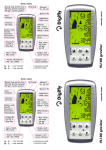


![TwoNav [platform][version]](http://vs1.manualzilla.com/store/data/006156188_1-a63caa055913f53929d6d89e582ab489-150x150.png)