1
RAN Systems, Inc.
______________________________________________________________________
1
ABOUT THE LINE LOGG-R ...................................................................................................................................... 1
2
GETTING STARTED ................................................................................................................................................... 3
2.1
2.1.1
2.1.2
2.1.3
2.1.4
2.1.5
2.1.6
2.1.7
2.1.8
2.2
2.3
2.4
2.5
3
INSTALLATION......................................................................................................................................................... 3
Plan The Installation and Configure the Hardware.......................................................................................... 3
Physical Installation, Grounding and Power .................................................................................................... 4
Connecting the Control Terminal or Modem. ................................................................................................... 4
Connecting the Local Printer ............................................................................................................................ 5
Data Storage Media........................................................................................................................................... 5
Operation and Data Base Configuration .......................................................................................................... 6
Connecting the Lines to be Monitored............................................................................................................... 7
Checking the Line Connections ......................................................................................................................... 8
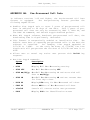
REMOTE RESET MODULE ........................................................................................................................................ 9
POSITION IDENTIFICATION FEATURE ....................................................................................................................... 9
START MONITORING.............................................................................................................................................. 10
USING THE TEST SET ............................................................................................................................................. 10
COMMAND SET/ERROR CODES........................................................................................................................... 11
3.1
ERROR MESSAGES ................................................................................................................................................. 11
3.1.1
Command Input Errors.................................................................................................................................... 11
3.1.2
General Disk Errors ........................................................................................................................................ 11
3.1.3
Specific Disk Errors (followed by messages)................................................................................................... 12
3.1.4
Other Errors .................................................................................................................................................... 12
4
OUTPUT REPORTS ................................................................................................................................................... 13
4.1
4.2
4.3
4.4
4.4.1
4.4.2
4.4.3
4.4.4
4.4.5
4.4.6
4.4.7
4.4.8
MANUAL AND AUTOMATIC REPORTING ................................................................................................................ 13
REPORT INTERVALS............................................................................................................................................... 13
TYPES OF REPORTS ................................................................................................................................................ 13
REPORT FORMAT ................................................................................................................................................... 15
Traffic Summary (01)....................................................................................................................................... 15
Average Call Duration (02)............................................................................................................................. 15
Chronological Detail (03) ............................................................................................................................... 16
Maintenance Detail (04).................................................................................................................................. 16
Multiple Line Detail (05) ................................................................................................................................. 17
Peg Count (06)................................................................................................................................................. 17
Busy Hour (07) ................................................................................................................................................ 18
Average Transmission Parameters (08) .......................................................................................................... 18
APPENDIX A: UNIT CONFIGURATION ....................................................................................................................... 19
A.1 ITEMS SHIPPED ............................................................................................................................................................. 19
A.2 CONFIGURATION WHEN SHIPPED.................................................................................................................................. 20
A.2.1 Common Equipment Chassis ................................................................................................................................ 20
A.2.2 Expansion Chassis................................................................................................................................................ 21
A.3 SITE CONFIGURATION CHART............................................................................................................................. 22
APPENDIX B: CONFIGURING THE COMMON EQUIPMENT CHASSIS................................................................ 27
B.1 POSITIONS OF THE CARDS IN THE COMMON EQUIP. CHASSIS ....................................................................................... 27
APPENDIX C: CONFIGURING THE EXPANSION CHASSIS ..................................................................................... 28
C.1 POSITIONS OF THE CARDS IN THE EXPANSION CHASSIS ............................................................................ 28
APPENDIX D: CONFIGURING THE TMS MODULE ................................................................................................... 29
______________________________________________________________________
Model LMT4911
USER'S MANUAL
V2.6 Page i
RAN Systems, Inc.
______________________________________________________________________
APPENDIX E: CONFIGURING THE LINE CARDS ...................................................................................................... 30
E.1 STANDARD LINE MONITORING, GROUND START AND VF TEST/MONITORING ACCESS CARDS .................................... 30
E.1.1 DIP Switch Settings .............................................................................................................................................. 30
E.1.2 Programming Strap Configuration ...................................................................................................................... 31
E.2 CALLER ID LINE MONITORING CARDS ......................................................................................................................... 31
E.2.1 Card Configuration .............................................................................................................................................. 31
E.2.2 Programming Strap Configuration ...................................................................................................................... 32
E.3 MASTER-SLAVE DIP SWITCH SW2 SETTINGS (ALL CARD TYPES)................................................................................. 34
APPENDIX F: CARD DIP SWITCH SETTINGS ............................................................................................................. 35
APPENDIX G: REMOTE RESET CONTROL ................................................................................................................. 37
G.1 RESET COMMAND SEQUENCE ............................................................................................................................. 37
G.2 CONNECTING THE TELEPHONE LINE................................................................................................................. 37
G.3 SETTING THE ADDRESS......................................................................................................................................... 38
APPENDIX H: MODEMS.................................................................................................................................................... 40
APPENDIX I: RETROFIT FOR EXPANSION CHASSIS INSTALLATION ............................................................... 42
I.1 ADDING AN EXPANSION CHASSIS ................................................................................................................................... 42
I.2 INSTALLATION PROCEDURE ................................................................................................................................. 42
APPENDIX J: TELEPHONE LINE 66 BLOCK DIAGRAM .......................................................................................... 44
J.1 CONNECTOR 66 BLOCK PINOUT ........................................................................................................................... 44
APPENDIX K: DIRECT PAIR CONNECTION DIAGRAM .......................................................................................... 45
K.1 DIRECT PAIR CONNECTION DIAGRAM .......................................................................................................................... 45
APPENDIX L: LINE LOGG-R NETWORK SECURITY SYSTEM .............................................................................. 46
L.1 INITIAL SECURITY SYSTEM CONFIGURATION ................................................................................................................ 46
L.2 LOGGING ON ................................................................................................................................................................. 47
L.3 LOGGING OFF ................................................................................................................................................................ 48
L.4 ACTIVATING NEW USERS .............................................................................................................................................. 48
L.5 CHANGING USER PASSWORDS ....................................................................................................................................... 48
L.5.1 Superuser .............................................................................................................................................................. 48
L.5.2 System Manager.................................................................................................................................................... 49
L.5.3 Regular User......................................................................................................................................................... 50
L.6 DEACTIVATING USERS .................................................................................................................................................. 50
L.7 USER COMMAND RESTRICTION ..................................................................................................................................... 50
L.7.1 Displaying The Allowed Command Set ................................................................................................................ 50
L.7.2 Changing The Allowed Command Set .................................................................................................................. 51
L.7.3 System Manager Command Set ............................................................................................................................ 51
L.7.4 User Command Set ............................................................................................................................................... 51
L.7.5 Automatic Log-off Feature.................................................................................................................................... 51
APPENDIX M: MASTER COMMAND SET..................................................................................................................... 52
M.1 COMMANDS ................................................................................................................................................................. 52
APPENDIX N: SPECIFICATIONS .................................................................................................................................... 65
N.1 GENERAL ...................................................................................................................................................................... 65
N.2 VF TESTING.................................................................................................................................................................. 67
N.3 POWER .......................................................................................................................................................................... 68
N.4 CONNECTORS ................................................................................................................................................................ 69
______________________________________________________________________
Model LMT4911
USER'S MANUAL
V2.6 Page ii
RAN Systems, Inc.
______________________________________________________________________
N.5 MECHANICAL ............................................................................................................................................................... 70
APPENDIX O: SYSTEM CLOCK SYNCHRONIZATION ............................................................................................ 71
APPENDIX P: SYSTEM CONFIGURATION FILE BACK-UP AND RESTORE CAPABILITY ............................. 74
APPENDIX Q: AUTOMATIC REPORT GENERATION ............................................................................................... 75
Q.1 DESCRIPTION AND FUNCTION ....................................................................................................................................... 75
Q.2 REPORTS GENERATED................................................................................................................................................... 76
Q.3 REPORT DESTINATION AND DURATION ......................................................................................................................... 76
Q.4 ACTIVATION/DEACTIVATION ........................................................................................................................................ 76
APPENDIX R: SYSTEM SITE NAME............................................................................................................................... 78
APPENDIX S: CLOCK CORRECTION FACTOR .......................................................................................................... 79
APPENDIX T: SYSTEM SERIAL NUMBER ................................................................................................................... 80
APPENDIX U: SYSTEM I/O TEST.................................................................................................................................... 81
APPENDIX V: SET SYSTEM CONFIGURATION TO DEFAULT VALUES.............................................................. 82
APPENDIX W: TONE POSITION IDENTIFIER............................................................................................................. 83
W.1 OVERVIEW ............................................................................................................................................................... 83
W.2 SYSTEM CONFIGURATION ................................................................................................................................... 83
W.2.1 Position ID Tone Transmitter LMT 4911-17....................................................................................................... 84
W.2.2 Position ID Receivers .......................................................................................................................................... 84
W.3 SPECIFICATIONS..................................................................................................................................................... 85
W.3.1 General ................................................................................................................................................................ 85
W.3.2 Transmitter .......................................................................................................................................................... 85
W.3.3 Receiver ............................................................................................................................................................... 86
W.4 POSITION ID TRANSMITTER CODES .................................................................................................................. 87
W.5 TRANSMITTER DIP SWITCH AND STRAP LOCATIONS .................................................................................................... 88
W.6 TRANSMITTER STRAPPING.................................................................................................................................. 89
W.6.1 Repeat Transmit Mode......................................................................................................................................... 89
W.6.2 Transmit Level ..................................................................................................................................................... 89
W.6.3 Intercall Timeout ................................................................................................................................................. 90
APPENDIX X: CONTACT POSITION IDENTIFIER .................................................................................................... 91
X.1 DESCRIPTION ........................................................................................................................................................... 91
X.2 INSTALLATION ........................................................................................................................................................ 91
X.2.1 System Installation................................................................................................................................................ 91
X.2.2 Connection of Existing Position Status Contacts ................................................................................................. 92
X.3 CONTACT DRIVEN POSITION SENDER RELAY (LMT 4911-27) ..................................................................... 94
X.4 HANDSET DRIVEN POSITION SENDER RELAY (LMT 4911-24) ...................................................................... 97
APPENDIX Z: OUT-OF-SERVICE DETECTION ........................................................................................................... 99
Z.1 GENERAL ................................................................................................................................................................... 99
Z.2 OUT-OF-SERVICE DETECTION ADMINISTRATION ........................................................................................ 100
Z.3 DOMX OUTPUT REPORT MATRIX ...................................................................................................................... 102
APPENDIX AA: EXCEPTION REPORTING ............................................................................................................... 103
AA.1 OVERVIEW............................................................................................................................................................... 103
______________________________________________________________________
Model LMT4911
USER'S MANUAL
V2.6 Page iii
RAN Systems, Inc.
______________________________________________________________________
AA.2 AUTOMATIC OUTPUT REPORTS....................................................................................................................... 103
AA.3 USER REQUESTED OUTPUT REPORTS............................................................................................................ 104
AA.4 EXCEPTION LOG DATABASE ............................................................................................................................. 104
APPENDIX AB: PRE-PROCESSED CALL DATA ....................................................................................................... 105
APPENDIX AC: ENHANCED ANI .................................................................................................................................. 107
______________________________________________________________________
Model LMT4911
USER'S MANUAL
V2.6 Page iv
RAN Systems, Inc.
______________________________________________________________________
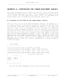
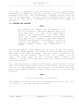
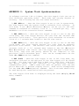
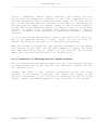
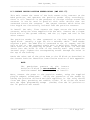
GENERAL
This manual covers all Line Logg-Rs equipped with software Version
1.41 or higher.
In order to provide our customers with the best possible performance
features, RAN Systems is constantly enhancing the software used in the
Model LMT-4911. Thus, it is impractical to list all the capabilities
of your version of software in this manual.
To obtain the capabilities of the particular version of software with
which your unit is equipped, enter:
DVER
Technical Specifications
APPENDIX N.
for
the
Line
Logg-R
are
delineated
in
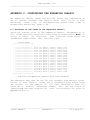
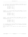
LOGGING ON
Model 4911 is equipped with security, in the form of passwords that
are required for logging on to either port.
To discourage hackers,
Model 4911 does not ask for the password, so the user must know the
correct command (verb and modifier) to log on. After the unit has been
turned on, and time has been allowed for it to boot, a power-up
message will be displayed, followed by a prompt =>. If the message
and/or the prompt is not displayed or is garbled, the terminal
connected to the port is probably set incorrectly. Make certain that
the settings are 1200 baud, 8 data bits, no parity, 1 stop bit, full
duplex, and then reboot the Line Logg-R. Once the correct prompt is
displayed, first time users can log on by entering:
SLOG 1
The Line Logg-R will reply: PASSWORD? Enter SUPERUSER and hit return.
A welcome message should then be received and the unit is now fully
operational. We strongly recommend that APPENDIX L be fully read
before proceeding.
1 ABOUT THE LINE LOGG-R
The Line Logg-R monitors and tests from 1 to 80 two-wire lines,
recording all the events that occur on the lines and time stamping
them to the nearest 10 milliseconds. Complete reports are then
available, categorized by event, statistic or summary.
The Line Logg-R stores up to two month’s of monitored call data and
2 years of pre-processed call data which can be electronically
archived, if so desired.
______________________________________________________________________
Model LMT4911
USER'S MANUAL
V2.6 Page 1
RAN Systems, Inc.
______________________________________________________________________
In addition to the monitored data, the Line Logg-R stores a name or
number of up to 16 characters in length for each line. Any number of
lines may be grouped together for reporting purposes in one or more
groups, and each group may also be named. A line may be a member of
more than one group, and there can be from one to sixteen groups.
The Line Logg-R is controlled via either of two RS-232 ports. Both
ports are suitable for use with a local terminal or a modem. Security
is provided for both ports by means of passwords.
Depending upon the size of the installation, the Line Logg-R consists
of either one or two units, both of which are the same physical size.
The Common Equipment Chassis holds from 1 to 5 monitor cards, for a
maximum capacity of 40 lines. An Expansion Chassis which holds an
additional 16 cards may be connected to the Line Logg-R to provide a
maximum 80 line capacity in a single system.
The Line Logg-R records the following events, which it uses to create
reports:
Incoming Ring:
Ring Voltage start/termination
TIP-RING Supervision Status:
Seized/idle states, normal and reversed battery
Normal/reversed battery
Open/grounded states, TIP and RING
MF Digits (option -04):
Valid Digit received/terminated
DTMF Digits (Standard):
Valid Digit received/terminated
CND (Caller Number Delivery/Caller ID) Digits (option -25)
Valid Digit received/terminated
Wink, Flash and Transient Events
The Line Logg-R maintains an audit trail for stored and incoming data
by time stamping all data files at 10 minute intervals, and by
recording both the time and the status of all lines each time it is
powered-up or booted.
______________________________________________________________________
Model LMT4911
USER'S MANUAL
V2.6 Page 2
RAN Systems, Inc.
______________________________________________________________________
Additionally, the Line Logg-R can be equipped with a TMS card
(option -03) which contains two VF test sets, designated A and B.
Test Set A is a full TMS, and is also equipped with a DC Voltmeter
which reports T-Gnd, R-Gnd and T-R voltages. This set is used for
manual testing of individual lines, which can be accomplished without
interrupting the monitoring of any of the lines.
Four wire private line circuits, such as dedicated modem links, may be
monitored and tested with the TMS Module by installing a VF
Test/Monitor Card (option -08) instead of a Line Monitoring Card.
Test Set B is a monitor only level/noise meter used for continuous
monitoring of live traffic for transmission parameter analysis.
2 GETTING STARTED
Before installing the Line Logg-R, unpack all components and check for
damage.
Next, check the system’s serial number and configuration
against the information in APPENDIX A of this manual. Be certain it
agrees with your order.
2.1 Installation
The correct installation sequence for the Line Logg-R is:
•
•
•
•
•
•
•
•
•
Plan the installation and configure the unit.
Physical installation, power, local ground.
Connect modems and/or terminals.
Connect local printer (if used).
Operate the Unit.
Configure the Unit Data Base.
Connect the lines to be monitored.
Test all lines for correct connection.
Start monitoring with STRT command.
2.1.1 Plan The Installation and Configure the Hardware
Make a plan: decide which lines will be connected to what inputs of
the system and record on the charts provided in APPENDIX A. Keep the
charts current when changes are made.
Configure the hardware: Check the settings (DIP switches, jumpers,
slot locations, etc.) of all cards against the intended usage.
Appendices B, C, D, E, F, G, J, K, R, S, T, X and W all address
hardware configuration/optioning of various Line Logg-R elements.
Refer to the "Installation and Maintenance Manual" for more details.
______________________________________________________________________
Model LMT4911
USER'S MANUAL
V2.6 Page 3
RAN Systems, Inc.
______________________________________________________________________
2.1.2 Physical Installation, Grounding and Power
Line Logg-R requires no special installation. You may have one or two
units, depending on system size. Mount them in a bay or rack, using
the adjustable mounting ears (supplied), or place them on a flat
surface. Each unit comes equipped with rubber feet.
If you are
mounting them in a rack, remove the feet. If you have two units
(Common Equipment Chassis and Expansion Chassis), mount the Common
Equipment Chassis below the Expansion Chassis.
The two must not be
separated in the rack by more that 1/2”. If you are placing them on a
shelf or table place the Expansion Chassis on top of the Common
Equipment Chassis.
If two units
cables:
are
involved,
interconnect
them
with
the
following
Power Cable
9402B09
Signal Cable 9402B04
Control Cable 9402B03
The Power Cable has identical connectors on both ends, and can be
inserted only into the matching receptacles on the rear panels of the
two units. The same is true for the Signal Cable. The Control Cable is
shipped with one end connected inside the Common Equipment Chassis.
Connect the other end to the corresponding connector on the rear of
the Expansion Chassis.
Ground the common unit to the local power ground or telephone ground
with a #18 or larger stranded ground wire. Do not rely on the third
pin ground provided by the power cord. If you have an Expansion
Chassis, ground it to the Common Chassis. Make certain that the power
switch (on the rear panel) is in the OFF position, then plug the
supplied power cord into any standard 110VAC 60HZ power receptacle.
UPS power is desirable, but not mandatory, as the Line Logg-R
automatically transfers its data to disk once a minute to protect
against loss.
2.1.3 Connecting the Control Terminal or Modem.
Line Logg-R is equipped with two control ports, designated COM1 and
COM2. The two ports are identical in function and may be used with a
terminal or modem. Both ports are DTE, and Line Logg-Rs are shipped
with both ports set to 1200 baud, 8 data bits, no parity, 1 stop bit,
full duplex.
If you require a different setting use the SCOM command
to change the settings. After you have changed the settings, reboot
by powering down and the system will change to the new values. Port
settings are stored on the system disk, and are automatically set to
the selected values on power up.
______________________________________________________________________
Model LMT4911
USER'S MANUAL
V2.6 Page 4
RAN Systems, Inc.
______________________________________________________________________
2.1.3.1 Modem
Modems may be used with either or both ports. Connect the modem with
a straight through RS-232 cable equipped with a DB-25 male connector
at the Line Logg-R end. Select modems that are compatible with the
baud rate. See APPENDIX H.
2.1.3.2 Terminal
Terminals may be used with either or both ports. Connect the terminal
via a null modem cable. Set the terminal to match the selected port
characteristics.
2.1.4 Connecting the Local Printer
If a local printer is to be used for reports, connect any standard
parallel printer to the printer port on the rear of the Line Logg-R.
Use a standard IBM printer cable. The Line Logg-R outputs all data to
the printer as a series of ASCII characters, so any printer that can
reproduce parallel ASCII is satisfactory.
2.1.5 Data Storage Media
The Line Logg-R is equipped with one 3½ inch high density 1.44
megabyte disk drive on the front panel and a minimum of a 120 MB hard
disk. All data, the operating system, programs, overlays and
configuration files are stored on the hard disk. The hard disk also
stores the user configurable data base, such as line types, off hook
threshold voltages, enabled and disabled lines, line names, group
names, line numbers, etc.
The data gathered by call monitoring is recorded on the internal hard
disk. The drive on the front panel is used to create archive disks
and load software version upgrades. Stored data from the hard drive
can be transferred, on command, to a floppy disk in the front drive,
which can then be removed for archiving. The unit is typically
operated without a disk in the front drive. A Line Logg-R should only
be powered-up with a disk in the floppy disk drive during software
version upgrade procedures. Refer to APPENDIX P for details on System
configuration back-up/restoration procedures.
The front drive requires a DSHD (double sided, high density) disk IBM
formatted at 1.44MB.
______________________________________________________________________
Model LMT4911
USER'S MANUAL
V2.6 Page 5
RAN Systems, Inc.
______________________________________________________________________
2.1.6 Operation and Data Base Configuration
2.1.6.1 Operation
A Line Logg-R, equipped with software Version 1.41 or higher
accommodates up to two users, logged on simultaneously, on different
COM ports. It processes user command requests on a first in, first
out basis.
A Line Logg-R is configured and activated via the terminal(s). On
power up (power switch on rear panel), the Line Logg-R's computer will
boot and then display its name and version on the terminal(s). This
will be followed by a System prompt: =>
Once the prompt appears, the unit will accept a user log on. The
following are requirements to access the Line Logg-R system:
1. A user must have an assigned user number and password, and must
log on via the SLOG command. For more information on passwords
and log on, see APPENDIX L.
2. Any user can log on to any COM port, provided the port is idle.
A COM port is idle when no user is logged on to that port.
3. On occasion, a user will receive the message “SYSTEM BUSY”. This
indicates that the system is processing the other COM port’s
request and will process your request momentarily. This typically
occurs during the creation of large detailed call reports via the
CRPT command.
Initially, only the Superuser (SU) and the System Manager (SM) user
numbers are active. The SU password is ‘SUPERUSER’ and the SM password
is ‘SYSTEM MANAGER’. Do not type the quotation marks in the password.
Log on to either COM Port as SU, and the unit will accept commands.
Each command must be followed by <ENTER>.
Commands consist of four
letters, followed by one or more fields (the fields vary with the
commands).
Commands can be separated into two groups, set commands
which begin with an ‘S’, and display commands which begin with a ‘D’.
Each set command as a corresponding display command.
Additionally,
there are several create commands, which begin with a ‘C’, for
creating output.
These are used to create reports from the data
stored on the hard disk. They are also used to create archive disks.
The command set is specifically defined in APPENDIX M.
______________________________________________________________________
Model LMT4911
USER'S MANUAL
V2.6 Page 6
RAN Systems, Inc.
______________________________________________________________________
2.1.6.2 Data Base Configuration
In order to correctly monitor, the Line Logg-R must know, for each
line, the busy (off hook) threshold voltage and type of supervision.
Additionally, the date and time must be correct, and the lines to be
monitored must be enabled. Line Logg-Rs are shipped with all lines
disabled, thresholds set to -45 volts, line types set to Loop Start,
the time to Eastern Standard Time, and all groups, group names and
line names blank. Additionally, COM ports 1&2 are set to 1200 baud, 8
data bits, no parity, full duplex. These settings can be changed as
required.
All settings are saved on the hard disk, and are automatically
restored to the previously set values on power-up. The clock in the
Line Logg-R has battery back-up, and thus runs continuously. Once the
unit has been programmed, it is not necessary to reset any values on
power-up.
At this time, enter the correct date and time as well as all the line
and group names, so that when scanning first begins all the data will
be useful. Do not enable any lines at this time, as the lines have to
be connected, checked for correct TIP-RING polarity, and threshold.
Postpone the checking of threshold values for the lines (and changing
them if necessary) until the lines have been connected, then proceed
in accordance with Section 2.1.8.2. of this document.
2.1.7 Connecting the Lines to be Monitored
Connection is made by bridging the Line Logg-R across the pairs at any
convenient point in the facility. Usually, this will be a connector
block such as a Type 66 block or a distribution frame.
______________________________________________________________________
Model LMT4911
USER'S MANUAL
V2.6 Page 7
RAN Systems, Inc.
______________________________________________________________________
2.1.7.1 Via 66 Type Connector Blocks
Sets of 25 pair ‘Type 66’ connector blocks with mating VF cables are
shipped with each Line Logg-R.
One block and cable set is shipped
with the Common Equipment Chassis, and up to three sets are shipped
with the Expansion Chassis. Each block and cable set connects 20 lines
to the Line Logg-R.
Mount the block on any convenient surface and
connect it to one VF connector on the rear of the Line Logg-R. Bridge
the first 20 pairs on the block across the lines to be monitored by
connecting pairs from the block to any convenient block in your
distribution system. Additionally, connect the last two terminals to
the local telephone ground. The remaining three blocks (if supplied)
are connected to the connectors on the expansion chassis, and bridged
across lines 21-40, 41-60 and 61-80 per APPENDIX J. If Caller ID Line
Cards are used, which have 8 rather than 4 line circuits per card,
lines 1-40 may be connected to the Common Equipment Chassis with lines
41-80 connected to the Expansion Chassis.
2.1.7.2 Direct Connection
The Line Logg-R may also be connected directly across the lines to be
monitored, although this method of connection is not recommended.
Obtain a suitable cable equipped with a standard 25 pair male ribbon
connector at the Line Logg-R end, and connect the lines per
APPENDIX K.
2.1.8 Checking the Line Connections
2.1.8.1 Checking for TIP-RING Reversals
Once the lines are connected, check them for correct TIP-RING
polarity. The DC voltmeter in the Line Logg-R's TMS card should be
used, if your unit is so equipped. If it is not equipped with a TMS
Card, use any good quality voltmeter connected across the TIP and RING
outputs of the type 310 TEST ACCESS connector located on the rear
panel of the Common Unit. We recommend this connection so that TIPRING reversals can be seen on the voltmeter. Proceed as follows:
First, connect the TMS or voltmeter to the line to be checked by using
the STST command. Next, read the TIP and RING voltages with the TMS
by using the SMES DCV R command, or directly with the voltmeter. Wait
for the line to go idle (on hook).
When this happens, the TIP to
Ground voltage should be very close to zero (typically 0 to -3 volts),
and the RING to Ground voltage should be close to -48 volts. If they
are reversed, correct your connection before starting the scan.
______________________________________________________________________
Model LMT4911
USER'S MANUAL
V2.6 Page 8
RAN Systems, Inc.
______________________________________________________________________
2.1.8.2 Setting the Hold Voltage Thresholds
Check and set the thresholds as follows for each line, except for
lines terminating on Caller ID Line Cards. Caller ID Card terminated
lines all have preset thresholds and therefore no such threshold level
determination is needed.
First, note the RING lead idle (on hook) voltage. Next, when the line
comes busy, note the busy (off hook) voltage of whichever lead is the
most negative. For ground start and loop start lines this will be the
RING
lead. For other types of lines, such as DID and reverse
signaling, this may be the TIP lead. These values are needed as a
guide for setting the hold voltage threshold for the line.
Finally, using the SHLV command, set the hold voltage threshold for
the line to a value midway between the idle voltage level and the busy
voltage level, as previously observed with the DC voltmeter. For
example, if the idle voltage is 49 volts and the busy voltage is 35
volts, the difference is (49-35) = 14 volts. Half this difference is 7
volts. The correct threshold setting is therefore (49-7) = 42 volts.
Repeat this procedure for each line until every line has been verified
as correctly connected. Once the unit is running, the validity of the
threshold settings for each line can be verified by making test calls
and checking a multi-line detail report for the test call time period.
2.2 Remote Reset Module
This optional module (option -19) permits the Line Logg-R to be
remotely
“rebooted”
via
a
call
placed
to
a
pre-designated
administrative line connected to the Line Logg-R. This module does not
plug into the units’ mother board, but rather is jumpered to cross
connect punch connectors on the motherboard and to the selected admin
line on the telephone line input connector block. Refer to APPENDIX G
for configuration and connection details. Record the telephone number
assigned to this remote reset module on APPENDIX A.
2.3 Position Identification Feature
There are two methods of position identification used by the Line
Logg-R system, Tone (option -17) and Contact (option -27) driven.
Only one method can be implemented in an individual Line Logg-R
system.
Tone position identifiers are described in APPENDIX W and
Contact position identifiers are explained in APPENDIX X of this
manual.
______________________________________________________________________
Model LMT4911
USER'S MANUAL
V2.6 Page 9
RAN Systems, Inc.
______________________________________________________________________
2.4 Start Monitoring
To place the Line Logg-R into operation, enable all lines to be
scanned with the SENL command. The Line Logg-R will immediately start
scanning all enabled lines. If the power is on and the scanning was
previously stopped with the STOP command, start the scan with the STRT
command.
2.5 Using the Test Set
The test Set can be used while monitoring proceeds. It can be bridged
across a line that is enabled for scanning, but if so, the send tone
function should not be used (to avoid inadvertent disruption of
traffic).
To use the set, select a line for test with the STST
command and then issue the appropriate tone or measure command. When
finished, select line 0 with the STST command to disconnect the test
set.
______________________________________________________________________
Model LMT4911
USER'S MANUAL
V2.6 Page 10
RAN Systems, Inc.
______________________________________________________________________
3
COMMAND SET/ERROR CODES
The command set consists of three basic types of commands: (S)et,
(D)isplay, and (C)reate. Each type begins with the letters C, D or S
and ends with a carriage return [CR]. APPENDIX M alphabetically lists
all valid commands with their respective arguments and required
action.
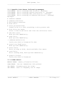
3.1 Error Messages
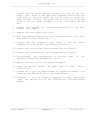
3.1.1 Command Input Errors
COMMAND ERROR: Syntax.
COMMAND ERROR: Not implemented.
COMMAND ERROR: Invalid command.
COMMAND ERROR: Invalid parameter.
COMMAND ERROR: Parameter not supported.
COMMAND ERROR: No files for date requested.
COMMAND ERROR: Invalid operation requested.
COMMAND ERROR: Maximum character input limit exceeded.
COMMAND ERROR: Unknown line type, report not implemented.
3.1.2 General Disk Errors
DISK ERROR: No Disk.
DISK ERROR: Can not access disk.
DISK ERROR: Can not read file sizes.
DISK ERROR: DOS copy command failed.
DISK ERROR: Can not open file <......>.
DISK ERROR: Can not access system disk.
DISK ERROR: Write fail to file <......>.
DISK ERROR: Can not open file VERSION.TXT.
DISK ERROR: Can not save the POWERUP file.
DISK ERROR: System disk required in drive A.
DISK ERROR: Can not open data disk directory.
DISK ERROR: Data Path not set to hard disk drive C.
DISK ERROR: Can not run DOS commands from system disk.
______________________________________________________________________
Model LMT4911
USER'S MANUAL
V2.6 Page 11
RAN Systems, Inc.
______________________________________________________________________
3.1.3 Specific Disk Errors (followed by messages)
DISK ERROR: Error accessing disk drive A-- [message]
DISK ERROR: Error accessing System disk drive C-- [message]
DISK ERROR: Error accessing Data disk drive D-- [message]
DISK ERROR: Error accessing an unknown disk drive-- [message]
Messages:
•
•
•
•
•
unknown command.
unknown disk drive.
bad request structure.
disk error.
write protected disk.
Cannot write to a disk containing a write protect tab.
•
disk drive not ready.
Place a disk in the drive and close the disk drive latch.
•
CRC data error.
Back up disk immediately.
•
seek error.
Back up disk immediately.
---unknown medium error
Verify the disk is formatted for DOS.
•
sector not found error.
Back up disk immediately.
•
write fault.
Error writing to disk, check available free space.
•
read fault.
Error reading disk, Back up disk immediately.
•
general failure.
Verify the disk is formatted.
3.1.4 Other Errors
MEMORY ERROR: Memory allocation failure.
COMM ERROR:
Can not communicate with printer.
TMS ERROR:
Frequency port not ready.
TMS ERROR:
Level or frequency out of range.
______________________________________________________________________
Model LMT4911
USER'S MANUAL
V2.6 Page 12
RAN Systems, Inc.
______________________________________________________________________
4
OUTPUT REPORTS
4.1 Manual and Automatic Reporting
Reports may be generated manually at any time by invoking the Create
Report (CRPT) command.
They may also be generated automatically by
invoking the Set Automatic Report Generation (SARG) command per
APPENDIX Q. Manual reports may be generated regardless of whether
Automatic Reporting is enabled or disabled.
4.2 Report Intervals
Reports can be requested for any interval from 1 to 24 hours, in
increments of 1 hour. Any time interval, past, present or future, can
be requested.
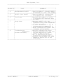
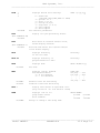
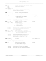
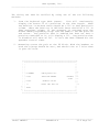
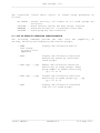
4.3 Types of Reports
Reports can be created for all lines, or for a specific group of
lines.
Up to 16 groups can be defined, each containing up to 80
lines. A line may be included in more than one group. The following
types of reports are available:
+--------+----------------------+--------------------------------+
|REPORT #|
TYPE
|
COMMENTS
|
|========|======================|================================|
| 1
| Traffic Summary
| Reports the total traffic on
|
|
|
| each circuit. This can be
|
|
|
| DATA, VOICE, GROUP(s) or ALL. |
|
|
| For DATA and VOICE, requires
|
|
|
| VOICE GROUP and DATA GROUP
|
|
|
| be specified in the data base.|
|
|
| Traffic density is reported in |
|
|
| Hundred Call Seconds (CCS).
|
|
|
| One CCS is 100 seconds of call |
|
|
| activity (36 CCS = 1 hour).
|
+--------+----------------------+--------------------------------+
| 2
| Average Call Duration| Reports average call duration |
|
|
| for each circuit in the GROUP |
|
|
| or GROUPs specified, or ALL
|
|
|
| circuits.
|
+--------+----------------------+--------------------------------+
| 3
| Chronological Detail | Reports number of rings, call |
|
|
| length, DTMF and/or MF digits |
|
|
| for each call. Also, reports |
|
|
| originate incoming/outgoing
|
|
|
| for Loop Start & DID lines,
|
|
|
| disconnect incoming/outgoing
|
|
|
| for DID lines.
|
+--------+----------------------+--------------------------------+
______________________________________________________________________
Model LMT4911
USER'S MANUAL
V2.6 Page 13
RAN Systems, Inc.
______________________________________________________________________
+--------+----------------------+--------------------------------+
|REPORT #|
TYPE
|
COMMENTS
|
|========|======================|================================|
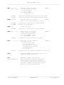
| 4
| Maintenance Detail
| Same as Report 3 except report |
|
|
| presented on a per line format|
+--------+----------------------+--------------------------------+
| 5
| Multi Line Detail
| Same as Report 4 except does
|
|
|
| not report call failures.
|
+--------+----------------------+--------------------------------+
| 6
| Peg Count
| Reports the number of calls
|
|
|
| originated and answered hour |
|
|
| by hour.
|
+--------+----------------------+--------------------------------+
| 7
| Busy Hour
| Reports traffic for the
|
|
|
| busiest hour in the requested |
|
|
| interval. Busy hour begins at |
|
|
| 15 min intervals.
|
|
|
| An hour is defined as any 60
|
|
|
| minute period commencing on
|
|
|
| any 15 minute boundary.
|
|
|
| Three listings are given: ALL, |
|
|
| INCOMING and OUTGOING.
|
+--------+----------------------+--------------------------------+
| 8
| Transmission
| Reports transmission para|
|
|
Parameters | meters averaged over the last |
|
|(Future Release)
| 48 hour period for VOICE,
|
|
|
| DATA, or ALL circuits.
|
|
|
| Out of specification para|
|
|
| meters are flagged with ‘*’. |
|
|
| Requires VOICE GROUP and DATA |
|
|
| GROUP be specified in the
|
|
|
| data base.
|
+--------+----------------------+--------------------------------+
______________________________________________________________________
Model LMT4911
USER'S MANUAL
V2.6 Page 14
RAN Systems, Inc.
______________________________________________________________________
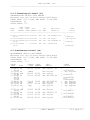
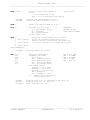
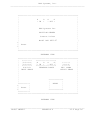
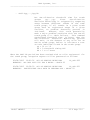
4.4 Report Format
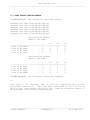
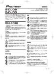
4.4.1 Traffic Summary (01)
SITE NAME
TRAFFIC SUMMARY: CCS for 24 hours ending 0700, March 28, 1994
GROUP(S): Ohio 694, Ohio 293
CCS From 1900 Hours to 0600 Hours
----------------------------------LINE
6
5
4
3
2
1
0
23 22 21 20 19
---------------- --- --- --- --- --- --- --- --- --- --- --- --2 694-2234
4
7
4
2
1
1
0
0
1
1
1
0
9 694-8822
6
0
0
0
1
2
0
1
0
2
0
1
13 694-8823
5
5
3
1
0
0
1
1
0
o
2
0
14 694-8834
0
0
0
0
0
0
0
0
0
0
0
0
20 694-8835
4
6
1
1
1
1
1
0
0
0
2
1
3 293-1141
3
5
2
0
0
1
2
0
1
1
0
0
4 293-1142
4
2
0
1
1
0
1
0
0
0
1
1
18 293-1143
2
5
1
0
1
1
0
0
0
0
0
2
19 293-1145
2
3
0
0
0
1
0
0
1
1
0
2
CCS From 0700 Hours to 1800 Hours
----------------------------------LINE
18 17 16 15 14 13 12 11 10 9
8
7
---------------- --- --- --- --- --- --- --- --- --- --- --- --2 694-2234
4
7
4
2
6
1
1
2
0
1
0
0
9 694-8822
6
0
3
1
4
2
0
3
1
0
0
1
13 694-8823
5
5
4
1
5
3
1
0
0
1
0
0
14 694-8834
0
0
0
0
0
0
3
1
1
0
1
0
20 694-8835
4
6
6
3
4
1
1
2
0
1
0
0
3 293-1141
3
5
2
2
3
1
4
1
1
0
1
0
4 293-1142
4
2
2
4
4
2
1
1
0
3
0
0
18 293-1143
2
5
3
1
3
1
2
2
0
1
1
1
19 293-1145
2
3
5
0
6
4
1
0
4
2
0
0
REPORT STATUS: REPORT SUCESSFULLY COMPLETED
4.4.2 Average Call Duration (02)
SITE NAME
AVERAGE CALL DURATION IN MINUTES
Averaged over the 24 hours ending 0700 March 28, 1994
GROUP(S): Ohio 694, Ohio 293
INCOMING
OUTGOING
AVERAGE TOTAL
AVERAGE TOTAL
LINE
MINUTES CALLS
MINUTES CALLS
---------------- -------------------------------2 694-2234
2.6
71
4.3
85
9 694-8822
1.5
12
1.0
16
13 694-8823
3.3
111
2.5
126
14 694-8834
0.0
0
0.0
0
20 694-8835
2.0
22
3.6
64
3 293-1141
9.7
2
0.0
0
4 293-1142
4.2
81
2.4
97
18 293-1143
2.1
127
5.9
110
19 293-1145
2.7
66
3.3
126
REPORT STATUS: REPORT SUCCESSFULLY COMPLETED
______________________________________________________________________
Model LMT4911
USER'S MANUAL
V2.6 Page 15
RAN Systems, Inc.
______________________________________________________________________
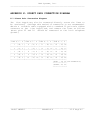
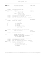
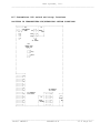
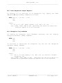
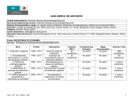
4.4.3 Chronological Detail (03)
CHRONOLOGICAL DETAIL CALL REPORT
Measured over the 24 hours ending 0000 Hours
START DATE: 12-27-1994, END DATE: 12-28-1994
LINE/GROUP: G1
TOTAL CALLS: 173
LINE C'NECT
START
TYPE
TIME
CALL
POS
ANI DIGITS
DTMF
TIME
NUMBER RINGS LENGTH DISC NUM
CALLER ID
DIGITS
------------------------------------------------------------------------13:04:11
04:31
13:12:03
13:20:41
21:20
13:21:40
22:15
DID002 00:10 00:01:22
STN
001
<KP 24933170 ST
DID001 01:10 00:12:05
DID004 00:15 00:03:22
CO
STN
002
003
<No Digits
<KP 24930000 ST
CID008
STN
006
<5614221100
3
00:02:02
>
F<6781123>
> <No Digits>
>
F<443135>
>
F<4432278>
4.4.4 Maintenance Detail (04)
MAINTENANCE DETAIL CALL REPORT
Measured over the 24 hours ending 0000 Hours
START DATE: 12-27-1994, END DATE: 12-28-1994
LINE/GROUP: G1
TOTAL CALLS: 173
START
TIME
DISC
13:04:11
05:15
13:12:03
13:20:41
21:45
13:21:40
22:55
23:10
23:45
13:49:31
14:10:02
14:33:42
15:39:13
|
|
23:37:11
39:21
00:22:02
23:59
00:41:29
43:12
03:35:00
C’NECT CALL
TIME LENGTH
CO
CO
STN
CO
00:30
ABNA
00:45
01:04
01:22
CO
CO
CO
CO
|
|
STN
CO
CO
CO
01:35
ABNA
01:1
PAD
|
|
01:03
01:04
01:22
00:24
10:29
03:14
|
|
09:22
11:59
07:33
03:31
03:22
02:02
ANI
DIGITS
<KP
<No
<No
<KP
2493317 ST
Digits
Digits
4221100 ST
<KP
<No
<No
<No
4221100 ST
Digits
Digits
Digits
|
|
Digits
2493317 ST
Digits
Digits
<No
<KP
<No
<No
DTMF
DIGITS
>
F<6781123>
> <No Digits>
>
F<443135>
>
F<4432278>
F<>
F<4432289>
> <No Digits>
> <No Digits>
> <No Digits>
> <No Digits>
|
|
>
F<2249877>
>
F<6783419>
>
F<6783477>
> F<6781123>
______________________________________________________________________
Model LMT4911
USER'S MANUAL
V2.6 Page 16
RAN Systems, Inc.
______________________________________________________________________
4.4.5 Multiple Line Detail (05)
Multi Line Detail reports are essentially a series of Maintenance
Detail reports printed sequentially.
Due to their length, they are
not illustrated here. Refer to Maintenance Detail reports for format.
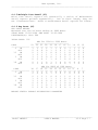
4.4.6 Peg Count (06)
PEG COUNT REPORT
Measured over the 24 hours ending at 0000 Hours
START DATE: 12-02-1994 END DATE: 12-03-1994
LINE/GROUP(S): Ohio 694
TOTAL CALLS: 116
LINE
23
---------------- --2
IN
1
OUT
2
13
IN
2
OUT
1
3
IN
3
OUT
2
18
IN
2
OUT
2
LINE
18
---------------- --2
IN
3
OUT
2
13
IN
2
OUT
1
3
IN
3
OUT
2
18
IN
2
OUT
2
PEG for 1200 to 2300 Hours
----------------------------22 21 20 19 18 17 16 15 14
--- --- --- --- --- --- --- --- --3
1
2
1
1
0
0
1
1
0
0
0
1
2
0
1
0
2
1
3
1
0
0
1
1
0
1
2
1
1
1
1
1
0
0
0
1
2
0
0
1
2
0
1
1
2
0
1
1
0
1
0
0
0
1
1
0
1
1
0
0
0
0
3
0
0
0
1
0
0
1
1
PEG for 0000 t0 1100 Hours
----------------------------17 16 15 14 13 12 11 10 9
--- --- --- --- --- --- --- --- --2
1
5
2
0
0
0
0
0
0
0
0
1
2
0
1
0
2
1
3
1
0
0
1
1
0
1
2
1
1
1
1
1
0
0
0
1
2
0
0
1
2
0
1
1
2
0
1
1
0
1
0
0
0
1
1
0
1
1
0
0
0
0
3
0
0
0
1
0
0
1
1
13 12
--- --1
0
0
1
2
0
2
1
0
0
1
1
0
2
0
2
8
7
--- --0
0
0
1
2
0
2
1
0
0
1
1
0
2
0
2
REPORT STATUS: REPORT SUCCESSFULLY COMPLETED
______________________________________________________________________
Model LMT4911
USER'S MANUAL
V2.6 Page 17
RAN Systems, Inc.
______________________________________________________________________
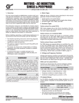
4.4.7 Busy Hour (07)
BUSY HOUR TRAFFIC REPORT
Measured over the 24 hours ending 0000 Hours
START DATE: 12-04-1994 END DATE: 12-05-1994
LINE/GROUP(S): Ohio 694
TOTAL CALLS: 94
CIRCUIT DATA
COMBINED
INCOMING
-----------------------------Hour Beginning
12-04-1997@0900 12-04-1997@0900
Max. # Ckts. Busy
16
8
All Busy Seconds
21
11
Total CCS
193
106
Average CCS
18
14
Total Calls
94
55
Average Call Seconds
129
103
Calls Ring No Answer
4
1
OUTGOING
-------12-04-1997@0900
8
10
87
21
39
155
3
REPORT STATUS: REPORT SUCCESSFULLY COMPLETED
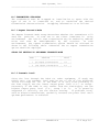
4.4.8 Average Transmission Parameters (08)
AVERAGE TRANSMISSION PARAMETERS:
Averaged over the last 48 hour period ending 07 AM, March 28, 1992
GROUP(S): Ohio 694,
TRUNK
---------------2 694-2234
9 694-8822
13 694-8823
14 694-8834
20 694-8835
3 293-1141
4 293-1142
18 293-1143
19 293-1145
Ohio 293
LEVEL (dBm)
-----------22
-27
-20
-40 *
-18 *
-21
-37 *
-20
-22
C-MSG NOISE (dBrnCO)
------------------25
21
24
20 *
29
30 *
20 *
23
20 *
______________________________________________________________________
Model LMT4911
USER'S MANUAL
V2.6 Page 18
RAN Systems, Inc.
______________________________________________________________________
APPENDIX A:
UNIT CONFIGURATION
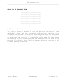
A.1 Items Shipped
This manual shipped with Model LMT-4911-00, Serial # _______
Items Shipped
+----------------------------------------------+-----+
|
ITEM & CODE NUMBER
| QTY |
|==============================================+=====|
| Basic Unit- One hard disk+floppy disk (-00) |
|
|----------------------------------------------+-----+
| TMS Module (-03)
|
|
+----------------------------------------------+-----+
| Standard Line Monitor Cards (-01)
|
|
+----------------------------------------------+-----+
| Caller ID Line Monitor Cards (-06)
|
|
+----------------------------------------------+-----+
| CND Receiver (-25)
|
|
+----------------------------------------------+-----+
| Ground Start Monitor Cards (-18)
|
|
+----------------------------------------------+-----+
| Expansion Chassis (-02)
|
|
+----------------------------------------------+-----+
| MF Digit Receiver (-04)
|
|
+----------------------------------------------+-----+
| VF Test/Monitoring Access Card (-08)
|
|
+----------------------------------------------+-----+
| Position ID Tone Transmitter (-17)
|
|
+----------------------------------------------+-----+
| Position ID Tone Receiver Card (-20)
|
|
+----------------------------------------------+-----+
| Position ID Tone Receiver-Caller ID (-26)
|
|
+----------------------------------------------+-----+
| Remote Reset Module (-19)
|
|
+----------------------------------------------+-----+
| Position ID, Monitor Card (-23)
|
|
+----------------------------------------------+-----+
| Position Sender, Handset Driven (-24)
|
|
+----------------------------------------------+-----+
| Position Sender, Contact Driven (-27)
|
|
+----------------------------------------------+-----+
______________________________________________________________________
Model LMT4911
APPENDIX A
V2.6 Page 19
RAN Systems, Inc.
______________________________________________________________________
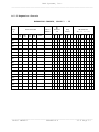
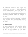
A.2 Configuration When Shipped
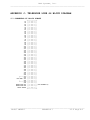
A.2.1 Common Equipment Chassis
COMMON EQUIPMENT CHASSIS
Item Installed
Slot
#
LM
-01
TMS
-03
CID
-06
CC
-15
GND
-18
S#
PID
-23
Other
1
2
3
CND Receiver
-25 (for -06 card)
Ring
Detect
MF
Receiver
-04
4
1
2
3
4
1
2
3
4
5
6
7
8
C1
C2
C3
C4
C5
C6
C7
______________________________________________________________________
Model LMT4911
APPENDIX A
V2.6 Page 20
RAN Systems, Inc.
______________________________________________________________________
A.2.2 Expansion Chassis
EXPANSION CHASSIS, SLOTS 1 - 16
Item Installed
Slot
#
LM
-01
TMS
-03
CID
-06
GND
-18
MF
Receiver
-04
Serial
Number
Other
1
2
3
CND Receiver
-25 (for -06 card)
Ring
Detect
4
1
2
3
4
1
2
3
4
5
6
7
8
E1
E2
E3
E4
E5
E6
E7
E8
E9
E10
E11
E12
E13
E14
E15
E16
______________________________________________________________________
Model LMT4911
APPENDIX A
V2.6 Page 21
RAN Systems, Inc.
______________________________________________________________________
A.3 SITE CONFIGURATION CHART
SITE NAME ________________________________________
CONFIGURATION CHART: LINES 1-20
+----+-----------------------------------+---+-----+-----+-------------------+
|LINE|
LINE NAME
|DID| LOOP| GND |
COMMENTS
|
| # |
|
|START|START|
|
|====|===================================|===|=====|=====|===================|
| 1 |
|
|
|
|
|
+----+-----------------------------------+---+-----+-----+-------------------+
| 2 |
|
|
|
|
|
+----+-----------------------------------+---+-----+-----+-------------------+
| 3 |
|
|
|
|
|
+----+-----------------------------------+---+-----+-----+-------------------+
| 4 |
|
|
|
|
|
+----+-----------------------------------+---+-----+-----+-------------------+
| 5 |
|
|
|
|
|
+----+-----------------------------------+---+-----+-----+-------------------+
| 6 |
|
|
|
|
|
+----+-----------------------------------+---+-----+-----+-------------------+
| 7 |
|
|
|
|
|
+----+-----------------------------------+---+-----+-----+-------------------+
| 8 |
|
|
|
|
|
+----+-----------------------------------+---+-----+-----+-------------------+
| 9 |
|
|
|
|
|
+----+-----------------------------------+---+-----+-----+-------------------+
| 10 |
|
|
|
|
|
+----+-----------------------------------+---+-----+-----+-------------------+
| 11 |
|
|
|
|
|
+----+-----------------------------------+---+-----+-----+-------------------+
| 12 |
|
|
|
|
|
+----+-----------------------------------+---+-----+-----+-------------------+
| 13 |
|
|
|
|
|
+----+-----------------------------------+---+-----+-----+-------------------+
| 14 |
|
|
|
|
|
+----+-----------------------------------+---+-----+-----+-------------------+
| 15 |
|
|
|
|
|
+----+-----------------------------------+---+-----+-----+-------------------+
| 16 |
|
|
|
|
|
+----+-----------------------------------+---+-----+-----+-------------------+
| 17 |
|
|
|
|
|
+----+-----------------------------------+---+-----+-----+-------------------+
| 18 |
|
|
|
|
|
+----+-----------------------------------+---+-----+-----+-------------------+
| 19 |
|
|
|
|
|
+----+-----------------------------------+---+-----+-----+-------------------+
| 20 |
|
|
|
|
|
+----+-----------------------------------+---+-----+-----+-------------------+
______________________________________________________________________
Model LMT4911
APPENDIX A
V2.6 Page 22
RAN Systems, Inc.
______________________________________________________________________
SITE NAME ________________________________________
CONFIGURATION CHART: LINES 21-40
+----+-----------------------------------+---+-----+-----+-------------------+
| 21 |
|
|
|
|
|
+----+-----------------------------------+---+-----+-----+-------------------+
| 22 |
|
|
|
|
|
+----+-----------------------------------+---+-----+-----+-------------------+
| 23 |
|
|
|
|
|
+----+-----------------------------------+---+-----+-----+-------------------+
| 24 |
|
|
|
|
|
+----+-----------------------------------+---+-----+-----+-------------------+
| 25 |
|
|
|
|
|
+----+-----------------------------------+---+-----+-----+-------------------+
| 26 |
|
|
|
|
|
+----+-----------------------------------+---+-----+-----+-------------------+
| 27 |
|
|
|
|
|
+----+-----------------------------------+---+-----+-----+-------------------+
| 28 |
|
|
|
|
|
+----+-----------------------------------+---+-----+-----+-------------------+
| 29 |
|
|
|
|
|
+----+-----------------------------------+---+-----+-----+-------------------+
| 30 |
|
|
|
|
|
+----+-----------------------------------+---+-----+-----+-------------------+
| 31 |
|
|
|
|
|
+----+-----------------------------------+---+-----+-----+-------------------+
| 32 |
|
|
|
|
|
+----+-----------------------------------+---+-----+-----+-------------------+
| 33 |
|
|
|
|
|
+----+-----------------------------------+---+-----+-----+-------------------+
| 34 |
|
|
|
|
|
+----+-----------------------------------+---+-----+-----+-------------------+
| 35 |
|
|
|
|
|
+----+-----------------------------------+---+-----+-----+-------------------+
| 36 |
|
|
|
|
|
+----+-----------------------------------+---+-----+-----+-------------------+
| 37 |
|
|
|
|
|
+----+-----------------------------------+---+-----+-----+-------------------+
| 38 |
|
|
|
|
|
+----+-----------------------------------+---+-----+-----+-------------------+
| 39 |
|
|
|
|
|
+----+-----------------------------------+---+-----+-----+-------------------+
| 40 |
|
|
|
|
|
+----+-----------------------------------+---+-----+-----+-------------------+
______________________________________________________________________
Model LMT4911
APPENDIX A
V2.6 Page 23
RAN Systems, Inc.
______________________________________________________________________
SITE NAME ________________________________________
CONFIGURATION CHART: LINES 41-60
+----+-----------------------------------+---+-----+-----+-------------------+
| 41 |
|
|
|
|
|
+----+-----------------------------------+---+-----+-----+-------------------+
| 42 |
|
|
|
|
|
+----+-----------------------------------+---+-----+-----+-------------------+
| 43 |
|
|
|
|
|
+----+-----------------------------------+---+-----+-----+-------------------+
| 44 |
|
|
|
|
|
+----+-----------------------------------+---+-----+-----+-------------------+
| 45 |
|
|
|
|
|
+----+-----------------------------------+---+-----+-----+-------------------+
| 46 |
|
|
|
|
|
+----+-----------------------------------+---+-----+-----+-------------------+
| 47 |
|
|
|
|
|
+----+-----------------------------------+---+-----+-----+-------------------+
| 48 |
|
|
|
|
|
+----+-----------------------------------+---+-----+-----+-------------------+
| 49 |
|
|
|
|
|
+----+-----------------------------------+---+-----+-----+-------------------+
| 50 |
|
|
|
|
|
+----+-----------------------------------+---+-----+-----+-------------------+
| 51 |
|
|
|
|
|
+----+-----------------------------------+---+-----+-----+-------------------+
| 52 |
|
|
|
|
|
+----+-----------------------------------+---+-----+-----+-------------------+
| 53 |
|
|
|
|
|
+----+-----------------------------------+---+-----+-----+-------------------+
| 54 |
|
|
|
|
|
+----+-----------------------------------+---+-----+-----+-------------------+
| 55 |
|
|
|
|
|
+----+-----------------------------------+---+-----+-----+-------------------+
| 56 |
|
|
|
|
|
+----+-----------------------------------+---+-----+-----+-------------------+
| 57 |
|
|
|
|
|
+----+-----------------------------------+---+-----+-----+-------------------+
| 58 |
|
|
|
|
|
+----+-----------------------------------+---+-----+-----+-------------------+
| 59 |
|
|
|
|
|
+----+-----------------------------------+---+-----+-----+-------------------+
| 60 |
|
|
|
|
|
+----+-----------------------------------+---+-----+-----+-------------------+
______________________________________________________________________
Model LMT4911
APPENDIX A
V2.6 Page 24
RAN Systems, Inc.
______________________________________________________________________
SITE NAME ________________________________________
CONFIGURATION CHART: LINES 61-80
+----+-----------------------------------+---+-----+-----+-------------------+
| 61 |
|
|
|
|
|
+----+-----------------------------------+---+-----+-----+-------------------+
| 62 |
|
|
|
|
|
+----+-----------------------------------+---+-----+-----+-------------------+
| 63 |
|
|
|
|
|
+----+-----------------------------------+---+-----+-----+-------------------+
| 64 |
|
|
|
|
|
+----+-----------------------------------+---+-----+-----+-------------------+
| 65 |
|
|
|
|
|
+----+-----------------------------------+---+-----+-----+-------------------+
| 66 |
|
|
|
|
|
+----+-----------------------------------+---+-----+-----+-------------------+
| 67 |
|
|
|
|
|
+----+-----------------------------------+---+-----+-----+-------------------+
| 68 |
|
|
|
|
|
+----+-----------------------------------+---+-----+-----+-------------------+
| 69 |
|
|
|
|
|
+----+-----------------------------------+---+-----+-----+-------------------+
| 70 |
|
|
|
|
|
+----+-----------------------------------+---+-----+-----+-------------------+
| 71 |
|
|
|
|
|
+----+-----------------------------------+---+-----+-----+-------------------+
| 72 |
|
|
|
|
|
+----+-----------------------------------+---+-----+-----+-------------------+
| 73 |
|
|
|
|
|
+----+-----------------------------------+---+-----+-----+-------------------+
| 74 |
|
|
|
|
|
+----+-----------------------------------+---+-----+-----+-------------------+
| 75 |
|
|
|
|
|
+----+-----------------------------------+---+-----+-----+-------------------+
| 76 |
|
|
|
|
|
+----+-----------------------------------+---+-----+-----+-------------------+
| 77 |
|
|
|
|
|
+----+-----------------------------------+---+-----+-----+-------------------+
| 78 |
|
|
|
|
|
+----+-----------------------------------+---+-----+-----+-------------------+
| 79 |
|
|
|
|
|
+----+-----------------------------------+---+-----+-----+-------------------+
| 80 |
|
|
|
|
|
+----+-----------------------------------+---+-----+-----+-------------------+
______________________________________________________________________
Model LMT4911
APPENDIX A
V2.6 Page 25
RAN Systems, Inc.
______________________________________________________________________
SITE NAME ________________________________________
CONFIGURATION CHART: LINES 81-100
+----+-----------------------------------+---+-----+-----+-------------------+
| 81 |
|
|
|
|
|
+----+-----------------------------------+---+-----+-----+-------------------+
| 82 |
|
|
|
|
|
+----+-----------------------------------+---+-----+-----+-------------------+
| 83 |
|
|
|
|
|
+----+-----------------------------------+---+-----+-----+-------------------+
| 84 |
|
|
|
|
|
+----+-----------------------------------+---+-----+-----+-------------------+
| 85 |
|
|
|
|
|
+----+-----------------------------------+---+-----+-----+-------------------+
| 86 |
|
|
|
|
|
+----+-----------------------------------+---+-----+-----+-------------------+
| 87 |
|
|
|
|
|
+----+-----------------------------------+---+-----+-----+-------------------+
| 88 |
|
|
|
|
|
+----+-----------------------------------+---+-----+-----+-------------------+
| 89 |
|
|
|
|
|
+----+-----------------------------------+---+-----+-----+-------------------+
| 90 |
|
|
|
|
|
+----+-----------------------------------+---+-----+-----+-------------------+
| 91 |
|
|
|
|
|
+----+-----------------------------------+---+-----+-----+-------------------+
| 92 |
|
|
|
|
|
+----+-----------------------------------+---+-----+-----+-------------------+
| 93 |
|
|
|
|
|
+----+-----------------------------------+---+-----+-----+-------------------+
| 94 |
|
|
|
|
|
+----+-----------------------------------+---+-----+-----+-------------------+
| 95 |
|
|
|
|
|
+----+-----------------------------------+---+-----+-----+-------------------+
| 96 |
|
|
|
|
|
+----+-----------------------------------+---+-----+-----+-------------------+
| 97 |
|
|
|
|
|
+----+-----------------------------------+---+-----+-----+-------------------+
| 98 |
|
|
|
|
|
+----+-----------------------------------+---+-----+-----+-------------------+
| 99 |
|
|
|
|
|
+----+-----------------------------------+---+-----+-----+-------------------+
|100 |
|
|
|
|
|
+----+-----------------------------------+---+-----+-----+-------------------+
______________________________________________________________________
Model LMT4911
APPENDIX A
V2.6 Page 26
RAN Systems, Inc.
______________________________________________________________________
APPENDIX B: CONFIGURING THE COMMON EQUIPMENT CHASSIS
The Common Equipment Chassis (Model LMT 4911-00) houses one TMS Module
(-03) and any combination of one to five Standard Line Monitor Cards
(-01), Caller ID Line Monitoring Cards (-06), VF Test/Monitoring
Access Cards (-08) or Ground Start Monitoring Cards (-18).
B.1 Positions Of The Cards In the Common Equip. Chassis
There are six slots in the Common Equipment Chassis, designated C1 to
C6. Cards should be installed in the slots as shown in the following
illustration. Note that when the Expansion Chassis is not used, the
card for lines 17-20 is installed in slot C6. When the Expansion
Chassis is used the Expansion Buffer Card is installed in slot C6 and
the card for lines 17-20 is moved to slot E1 in the Expansion Chassis.
This move does not affect the location of the line inputs on the rear
panel of the Common Equipment Chassis. Lines 17-20 appear on the same
connector and pin numbers regardless of the location of their card.
When Caller ID Cards, which provide eight lines per card, are
employed, up to forty lines may be accommodated within the Common
Equipment Chassis. Lines 21 to 40 are terminated on a second connector
on the rear panel.
Front Panel
+---------------------+
|
|
|=====================|
|=====================|
|=====================|
|=====================|
|=====================|
|=====================|
|
|
|
+------+
|
|
|
|
|
|Remote
|Power |
|
|Reset
|Supply|
|
|Module
|
|
|
|
|
|
|
|
|
|
|
+---------+------+----+
Slot
Slot
Slot
Slot
Slot
Slot
C1:
C2:
C3:
C4:
C5:
C6:
TMS Card (or not used)
Bank 1, Card 1, Lines 1-4 or 1-8
Bank 1, Card 2, Lines 5-8 or 9-16
Bank 1, Card 3, Lines 9-12 or 17-24
Bank 1, Card 4, Lines 13-16 or 25-32
Bank 1, Card 5, Lines 17-20 or 33-40
or Expansion Buffer Card
Top View Of Common Equipment Chassis With Cover Removed
______________________________________________________________________
Model LMT4911
APPENDIX B
V2.6 Page 27
RAN Systems, Inc.
______________________________________________________________________
APPENDIX C: CONFIGURING THE EXPANSION CHASSIS
The Expansion Chassis (Model LMT 4911-02) houses any combination of
one to sixteen Standard Line Monitor Cards (-01), Caller ID Line
Monitoring
Cards (-06), VF Test/Monitoring Access Cards (-08) or
Ground Start Monitoring Cards (-18).
C.1 Positions of the Cards in the Expansion Chassis
There are sixteen slots in the Expansion Chassis, designated E1 to
E16. Cards should be installed in the slots as shown below: Note, if
Caller ID cards
are installed,
each card/slot shown below can
accommodate eight rather than the four lines.
Front Panel
+---------------------+
¦
¦
¦ ------------------- ¦
¦ ------------------- ¦
¦ ------------------- ¦
¦ ------------------- ¦
¦ ------------------- ¦
¦ ------------------- ¦
¦ ------------------- ¦
¦ ------------------- ¦
¦ ------------------- ¦
¦ ------------------- ¦
¦ ------------------- ¦
¦ ------------------- ¦
¦ ------------------- ¦
¦ ------------------- ¦
¦ ------------------- ¦
¦ ------------------- ¦
+---------------------+
Slot
Slot
Slot
Slot
Slot
Slot
Slot
Slot
Slot
Slot
Slot
Slot
Slot
Slot
Slot
Slot
E1:
E2:
E3:
E4:
E5:
E6:
E7:
E8:
E9:
E10:
E11:
E12:
E13:
E14:
E15:
E16:
Bank
Bank
Bank
Bank
Bank
Bank
Bank
Bank
Bank
Bank
Bank
Bank
Bank
Bank
Bank
Bank
1,
2,
2,
2,
2,
2,
3,
3,
3,
3,
3,
4,
4,
4,
4,
4,
Card
Card
Card
Card
Card
Card
Card
Card
Card
Card
Card
Card
Card
Card
Card
Card
5,
1,
2,
3,
4,
5,
1,
2,
3,
4,
5,
1,
2,
3,
4,
5,
Lines
Lines
Lines
Lines
Lines
Lines
Lines
Lines
Lines
Lines
Lines
Lines
Lines
Lines
Lines
Lines
17-20
21-24
25-28
29-32
33-36
37-40
41-44
45-48
49-52
53-56
57-60
61-64
65-68
69-72
73-76
77-80
Top View Of Expansion Chassis With Cover Removed
The addresses that must be set for the Standard Line Monitor Cards,
Caller ID Line Monitor Cards, and VF Test/Monitoring Access Cards
are related
to
the numbers
of
the lines connected to them. All
cards use a
similar
addressing scheme,
and
the DIP switch or
jumper/strap settings required for each card position are given in
Appendices E or F.
______________________________________________________________________
Model LMT4911
APPENDIX C
V2.6 Page 28
RAN Systems, Inc.
______________________________________________________________________
APPENDIX D: CONFIGURING THE TMS MODULE
The
TMS Module, if equipped, is always located in Slot 1 of the
Common Equipment Chassis. There are three DIP switches on the module
which must be set as follows:
SWITCH SW1
---------------------------POSITION #
1 2
3 4
SETTING
OFF ON OFF ON
SWITCH SW2
------------------------------------POSITION #
1
2
3
4
5
6
SETTING
OFF OFF OFF OFF OFF OFF
SWITCH SW3
------------------------------------POSITION #
1
2
3
4
5
6
SETTING
OFF OFF OFF OFF OFF OFF
+---------------------------------------------------------------+
¦
¦
¦
SW1
¦
¦
+----+
¦
¦
SW2
¦1234¦
¦
¦
+--------+ +----+
¦
¦
¦12345678¦
¦
¦
+--------+
¦
¦
¦
¦
SW3
¦
¦
+--------+
¦
¦
¦12345678¦
¦
¦
+--------+
¦
¦
¦
+--------------------------------+
¦
¦
¦
+----+
+---------+
¦
¦
¦
¦
+---------------+
TMS MODULE DIP SWITCH LOCATIONS
______________________________________________________________________
Model LMT4911
APPENDIX D
V2.6 Page 29
RAN Systems, Inc.
______________________________________________________________________
APPENDIX E: CONFIGURING THE LINE CARDS
E.1 Standard
Access Cards
Line
Monitoring,
Ground
Start
and
VF
Test/Monitoring
There are three DIP switches on each Standard Line Monitoring Card and
Ground Start
Card designated SW1, SW2, and SW3. The
VF
Test/Monitoring Access Card switches are identical except that switch
SW2 is omitted. The switch
designations and settings are identical
for all three types of cards. There are also Ring Detect jumpers
on both the Standard Line Monitor and Ground Start Line Cards.
LAYOUT OF STANDARD, GROUND START AND VF TEST/MONITORING CARDS
Ring
Detect
1
123
...
Ring
Detect
2
Ring
Detect
3
123
...
123
...
Ring
Detect
4
123
...
SW3
1st MF
2nd MF
3rd MF
4th MF
12345
SW2
SW1
12345678
1234
E.1.1 DIP Switch Settings
Set DIP switches SW1 and SW3 for these line cards as covered on Chart
F1 of APPENDIX F. The chart also gives the switch functions.
Set DIP switch SW2 as covered in Paragraph E.3 of this appendix.
______________________________________________________________________
Model LMT4911
APPENDIX E
V2.6 Page 30
RAN Systems, Inc.
______________________________________________________________________
E.1.2 Programming Strap Configuration
Configure the Standard Line Monitor Card for line types as follows:
Loop start:
Jump 1-2 (Ring Detector ON), Remove MF Receiver
DID:
Jump 2-3 (Ring Detector OFF), Install MF Receiver
NOTE: If MF Receivers are used on a card, there must be an
MF Receiver in location 1. Locations 2-4 can be any
configuration. If Tone Position Identifier capability is
provided, the Tone Position Identifier Receiver must be
inserted in the MF Receiver socket in addition to the MF
Receiver itself per APPENDIX W.
E.2 Caller ID Line Monitoring Cards
E.2.1 Card Configuration
The
Caller
ID Line Monitoring Card LMT 4911-06 is
actually
two
independent four-circuit line monitors on a single card. The monitors
are designated
'A' and 'B'.
Each has its own input cable and an
independent set of Bank and Card programming jumpers, and may be set
to any Bank (1 thru 6) and Card (1 thru 5) in the system. The two
monitor cards must never be set to the same combination of bank and
card. They may, however, both be set to the same bank OR the same
card.
The card is equipped with a single DIP switch (SW1) which is used to
determine whether the card functions as the master, or as a slave.
Set this switch as covered in Paragraph E.3 of this appendix.
The card is also equipped with eight sockets which accept CND
Receivers (-25), and eight
sockets which accept Tone Position
Identifier Receivers (-26). Refer to the appropriate appendices for
information on the installation of these
devices, if required. No
programming straps are associated with these devices.
______________________________________________________________________
Model LMT4911
APPENDIX E
V2.6 Page 31
RAN Systems, Inc.
______________________________________________________________________
LAYOUT OF CALLER ID LINE MONITORING CARD
CONNECTOR J1
BANK 'A' LINES
(four)
CONNECTOR J2
BANK 'B' LINES
(four)
Tone Position Receiver
Chip LMT-4911-26
BANKS
A
B
°° 1 °°
°° 2 °°
°° 3 °°
°° 4 °°
°° 5 °°
°° 6 °°
°° 7 °°
°° 8 °°
CND Receiver
LMT-4911-25
1
2
3
CARD
A
1 2 4
° ° °
° ° °
CARD
B
1 2 4
° ° °
° ° °
SW1
4
5
6
7
8
Line #
E.2.2 Programming Strap Configuration
There are two independent sets of programming straps on the card, one
for each four line monitor card. Each pair consists of a Bank Set
and a Card Set and are labelled 'A' or 'B'.
E.2.2.1 Configuring the Bank Programming Straps
Each bank strap consists of a set of eight pin pairs, one for the 'A'
bank, and one for the 'B' bank. The pairs are numbered 1 through
8. Place a single strap horizontally across the pair corresponding
to the desired bank. If a four line monitor is to remain unused, do
not strap any bank.
______________________________________________________________________
Model LMT4911
APPENDIX E
V2.6 Page 32
RAN Systems, Inc.
______________________________________________________________________
E.2.2.2 Configuring the Card Programming Straps
Each
strap consists of a set of three pin pairs, one for the 'A'
CARD, and one for the 'B' CARD. The card selected is one greater
than the numerical value (from zero to four) set by placing from 0
to 2 straps across the pin pairs. The pairs are numbered 1,2 and 4
in binary fashion. The number programmed is the sum of the values of
the straps placed across the pin pairs, as shown
in the following
table.
+----------------------+
¦ CARD ¦
STRAP #
¦
¦NUMBER +--------------¦
¦
¦ 1 ¦ 2 ¦ 4 ¦
+-------+----+----+----¦
¦
1
¦out ¦out ¦out ¦
+-------+----+----+----¦
¦
2
¦ IN ¦out ¦out ¦
+-------+----+----+----¦
¦
3
¦out ¦ IN ¦out ¦
+-------+----+----+----¦
¦
4
¦ IN ¦ IN ¦out ¦
+-------+----+----+----¦
¦
5
¦out ¦out ¦ IN ¦
+----------------------+
E.2.2.3 Line Number vs Strap Chart
As indicated above, two jumper/straps must be placed in order to
assign each four line circuit group to a specific bank of line
terminations on the
Caller ID card. One of these jumper straps is
placed on the strap field marked BANKS A - B and the second
jumper/strap is placed on one of the two strap fields marked CARD A
or CARD B. When straps are placed in the BANK A field the related
jumper strap must be placed in the CARD A field and when
a
jumper/strap
is
placed in the BANK B field the
corresponding
jumper/strap must be placed in the CARD B field.
Chart F2 in
APPENDIX F shows the required strapping for each possible four line
group. In actual operation, a mix of Caller ID and Standard Line
Cards is anticipated
and
therefore
all
line numbers
shown in
Chart F2 will not necessarily be accommodated by Caller ID Cards.
Nevertheless, the line numbers assigned to Caller ID Cards should be
strapped as shown in Chart F2.
______________________________________________________________________
Model LMT4911
APPENDIX E
V2.6 Page 33
RAN Systems, Inc.
______________________________________________________________________
E.3 Master-Slave DIP Switch SW2 Settings (all card types)
On all line cards, DIP switch SW2 sets the Master-Slave function. One
card in the system has to be set as Master. All others MUST be set
as Slaves.
Set the Master-Slave function on DIP switch SW2 as follows:
MASTER
+----------------------------------------------------+
¦ POSITION # ¦ 1 ¦ 2 ¦ 3 ¦ 4 ¦ 5 ¦ 6 ¦ 7 ¦ 8 ¦
+------------+----+----+----+----+----+----+----+----¦
¦ SETTING
¦off ¦off ¦off ¦ ON ¦off ¦off ¦off ¦ - ¦
+----------------------------------------------------+
NOTE: Position 8 may not be equipped. If present, it is not
functional and may be in either setting.
SLAVE
+----------------------------------------------------+
¦ POSITION # ¦ 1 ¦ 2 ¦ 3 ¦ 4 ¦ 5 ¦ 6 ¦ 7 ¦ 8 ¦
+------------+----+----+----+----+----+----+----+----¦
¦ SETTING
¦off ¦off ¦off ¦off ¦off ¦off ¦ ON ¦ - ¦
+----------------------------------------------------+
NOTE: On Caller ID Line Cards, the Master/Slave switch is a seven
position DIP switch with the same switch assignments.
______________________________________________________________________
Model LMT4911
APPENDIX E
V2.6 Page 34
RAN Systems, Inc.
______________________________________________________________________
APPENDIX F: CARD DIP SWITCH SETTINGS
Chart F1 - Standard Line Monitoring Card DIP Switch Settings
On = switch position ON, x = switch position OFF
+-----------------------------------------------+
¦LINES ¦SLOT ¦BNK¦CRD¦ SW1-CARD# ¦ SW3-BANK#
¦
¦
¦
¦
¦
¦-----------+--------------¦
¦
¦ #
¦ # ¦ # ¦ 1¦ 2¦ 3¦ 4¦ 1¦ 2¦ 3¦ 4¦ 5¦
¦------+-----+---+---+--+--+--+--+--+--+--+--+--¦
¦
1-4¦ C2 ¦ 1 ¦ 1 ¦On¦On¦On¦On¦ x¦On¦ x¦ x¦ x¦
+------+-----+---+---+--+--+--+--+--+--+--+--+--¦
¦
5-8¦ C3 ¦ 1 ¦ 2 ¦On¦On¦On¦ x¦ x¦On¦ x¦ x¦ x¦
+------+-----+---+---+--+--+--+--+--+--+--+--+--¦
¦ 9-12¦ C4 ¦ 1 ¦ 3 ¦On¦On¦ x¦On¦ x¦On¦ x¦ x¦ x¦
+------+-----+---+---+--+--+--+--+--+--+--+--+--¦
¦ 13-16¦ C5 ¦ 1 ¦ 4 ¦On¦On¦ x¦ x¦ x¦On¦ x¦ x¦ x¦
+------+-----+---+---+--+--+--+--+--+--+--+--+--¦
¦ 17-20¦C6/E1¦ 1 ¦ 5 ¦On¦ x¦On¦On¦ x¦On¦ x¦ x¦ x¦
+------+-----+---+---+--+--+--+--+--+--+--+--+--¦
¦ 21-24¦ E2 ¦ 2 ¦ 1 ¦On¦On¦On¦On¦ x¦ x¦On¦ x¦ x¦
+------+-----+---+---+--+--+--+--+--+--+--+--+--¦
¦ 25-28¦ E3 ¦ 2 ¦ 2 ¦On¦On¦On¦ x¦ x¦ x¦On¦ x¦ x¦
+------+-----+---+---+--+--+--+--+--+--+--+--+--¦
¦ 29-32¦ E4 ¦ 2 ¦ 3 ¦On¦On¦ x¦On¦ x¦ x¦On¦ x¦ x¦
+------+-----+---+---+--+--+--+--+--+--+--+--+--¦
¦ 33-36¦ E5 ¦ 2 ¦ 4 ¦On¦On¦ x¦ x¦ x¦ x¦On¦ x¦ x¦
+------+-----+---+---+--+--+--+--+--+--+--+--+--¦
¦ 37-40¦ E6 ¦ 2 ¦ 5 ¦On¦ x¦On¦On¦ x¦ x¦On¦ x¦ x¦
+------+-----+---+---+--+--+--+--+--+--+--+--+--¦
¦ 41-44¦ E7 ¦ 3 ¦ 1 ¦On¦On¦On¦On¦ x¦ x¦ x¦On¦ x¦
+------+-----+---+---+--+--+--+--+--+--+--+--+--¦
¦ 45-48¦ E8 ¦ 3 ¦ 2 ¦On¦On¦On¦ x¦ x¦ x¦ x¦On¦ x¦
+------+-----+---+---+--+--+--+--+--+--+--+--+--¦
¦ 49-52¦ E9 ¦ 3 ¦ 3 ¦On¦On¦ x¦On¦ x¦ x¦ x¦On¦ x¦
+------+-----+---+---+--+--+--+--+--+--+--+--+--¦
¦ 53-56¦E10 ¦ 3 ¦ 4 ¦On¦On¦ x¦ x¦ x¦ x¦ x¦On¦ x¦
+------+-----+---+---+--+--+--+--+--+--+--+--+--¦
¦ 57-60¦E11 ¦ 3 ¦ 5 ¦On¦ x¦On¦On¦ x¦ x¦ x¦On¦ x¦
+------+-----+---+---+--+--+--+--+--+--+--+--+--¦
¦ 61-64¦E12 ¦ 4 ¦ 1 ¦On¦On¦On¦On¦ x¦ x¦ x¦ x¦On¦
+------+-----+---+---+--+--+--+--+--+--+--+--+--¦
¦ 65-68¦E13 ¦ 4 ¦ 2 ¦On¦On¦On¦ x¦ x¦ x¦ x¦ x¦On¦
+------+-----+---+---+--+--+--+--+--+--+--+--+--¦
¦ 69-72¦E14 ¦ 4 ¦ 3 ¦On¦On¦ x¦On¦ x¦ x¦ x¦ x¦On¦
+------+-----+---+---+--+--+--+--+--+--+--+--+--¦
¦ 73-76¦E15 ¦ 4 ¦ 4 ¦On¦On¦ x¦ x¦ x¦ x¦ x¦ x¦On¦
+------+-----+---+---+--+--+--+--¦--+--+--+--+--¦
¦ 77-80¦E16 ¦ 4 ¦ 5 ¦On¦ x¦On¦On¦ x¦ x¦ x¦ x¦On¦
+------+-----+---+---+--------------------------¦
______________________________________________________________________
Model LMT4911
APPENDIX F
V2.6 Page 35
RAN Systems, Inc.
______________________________________________________________________
Chart F2
Caller ID Line Monitoring Card Address STRAP/JUMPER Settings
+----------------------¦ LINES ¦BANK¦CARD¦JUMP¦
¦
¦ # ¦
¦
¦
¦
¦PINS¦ # ¦PINS¦
¦-------+----+----+----+
¦ 1-4 ¦ A1 ¦ A ¦NONE¦
+-------+----+----+----+
¦ 5-8 ¦ B1 ¦ B ¦ 1 ¦
+-------+----+----+----+
¦ 9-12 ¦ A1 ¦ A ¦ 2 ¦
+-------+----+----+----+
¦ 13-16 ¦ B1 ¦ B ¦1-2 ¦
+-------+----+----+----+
¦ 17-20 ¦ A1 ¦ A ¦ 4 ¦
+-------+----+----+----+
¦ 21-24 ¦ B2 ¦ B ¦NONE¦
+-------+----+----+----+
¦ 25-28 ¦ A2 ¦ A ¦ 1 ¦
+-------+----+----+----+
¦ 29-32 ¦ B2 ¦ B ¦ 2 ¦
+-------+----+----+----+
¦ 33-36 ¦ A2 ¦ A ¦1-2 ¦
+-------+----+----+----+
¦ 37-40 ¦ B2 ¦ B ¦ 4 ¦
+-------+----+----+----+
¦ 41-44 ¦ A3 ¦ A ¦NONE¦
+-------+----+----+----+
¦ 45-48 ¦ B3 ¦ B ¦ 1 ¦
+-------+----+----+----+
¦ 49-52 ¦ A3 ¦ A ¦ 2 ¦
+-------+----+----+----+
¦ 53-56 ¦ B3 ¦ B ¦1-2 ¦
+-------+----+----+----+
¦ 57-60 ¦ A3 ¦ A ¦ 4 ¦
+-------+----+----+----+
- BANK # PINS
- CARD #
- JUMP PINS
+----------------------¦ LINES ¦BANK¦CARD¦JUMP¦
¦
¦ # ¦
¦
¦
¦
¦PINS¦ # ¦PINS¦
¦-------+----+----+----+
¦ 61-64 ¦ B4 ¦ B ¦NONE¦
+-------+----+----+----+
¦ 65-68 ¦ A4 ¦ A ¦ 1 ¦
+-------+----+----+----+
¦ 69-72 ¦ B4 ¦ B ¦ 2 ¦
+-------+----+----+----+
¦ 73-76 ¦ A4 ¦ A ¦1-2 ¦
+-------+----+----+----+
¦ 77-80 ¦ B4 ¦ B ¦ 4 ¦
+-------+----+----+----+
¦ 81-84 ¦ A5 ¦ A ¦NONE¦
+-------+----+----+----+
¦ 85-88 ¦ B5 ¦ B ¦ 1 ¦
+-------+----+----+----+
¦ 89-92 ¦ A5 ¦ A ¦ 2 ¦
+-------+----+----+----+
¦ 93-96 ¦ B5 ¦ B ¦1-2 ¦
+-------+----+----+----+
¦ 97-100¦ A5 ¦ A ¦ 4 ¦
+-------+----+----+----+
= BANKS STRAP FIELD AND PIN TO BE JUMPERED
= THE A OR B CARD TO BE JUMPERED
= THE PINS CARD A OR B TO BE JUMPERED
______________________________________________________________________
Model LMT4911
APPENDIX F
V2.6 Page 36
RAN Systems, Inc.
______________________________________________________________________
APPENDIX G: REMOTE RESET CONTROL
A Line Logg-R equipped with the remote reset module can be connected
in
such a
manner that a selected telephone line serving
the
facility in which it is located may be used to reset the Line LoggR's computer.
G.1 RESET COMMAND SEQUENCE
The DTMF reset string format is: #XXX*1
Where:
#
= Clear Buffer, address follows
XXX = 3 digit address (000-999)
(as set by DIP switches inside the Line Logg-R)
*
= End of Address
1
= Reset Command
(Pound [#] symbol followed by 3 ADDRESS numbers
(000 to 999), followed by star [*] symbol,
followed by a the number one [1])
G.2 CONNECTING THE TELEPHONE LINE
The remote reset module input consists of a VF pair that may be
connected across
any telephone line in the facility that normally
carries voice traffic. The unit may be reset by placing a call to
that line and, once the call is answered, keying in a special DTMF
code. The line used may be connected to an individual's telephone
instrument or an answering machine. A FAX or modem line may not be
used. The line may be one that is also being monitored by the Line
Logg-R.
The VF pair is a monitor only pair, with a VF impedance of greater
that 10,000 ohms, a ringer equivalent of 0, and a DC resistance of
greater than 2 megohms. Thus, the Line Logg-R does not interfere with
normal traffic on the line,
but monitors
for the specific DTMF
string.
When the string is received the
Line Logg-R will reset
itself unconditionally without disturbing the traffic on the pair.
The reset is hardware induced, and is independent of the state of the
Line Logg-R's computer.
______________________________________________________________________
Model LMT4911
APPENDIX G
V2.6 Page 37
RAN Systems, Inc.
______________________________________________________________________
The VF pair is connected to pins 24 and 49 or the Line Logg-R's input
connector, and appears on the Type 66 block as pair 24, which may be
strapped across any
line, as desired.
TIP/RING polarity does not
have to be maintained,
and any
form of signaling may be used, as
long as the DTMF signals generated by the remote caller appear on
the pair.
G.3 SETTING THE ADDRESS
NOTE
Line Logg-Rs are shipped with the address set to
911. If you desire a different address always turn
off
the power
to
the
Line Logg-R before
changing the DIP switches.
The Line Logg-R
reads
the
address
DIP switches
on power-up.
Upon application of power,
the reset module's
circuitry goes through an initializing routine to
"learn" its address.
The address cannot be
changed without removal and reapplication of
power.
To set the address, first remove the top cover of the Line Logg-R.
The
Remote Reset Module's PC
board is now accessible at the left
hand side of the unit (as viewed
from the
rear), adjacent to the
rear panel. Two DIP switches, with a total
of
12 poles,
will be
seen.
The twelve poles are used to select three
4-digit
BCD
numbers.
The bit values and digit values of each pole are screened
onto the PC board.
The address digits are coded in BCD (binary coded decimal). In this
type of coding, each decimal digit of the address (there are three,
0 to 9) is coded separately with four poles of the switch. The four
poles are weighted 8-4-2-1. A pole counts when it is in the off
position.
NOTE
A zero in any digit is coded 1010.
For example: To select 379, the corresponding BCD codes are
(3), 0111 (7), 1001 (9). Proceed as follows:
0011
______________________________________________________________________
Model LMT4911
APPENDIX G
V2.6 Page 38
RAN Systems, Inc.
______________________________________________________________________
To set the most significant digit (hundreds) of the address, "3" in
the this example, the four poles of the DIP switches that comprise
the 100's digit should be set to:
Bit
Bit
Bit
Bit
value
value
value
value
8
4
2
1
-
ON
ON
OFF
OFF
= 0
= 0
= 2
= 1
--3
Similarly,
to
set the "tens" digit of the address, "7" in the
example, the four poles of the DIP switches that comprise the 10's
digit should be set to:
Bit
Bit
Bit
Bit
value
value
value
value
8
4
2
1
-
ON
OFF
OFF
OFF
= 0
= 4
= 2
= 1
--7
Finally,
to set the "units" digit of the address,
"9" in this
example,
the four poles of the DIP switches that comprise the 1's
digit should be set to:
Bit
Bit
Bit
Bit
value
value
value
value
8
4
2
1
-
OFF
ON
ON
OFF
= 8
= 0
= 0
= 1
--9
On all switches, the bit value is added by setting the switch handle
to the "OFF" position. Conversely, zero is added when the handle
placed in the "ON" position.
Once the address is set, replace the cover before connecting the
power.
______________________________________________________________________
Model LMT4911
APPENDIX G
V2.6 Page 39
RAN Systems, Inc.
______________________________________________________________________
APPENDIX H: MODEMS
RAN Systems recommends using modems that are compatible with the Hayes
Command set. Do not use modems that auto-baud (eg. a 2400 baud modem
that drops to 1200 baud when noise is detected on the line). The LL
(Line Logg-R) operates at a fixed baud rate and will not follow such
changes.
When connecting a modem to a LL, a “straight” 25 pin RS232 cable
should be used between the LL COM (communication) port and the
attached modem.
In software versions 1.42 or higher, the LL can be user programmed to
output unique modem initialization strings on each COM port. The LL
initializes modems at power-up or by using the “SINT” command. This
replaces the fixed modem initialization string that was previously
transmitted out COM1 and COM2 at LL power-up.
The default settings
are No initialization strings being sent on any LL COM ports.
The LL modem initialization strings are displayed using the DMDM
(Display MoDeM) command.
DMDM
The LL modem string is set using the SMDM (Set MoDeM) command.
SMDM 1
1 AT&F,S0=1,E0Q1
2
2 AT&F,ATS0=1,ATE0Q1
3
3 AT&F,ATS0=1,ATE0Q1
where:
1, 2
AT
&F
S0=1
E0
Q1
,
and 3 are the COM port numbers
- Hayes attention command
- Loads factory Generic Template
- Enables Automatic Answer on first ring
- Echo Off
- Quiet Mode: No result codes
- 5 second pause between commands
______________________________________________________________________
Model LMT4911
APPENDIX H
V2.6 Page 40
RAN Systems, Inc.
______________________________________________________________________
The previous example “SMDM 1” does not have a modem string specified,
therefore the modem init string for COM1 will be cleared. When a “,”
is used, a 5 second pause will occur and then the command immediately
following the pause will automatically be issued with the “AT” in
front of the command.
The modem init string “AT&F,S0=1,E0Q1” is a
setting that allows the LL to communicate with most Hayes compatible
modems.
The setting of the modem string with SMDM does not transmit the string
out the COM port. The LL initializes modems at power-up or by using
the “SINT” command.
The LL modem init string can be sent using the SINT (Set INiT string)
command.
SINT 1
2
3
where:
1, 2 and 3 are the COM port numbers.
Also, the attached modem will be initialized at LL Power-up.
The
correct procedure for Powering-up a LL with modems attached to its COM
port(s) is as follows:
1) Power-down the LL.
2) Power-down the attached modem(s).
3) Power-up the attached modem(s).
4) Power-up the LL.
______________________________________________________________________
Model LMT4911
APPENDIX H
V2.6 Page 41
RAN Systems, Inc.
______________________________________________________________________
APPENDIX I: RETROFIT FOR EXPANSION CHASSIS
INSTALLATION
I.1 Adding an Expansion Chassis
When an Expansion Chassis is added to an existing Common Equipment
Chassis, the Common Equipment Chassis must be modified to accept the
Expansion Chassis connections as follows:
Required Parts:
-
(1)
(1)
(1)
(1)
(1)
(1)
(1)
(1)
(1)
Main Chassis Rear Power Extender Assembly
Four Conductor Power Cable(9402B09)
50 Pin Ribbon Signal Cable(9402B04)
20 Pin Ribbon Control Cable(9402B03)
Buffer Card(9212B04)
66 Block for each new group of 20 lines to be added
6/32 x 1/2 screws
#6 star washer
6/32 hex nut
I.2 INSTALLATION PROCEDURE
1.
Power down Common Equipment Chassis
2.
Remove top covers from Common Equipment and Expansion Chassis
3.
If there is a line card in slot#6 of the main chassis, remove
it
and place it in slot E1 of the Expansion Chassis per
APPENDIX C.
4.
Install the Buffer Card in slot C6 of the main chassis
5.
Remove the slot cover located on the rear panel of
chassis next to the power switch.
6.
Attach the 50 pin Signal cable to the Buffer card in the main
chassis. Run the cable along the power supply and out of the
hole revealed by the removal of the slot cover.
the
main
______________________________________________________________________
Model LMT4911
APPENDIX I
V2.6 Page 42
RAN Systems, Inc.
______________________________________________________________________
7.
Install the rear power extender assembly in place of the slot
cover. The notch on the rear power extender should face the
right edge of the back panel. Use the #6 screws to secure the
power extender. Connect the ground cable to the back of the top
screw of the rear power assembly with the lock washer and hex
nut.
8.
Connect the internal rear power extender cable to the main
chassis power supply.
9.
Replace the main chassis top cover.
10. Set the expansion chassis on top of the main chassis with
rear panels facing towards you.
11. Connect the four conductor power cable to the
extender on both the main and expansion chassis.
rear
both
power
12. Connect the 50 pin Signal Cable between the two chassis.
13. Connect the 20 pin Control cable between the two chassis.
14. Verify/change
the configuration of the line cards
expansion chassis per APPENDICES C and E.
in
the
15. Replace the top cover of the expansion chassis.
16. Power up the main chassis. The power lights on
should light.
both
chassis
17. Connect the 25 pair VF cable between the expansion chassis' line
connector and the new 66 block line terminations.
18. Configure
the Line Logg-R's database for the
additional
lines
per Section 4.0 of the "Installation and Maintenance
Manual".
______________________________________________________________________
Model LMT4911
APPENDIX I
V2.6 Page 43
RAN Systems, Inc.
______________________________________________________________________
APPENDIX J: TELEPHONE LINE 66 BLOCK DIAGRAM
J.1 CONNECTOR 66 BLOCK PINOUT
+-------------+
1T ¦ ¦ = = = = ¦ ¦
1R ¦ ¦ = = = = ¦ ¦
2T ¦ ¦ = = = = ¦ ¦
2R ¦ ¦ = = = = ¦ ¦
3T ¦ ¦ = = = = ¦ ¦
3R ¦ ¦ = = = = ¦ ¦
4T ¦ ¦ = = = = ¦ ¦
4R ¦ ¦ = = = = ¦ ¦
5T ¦ ¦ = = = = ¦ ¦
5R ¦ ¦ = = = = ¦ ¦
6T ¦ ¦ = = = = ¦ ¦
6R ¦ ¦ = = = = ¦ ¦
7T ¦ ¦ = = = = ¦ ¦
7R ¦ ¦ = = = = ¦ ¦
8T ¦ ¦ = = = = ¦ ¦
8R ¦ ¦ = = = = ¦ ¦
9T ¦ ¦ = = = = ¦ ¦
9R ¦ ¦ = = = = ¦ ¦
10T ¦ ¦ = = = = ¦ ¦
10R ¦ ¦ = = = = ¦ ¦
11T ¦ ¦ = = = = ¦ ¦
11R ¦ ¦ = = = = ¦ ¦
12T ¦ ¦ = = = = ¦ ¦
12R ¦ ¦ = = = = ¦ ¦
13T ¦ ¦ = = = = ¦ ¦
13R ¦ ¦ = = = = ¦ ¦
14T ¦ ¦ = = = = ¦ ¦
14R ¦ ¦ = = = = ¦ ¦
15T ¦ ¦ = = = = ¦ ¦
15R ¦ ¦ = = = = ¦ ¦
16T ¦ ¦ = = = = ¦ ¦
16R ¦ ¦ = = = = ¦ ¦
17T ¦ ¦ = = = = ¦ ¦
18R ¦ ¦ = = = = ¦ ¦
18T ¦ ¦ = = = = ¦ ¦
18R ¦ ¦ = = = = ¦ ¦
19T ¦ ¦ = = = = ¦ ¦
19R ¦ ¦ = = = = ¦ ¦
20T ¦ ¦ = = = = ¦ ¦
20R ¦ ¦ = = = = ¦ ¦
+----- 21T-¦ ¦ = = = = ¦ ¦
¦
21R ¦ ¦ = = = = ¦ ¦
NOT USED 22T ¦ ¦ = = = = ¦ ¦
¦
22R ¦ ¦ = = = = ¦ ¦
+----- 23T-¦ ¦ = = = = ¦ ¦
23R ¦ ¦ = = = = ¦ ¦
RESET PAIR 24T ¦ ¦ = = = = ¦ ¦(See APPENDIX G)
RESET PAIR 24R ¦ ¦ = = = = ¦ ¦
TELCO GROUND ¦ ¦ = = = = ¦ ¦
+-------------+
______________________________________________________________________
Model LMT4911
APPENDIX J
V2.6 Page 44
RAN Systems, Inc.
______________________________________________________________________
APPENDIX K: DIRECT PAIR CONNECTION DIAGRAM
K.1 Direct Pair Connection Diagram
The Line Logg-R may also be connected directly across the lines to
be monitored, although this method of connection is not recommended.
Obtain a suitable cable equipped with a standard 25 pair male ribbon
connector at the Line Logg-R end, and connect the lines as follows
(Note: pins 25 and 50
should be connected to the local telephone
ground.)
+--------------++--------------++--------------++--------------+
¦LINE #¦ T ¦ R ¦¦LINE #¦ T ¦ R ¦¦LINE #¦ T ¦ R ¦¦LINE #¦ T ¦ R ¦
¦------¦---¦---¦¦------¦---¦---¦¦------¦---¦---¦¦------¦---¦---¦
¦
1 ¦ 26¦ 1 ¦¦
6 ¦ 31¦ 6 ¦¦ 11 ¦ 36¦ 11¦¦ 16 ¦ 41¦ 16¦
+------+---+---¦+------+---+---¦+------+---+---¦+------+---+---¦
¦
2 ¦ 27¦ 2 ¦¦
7 ¦ 32¦ 7 ¦¦ 12 ¦ 37¦ 12¦¦ 17 ¦ 42¦ 17¦
+------+---+---¦+------+---+---¦+------+---+---¦+------+---+---¦
¦
3 ¦ 28¦ 3 ¦¦
8 ¦ 33¦ 8 ¦¦ 13 ¦ 38¦ 13¦¦ 18 ¦ 43¦ 18¦
+------+---+---¦+------+---+---¦+------+---+---¦+------+---+---¦
¦
4 ¦ 29¦ 4 ¦¦
9 ¦ 34¦ 9 ¦¦ 14 ¦ 39¦ 14¦¦ 19 ¦ 44¦ 19¦
+------+---+---¦+------+---+---¦+------+---+---¦+------+---+---¦
¦
5 ¦ 30¦ 5 ¦¦ 10 ¦ 35¦ 10¦¦ 15 ¦ 40¦ 15¦¦ 20 ¦ 45¦ 20¦
+--------------++--------------++--------------++------+---+---¦
¦RESET ¦ 49¦ 24¦(See APPENDIX G)
+------+---+---¦
¦GROUND¦ 50¦ 25¦
+--------------+
______________________________________________________________________
Model LMT4911
APPENDIX K
V2.6 Page 45
RAN Systems, Inc.
______________________________________________________________________
APPENDIX L: LINE LOGG-R NETWORK SECURITY SYSTEM
The
Network Security System protects the Line Logg-R from
unauthorized
local and
remote user access.
To operate the Line
Logg-R command set, a user must have an account (assigned user number
and log on password). These can only be assigned by the Superuser
(SU) or System Manager (SM) via a set of password control commands.
To
additionally guard against unauthorized entry, when no user is
logged
on, no
indication of log on requirements are sent to the
terminal device.
Similarly, entry of an incorrect password does not
generate any such indication.
Internal security is provided by restricting the commands that can be
invoked by each user, according to the responsibility level assigned
to the user. Each user can be assigned an individual set of commands.
L.1 Initial Security System Configuration
When the Line Logg-R is shipped the security system is configured as
follows:
1.
Only the Superuser (User
accounts are active.
01)
and
System
Manager
(User
02)
2.
The SU's initial password is 'SUPERUSER'.
3.
The SM's initial password is 'SYSTEM MANAGER'.
4.
The SU has the capability of using any command unless a command
was disabled by the SU with the SUSR command.
5.
The set of allowed commands for the SM is restricted. The
set is sufficient for most applications, and can be expanded
or restricted
by the SU if required. The set of allowed
commands, which are stored in the software, is given in
APPENDIX M.
6.
The
set
of allowed commands for all other users
(when
enabled) is restricted to a minimum. The set can be expanded
or restricted further by the SU. The list of allowed commands,
which are stored in the software, is given in a later section
of this appendix.
______________________________________________________________________
Model LMT4911
APPENDIX L
V2.6 Page 46
RAN Systems, Inc.
______________________________________________________________________
L.2 Logging On
Initially, only the SU or SM can log on. The SU and SM can then
activate (open accounts for) new users as required. As they open
accounts for others the list expands. Any user of any level can log
on to either port (COM1 or COM2),
and both
ports can be used
simultaneously (the same user may even log on to
both ports
simultaneously, if necessary).
The Set Log On (SLOG) command is used to log on the system. This is
the only command the Network Security System will accept from an idle
terminal device.
=>SLOG nn
nn
01
02
03-20
=
=
=
=
User number (01-20)
Superuser
System Manager
Other users
A user desiring to log on sees a prompt '=>', and would enter
following (SU is illustrated):
the
=>SLOG 01
The reply is:
PASSWORD?
The user then types his password (in this case "SUPERUSER").
The
password must be 8-16 characters long (No Spaces) and all characters
used must be printable. The password is not echoed to the screen.
Case is ignored. If the password is correct the Line Logg-R replies
with:
WELCOME TO THE LINE LOGG-R SYSTEM
=>
If the password is incorrect, the reply is:
COMMAND ERROR:
System Access Denied
=>
______________________________________________________________________
Model LMT4911
APPENDIX L
V2.6 Page 47
RAN Systems, Inc.
______________________________________________________________________
L.3 Logging Off
The Set Log Out (SOUT) command is used to log off the system. The user
enters:
=>SOUT
The reply is:
LINE LOGG-R SYSTEM LOG OFF
=>
L.4 Activating New Users
New users can only be activated by the SU or the SM.
The SU can
activate (and deactivate) all users except himself (the SU can never
be deactivated). The SM can activate or deactivate all users except
the SU and SM.
To
activate
a
new user, the SU or
SM must first select
an
inactive
user number.
This is best done by invoking the Display
Active User (DAUS) command to display a list of all assigned user
accounts on the system and selecting the lowest unused number. Next,
a password for the new user should be selected. The password selected
should be new and original. The SU or SM must not assign temporary
trivial passwords,
such
as 'USER #10' or 'PASSWORD', since this
exposes the system to risk until the new user changes his password.
The new user is then activated by invoking the Set Password Command
(SPWD), and assigning the password to the selected user number.
L.5 Changing User Passwords
L.5.1 Superuser
The Superuser (SU) can change his own and all other passwords.
The
Superuser's password is active at start up and has an initial password
of
'SUPERUSER'.
As stated earlier,
the SU password should be
changed immediately after initial log on.
The SU must be logged on
before a password change can occur.
To
change a password, the
Superuser must invoke the Set Password (SPWD) command.
______________________________________________________________________
Model LMT4911
APPENDIX L
V2.6 Page 48
RAN Systems, Inc.
______________________________________________________________________
The
SU need only know the user number to be changed and his own
password. He then invokes the Set Password (SPWD) command:
=>SPWD nn
nn = User number (01-20)
01 = Superuser
02 = System Manager
03-20 = Other users
If the superuser is changing their own password, the following prompts
will be received:
=>OLD PASSWORD?
=>NEW PASSWORD?
=>VERIFY PASSWORD?
If the superuser is changing someone elses password, the following
prompts will be received:
=>PASSWORD?
=>NEW PASSWORD?
=>VERIFY PASSWORD?
NOTE:
The '=>PASSWORD?' prompt is the superuser's password.
L.5.2 System Manager
The
System
Manager can change his own and all other
passwords,
except the Superuser's.
The SM's password is active at start up
and
has
an
initial password
of 'SYSTEM MANAGER'.
As stated
earlier, the SM password should be changed immediately after initial
log on.
The SM must be logged on before
a password
change can
occur.
To change a password, the SM must invoke the
Set Password
(SPWD) command.
The set password sequence required for the SM to change their own
password or the password of another user is the same as that used by
the superuser. The SM need only know the user number to be changed
and his own password. He then invokes the Set Password (SPWD) command
in the usual manner (see Superuser).
______________________________________________________________________
Model LMT4911
APPENDIX L
V2.6 Page 49
RAN Systems, Inc.
______________________________________________________________________
L.5.3 Regular User
A regular user can change only his own password. He must first be
activated by the SU or SM and then must log on via the SLOG command,
before a password change can occur.
The set password sequence required for the user to change his own
password is the same as that used by a Superuser. The user needs to
know both his user number and his own password. He then invokes the
Set Password (SPWD) command in the usual manner (see Superuser).
L.6 Deactivating Users
The
Deactivate User (SDUS) command is used by the SU or SM to
deactivate
an assigned
user account from the system. Users cannot
deactivate themselves
or other
users. Deactivation removes the
user's password, thus deactivating
their user
number. The
deactivated user number may then be reactivated at any
time by
assigning it a new password with the Set Password (SPWD) command.
The Superuser
can not be deactivated. The selected user is
deactivated by entering:
=>SDUS nn
Where nn is the user number (02-20 for the SU, 03-20 for the SM).
L.7 User Command Restriction
A separate table of commands is stored for each user, and also for
the SM, thus allowing the SU to tailor the allowed command set for
each user to
that user's responsibilities.
The SU can change all
command sets.
L.7.1 Displaying The Allowed Command Set
The
set
of allowed commands for any user can be displayed
invoking the Display User Command (DUSR) command:
=>DUSR uu
by
uu = User Number (02-20)
______________________________________________________________________
Model LMT4911
APPENDIX L
V2.6 Page 50
RAN Systems, Inc.
______________________________________________________________________
L.7.2 Changing The Allowed Command Set
To allow or disallow a command the SU invokes the Set
(SUSR) command:
User
Command
=>SUSR uu cccc E
D
uu
cccc
E
D
=
=
=
=
User Number (02-20)
Command Verb (4 letters)
Allow
Disallow
L.7.3 System Manager Command Set
The SM command set, when shipped, is as follows:
CRPT,
SDGP,
SOUT,
DTME,
DAUS,
DXLG,
SCPP
DENL,
SDIS,
SPWD,
DDTE,
SMNU,
DOSD,
DCOM,
SDTE,
STNE,
DVER,
CSCF,
SOSD,
DGRP,
SENL,
STME,
DDIR,
RSCF,
SDOS,
DLNM,
SDUS,
STOP,
CARC,
DSTE,
DALO,
DGNM,
SGNM,
STPE,
DARG,
SSTE,
SALO,
DTPE,
SGRP,
STRT,
SARG,
SIOT,
DCLK,
DTST,
SLNM,
STST,
SUSR,
SDEF,
SCLK,
DUSR,
SLOG,
SHLV,
SINT,
DXDB,
DCST,
SCOM,
SMES,
DHLV,
DMDM,
SXDB,
DCPP,
L.7.4 User Command Set
All user command sets, when shipped, are as follows:
CRPT, DGRP, DLNM, DGNM, DTPE, DUSR, SLOG, SOUT, SPWD, DTME,
DDTE, DVER, DDIR, CARC, DARG, SMNU, DSTE
L.7.5 Automatic Log-off Feature
The Line Logg-R is equipped with automatic log-off capability. This
feature logs off any user that fails to input signals on either COM
port in a user defined interval. This interval is set via the SALO
command as covered in APPENDIX M. The DALO command displays this
interval setting.
______________________________________________________________________
Model LMT4911
APPENDIX L
V2.6 Page 51
RAN Systems, Inc.
______________________________________________________________________
APPENDIX M: MASTER COMMAND SET
The
command
set
consists
of
three
types
of
commands:
(S)et,(D)isplay, and (C)reate.
Each type begins with the letter in
parenthesis and ends with a carriage return [CR]. Related commands,
where applicable, are
included
with each listed command (ie.,
RC=AAAA where AAAA is the related command name).
M.1 Commands
COMMAND
ACTION
REPLY
-----------------------------------------------------------------------------CARC
Copies raw call data files from
DATE (mm/dd/yy)?
hard disk to floppy disk without
deletion. Copies one day, from
0000 to 2359 hours.
CARC PP
Copies pre-processed call data files
From hard disk to floppy disk without
deletion. Copies one day, from
0000 to 2359 hours.
DATE (mm/dd/yy)?
CRPT r x
PRN
Ggg
COM1
Ggg,x COM2
Creates a report
DURATION (hh)?
r = Report Type
END (mm/dd/yy:hh)?
1 = Traffic Summary (TS)
2 = Average Call Duration (ACD)
3 = Chronological Detail (CD)
4 = Maintenance Detail (MD)
5 = Multi Line Detail (MLD)
6 = Peg Count (PC)
7 = Busy Hour (BH)
8 = Transmission Parameters (TP)
(Number or acronym may be entered)
gg = group (G1-G16)
x = line number or numbers (1-80)
65 characters maximum per command line.
(lines do not have to be in numerical order)
PRN = to local printer
COM1 = out RS-232 Port 1
COM2 = out RS-232 Port 2
CSCF
(See APPENDIX P)
Creates a back-up System Configuration File
<Ctrl>X
Cancels all current user processes.
key on the keyboard and press X.)
(Hold down control
______________________________________________________________________
Model LMT4911
APPENDIX M
V2.6 Page 52
RAN Systems, Inc.
______________________________________________________________________
DALO u
RC=SALO
Display Automatic Log out
threshold for User u
u = 1 for user 01
u = 2 for users 02 to 20
Set Automatic Log out threshold
DANI
Display Enhanced ANI status
(See APPENDIX AC)
RC=SANI
Set Enhanced ANI status
DARG
(See APPENDIX Q)
Displays the hours
that automatic report
generation occur.
AUTOMATIC REPORT GEN.
REPORT ACTIVATION HRS
--------------------0
1
12
-- ---.............--ON OFF
OFF
13 14
23
--- ---.............-OFF ON
ON
RC=SARG
DARG
hh
RC=SARG
DAUS
Set Automatic Report Generation parameters.
Displays status of automatic
report generation for
specified hour
hh = hour of generation
Set Automatic Report Generation time
Displays a list of all
assigned user numbers
RC=SPWD
RC=SDUS
DCCF
(See APPENDIX S)
RC=SCCF
DCLK
(See APPENDIX O)
RC=SCLK
AUTOMATIC REPORT GEN:
TIME
- hh:00
STATUS - on (off)
REPORTS- (list)
GROUPS - (list)
OUTPUT - (Device)
DURATION-(hours)
ACTIVE USERS:
01,02,....20
Assigns new user numbers and passwords
Deactivates user number
Display Clock Correction Factor
Set Clock Correction Factor
Display system clock mode.
CLOCK TYPE:
External
Set system clock mode.
______________________________________________________________________
Model LMT4911
APPENDIX M
V2.6 Page 53
RAN Systems, Inc.
______________________________________________________________________
DCOM
1
2
3
RC=SCOM
Displays RS-232 Port settings
b = baud rate
(300,600,1200,2400,4800 or 9600)
x = port# 1 or 2
n = bits (7 or 8)
p = Parity (E,O,N)
s = Stop Bits (1 or 2)
F = Full Duplex
H = Half Duplex
Set COM Port parameters
DCPP
(See APPENDIX AB)
RC=SCPP
Display call pre-processing status.
DCST
Show state of internal master clock,
status display feature.
(See APPENDIX O)
RC=SCST
COMx
b,n,p,s,H
F
Activate and direct the internal master
clock status display.
DDIR
Displays directory
of raw call data
Directory
DDIR PP
Displays directory of
pre-processed call data
Directory
DDTE
Displays date
DATE: mm/dd/ccyy
RC=SDTE
DENL
Set date
Displays line(s) enabled
and disabled where:
x = E for enabled
x = - for disabled
RC=SENL
RC=SDIS
Enables lines for monitoring
Disables lines from monitoring
LINE USE:
01x,02x,....10x
11x,12x,....20x
|
|
|
|
|
|
|
|
71x,72x,....80x
DFUS x
Display fuse status of specified line.
(Only valid for -01 line monitor cards)
DGNM
Displays list of all
group names versus
their numbers.
RC=SGNM
Assign or change a new Group name
GROUP NAMES:
01:name
02:name
|
|
15:name
16:name
______________________________________________________________________
Model LMT4911
APPENDIX M
V2.6 Page 54
RAN Systems, Inc.
______________________________________________________________________
DGRP Ggg
RC=SGRP
DHLV x
RC=SHLV
DLNM
Displays lines that are
grouped together for
report purposes
gg = group number (1-16)
GROUP Ggg:
x,.......,x
x,.......,x
Adds or deletes lines from existing groups
Displays hold voltage
threshold for line x
LINE HOLD x: vv.vv
Set hold voltage threshold for specified lines
Displays list of all
line numbers and names.
RC=SLNM
DMDM
LINE NAMES:
01:name
|
71:name
Assigns or changes names of individual lines
Display modem initialization strings
for all communication ports.
RC=SMDM
DOGT
(See APPENDIX Z)
RC=SOGT
Assigns or changes modem init string
Display Out of Service detection
thresholds for all Groups
MODEM INIT STRINGS
COM1: AT&F,S0=1,E0Q1
COM2: AT&F,S0=1,E0Q1
COM3: Not
Assigned
G1-4,G2-3,etc
Set Out of Service threshold for specified group
DOMX
(See APPENDIX Z)
Display Out of Service Detection Matrix
DOSD
(See APPENDIX Z)
Display Groups with Out of Service
Detection enabled
RC=SOSD
RC=SDOS
G1,G3...
Enable Out of Service Monitoring on specified Groups
Disable Out of Service Monitoring on specified Groups
DPOS
Display position identification status.
DSTE
(See APPENDIX R)
Displays site name
RC=SSTE
DTME
Assigns or changes site name
Displays time
RC=STME
02:name
|
80:name
TIME: hh:mm:ss
Sets current time
______________________________________________________________________
Model LMT4911
APPENDIX M
V2.6 Page 55
RAN Systems, Inc.
______________________________________________________________________
DTNE
Displays test set
tone settings (does
not start or stop tone).
RC=STNE
RC=STST
RC=DTST
RC=SMES
Set test set tone setting and starts/stops tone
Connects a specified line to the test set
Displays which line is connected to the test set
Make test set measurement with supplied parameters
DTPE
Displays
where:
x = L
x = G
x = D
x = E
x = R
RC=STPE
LINE #: 01, SENDING -0dBm 1004Hz
line type(s)
for
for
for
for
for
LINE TYPES:
01x,02x,....10x
11x,06x,....20x
|
|
|
|
|
|
|
|
71x,72x,....80x
Loop start
Ground start
DID E911
GTE E911
Ring Down circuits
Set line type on specified lines
DTST
Displays line connected to test set
RC=STST
TESTING: l
Connects specified lines to the test set
DUSR uu
Displays list commands
available to user uu.
uu = User Number (1-20)
USER uu COMMANDS:
CRPT,...,SMNU
DVER
(See APPENDIX T)
Displays software version, unit
serial number and special notes.
LINE LOGG-R:
DXDB SYS
OSD
CLK
(See APPENDIX AA)
Display Exception Log Database Settings
SYS = System Exception Log
OSD = Out of Service Exception Log
CLK = Clock Synchronization Log
RC=SXDB
RC=DXLG
Activates/deactivates Exception Log
Display the Exception Log for the specified period.
DXLG SYS m,...,m com
OSD
CLK
(See APPENDIX AA)
RC=DXDB
RC=SXDB
x.xx
Display Exception Log for the
specified period.
SYS
OSD
CLK
m
=
=
=
=
System Exception Log
Out of Service Exception Log
Clock Synchronization Log
Calendar months to be included
in the report
01=January, 02=Feb, etc. or ALL
com = devices to which report is to be sent,
i.e.COM1,COM2,PRN or ALL
Display Exception Report Database Settings
Activates/deactivates Exception Log
______________________________________________________________________
Model LMT4911
APPENDIX M
V2.6 Page 56
RAN Systems, Inc.
______________________________________________________________________
RSCF
(See APPENDIX P)
Restores System Files from a
back-up disk
SALO u mm
RC=DALO
Sets Automatic Log-out threshold.
Unit will automatically log-out in
mm minutes if no input signals are
received from either COM port.
u = 1 for Superuser 01
u = 2 for users 02 to 20
mm = 1 to 120 minutes
Display Automatic Log-out threshold
SANI OFF
Set the Enhanced ANI status
ON
(See APPENDIX AC)
RC=DANI
Display Enhanced ANI status
SARG
(See APPENDIX Q)
Enables and disables automatic
report generation for a specific
hour.
RC=DARG
Displays the times at which automatic
report generation commences.
SARG hh ON r,...,r
OFF ALL
Ggg,...,Ggg
ALL
COM1 DUR
COM2
PRN
Specifies and activates
automatic report generation.
hh =
ON
OFF
r
ALL
Ggg
ALL
=
=
=
=
=
=
COM1,
DUR =
RC=DARG
AUTOMATIC REPORT GEN:
TIME
- hh:00
STATUS
- on (off)
REPORTS - (list)
GROUPS
- (list)
OUTPUT - (device)
DURATION-(hours)
(0 - 23) Hour in which
the reports are printed.
Reports cover a selectable
duration period ending at
the end of the previous hour.
For example, specifying a 0
report hour and 24 hour duration
will produce report for the previous
full day, hours 0-23.
ARG hour enabled.
ARG hour disabled.
Report acronym or number.
Create reports for all MIS Report types.
Group name or number.
All lines enabled when the report
is generated.
COM2, PRN = direct I/O destination
of selected report
01 to 24 specifying the duration
of the selected report.
Display Automatic Report Generation status
for a specified period
______________________________________________________________________
Model LMT4911
APPENDIX M
V2.6 Page 57
RAN Systems, Inc.
______________________________________________________________________
SCCF +/-ss
(See APPENDIX S)
RC=DCCF
Set Clock Correction Factor
ss = +24 to -24 seconds
Display Clock Correction Factor
SCLK SYS
Set system clock mode.
CLOCK TYPE:
EXT
TST
INT baud,dst,tz,sc,tm,zip
SYS = Use Line Logg-R's computer clock.
EXT = Use external master clock.
TST = Send all message received on AUX port
to COM2 (See APPENDIX O). This is for
installation testing only.
INT = Use RAN Systems internal master clock.
baud = baud rate of time broadcast port
(1200, 2400, 4800, 9600)
dst = daylight savings time enabled (Y or N)
tz
= time zone (0 - 23)
sc
= signature control (Y or N)
tm
= time message output enabled (Y or N)
zip = Zip code of installation site
00000 (Unknown / Cold Start)
00001 - 99999
External
(See APPENDIX O)
RC=DCLK
Display system clock mode.
SCOM 1 b,n,p,s,F
2
H
3
RC=DCOM
SCPP OFF
ON
mm/dd/ccyy
(See APPENDIX AB)
RC=DCPP
Sets RS-232 Port attributes
b = baud rate(300, 600,
1200, 2400, 4800 or 9600)
n = bits (7 or 8)
p = Parity (E,O,N)
s = Stop Bits (1 or 2)
F = Full duplex
H = Half duplex
NOTE: the new settings are
displayed, but the port
is not reconfigured until
the unit is rebooted.
COMx: b,n,p,s,F
H
Displays the selected COM Port parameters
Set call pre-processing.
mm
dd
cc
yy
=
=
=
=
month
day
century
year
______________________________________________________________________
Model LMT4911
APPENDIX M
V2.6 Page 58
RAN Systems, Inc.
______________________________________________________________________
SCST OFF
COM1
COM2
(See APPENDIX O)
RC=DCST
Activate and direct the internal master
clock status display.
Show state of internal master clock,
status display feature.
SDEF
(See APPENDIX V)
Sets all system configuration
files to factory default values
SDGP Ggg x,...,x
Removes line(s) from
group number gg (1-16)
x = individual line numbers
from 01 to 80
RC=DDGP
Displays individual line numbers
comprising Group gg.
SDIS x,...,x
Ggg,...,Ggg
RC=SENL
RC=DENL
RC=DOSD
SDTE mm/dd/yy
mm/dd/ccyy
RC=DAUS
RC=SPWD
PROMPT
Delete Groups gg,...,gg from
Out of Service Detection monitoring
gg = group numbers 01-16
Display groups with Out of Service
Detection Monitoring enabled.
Enable Out of Service Detection
Monitoring on groups gg,...,gg.
RC=SOSD
SDUS uu
Disables line(s) or groups
from monitoring.
x = line number(s)
from 1 to 80
Ggg = Group numbers
from 01 to 16
Enables lines or groups from monitoring
Displays enabled/disabled status of
all lines/groups
SDOS Ggg,...,Ggg
(See APPENDIX Z)
RC=DDTE
GROUP Ggg:
x,x,...,x
Sets date
DATE: mm/dd/ccyy
Displays the current date
Deactivates user
uu = User number
This command can
be used by users
number
(02-20)
only
01 and 02.
PROMPT
Displays all active user numbers
Activates new user numbers/passwords
______________________________________________________________________
Model LMT4911
APPENDIX M
V2.6 Page 59
RAN Systems, Inc.
______________________________________________________________________
SENL
x,...,x
Ggg,...,Ggg
RC=DENL
RC=SDIS
Enables line(s) or Groups
of lines for monitoring.
x = line number(s)
from 1 to 80
Ggg = Group numbers
from 01 to 16
Displays enabled/disabled status of all lines
Disables selected lines/groups from monitoring
SGNM Ggg name
RC=DGNM
RC=SGNM
Assigns a name to Group gg
name = 1 to 16 characters (No spaces)
Deletes old name
Displays all group names vs group numbers
SGRP Ggg x,...,x
RC=DGRP
Adds line(s) to group gg
(1-16) which are grouped
together for reporting
gg = Group Number (01-16)
x = Line Number (1-80)
PROMPT
Displays all lines comprising group gg
SHLV x,...,x vv.vv
RC=DHLV
PROMPT
Displays all group names vs group numbers
Deletes old group name
SGNM Ggg
RC=DGNM
PROMPT
Sets hold voltage threshold
for lines x,...,x.
vv.vv= voltage from
0 to 63.75 in 0.25
volt increments. Entries
in other than 0.25 steps
are rounded down.
x = 01 to 80
PROMPT
Displays the hold voltage threshold for lines x,x.
SINT 1
2
3
Sends the modem initialization string to a
selected communication port.
SIOT
(See APPENDIX U)
Executes a system test of CPU,
RAM & Hard drive read/write, COM and
Printer ports. Directs test message
of all ASCII characters to all I/O Ports.
Provides a PASSED or FAILED test result
message to initiating terminal.
______________________________________________________________________
Model LMT4911
APPENDIX M
V2.6 Page 60
RAN Systems, Inc.
______________________________________________________________________
SLNM x name
RC=DLNM
RC=SLNM
Assigns a name and/or number to
LINE x: name
line x
x = line number (01 to 80)
name = 1 to 16 characters (No spaces)
Displays the name assigned to line x.
Delete old name assigned to line x.
SLNM x
Delete old name assigned to line x
SLOG uu
Requests Log on of user
uu = user number (1-20)
01 = Superuser
02 = System Manager
03-20 = Other users
SMDM 1
1 "init
2
2 "init
3
3 "init
(See APPENDIX
RC=DMDM
SMES LVL
CNS
CNN
LTA
DCV
FRQ
F/L
R
RC=DTST
RC=STST
RC=STNE
string"
string"
PASSWORD?
WELCOME TO THE
LINE LOGG-R SYSTEM
Assigns or changes modem initialization
string for selected communication port.
(when no string is specified, the modem init
string is cleared. Do not type quote marks)
string"
H)
Displays modem init string.
Makes one measurement.
Parameter sets mode:
LVL = Level
CNS = C Message Noise
CNN = Noise with Tone
LTA = Long Term Average
DCV = DC Voltage where
the display shows:
TIP/Gnd = -nn.n Volts
RING/Gnd = -nn.n Volts
TIP/RING = +/-nn.nn Volts
FRQ = Frequency
F/L = Frequency + Level
R =
Repeat until canceled by
hitting space bar.
LVL
CNS
CNN
LTA
FRQ
=
=
=
=
=
nn.n DBM
nn DBRNC
nn DBRNC
nn DBM
ffff HZ
Displays which line is connected to the test set
Connects line x to the test set
Sends tone from test set
______________________________________________________________________
Model LMT4911
APPENDIX M
V2.6 Page 61
RAN Systems, Inc.
______________________________________________________________________
SOGT Ggg,...,Ggg hh
(See APPENDIX Z)
RC=DOGT
RC=SOSD
SOSD Ggg,...,Ggg
(See APPENDIX Z)
RC=DOSD
RC=SOSD
SOUT
Set time threshold for groups
gg,...,gg to be considered as Out
of Service if no usage is detected
within the threshold period of hh.
gg = group numbers 01-16
hh = 0 Monitoring OFF
hh = 01 to 06 hours for Out of Service Threshold
Display Out of Service Threshold
for each group with enabled Detection Monitoring.
Enable Out of Service Detection Monitoring
on groups gg,…,gg.
Enable Out of Service Detection
Monitoring on groups gg,...,gg.
gg = group numbers 01-16
Display Out of Service Detection groups
Set Out of Service Detection groups
Logs out current user
RC=SLOG
SPWD uu
RC=SDUS
RC=DAUS
SYSTEM LOG OFF
Request user logon.
Activates new user or
changes password of active
user. User is automatically
activated the first time they
are given a password.
Superuser (01) can change all
passwords.
System Manager (02) can change
passwords 02-20.
Users 03-20 can only change
their own password.
uu = User number (1 - 20)
OLD PASSWORD?
NEW PASSWORD?
VERIFY PASSWORD
Deactivates user uu
Displays all active user numbers
SSND 1 "string"
2 "string"
3 "string"
Send character string to specified communication port.
(Do not use quote marks around string)
SSTE
(See APPENDIX R)
Set site name. Max 20 ASCII Characters (No Spaces)
RC=DSTE
Display site Name
______________________________________________________________________
Model LMT4911
APPENDIX M
V2.6 Page 62
RAN Systems, Inc.
______________________________________________________________________
STME hh:mm
RC=DTME
STNE xxDBM ffffHz
OFF
RC=DTST
RC=STST
RC=SMES
STOP
Sets time, hour:minute
TIME: hh:mm
hh = hour (00 to 23)
mm = minute (00 to 59)
Time is set to 00 seconds automatically.
Displays the current time.
Sends Tone
xx = level in -DBM
from 0 to 39
ffff = frequency in HZ
from 0400 to 3600
Displays the line connected to the test set
Connects line xx to the test set
Make test measurement with supplied parameters.
Stops call scanning
RC=STRT
STPE L x,..x
G
D
E
R
RC=DTPE
STRT
Starts call scanning.
Sets
L
G
D
E
R
x
the line type
= Loop Start
= Ground Start
= DID E911
= GTE E911
= Ring Down circuits
= line number(s) from
from 1 to 80.
STST x
RC=DTST
RC=STNE
RC=SMES
SUSR uu cccc E
D
PROMPT
NOT STARTED
PROMPT
Displays the type for each enabled line
Starts call scanning
RC=STOP
TONE ON
TONE OFF
Stops call scanning.
PROMPT
NOT STOPPED
Patches line x to internal
PROMPT
test set. Does not stop
monitoring. Requires TMS card option.
x = Line Number (0-80)
0 = disconnects the test set
Displays the line connected to the test set
Sends tone from the test set
Make test measurement with supplied parameters
Allows or disallows user's
operation of command cccc
uu = User number (01-20)
cccc = Four letter command verb
E = Enable
D = Disable
PROMPT
______________________________________________________________________
Model LMT4911
APPENDIX M
V2.6 Page 63
RAN Systems, Inc.
______________________________________________________________________
SXDB SYS months com,...,com
OSD
CLK
SYS
(See APPENDIX AA)
OSD
CLK
Months
Activates/deactivates the exception log.
System Exception Log
Out of Service Exception Log
Clock Synchronization Log
quantity of months to be
included in the Exception Log
0 to 12. 0 will disable the
Exception Log.
Com = COM1, COM2, PRN or ALL
RC=DXLG
RC=DXDB
=
=
=
=
Displays the Exception Log for the specified
time period.
Displays the Exception Log's database parameters.
______________________________________________________________________
Model LMT4911
APPENDIX M
V2.6 Page 64
RAN Systems, Inc.
______________________________________________________________________
APPENDIX N: SPECIFICATIONS
N.1 General
Number of Lines Monitored:
Standard System:
1 to 40
Expanded System:
Up to 80
Modularity:
May be expanded in groups of 4
or 8 lines by the insertion of
additional Line Monitor Cards or
Caller ID cards respectively.
Expandability:
Line Logg-R expansion chassis may
be added to provide up to 80 lines
capacity in a single system. With
special assembly can provide up to
100 lines.
Types of Lines Monitored:
Number of wires:
2 Wire
Supervision (selectable independently
for each line monitored):
Loop Start
Ground Start
Reverse Battery DID
Impedance:
DC:
AC:
Greater than 1 Megohm
Greater than 50K
Ringer Equivalence:
.1 REN
DTMF Receiver:
Sensitivity:
Digits Received:
Digit Duration:
Interdigit Time:
0 to -30 dBm two tone average
All 16, including A, B, C, D, #, *
40 msec minimum
40 msec Minimum
______________________________________________________________________
Model LMT4911
APPENDIX N
V2.6 Page 65
RAN Systems, Inc.
______________________________________________________________________
MF Receiver:
Type:
Sensitivity:
Digits Received:
Digit Duration:
Interdigit Time
R1 per BELL specifications
0 to -25 dBm two tone average
All 15, with KP and ST, ST1, ST2,ST3
55 msec minimum
30 msec minimum
Supervision Threshold (programmable independently
for each line monitored):
Line is noted as busy when lead
(T or R, depending on supervision type)
falls below setting:
0 to 63 VDC in 0.25 V steps
Events recorded:
Ring No Answer (number of rings)
Incoming ring (number of rings
before seizure)
Seizure
DTMF digit string (up to 15 digits)
MF digit string (up to 15 digits)
Caller Identification (name and/or number)
Hook Flash
Wink
Release
Traffic Density:
Long Term Average:
Per Line:
System:
Short Term Peak:
Data Retention:
300 calls/line per 48 hour period
6000 calls per 48 hour period
2 calls/line per minute for 4
minutes
Method:
Data transferred to non-volitile
storage medium once every minute
Media:
400mB or larger Hard Disk
Overflow Protection:Oldest 1 day of data erased when
disk becomes full
______________________________________________________________________
Model LMT4911
APPENDIX N
V2.6 Page 66
RAN Systems, Inc.
______________________________________________________________________
Retention Capability:
Hard Disk:
Time:
62 days typical
Statistical Basis:
Average traffic density:
70 calls/line/day
Number of lines monitored: 80
Total Calls:
350,000
N.2 VF Testing
Capability:
Termination:
Level and Noise Measurement
Tone Generation
DC Voltages T-G, R-G, T-R
Bridging across line
Level Measurement:
Frequency Range:
Level Range:
Accuracy:
Resolution:
400 to 3600 kHz
0 to -40 dBm
+/- 0.2 dB (0 to -20 dBm)
+/- 0.5 dB (-21 to -40 dBm)
0.2 dB
Long Time Average (Voice Traffic Level) Measurement:
Frequency Range:
Level Range:
Accuracy:
Resolution:
400 to 3600 kHz
0 to -40 dBm
+/- .5 dB
0.2 dB
Noise Measurement:
Types:
Filter/Notch:
Measurement Range:
Accuracy:
Resolution:
C-Message and C-Notch
Per IEEE 743-1984
25 to 70 dBrnC0
+/- 1 dB
1 dB
______________________________________________________________________
Model LMT4911
APPENDIX N
V2.6 Page 67
RAN Systems, Inc.
______________________________________________________________________
Frequency Measurement:
Frequency Range:
Level Range:
Accuracy:
Resolution:
300 to 5000 Hz
0 to -20 dBm
+/1 0.1%, +/- 1 Hz
1 Hz
Tone Generation:
Frequency Range:
Frequency Accuracy:
Level Range:
Level Accuracy:
Level Resolution:
400 to 3600 Hz
+/- .1%
0 to -39 dBm
+/- 0.5 dB with properly
terminated line
1 dB
DC Voltage Measurement:
Measurement Range:
TIP or RING to Ground:
0 to -63 Volts DC
TIP to RING:
0 to +/- 63 Volts DC
Accuracy:
Resolution
Reporting:
Single:
Repetitive:
N.3 Power
Power:
+/- 0.25 Volts
0.25 Volts
Single or repetitive
Request for DC Voltage measurement
produces report of all three
voltages
TIP to RING voltage and line number
reported 10 times a second until
canceled
115 V AC +/- 10%, 60 Hz, 150 Watts
max
______________________________________________________________________
Model LMT4911
APPENDIX N
V2.6 Page 68
RAN Systems, Inc.
______________________________________________________________________
N.4 Connectors
Location:
All on rear panel
VF Line Connector:
Type:
Pinout:
Standard 25 pair female
+--------------++--------------++--------------++--------------+
¦LINE #¦ T ¦ R ¦¦LINE #¦ T ¦ R ¦¦LINE #¦ T ¦ R ¦¦LINE #¦ T ¦ R ¦
¦------¦---¦---¦¦------¦---¦---¦¦------¦---¦---¦¦------¦---¦---¦
¦
1 ¦ 26¦ 1 ¦¦
6 ¦ 31¦ 6 ¦¦ 11 ¦ 36¦ 11¦¦ 16 ¦ 41¦ 16¦
+------+---+---¦+------+---+---¦+------+---+---¦+------+---+---¦
¦
2 ¦ 27¦ 2 ¦¦
7 ¦ 32¦ 7 ¦¦ 12 ¦ 37¦ 12¦¦ 17 ¦ 42¦ 17¦
+------+---+---¦+------+---+---¦+------+---+---¦+------+---+---¦
¦
3 ¦ 28¦ 3 ¦¦
8 ¦ 33¦ 8 ¦¦ 13 ¦ 38¦ 13¦¦ 18 ¦ 43¦ 18¦
+------+---+---¦+------+---+---¦+------+---+---¦+------+---+---¦
¦
4 ¦ 29¦ 4 ¦¦
9 ¦ 34¦ 9 ¦¦ 14 ¦ 39¦ 14¦¦ 19 ¦ 44¦ 19¦
+------+---+---¦+------+---+---¦+------+---+---¦+------+---+---¦
¦
5 ¦ 30¦ 5 ¦¦ 10 ¦ 35¦ 10¦¦ 15 ¦ 40¦ 15¦¦ 20 ¦ 45¦ 20¦
+--------------++--------------++--------------++------+---+---¦
¦RESET ¦ 49¦ 24¦ (See APPENDIX G)
+------+---+---|
+GROUND¦ 50¦ 25¦
+--------------+
Line Under Test Connector:
Type 310 and RJ-41 Jack (connected
across input to TMS card)
Audio Out Connector:
Type 310
Control Port Connectors:
Number:
Type:
Format:
Pinout:
Signals:
Two
DB-25 Female
DTE
Per RS-232C
Tx, Rx, DSR, RTS, DTR, CTS, DCD, SGND
Printer Connector:
Standard IBM PC (DB 25 Female)
Power Connector:
Standard 3 pin, Type IEC-330-C-13
______________________________________________________________________
Model LMT4911
APPENDIX N
V2.6 Page 69
RAN Systems, Inc.
______________________________________________________________________
N.5 Mechanical
Size:
16" wide x 14" deep (excluding
connectors) x 6.9" high (4 rack
spaces)
Mounting:
Rack ears provided for WECO and RETMA
19" and 23" racks. May be
positioned for flush panel or
forward mounting
Weight:
15 Pounds
______________________________________________________________________
Model LMT4911
APPENDIX N
V2.6 Page 70
RAN Systems, Inc.
______________________________________________________________________
APPENDIX O:
System Clock Synchronization
In software versions 1.44 or higher, the Line Logg-R clock can run in
four different operating modes.
Each mode has varying degrees of
accuracy. The following are the four modes available:
1) SYS (SYStem) - when the Line Logg-R is set to run in system mode,
the Line Logg-R uses the system clock to maintain clock accuracy. In
this mode, a CCF (Clock Correction Factor) can be set via the SCCF
command to maintain an accurate clock of +- 1 seconds per day. See
APPENDIX S on Clock Correction Factor commands.
2) INT (INTernal) - when the Line Logg-R is set to run in the INT
clock mode, the Line Logg-R derives its time from the internal RAN
Precision Clock Source.
This precision clock maintains an accurate
clock of +-.1 seconds when locked to the UTC time source.
3) EXT (EXTernal) - when the Line Logg-R is set to run in the EXT
clock mode, the Line Logg-R derives its time from an external
precision clock source. The external time source should maintain an
accurate clock of +- 0.1 seconds when locked to the UTC (Universal
Time Coordinated) time source. The Line Logg-R AUX port's baud rate,
data bits, stop bits and parity should be set identical to the
precision clock’s broadcast port.
This can be accomplished via the
SCOM (Set COMmunication) command.
4) TST (TeST) - when the Line Logg-R is set to TST clock mode, any
characters received on the AUX port of the Line Logg-R will be echoed
to COM2. The Line Logg-R AUX port's baud rate, data bits, stop bits
and parity should be set identical to the precision clock’s
communication port.
COM2’s baud rate must be greater than the AUX
port’s baud rate to prevent display errors. Both can be accomplished
via the SCOM (Set COMmunication) command. This clock mode should only
be used during the installation and test process.
The Line Logg-R Clock mode is displayed using the DCLK (Display CLocK
mode) command.
DCLK
______________________________________________________________________
Model LMT4911
APPENDIX O
V2.6 Page 71
RAN Systems, Inc.
______________________________________________________________________
The Line Logg-R Clock mode is set using the SCLK (Set CLocK mode)
command.
SCLK SYS
INT baud,dst,tz,sc,tm,zip
EXT
TST
where:
baud - baud rate of time message port 1200, 2400, 4800, 9600
dst
- daylight savings time enabled
Y or N
tz
- time zone
00 - 23
sc
- signature control enabled
Y or N
tm
- time message output enabled
Y or N
zip
- zip code of installation site
00000 (Unknown / Cold Start)
00001 - 99999
During installation of the Internal RAN Precision Clock the
craftsperson may want to observe the synchronization of the clock with
the GPS satellites.
There are two commands available to setup and
watch this progress:
The command DCST (Display Clock STatus) is to show if the Clock
Status Display feature is active and on which port.
DCST
______________________________________________________________________
Model LMT4911
APPENDIX O
V2.6 Page 72
RAN Systems, Inc.
______________________________________________________________________
The command SCST (Set Clock STatus) is used to activate and direct the
clock status display to a specified communication port of the Line
Logg-R.
SCST OFF
COM1
COM2
Upon activation of the Clock Status display feature, the date, time,
clock status, latitude, longitude and GPS satellites being acquired
will be displayed. They will continue to be displayed until the Line
Logg-R receives a valid clock string. At this time, the Line Logg-R
clock will be synchronized and the clock status display will be
disabled automatically.
______________________________________________________________________
Model LMT4911
APPENDIX O
V2.6 Page 73
RAN Systems, Inc.
______________________________________________________________________
APPENDIX P: SYSTEM CONFIGURATION FILE BACK-UP AND
RESTORE CAPABILITY
In software versions beginning with 1.41 and higher System
Configuration Back-up capability
has been added. The capability to
archive
and
restore
the system
configuration allows the
craftsperson
to
back-up
and
restore
the
current
system
configuration files of the Line Logg-R.
An ASCII
file
of
the
system
configuration is also saved on the disk in a file named
README. This permits manual restoration of the system configuration,
if necessary.
The system configuration back-up files are software version dependent.
Thus, backed-up
system
configuration on floppy
disk can only be
restored to its corresponding software version on the hard drive.
The System Configuration back-up command should be run, at minimum,
after each Line Logg-R software installation or version update. This
will
insure
that the
Line Logg-R will be backed-up for every
software version and can be restored via user command. The restore
command will alert the craftsperson if there is a version mismatch.
To remedy the version mismatch problem, use a back-up disk with the
same version of system configuration files as the current software.
The system configuration files are backed-up by placing a formatted
floppy disk in the data disk drive on the front of the Line Logg-R
and using the Create System Configuration Files (CSCF) command.
CSCF
The system configuration files are restored by:
1. Placing the current software version's system
configuration floppy disk in the data disk drive on the
front of the Line Logg-R.
2. Using the Restore System Configuration Files (RSCF)
command.
RSCF
Both the CSCF and RSCF commands require a formatted
3.5", double-sided, high density floppy disk.
1.44
megabyte,
______________________________________________________________________
Model LMT4911
APPENDIX P
V2.6 Page 74
RAN Systems, Inc.
______________________________________________________________________
APPENDIX Q: AUTOMATIC REPORT GENERATION
ARG (Automatic Report Generation) is included in all Line Logg-Rs with
software Version 1.38 or higher.
Q.1 Description and Function
ARG provides the capability to produce from 1 to 24 administrable
automatic MIS reports each day. Reports are produced on the hour for
each hour in which ARG is enabled. MIS reports can be generated for
any desired duration from 1 to 24 hours with the period ending at the
hour in which the reports are printed.
The user can define which MIS reports are produced, and the line
groups which they cover, independently for each ARG hour. Only one set
of data may be defined for each hour in the day. A block of one to
five reports and a set of line groups are defined for each ARG hour. A
separate block of reports is then produced for each group of lines.
Any line group, however, may be used in any or all the ARG hours.
Activating an ARG hour causes
generate the defined MIS reports
Reports can be directed to either
separate block of MIS reports is
for that ARG hour.
the Line Logg-R to automatically
when this time of day is reached.
COM1, COM2 or the local printer. A
created for each line group defined
Defining the reports and groups for an ARG hour is accomplished by
means of the SARG command. This command can be used in either of two
ways. Reports and groups can be defined for a particular hour, or the
command can be used to turn them on or off without altering their
definition.
Manual reports may be generated regardless of whether Automatic
Reporting is enabled or disabled. Since the user terminals are
unavailable while reports are being printed, manual reports cannot be
initiated while ARG reports are being printed.
However, should a
manual report be in the process of printing when an ARG report is due,
the ARG report will be printed when the manual report printing process
ends.
______________________________________________________________________
Model LMT4911
APPENDIX Q
V2.6 Page 75
RAN Systems, Inc.
______________________________________________________________________
Q.2 Reports Generated
Any combination (or all) of the following reports can be selected for
any ARG hour:
(01)
(02)
(03)
(04)
(05)
(06)
(07)
Traffic Summary
Average Call Duration
Chronological Detail
Maintenance Detail
Multi Line Detail
Peg Count
Busy Hour
Q.3 Report Destination and Duration
In software versions beginning with 1.352 and higher, the capability
of the automatic report generator has been expanded to include
additional output capability and variable report durations. Reports
can now be directed to either COM1, COM2 or the printer. Report
durations can be set independently from 1 to 24 hours for each ARG
hour.
Q.4 Activation/Deactivation
An Automatic Report Generation hour is defined and activated
invoking the Set Automatic Report Generation (SARG) command:
by
=>SARG hh ON r,r,...,r Ggg,Ggg,...,Ggg COM1 DUR
OFF ALL
ALL
COM2
PRN
hh = (0 - 23) Hour in which the reports are printed.
Reports cover a user specified duration period
ending at the end of the previous hour. For example,
specifying a 0 report hour with a 24 hour duration
will produce reports for the previous full day hours
0 - 23.
ON = ARG hour enabled.
OFF = ARG hour disabled.
r
= Report acronym or number.
ALL = Create reports for all MIS Report types.
Ggg = Group name or number.
ALL = All lines enabled when the report is generated.
COM1,COM2,PRN = Select the desired I/O Port for the output report
DUR = Enter XX where XX= 01 to 24 hours for report duration.
______________________________________________________________________
Model LMT4911
APPENDIX Q
V2.6 Page 76
RAN Systems, Inc.
______________________________________________________________________
ARG can also be enabled / disabled for a particular ARG hour
by
using the abbreviated SARG command (see below). This command will
not alter the ARG hour's report block and line group definition.
=>SARG hh ON
OFF
hh = (0 - 23) Hour in which the reports are printed
The reports cover a user specified duration
period ending at the end of the previous
hour. For example, specifying a 0 report
hour with a 24 hour duration will produce
reports for the previous full day, hours 0 - 23.
ON = ARG hour enabled.
OFF = ARG hour disabled.
______________________________________________________________________
Model LMT4911
APPENDIX Q
V2.6 Page 77
RAN Systems, Inc.
______________________________________________________________________
APPENDIX R: SYSTEM SITE NAME
In software versions 1.37 and higher System Site Name capability has
been added.
This feature allows the craftsperson to provide a
meaningful site name for the Line Logg-R installation. There is one
administrable site name per Line Logg-R system.
The system site name is displayed in one of two ways:
1) In the header of any report created using the CRPT
command.
2) By invoking the Display Site Name command at the
terminal as follows:
DSTE
The command to set the Line Logg-R's system site name is:
SSTE name
where name = 1 to 20 ASCII characters without spaces.
______________________________________________________________________
Model LMT4911
APPENDIX R
V2.6 Page 78
RAN Systems, Inc.
______________________________________________________________________
APPENDIX S: CLOCK CORRECTION FACTOR
In software versions 1.37 and higher, System CCF (Clock Correction
Factor) capability is provided.
The CCF is a administrable value,
in seconds, that is used by the Line Logg-R to automatically adjust
the system clock and provide accurate time of day.
The CCF can be set from -24 to 24 seconds.
This is the number of
seconds the clock will be adjusted in a 24 hour period. If the system
clock is 10 seconds slow in a 24 hour period, the CCF should be set to
-10. Conversely, if the system clock is 10 seconds fast in a 24 hour
period, the CCF should be set to +10. This feature maintains time of
day accuracy to +- 15 seconds per month.
The Clock Correction Factor is displayed using the following command:
DCCF
The command to set the Line Logg-R's system Clock Correction Factor
is:
SCCF ss
where ss = -24 to +24 seconds.
______________________________________________________________________
Model LMT4911
APPENDIX S
V2.6 Page 79
RAN Systems, Inc.
______________________________________________________________________
APPENDIX T: SYSTEM SERIAL NUMBER
In software versions 1.37 and higher the system serial number can be
obtained by the craftsperson via terminal command.
This feature
provides a convenient method to determine the Line Logg-R's serial
number.
To display the Line Logg-R's serial number use the Display Version
command:
DVER
______________________________________________________________________
Model LMT4911
APPENDIX T
V2.6 Page 80
RAN Systems, Inc.
______________________________________________________________________
APPENDIX U: SYSTEM I/O TEST
In software versions 1.37 and higher SIOT (System I/O Test) capability
has been added.
This feature allows the craftsperson to easily
execute a system test of the CPU, RAM, Hard drive, COM ports and
printer port.
The SIOT command directs an ASCII text test message to all I/O ports
in
the Line Logg-R system, that is, COM 1, COM 2 and the printer.
The identical test message should be displayed on all three devices,
otherwise an I/O error has occurred. The system I/O test will also
display the status of each I/O port and a PASSED or FAILED test result
message on the initiating terminal. The following is the ASCII test
message:
---------------------------------------------------------------------*
`1234567890-=[];',./\~!@#$%^&*()_+{}:"<>?|
*
*
abcdefghijklmnopqrstuvwxyzABCDEFGHIJKLMNOPQRSTUVWXYZ
*
*
*
*
The SIOT command tests the following PC functions of the Line
*
*
Logg-R 4911 system:
*
*
*
*
RAM read / write
*
*
Hard drive read / write
*
*
Communication ports 1 and 2
*
*
Printer port
*
*
*
*
This message should be displayed on communication ports 1 and 2,*
*
and on the printer.
*
*
*
---------------------------------------------------------------------The system I/O test command is invoked by using the following:
SIOT
______________________________________________________________________
Model LMT4911
APPENDIX U
V2.6 Page 81
RAN Systems, Inc.
______________________________________________________________________
APPENDIX V: SET SYSTEM CONFIGURATION TO DEFAULT
VALUES
In software versions 1.37 and higher the ability to reset system
configuration database to default values has been added. This feature
provides a convenient method to reset system configuration.
The
system configuration database items that are reset include threshold
voltage, line types, line monitoring enable, line names, group names
and numbers, automatic report generation, site name, system users and
passwords. This command is especially useful in portable units used
for troubleshooting problems in different locations.
The Set Default command is invoked by using the following:
SDEF
______________________________________________________________________
Model LMT4911
APPENDIX V
V2.6 Page 82
RAN Systems, Inc.
______________________________________________________________________
APPENDIX W: TONE POSITION IDENTIFIER
W.1 OVERVIEW
Position Identifier capability provides automatic PSAP position
identification on a per call-handled basis to users of RAN Systems
4911 series Line Logg-R systems. The Position Identifier continuously
monitors the status of the position handset and transmits a low level
identification signal to the system, which then records the position
number with the call record.
Since the identification signal is
monitored on the trunk (CO) side of the PSAP or ACD, identification is
positively correlated with the incoming call without relying on
external information, such as time.
Additionally, the Position Identifier identifies secondary pick-ups,
which occur after the call has been put on hold, so that hold periods
and internal transfers are accurately reported.
Model 4911-17 tone transmitter functions with most standard telephone
sets, either analog or digital, whether they are key sets or
extensions on a PBX, ACD or other type of switch. It is externally
powered, using a plug in adapter supply and can be installed without
the use of special tools.
W.2 SYSTEM CONFIGURATION
There are only two basic components needed for the Tone Position
Identification capability, a Tone Position ID transmitter (option -17)
at the PSAP and a Tone Position ID Receiver card (option -20) for each
line terminating at the PSAP.
The quantity of ID Transmitters is
equal to the number of positions to be identified, and the number of
ID Receivers is equal to the number of lines monitored. The
transmitter is electrically compatible with all types of telephone
sets and may require an adapter, depending on the handset connector
used. There are two types of receivers. The type used depends on the
type of line monitoring card installed in the Line Logg-R.
______________________________________________________________________
Model LMT4911
APPENDIX W
V2.6 Page 83
RAN Systems, Inc.
______________________________________________________________________
W.2.1 Position ID Tone Transmitter LMT 4911-17
The ID Transmitter is connected in series with the position handset
cord, and sends a group of two dual-tone pairs each time the position
handset is enabled, and at certain other times.
The tone pairs
consist of combinations of special frequencies which are selected so
that they will not interfere with standard tone signaling on the lines
(MF or DTMF).
The transmitter automatically senses the polarity and type of handset,
and will work with all types. It is equipped with standard miniature
4 position RJ series female jacks and a short male-to-male adapter
cord for insertion in series with telephone sets that utilize this
type of handset cord. For telephone sets that use RJ-241 (dual PJ-055)
connectors, handset adapter LMT 4911-31 is required. Two strapping
options are required in the transmitter to accommodate various
installation situations. See section W.8 for strapping details.
W.2.2 Position ID Receivers
The Position ID Receiver is installed within the LMT 4911 monitoring
system, on the Line Monitor Card(S). One receiver is required for each
line being monitored.
W.2.2.1 LMT 4911-20
This version is used with Standard Line Monitoring Card LMT 4911-01,
where it plugs into the MF Receiver Module socket(s). The receiver can
be strapped for either incoming 911 trunks (DID) or conventional
trunks. Place the strap in position 1-2 for DID lines, and position 23 for loop start lines. From 1 to 4 receivers may be installed on a
Standard Line Monitoring Card.
W.2.2.2 LMT 4911-26
This version is used with the Caller ID Monitor Card LMT 4911-06. It
plugs directly into sockets provided for it on the card. Receivers may
be installed in any order or sequence in the sockets for lines 1 to 8.
No strapping is required.
______________________________________________________________________
Model LMT4911
APPENDIX W
V2.6 Page 84
RAN Systems, Inc.
______________________________________________________________________
W.3 SPECIFICATIONS
W.3.1 General
Transmitted Code
Type:
Number:
2 digit, special frequency tone pairs
Up to 40 unique codes are settable by
DIP switch
Transmission Sequence
Initial Transmission: 2 seconds after the telephone
set goes off hook
Repeat Transmissions (selected by straps)
Mode 1: none
Mode 2: 5 seconds after initial transmission
(time value is nominal)
Power
6 VDC from plug-in adapter which is accepted by any standard
115 VAC receptacle.
Size
2" x 1.5" x 4"
W.3.2 Transmitter
Connectors
Standard (Model 4911-17): Equipped with RJ-13 Handset
connectors (2) for insertion in series with RJ type handsets
Adapter (Model 4911-31): Includes PL-241 adapter (PJ-55 male pair
and female pair) for insertion in series with 310 jack type
handsets
______________________________________________________________________
Model LMT4911
APPENDIX W
V2.6 Page 85
RAN Systems, Inc.
______________________________________________________________________
Strappable Functions
Transmit Level
High
Medium
Low
Very Low
Secondary Transmission
None
One
Size
4.5" x 2.5"x 1.25"
Power
6 VDC from plug-in adapter (150 mw)
W.3.3 Receiver
Connectors
Plugs into MF receiver socket of LMT-4911-01,
LMT 4911-18 and LMT 4911- 06 line monitor cards
Functionality
Adds reception capability for Position Locator Transmitter
LMT 4911-17. Does not interfere with installation or
operation of LMT 4911-04 MF digit receiver.
Strappable Functions
Line Type
DID 911 trunk
Loop and Ground Start
______________________________________________________________________
Model LMT4911
APPENDIX W
V2.6 Page 86
RAN Systems, Inc.
______________________________________________________________________
W.4 POSITION ID TRANSMITTER CODES
Model LMT 4911-17 transmits a unique 2 digit code for each position.
Digits are set by means of two DIP switches, S1 and S2. S2 is a four
element switch used to set the first or tens digit of the position
number from 0 to 4. S1 is a ten element switch used to set the last or
units digit of the position number from 0 to 9. Thus the two digits
together provide the means to identify position numbers from 01 to 40.
Set these switches, located as shown in W.5, as follows:
SETTING THE POSITION SWITCHES
+-------------------+
¦POS.¦SWITCH SETTING¦
¦ # +--------------¦
¦
¦ S2
¦ S1
¦
¦----+-------+------¦
¦ 01 ¦
¦ 10 ¦
+----¦
+------¦
¦ 02 ¦
¦ 1
¦
+----¦
+------¦
¦ 03 ¦
¦ 2
¦
+----¦
+------¦
¦ 04 ¦
¦ 3
¦
+----¦
+------¦
¦ 05 ¦
1
¦ 4
¦
+----¦
+------¦
¦ 06 ¦
¦ 5
¦
+----¦
+------¦
¦ 07 ¦
¦ 6
¦
+----¦
+------¦
¦ 08 ¦
¦ 7
¦
+----¦
+------¦
¦ 09 ¦
¦ 8
¦
+----¦
+------¦
¦ 10 ¦
¦ 9
¦
+-------------------+
+-------------------+
¦POS.¦SWITCH SETTING¦
¦ # +--------------¦
¦
¦ S2
¦ S1
¦
¦----+-------+------¦
¦ 11 ¦
¦ 10 ¦
+----¦
+------¦
¦ 12 ¦
¦ 1
¦
+----¦
+------¦
¦ 13 ¦
¦ 2
¦
+----¦
+------¦
¦ 14 ¦
¦ 3
¦
+----¦
+------¦
¦ 15 ¦
2
¦ 4
¦
+----¦
+------¦
¦ 16 ¦
¦ 5
¦
+----¦
+------¦
¦ 17 ¦
¦ 6
¦
+----¦
+------¦
¦ 18 ¦
¦ 7
¦
+----¦
+------¦
¦ 19 ¦
¦ 8
¦
+----¦
+------¦
¦ 20 ¦
¦ 9
¦
+-------------------+
+-------------------+
¦POS.¦SWITCH SETTING¦
¦ # +--------------¦
¦
¦ S2
¦ S1
¦
¦----+-------+------¦
¦ 21 ¦
¦ 10 ¦
+----¦
+------¦
¦ 22 ¦
¦ 1
¦
+----¦
+------¦
¦ 23 ¦
¦ 2
¦
+----¦
+------¦
¦ 24 ¦
¦ 3
¦
+----¦
+------¦
¦ 25 ¦
3
¦ 4
¦
+----¦
+------¦
¦ 26 ¦
¦ 5
¦
+----¦
+------¦
¦ 27 ¦
¦ 6
¦
+----¦
+------¦
¦ 28 ¦
¦ 7
¦
+----¦
+------¦
¦ 29 ¦
¦ 8
¦
+----¦
+------¦
¦ 30 ¦
¦ 9
¦
+-------------------+
+-------------------+
¦POS.¦SWITCH SETTING¦
¦ # +--------------¦
¦
¦ S2
¦ S1
¦
¦----+-------+------¦
¦ 31 ¦
¦ 10 ¦
+----¦
+------¦
¦ 32 ¦
¦ 1
¦
+----¦
+------¦
¦ 33 ¦
¦ 2
¦
+----¦
+------¦
¦ 34 ¦
¦ 3
¦
+----¦
+------¦
¦ 35 ¦
4
¦ 4
¦
+----¦
+------¦
¦ 36 ¦
¦ 5
¦
+----¦
+------¦
¦ 37 ¦
¦ 6
¦
+----¦
+------¦
¦ 38 ¦
¦ 7
¦
+----¦
+------¦
¦ 39 ¦
¦ 8
¦
+----¦
+------¦
¦ 40 ¦
¦ 9
¦
+-------------------+
______________________________________________________________________
Model LMT4911
APPENDIX W
V2.6 Page 87
RAN Systems, Inc.
______________________________________________________________________
W.5 Transmitter DIP switch and strap locations
POSITION ID TRANSMITTER DIP/STRAPPING OPTION LOCATIONS
+-----------------------------------------------------------+
¦ +-----+ JP2
¦ J2 ¦
¦
¦ ¦° ° °¦SECONDARY
+--+ ¦
¦
¦
¦ +-----+ SEND
Low¦°°¦1 ¦HAND- ¦
¦
¦ 1 2 3
¦ ¦ ¦
SET¦
¦
¦
N O
Norm¦°°¦2 ¦
¦
¦
¦
e n
¦ ¦ ¦
¦
¦
¦
v c
High¦°°¦3 +------+
¦
¦
e e
+--+
¦
¦
r
JP1
¦
¦
Tx LEVEL
¦
¦
¦
¦
JP3
¦
¦
INTER-CALL
¦
¦
TIME-OUT
¦
¦
+-+
¦
¦
¦°¦3
¦
¦
¦ ¦ Long
¦
¦
¦°¦2
¦
¦
¦ ¦ Short
¦
¦
¦°¦1
¦
¦
+-+
¦
¦
¦
¦
¦
¦
¦
¦
¦
¦
¦
¦
¦
¦
¦
¦
¦
¦
¦
¦
¦
+-----------+
¦
¦ +------+10¦
¦
¦ +------+ ¦
¦
¦ +------+9 ¦
¦
¦ +------+ ¦
¦
¦ +------+8 ¦
¦
¦ +------+ ¦
¦
¦ +------+7 ¦
¦
¦ +------+ ¦
¦
¦ +------+6 ¦
¦
¦ +------+ ¦
S2-ADDRESS
¦
¦ +------+5 ¦
1st DIGIT
¦
¦ +------+ ¦ S1-ADDRESS
+----------+
¦
¦ +------+4 ¦ 2nd DIGIT
¦ +-----+4 ¦
+----¦
¦ +------+ ¦
+------¦ +-----+ ¦
¦ J1 ¦
¦ +------+3 ¦
¦ J3 ¦ +-----+3 ¦
¦
¦
¦ +------+ ¦
¦
¦ +-----+ ¦
¦POW-¦
¦ +------+2 ¦
¦TELE- ¦ +-----+2 ¦
¦ ER¦
¦ +------+ ¦
¦ PHONE¦ +-----+ ¦
¦
¦
¦ +------+1 ¦
¦
¦ +-----+1 ¦
¦
¦
¦ +------+ ¦
¦
¦ +-----+ ¦
¦
¦
+-----------------------------------------------------------+
______________________________________________________________________
Model LMT4911
APPENDIX W
V2.6 Page 88
RAN Systems, Inc.
______________________________________________________________________
W.6 TRANSMITTER STRAPPING
The transmitter must be strapped at installation to agree with the
type of set it is connected to, and to establish the desired
transmission characteristics. Strapping information is as follows:
W.6.1 Repeat Transmit Mode
The Repeat Transmit Mode strap determines whether the transmitter will
send the
position
ID code one or two times. Sometimes in
noisy
environments the initial tone transmission may be masked by ambient
noise and thus be undecipherable by the receiver. In such
environments, the repeat transmission option should be selected as
shown in the following table. Otherwise the no repeat transmission
option should be employed.
STRAP JP2 SETTING VS SECONDARY TRANSMIT MODE
+------------------------------------------+
¦MODE ¦
FUNCTION
¦ STRAP ¦
¦-----+--------------------------+---------¦
¦ 1 ¦No repeat transmissions
¦ 1-2
¦
+-----+--------------------------+---------¦
¦ 2 ¦One repeat transmission
¦ 2-3
¦
+------------------------------------------+
W.6.2 Transmit Level
Since the loss through the PSAP (or other equipment, if used) may
widely vary, the transmit level must be set to one of four different
levels via strap set JP1. If the PSAP is in very close proximity to
the Line Logg-R, use the lowest output power level (i.e., no strap).
Conversely if the PSAP is very remote from the Line-Logg-R, use the
highest output power level (i.e., strap 3 to 3).
It is generally
suggested to initially use the Low-Low setting.
If problems occur,
such as missed transmissions, gradually increase the power level until
optimum performance is achieved.
______________________________________________________________________
Model LMT4911
APPENDIX W
V2.6 Page 89
RAN Systems, Inc.
______________________________________________________________________
STRAP JP1 VS TRANSMIT LEVEL
+-------------------------------+
¦ TRANSMIT LEVEL
¦ STRAP ¦
¦---------------------+---------¦
¦
Low-low
¦No strap ¦
+---------------------+---------¦
¦
Low
¦
1-1
¦
+-------------------------------+
¦
Medium
¦
2-2
¦
+---------------------+---------¦
¦
High
¦
3-3
¦
+-------------------------------+
W.6.3 Intercall Timeout
This option controls whether or not the position ID code is
sent
immediately after the the initiating station goes off-hook or is
delayed a few seconds. A delay is often required when the initiating
station must dial an access code e.g. 9, before seizing the dial line.
In such cases the Position ID transmitter could send the code before
the outgoing line is actually seized and thus would not be seen be the
Position ID receiver. Strap JP3 1-2 when no delay is required or JP3
2-3 when a delay is desired.
______________________________________________________________________
Model LMT4911
APPENDIX W
V2.6 Page 90
RAN Systems, Inc.
______________________________________________________________________
APPENDIX X:
CONTACT POSITION IDENTIFIER
X.1 DESCRIPTION
The Wired Position Identifier System relies on contact closure
information
to
identify
the
times
that
each
position
goes
off-hook/on-hook. These times are compared with the call event times
to correlate calls with positions. The contacts are provided on the
position hardware. Since other equipment may share the contacts,
Position ID Contact Transmitters (option -27) are supplied.
These
isolate the equipment contacts, providing floating contacts to the
Line Logg-R Position ID Monitor Card (option -23).
A Position ID Contact Transmitter senses the state of the contacts on
the position hardware, and operates floating contacts in synchronism.
These contacts are wired to the Line Logg-R, where they are sensed and
entered into the database. The transmitter input and output are fully
floating and are also isolated from each other. The input is high
impedance and will not disturb any other equipment connected across
the contacts.
A Position ID Monitor Card is a single card that installs in either
the main or expansion chassis of the Line Logg-R. This card accepts
40 inputs on either an array of five 20 pin ribbon cables or a single
50 pin ribbon cable. The five connector array permits connection to
an existing (unused) RJ-21 connector on the chassis, while the 50 pin
cable is used to install an additional RJ-21 in situations where none
are available.
X.2 INSTALLATION
X.2.1 System Installation
Wire as many position inputs to the 66 block as there are positions
on the Position ID Monitor Card. The card appears to the Line Logg-R
as two cards, each of which can be strapped to appear at any BANK and
CARD. For normal installations, strap both cards for the lowest
completely unused BANK available. Strap 'A' to CARD 1 and 'B' to CARD
2 (the card is shipped from the factory strapped for BANK 4, CARD 1
and CARD 2). This setting corresponds to lines 61 - 68. Each line
enabled can monitor 5 positions.
There are 8 lines on this card
therefore a maximum of 40 positions may be monitored in a system.
______________________________________________________________________
Model LMT4911
APPENDIX X
V2.6 Page 91
RAN Systems, Inc.
______________________________________________________________________
Select a completely unused output connector, and connect the five
cables from the backplane connector to the five connectors on the
Position ID Monitor Card in numerical order. Thus, all 20 lines (X1 to
X20) of the selected bank are available to be used for this function,
and the position inputs will appear either on the selected connector
on the rear of the Expansion Chassis (if there is one), or on the Main
chassis. If there is no available free input connector, a special
cable is available which provides an additional connector (consult
factory).
If it is used in the Main Chassis, install the card in the last slot,
and if an expansion chassis is used, install the card in slot 16.
Install the 66 block and cable it to the selected connector.
When the system is powered on, the software automatically recognizes
the location of the card. Use the DHLV command to display the lines
that were detected as POS-ID. Enable all the lines for the selected
BANK. This activates monitoring for all 40 positions.
X.2.2 Connection of Existing Position Status Contacts
The Line Logg-R contact sensing inputs will not load existing voltages
on contacts that are in use, and will also work with contacts that are
not otherwise used.
Connect the input to the Position Transmitter across the relay
contacts of the Operator Position, and connect the output of the
Position Transmitter to the 66 block as indicated in the following
figure. Connect the GROUND terminal of the 66 block to telco ground.
______________________________________________________________________
Model LMT4911
APPENDIX X
V2.6 Page 92
RAN Systems, Inc.
______________________________________________________________________
+-------------------------+
¦
RING
¦ INSTALL
¦
¦ WIRE FROM ¦ CABLE TO
¦
¦ POSITION #¦ CONNECTOR # ¦
+-----------+-------------¦
¦
¦
¦
¦
1
¦ 1
¦
¦
2
¦ 1
¦
¦
3
¦ 1
¦
¦
4
¦ 1
¦
¦
5
¦ 1
¦
+-----------+-------------¦
¦
6
¦ 1
¦
¦
7
¦ 1
¦
¦
8
¦ 1
¦
¦
9
¦
2
¦
¦
10
¦
2
¦
+-----------+-------------¦
¦
11
¦
2
¦
¦
12
¦
2
¦
¦
13
¦
2
¦
¦
14
¦
2
¦
¦
15
¦
2
¦
+-----------+-------------¦
¦
16
¦
2
¦
¦
17
¦
3
¦
¦
18
¦
3
¦
¦
19
¦
3
¦
¦
20
¦
3
¦
+-----------+-------------¦
¦
21
¦
3
¦
¦
22
¦
3
¦
¦
23
¦
3
¦
¦
24
¦
3
¦
¦
25
¦
4
¦
+-----------+-------------¦
¦
26
¦
4
¦
¦
27
¦
4
¦
¦
28
¦
4
¦
¦
29
¦
4
¦
¦
30
¦
4
¦
+-----------+-------------¦
¦
31
¦
4
¦
¦
32
¦
4
¦
¦
33
¦
5
¦
¦
34
¦
5
¦
¦
35
¦
5
¦
+-----------+-------------¦
¦
36
¦
5
¦
¦
37
¦
5
¦
¦
38
¦
5
¦
¦
39
¦
5
¦
¦
40
¦
5
¦
+-------------------------+
POSITION 66 BLOCK PINOUT
NOTE: The RING wire of each position pair
is punched down as shown above.
The TIP wire of each pair is punched
down to ground. Strap rows 41-50
of the block to GROUND as shown
for this purpose.
Place a strap across block for each
active position.
66 BLOCK
+-------------+
¦ ¦ = = = = ¦ ¦
¦ ¦ = = = = ¦ ¦
¦ ¦ = = = = ¦ ¦
¦ ¦ = = = = ¦ ¦
¦ ¦ = = = = ¦ ¦
¦ ¦
¦ ¦
¦ ¦ = = = = ¦ ¦
¦ ¦ = = = = ¦ ¦
¦ ¦ = = = = ¦ ¦
¦ ¦ = = = = ¦ ¦
¦ ¦ = = = = ¦ ¦
¦ ¦
¦ +-+
¦ ¦ = = = = ¦ ¦ ¦
¦ ¦ = = = = ¦ ¦ ¦
¦ ¦ = = = = ¦ ¦ ¦
¦ ¦ = = = = ¦ ¦ ¦
¦ ¦ = = = = ¦ ¦ ¦
¦ ¦
¦ ¦ ¦CABLE TO
¦ ¦ = = = = ¦ ¦ ¦LINE LOGG-R
¦ ¦ = = = = ¦ ¦ ¦
¦ ¦ = = = = ¦ ¦ ¦
¦ ¦ = = = = ¦ ¦ ¦
¦ ¦ = = = = ¦ ¦ ¦
¦ ¦
¦ ¦ ¦
¦ ¦ = = = = ¦ ¦ ¦
¦ ¦ = = = = ¦ ¦ ¦
¦ ¦ = = = = ¦ ¦ ¦
¦ ¦ = = = = ¦ ¦ ¦
¦ ¦ = = = = ¦ ¦ ¦
¦ ¦
¦ ¦ ¦
¦ ¦ = = = = ¦ ¦ ¦
¦ ¦ = = = = ¦ ¦ ¦
¦ ¦ = = = = ¦ ¦ ¦
¦ ¦ = = = = ¦ +-+
¦ ¦ = = = = ¦ ¦
¦ ¦
¦ ¦
¦ ¦ = = = = ¦ ¦
¦ ¦ = = = = ¦ ¦
¦ ¦ = = = = ¦ ¦
¦ ¦ = = = = ¦ ¦
¦ ¦ = = = = ¦ ¦
¦ ¦
¦ ¦
¦ ¦ = = = = ¦ ¦
¦ ¦ = = = = ¦ ¦
¦ ¦ = = = = ¦ ¦
¦ ¦ = = = = ¦ ¦
¦ ¦ = = = = ¦ ¦
¦ ¦
¦ ¦
¦ ¦+= =-= =+¦ ¦
¦ ¦+= =-= =¦¦ ¦
¦ ¦+= =-= =¦¦ ¦
¦ ¦+= =-= =¦¦ ¦
¦ ¦+= =-= =¦¦ ¦
¦ ¦+= =-= =¦¦ ¦
¦ ¦+= =-= =¦¦ ¦
¦ ¦+= =-= =¦¦ ¦
¦ ¦+= =-= =¦¦ ¦
¦ ¦+= =-= =+¦ ¦GROUND
+-------------+
______________________________________________________________________
Model LMT4911
APPENDIX X
V2.6 Page 93
RAN Systems, Inc.
______________________________________________________________________
X.3 CONTACT DRIVEN POSITION SENDER RELAY (LMT 4911-27)
This unit senses the state of the hook status relay contacts on the
PSAP position, and operates the position sender relay accordingly.
Since it will function in the presence of foreign voltage across the
contacts it can be used in parallel with other devices that are
connected across the contacts.
The output contacts which drive the
Line Logg-R are electrically isolated from the position contacts.
To install the unit, first connect the input across the hook status
contacts, using the wires supplied with the unit. Connect the (-)input
black wire to the ground contact, and the (+) input red wire to the
other contact.
The position sender is then connected to the Line Logg-R position
input block (usually a type 66) via a suitable cable. Each sender
requires a pair. The RING wire is connected to the (-) output, and TIP
wire to the (+). Any standard single pair or multi-pair inside wiring
cable from 20 to 26 gauge may be used. Strip the wires 1/4 inch and
insert into the holes in side of the housing until they reach the
internal stop. Tighten the corresponding screws through the holes in
the top of the housing.
Punch the other end of the wires down to the 66 block as described in
the Contact Position Identifier Installation section of this appendix.
NOTE
The
punch-down
pattern
on
the
Contact
Position 66 Block is non-standard. Be sure to
read the manual before attempting to install.
Next, connect the power to the position sender, using the supplied
plug-in adapter transformer.
Verify the operation of the sender by
taking the position off-hook and then replacing it. The relay should
close and open, producing two audible clicks. If no clicks are heard
move the input programming straps (inside) from the 'N' position to
the 'R' position and retest.
______________________________________________________________________
Model LMT4911
APPENDIX X
V2.6 Page 94
RAN Systems, Inc.
______________________________________________________________________
The wiring can then be verified by using one of the two following
methods:
1.
From the keyboard type DPOS (enter).
This will continuously
display the status of all positions in the Line Logg-R.
When
the hand set is On-hook there should be a "0" in that position's
column. When the hand set is Off-hook there should be a "1" in
that positions column. If the sequence is reversed move the
OUTPUT SENSE programming strap from the NORM to the REV position
and retest. Any position that is enabled but does not have a
position connected to it, will display a "1". Any position that
is disabled will show an "x". To exit the DPOS command hit the
spacebar several times.
2.
Measure across the pair at the 66 block. With the handset on
hook, the voltage should be zero and should rise to 5 Volts when
it goes off hook. If the sequence is reversed, move the OUTPUT
SENSE programming strap from the NORM to the REV position and
retest.
______________________________________________________________________
Model LMT4911
APPENDIX X
V2.6 Page 95
RAN Systems, Inc.
______________________________________________________________________
+-------------------------------------------------------+
¦
¦
¦
O
O
O
O
¦
¦
- IN +
- OUT +
¦
¦
¦
¦
¦
¦
¦
¦
RAN Systems Inc.
¦
¦
¦
¦
POSITION SENDER
¦
¦
¦
¦
Contact Driven
¦
¦
¦
¦
Model LMT 4911-27
¦
+¦
¦
¦¦ Power
¦
+¦
¦
¦
¦
+-------------------------------------------------------+
EXTERNAL VIEW
+-------------------------------------------------------+
¦
+-------+
+-----------------+
¦
¦
¦O O O O¦
¦O
O
O
O¦
+-----+
¦
¦
¦O O O O¦
¦- IN +
- OUT +¦
¦O O O¦
¦
¦
+-------+
+-----------------+
+-----+
¦
¦
N N R R
TERMINAL BLOCK
REV NORM
¦
¦ INPUT SENSE
OUTPUT SENSE
¦
¦
¦
¦
¦
¦
¦
¦
¦
¦
+------------+
¦
¦
¦
¦
¦
+---------+
¦
RELAY
¦
¦
+¦
¦
¦
¦
¦
¦¦ Power ¦
¦
¦
¦
+¦
¦
+------------+
¦
+---------+
¦
+-------------------------------------------------------+
INTERNAL VIEW
______________________________________________________________________
Model LMT4911
APPENDIX X
V2.6 Page 96
RAN Systems, Inc.
______________________________________________________________________
X.4 HANDSET DRIVEN POSITION SENDER RELAY (LMT 4911-24)
This unit (option -24) senses the on-hook/off-hook status of
the
position handset, and operates the position sender relay accordingly.
Since it automatically compensates for different handset voltages and
polarities, there are no user adjustments or programming straps
inside.
To install the unit, connect it in series with the handset cable via
the two RJH series handset jacks on the side of the housing. The
handset cable may be inserted into either connector, and the other
connected to the telephone base or cabinet via the short cable
supplied.
The sender is then connected to the Line Logg-R position input block
(usually a type 66) via a suitable cable.
Each sender requires a
pair. The RING wire is connected to the N/C OUTPUT, and TIP wire to
the COMMON.
Any standard single pair or multi-pair inside wiring
cable from 20 to 26 gauge may be used. Strip the wires 1/4 inch and
insert into the holes in side of the housing opposite to the handset
receptacles until they reach the internal stop. Tighten the
corresponding screws through the holes in the top of the housing.
Punch the other end of the wires down to the 66 block as described in
the Contact Position Identifier Installation section of this appendix.
NOTE
The
punch-down
pattern
on
the
Contact
Position Sensor 66 Block is non-standard. Be
sure to read the manual before attempting to
install.
Next, connect the power to the sender, using the supplied plug-in
adapter transformer. Correct operation can be verified by observing
the LED power indicator. The LED output should dim when the handset is
taken off hook.
This indicates that the sender relay is drawing
power.
If the sequence is reversed, move the RING lead to the N/O
OUTPUT.
______________________________________________________________________
Model LMT4911
APPENDIX X
V2.6 Page 97
RAN Systems, Inc.
______________________________________________________________________
The wiring can then be verified by using one of the two following
methods:
1.
From the keyboard type DPOS (enter).
This will continuously
display the status of all positions in the Line Logg-R.
When
the hand set is On-hook there should be a "0" in that position's
column. When the hand set is Off-hook there should be a "1" in
that positions column. If the sequence is reversed move the
OUTPUT SENSE programming strap from the NORM to the REV position
and retest. Any position that is enabled but does not have a
position connected to it, will display a "1". Any position that
is disabled will show an "x". To exit the DPOS command hit the
spacebar several times.
2.
Measuring across the pair at the 66 block. With the handset on
hook the voltage should be zero, and should rise to 5 Volts when
it goes off hook.
+-------------------------------------------------------+
¦ +---------------------------------------------------+ ¦
¦ ¦
¦ ¦
¦ ¦
¦ ¦
¦ ¦
¦ ¦
¦ ¦
¦ ¦
¦ ¦
¦ ++
¦ ¦ O COMMON
RAN Systems Inc.
¦ ¦¦
¦ ¦
¦ ¦¦
¦ ¦ O N/C
POSITION SENDER
Handset ¦ ++
¦ ¦
Jacks ¦ ++
¦ ¦ O N/O
Handset Driven
¦ ¦¦
¦ ¦
¦ ¦¦
¦ ¦ O
Model LMT 4911-24
¦ ++
+¦ ¦
¦ ¦
¦¦ ¦ Power
¦ ¦
+¦ ¦
¦ ¦
¦ +---------------------------------------------------+ ¦
+-------------------------------------------------------+
______________________________________________________________________
Model LMT4911
APPENDIX X
V2.6 Page 98
RAN Systems, Inc.
______________________________________________________________________
APPENDIX Z: OUT-OF-SERVICE DETECTION
Z.1 GENERAL
In order to prevent extended out-of-service durations, automatic
monitoring is performed on each E911 trunk. This monitoring is done
continuously, evaluated periodically, and suspected trouble conditions
reported automatically. This monitoring process establishes that each
E911 trunk is functional up to the point of presence between the
serving RBOC Central Office and the related PSAP.
Monitoring is only performed on E911 trunks with service evaluation
done on an hourly basis. Each hour the data collected during the
preceding hour is processed and evaluated for every E911 trunk. Under
normal operation, each trunk in a given trunk group should experience
uniform call traffic. Thus once sufficient call data has been
collected, an inoperative or malfunctioning trunk can be readily
identified by comparing its utilization relative to other members of
the same trunk group. If any trunk in a group is detected as having no
usage for a period of time, optionally established by the user, an
output report is automatically generated and directed to the COM port
specified by the SXDB command.
A call will be credited to a trunk each time the trunk experiences an
off-hook, a wink and a on-hook in that specific sequence. Once
adequate call data has been recorded and analyzed, the calls for the
entire trunk group are sorted. Then the call rotation through the full
trunk group is charted. Individual trunks will then be alarmed on the
following basis:
•
Trunk Inactive - During the most recent rotation of the trunk
group, the trunk did not register a call.
•
Trunk Out-of-Service - During the two most recent rotations of the
trunk group, the trunk did not register any calls.
•
Tip Fuse Blown - Trunk Inactive or Out-of-Service and determined to
have no voltage on the tip conductor probably indicating a blown
fuse.
•
Ring Fuse Blown - Trunk Inactive or Out-of-Service and determined
to have no voltage present on the ring conductor probably
indicating a blown fuse.
______________________________________________________________________
Model LMT4911
APPENDIX Z
V2.6 Page 99
RAN Systems, Inc.
______________________________________________________________________
The conditions
follows:
listed
above
result
in
alarms
being
presented
as
NO ALARM - Normal activity, all trunks in all trunk groups are
In-Service
CAUTION - Trunk Inactive during the most recent rotation
WARNING - Trunk Out-of-Service or possible blown fuse
FAILURE - Trunk group xx% Out-of-Service.
Z.2 OUT-OF-SERVICE DETECTION ADMINISTRATION
The following commands provide the user with the
setting, deleting and displaying OSD monitor groups:
capability
- DOMX
(See format
at end of this
appendix)
Display Out-of-Service Matrix
- DOSD
Display Out-of-Service Detection
monitoring status by individual
trunk groups
- SOSD Ggg,...,Ggg
Enable Out-of-Service Detection
monitoring on trunk groups. Enter
group number to enable monitoring
gg = 01 to 16
- SDOS Ggg,...,Ggg
Disable Out-of-Service Detection
monitoring on trunk groups gg,...,gg
gg = 01 to 16
- DOGT
Display Out-of-Service threshold
time for all trunk groups.
of
______________________________________________________________________
Model LMT4911
APPENDIX Z
V2.6 Page 100
RAN Systems, Inc.
______________________________________________________________________
-
SOGT Ggg,...,Ggg hh
Set Out-of-Service threshold time for trunk
groups
gg,...,gg.
Since
Out-of-Service
Detection Monitoring is triggered by comparing
usage between different trunks in the same
trunk group, if all trunks in a given trunk
group have no registered usage in a given
rotation, no problem detection process is
initiated.
However, this could potentially
mask a major problem condition with the entire
trunk group (i.e. cable failure). This command
establishes threshold time, in hours, that the
Out-of-Service Detection Monitoring process
will wait, in the absence of any calls for an
entire trunk group, before it initiates a test
on each individual trunk in the trunk group.
gg = 01 to 16
hh = 0 threshold timing OFF
hh = 1 to 6 hours
When the SOGT hh period has been reached with no calls registered
the trunk group, exception reports will be generated as follows:
09/08/1995 10:01:56 OUT OF SERVICE DETECTION
WARNING: NO CALL ACTIVITY FOR 4 HOURS - GROUP 03
for
LL_OSD.022
09/08/1995 10:59:59 OUT OF SERVICE DETECTION
LL_OSD.021
WARNING: INSUFFICIENT CALL DATA TO PERFORM OSD - GROUP 03
______________________________________________________________________
Model LMT4911
APPENDIX Z
V2.6 Page 101
RAN Systems, Inc.
______________________________________________________________________
Z.3 DOMX OUTPUT REPORT MATRIX
SYSTEM MESSAGE:
Reading
Reading
Reading
Reading
Reading
Reading
call
call
call
call
call
call
Out-of-Service Detection active.
data
data
data
data
data
data
from
from
from
from
from
from
09/18/1995:09
09/18/1995:08
09/18/1995:09
09/18/1995:07
09/18/1995:08
09/18/1995:09
CALL ACTIVITY MATRIX
GROUP 2 (No Name)
|
I
I-1
I-2
I-3
--------------------------|--------------------------Line 9 No Name
|
C
C
C
C
Line 10 No Name
|
C
C
C
C
Line 11 No Name
|
C
C
C
C
Line 12 No Name
|
C
C
C
C
CALL ACTIVITY MATRIX
GROUP 3 (No Name)
|
I
I-1
I-2
I-3
--------------------------|--------------------------Line 13 No Name
|
C
C
C
C
Line 14 No Name
|
C
C
C
C
Line 15 No Name
|
C
C
C
C
Line 16 No Name
|
C
C
C
C
SYSTEM MESSAGE:
Out-of-Service Detection complete.
=>
Note that a "C" indicates that a call was registered during that
particular interval(I). Any trunk that registered no calls in two or
more of the most recent intervals, will cause an exception report to
be generated and should be investigated.
______________________________________________________________________
Model LMT4911
APPENDIX Z
V2.6 Page 102
RAN Systems, Inc.
______________________________________________________________________
APPENDIX AA:
EXCEPTION REPORTING
AA.1 OVERVIEW
The Line Logg-R maintains a running log of all system failures, clock
status and Out-of-Service conditions detected on E911 trunks. The
Exception Reporting feature permits the user to access the information
contained in this running event log for any specified period of time
and to direct this output data to any desired COM port. The criteria
for an event to be recorded in this running log is pre-established for
internal system failures. However, E911 trunk Out-of-Service criteria
is user definable as covered in APPENDIX Z of this manual. Output
reports are automatically generated and directed to the specified COM
port(s) on a per case basis for both system and E911 trunk suspected
failures.
Three discrete exception logs are maintained within the Line Logg-R.
These being:
1) System Exception Log(SYS). This log records system problems such
as disk failures, memory allocation failures, CPU failures, etc.
2) Out-of-Service Detection Exception Log(OSD). This log records all
suspected E911 trunk Out-of-Service conditions as covered in
APPENDIX Z of this manual.
3) Clock (CLK).
This logs status of master clock synchronization.
AA.2 Automatic Output Reports
An output report is automatically generated
for each event
discussed above. These reports appear in the following formats:
09/15/1995 12:14:50 SYSTEM MEMORY MANAGEMENT
Memory allocation failure
as
LL SYS.007
09/18/1995 09:32:44 OUT-OF-SERVICE DETECTION
LL OSD.014
Group 50% Out-of-Service - Group 03 (E911 Group 00003)
______________________________________________________________________
Model LMT4911
APPENDIX AA
V2.6 Page 103
RAN Systems, Inc.
______________________________________________________________________
AA.3 User Requested Output Reports
To display all or portions of an Exception Log, employ the DXLG
(Display Exception Log) command as follows:
DXLG SYS m,...,m com,...,com
OSD
CLK
where:
m = 01 to 12, ALL where January = 01, Feb = 02, etc
com = COM1, COM2, PRN or ALL specifies the device to which the
selected report is to be directed.
AA.4 Exception Log Database
To display an exception log's database settings, use the Display
Exception Database (DXDB) command.
DXDB SYS
OSD
CLK
To activate or deactivate an exception log use the Set Exception
Database (SXDB) command.
SXDB SYS m,...,m com,...,com
OSD
CLK
where:
m = 00 to 12 with January = 01, Feb = 02, etc and 00 = disable
exception log.
Com = COM1, COM2, PRN, or ALL
Specifies the device to which all
automatically generated exception reports are to be directed.
______________________________________________________________________
Model LMT4911
APPENDIX AA
V2.6 Page 104
RAN Systems, Inc.
______________________________________________________________________
APPENDIX AB:
Pre-Processed Call Data
In Software versions 1.46 and higher, the Pre-Processed Call Data
feature is equipped.
The Pre-processing feature provides the
following capabilities:
•
Enables Line Logg-R unit to
data in addition to 60 days
processed call data can only
the CARC PP commands, and the
•
When MIS Logg-R software downloads pre-processed call data, the
downloading time is significantly decreased.
•
This feature is automatically enabled at installation time.
The
default start date of capturing pre-processed calls is the date the
software is installed.
For example, Line Logg-R upgraded on
2/13/98 to 1.46b1.
In the early AM hours of 2/14/98, the Line
Logg-R unit will pre-process the raw data of 2/13/98 and save it to
disk.
•
Allows user to cancel any active user process with Ctrl+X key
sequence.
•
New Line Logg-R commands:
store 2 years of pre-processed call
of raw data.
This 2 years of prebe accessed by CRPT 5, DDIR PP, and
MIS Logg-R download process.
Syntax
Description
DCPP
Display Call Pre-Processing setting.
SCPP OFF
Set Call Pre-Processing OFF.
SCPP mm/dd/yy
Set Call Pre-Processing ON and start with call
data on mm/dd/yy.
SCPP ON
Set Call Pre-Processing ON and use current date
for first day’s data.
DDIR PP
Display DIRectory for Pre-Processed call data.
CARC PP
Create ARChive of Pre-Processed call data.
<Ctrl>X
Cancels all current active user processes.
DPOS
Display POSition Identification status
______________________________________________________________________
Model LMT4911
APPENDIX AB
V2.6 Page 105
RAN Systems, Inc.
______________________________________________________________________
The Line Logg-R can pre-process call data up to 4 days every morning.
This allows the Line Logg-R to ‘catch up’ if the pre-process start
date
is
set
to
a
date,
prior
to
the
current
date.
For example, today is 2/13/98. The SCPP 01/01/98 command was issued.
Starting at 2am on 2/14/98 the Line Logg-R pre-processes calls for
1/1/98, 1/2/98, 1/3/98, and 1/4/98.
On 2/15/98, calls for 1/5/98,
1/6/98, 1/7/98, and 1/8/98 are pre-processed.
By 2/27/98 the Line
Logg-R pre-processing call data will be current. On 2/28/98 calls for
2/27/98 are pre-processed
______________________________________________________________________
Model LMT4911
APPENDIX AB
V2.6 Page 106
RAN Systems, Inc.
______________________________________________________________________
APPENDIX AC: ENHANCED ANI
In Line Logg-R software versions 1.48 and higher, EANI(Enhanced
Automatic Number Identification) handling is provided.
This feature
increases the ANI fields in the Chronological, Maintenance and Multiline Detailed reports to accommodate 10/20 digit ANI.
The EANI
feature is administrable on a system wide basis and can be activated /
deactivated via user command.
Customers using the MIS Logg-R software will be required to purchase
an upgrade to MIS Logg-R V1.20 or higher.
This software will
accurately store and report the increased ANI fields provided to the
MIS Logg-R from the Line Logg-R download.
The Enhanced ANI feature status is displayed using the following
command:
DANI
The command to set the Enhanced ANI feature is:
SANI ON
OFF
______________________________________________________________________
Model LMT4911
APPENDIX AC
V2.6 Page 107