1
297-8991-545
DMS-100 Family
Common Channel Signaling 7
Maintenance Guide Volume 1 of 2
2000Q2
Standard
06.01
July 2000
DMS-100 Family
Common Channel Signaling 7
Maintenance Guide Volume 1 of 2
Publication number: 297-8991-545
Product release: 2000Q2
Document release: Standard 06.01
Date: July 2000
Copyright © 1998-2000 Nortel Networks,
All Rights Reserved
Printed in the United States of America
NORTEL NETWORKS CONFIDENTIAL: The information contained herein is the property of Nortel Networks and is
strictly confidential. Except as expressly authorized in writing by Nortel Networks, the holder shall keep all information contained
herein confidential, shall disclose the information only to its employees with a need to know, and shall protect the information, in
whole or in part, from disclosure and dissemination to third parties with the same degree of care it uses to protect its own
confidential information, but with no less than reasonable care. Except as expressly authorized in writing by Nortel Networks, the
holder is granted no rights to use the information contained herein.
Information is subject to change without notice. Nortel Networks reserves the right to make changes in design or components as
progress in engineering and manufacturing may warrant.
DMS, MAP, NORTEL, NORTEL NETWORKS, the NORTEL NETWORKS LOGO, NORTHERN TELECOM, NT, and SUPERNODE
are trademarks Nortel Networks.
iii
Publication history
July 2000
2000Q2 Standard 06.01
The CSP14 feature 59019359 (HMI Enhancement C7LKSET and
C7ROUTER MAP Levels) creates a new MAP output (START_OUTAGE),
when you try to busy the last link in a linkset or the last external router. MSH14
features 59020254 and 59020291 add a message that is displayed when SS7
messaging is performed by the Universal Signaling Point (USP). The
following command descriptions have been modified:
•
BSY at the C7LKSET level
•
BSY at the C7ROUTER level
•
C7LKSET and C7RTESET at the CCS7 level
•
BSY, OFFL, QUERYFLT, RTS, and TRNSL at the C7RTESET level
March 2000
2000Q1 Standard 05.01
The STP Multiple Point Code feature adds a new response to the following
commands for the Signaling Transfer Point (STP) product:
•
POST at the C7LKSET level
•
POST at the C7RTESET level
•
TRNSL at the C7RTESET level
DMS-100 Family CCS7 Maintenance Guide Volume 1 of 2 2000Q2
iv Publication history
August 1999
99Q2 Standard 04.01.
CSP12 features changed the following commands:
•
at the C7RTR directory
— ACTIVATE
— DEACTIVATE
— DOWNLOAD_MTP
•
at the C7LKSET level
— QUERYRES
— DEACT
•
at the C7TULINK directory
— SELECT
— STATUS
Created new MLIU level.
March 1999
99Q1 Standard 03.01.
The SEAS and PVC levels have been updated to reflect the SEAS
Restructuring future for STP04.2 release.
December 1998
98Q4 Standard 02.01.
The following sections have been added:
•
the description of command QUERYRES at the C7LKSET level for SSP
•
advanced troubleshooting procedures
September 1998
Standard 01.02.
Command QUERYTRF at the C7LKSET level has been revised to incorporate
technical changes.
297-8991-545 Standard 06.01 July 2000
Publication history v
August 1998
Standard 01.01. first release of this document
DMS-100 Family CCS7 Maintenance Guide Volume 1 of 2 2000Q2
vii
Contents
About this document
When to use this document xi
How to check the version and issue of this document xi
References in this document xi
What precautionary messages mean xii
How commands, parameters, and responses are represented
Input prompt (>) xiv
Commands and fixed parameters xiv
Variables xiv
Responses xiv
1
Maintenance summary
xi
xiii
1-1
Maintenance philosophy 1-1
CCS7 functional description 1-1
DMS architecture 1-1
DMS tasks 1-1
DMS documentation 1-1
Maintenance philosophy 1-1
Reactive maintenance activities 1-1
Preventive maintenance activities 1-2
CCS7 functional description 1-2
CCS7 protocol 1-2
CCS7 signaling messages 1-6
TCAP messages 1-8
ISUP messages 1-11
CCS7 hardware architecture 1-14
Mapping CCS7 hardware to protocol 1-17
DMS architecture 1-18
Integrated node 1-20
DMS tasks 1-20
Gateway screening 1-20
Global title translation 1-21
Automated system maintenance 1-21
Static data audits 1-22
Channelized link access 1-23
DMS documentation 1-30
2
CCS7 network logs
Logs
2-1
2-1
DMS-100 Family CCS7 Maintenance Guide Volume 1 of 2 2000Q2
viii
Contents
Log types 2-1
Log output 2-2
LOGUTIL 2-2
CCS7 network logs 2-2
Priority logs 2-15
Where to find log information
3
2-17
CCS7 network operational measurements
3-1
CCS7 network OM groups 3-1
CCS7 network priority OMs 3-4
OM thresholding 3-8
OM class assignment reports 3-9
4
Trouble isolation and correction methods
4-1
CCS7 network test tools 4-1
CCS7 test utility 4-1
CCS7 bit error rate test 4-17
Manual loopback tests 4-18
ISUP continuity testing 4-18
Tracking software-related troubles 4-26
Software error reports 4-26
Trap reports 4-26
5
Troubleshooting chart
5-1
6
Advanced troubleshooting procedures
6-1
How to determine the cause of a failed link 6-2
Troubleshooting a facility fault 6-7
Troubleshooting a LIM unit 6-10
Troubleshooting a link that continually fails and recovers
Troubleshooting a message sink 6-18
Troublehshooting an ASU 6-21
Troubleshooting an F-bus and F-bus taps 6-23
Troubleshooting links and linksets 6-27
Troubleshooting remote point codes 6-30
Troubleshooting remote subsystems 6-33
Troubleshooting routes and routesets 6-37
7
CCS7 network non-menu commands
6-15
43
Description of non-menu commands 43
Command conventions used 43
"Command example" table 43
"Command parameters and variables" table 43
Description of parameters and variables 46
Conventions comparison 46
Directory descriptions 47
8
C7RTR directory commands
C7RTR directory commands
297-8991-545 Standard 06.01 July 2000
8-1
8-1
Contents
ix
Accessing the C7RTR directory 8-1
C7RTR directory commands 8-1
ACTIVATE 8-2
DEACTIVATE 8-5
DOWNLOAD_MTP 8-8
HELP 8-12
QUERY_EXT_ROUTING 8-14
QUERY_EXP_RTESETS 8-17
QUERY_MAX_RTESETS 8-19
QUIT 8-21
REMOVE_MTP 8-22
9
C7RTRQRY directory commands
9-1
C7RTRQRY directory commands 9-1
Accessing the C7RTRQRY directory 9-1
C7RTRQRY directory commands 9-1
HELP 9-2
QUERY_EXT_ROUTING 9-4
QUIT 9-7
TRNSL_TRK_ROUTING 9-8
10
C7SARCRP directory commands
10-1
C7SARCRP directory commands 10-1
Accessing the C7SARCRP directory 10-1
C7SARCRP directory commands 10-1
HELP 10-2
QUIT 10-4
SET 10-5
STATUS 10-8
11
C7TU directory commands
11-1
C7TU directory commands 11-1
Accessing the C7TU directory 11-1
C7TU directory commands 11-1
C7TULINK 11-2
C7TUPRT 11-4
C7TUREC 11-7
DPC 11-10
HELP 11-13
MSGCODE 11-15
QUIT 11-17
12
C7TULINK directory commands
12-1
C7TULINK directory commands 12-1
Accessing the C7TULINK directory 12-1
Accessing the password-protected C7TULINK monitoring
environment 12-1
C7TULINK directory commands 12-3
ALTER 12-4
BUILD 12-10
DMS-100 Family CCS7 Maintenance Guide Volume 1 of 2 2000Q2
x
Contents
DISPLAY 12-20
DUMP 12-22
HELP 12-24
INTERCEPT 12-26
MASK 12-41
MATCH 12-44
MONITOR 12-47
QUIT 12-59
REMOVE 12-61
SELECT 12-63
SEND 12-67
STATUS 12-70
13
C7UP directory commands
13-1
C7UP directory commands 13-1
Accessing the C7UP directory 13-1
C7UP directory commands 13-1
ACT 13-2
DEACT 13-4
HELP 13-6
QUIT 13-8
STATUS 13-9
14
MTPCVRT directory commands
14-1
MTPCVRT directory commands 14-1
Accessing the MTPCVRT directory 14-1
MTPCVRT directory commands 14-1
CONVERT 14-2
DISPLAY 14-5
HELP 14-7
QUIT 14-9
15
PROG directory commands
15-1
PROG directory commands 15-1
Accessing the PROG directory 15-1
PROG directory commands 15-1
GWXREF 15-2
16
SLS8BIT directory commands
SLS8BIT directory commands 16-1
Accessing the SLS8BIT directory 16-1
SLS8BIT directory commands 16-1
DISABLE 16-2
DISPL 16-6
ENABLE 16-8
HELP 16-12
QUIT 16-14
297-8991-545 Standard 06.01 July 2000
16-1
xi
About this document
When to use this document
This document contains maintenance instructions for the Common Channel
Signaling 7 (CCS7) network. This document also contains the description of
CCS7 network menu and non-menu commands.
How to check the version and issue of this document
The version and issue of the document are indicated by numbers, for example,
01.01.
The first two digits indicate the version. The version number increases each
time the document is updated to support a new software release. For example,
the first release of a document is 01.01. In the next software release cycle, the
first release of the same document is 02.01.
The second two digits indicate the issue. The issue number increases each time
the document is revised but rereleased in the same software release cycle. For
example, the second release of a document in the same software release cycle
is 01.02.
To determine which version of this document applies to the software in your
office and how documentation for your product is organized, check the release
information in Product Documentation Directory, 297-8991-001.
References in this document
The following documents are referred to in this document:
•
Alarm and Performance Monitoring Procedures, 297-xxxx-543
•
Card Replacement Procedures, 297-xxxx-547
•
Log Report Reference Manual, 297-xxxx-840
•
Maintenance and Operations Manual, 297-8991-500
•
Maintenance Managers Morning Report, 297-1001-535
•
Operational Measurements Reference Manual, 297-xxxx-814
•
Provisioning Manual, PLN-8991-104
DMS-100 Family CCS7 Maintenance Guide Volume 1 of 2 2000Q2
xii About this document
•
Recovery Procedures, 297-xxxx-545
•
Routine Maintenance Procedures, 297-xxxx-546
•
Software Optionality Control User Manual, 297-8991-901
•
SPMS Application Guide, 297-1001-330
•
Translations Guide, 97-xxxx-350
•
Trouble Locating and Clearing Procedures, 297-xxxx-544
•
Engineering, and Administration System (SEAS) Reference Guide,
297-8121-020
•
Provisioning Manual, 297-1001-450
Note: The document layer number, xxxx, denotes the product computing
module load (PCL).
What precautionary messages mean
The types of precautionary messages used in NT documents include attention
boxes and danger, warning, and caution messages.
An attention box identifies information that is necessary for the proper
performance of a procedure or task or the correct interpretation of information
or data. Danger, warning, and caution messages indicate possible risks.
Examples of the precautionary messages follow.
ATTENTION
Information needed to perform a task
ATTENTION
If the unused DS-3 ports are not deprovisioned before a DS-1/VT
Mapper is installed, the DS-1 traffic will not be carried through the
DS-1/VT Mapper, even though the DS-1/VT Mapper is properly
provisioned.
297-8991-545 Standard 06.01 July 2000
About this document xiii
DANGER
Possibility of personal injury
DANGER
Risk of electrocution
Do not open the front panel of the inverter unless fuses F1,
F2, and F3 have been removed. The inverter contains
high-voltage lines. Until the fuses are removed, the
high-voltage lines are active, and you risk being
electrocuted.
WARNING
Possibility of equipment damage
DANGER
Damage to the backplane connector pins
Align the card before seating it, to avoid bending the
backplane connector pins. Use light thumb pressure to
align the card with the connectors. Next, use the levers on
the card to seat the card into the connectors.
CAUTION
Possibility of service interruption or degradation
CAUTION
Possible loss of service
Before continuing, confirm that you are removing the card
from the inactive unit of the peripheral module.
Subscriber service will be lost if you remove a card from
the active unit.
How commands, parameters, and responses are represented
Commands, parameters, and responses in this document conform to the
following conventions.
DMS-100 Family CCS7 Maintenance Guide Volume 1 of 2 2000Q2
xiv About this document
Input prompt (>)
An input prompt (>) indicates that the information that follows is a command:
>BSY
Commands and fixed parameters
Commands and fixed parameters that are entered at a MAP terminal are shown
in uppercase letters:
>BSY CTRL
Variables
Variables are shown in lowercase letters:
>BSY CTRL ctrl_no
The letters or numbers that the variable represents must be entered. Each
variable is explained in a list that follows the command string.
Responses
Responses correspond to the MAP display and are shown in a different type:
FP 3 Busy CTRL 0: Command request has been submitted.
FP 3 Busy CTRL 0: Command passed.
The following excerpt from a procedure shows the command syntax used in
this document:
1
Manually busy the CTRL on the inactive plane by typing
>BSY
CTRL
ctrl_no
and pressing the Enter key.
where
ctrl_no
is the number of the CTRL (0 or 1)
Example of a MAP response:
FP 3 Busy CTRL 0: Command request has been submitted.
FP 3 Busy CTRL 0: Command passed.
297-8991-545 Standard 06.01 July 2000
1-1
1 Maintenance summary
This chapter contains a description of Common Channel Signaling 7 (CCS7)
networks. The chapter provides a description of the DMS Signaling Point (SP)
Service Switching Point(SP/SSP), Signaling Transfer Point (STP), and
integrated node (INode). The chapter describes the purpose of these points in
a CCS7 network.
Maintenance philosophy
describes the types of maintenance activities this guide covers.
CCS7 functional description
contains an summary of CCS7 signaling, protocol, messaging, and hardware
architecture.
DMS architecture
describes DMS-STP, -SP/SPP, and INode functions and equipment.
DMS tasks
describes DMS-STP, -SP/SPP, and INode features.
DMS documentation
contains lists of CCS7 documentation.
Maintenance philosophy
This section describes two types of maintenance activities: reactive and
preventive.
Reactive maintenance activities
Reactive maintenance activities are the responses to problems, like: requests
for help from personnel that perform maintenance procedures at the switch.
Procedures in other maintenance documents instruct personnel to "contact
your next level of support".
DMS-100 Family CCS7 Maintenance Guide Volume 1 of 2 2000Q2
1-2 Maintenance summary
Use the following chapters for reactive maintenance activities:
•
Troubleshooting chart
•
Advanced troubleshooting procedures
Preventive maintenance activities
Preventive maintenance activities are to prevent problems. These activities
include monitoring performance, performing preventive maintenance, and
solving problems that other maintenance documents do not discuss.
For preventive maintenance activities, refer to the following documents:
•
Mantenance and Operations Manual, 297-8991-500
•
Maintenance Manager's Morning Report, 297-1001-535
•
SPMS Application Guide, 297-1001-330
You will also need information from the following chapters:
•
CCS7 network logs
•
CCS7 network operational measurements
•
Trouble isolation and correction methods
Note: This guide also contains a description of CCS7 user interface
commands.
CCS7 functional description
The following sections describe how a CCS7 network works:
•
CCS7 protocol
•
CCS7 signaling messages
•
Transaction capabilities application part (TCAP) messages
•
Integrated services digital network user part (ISUP) messages
•
CCS7 hardware architecture
— Signaling links (SL)
— Routes, linksets and routesets
•
Mapping CCS7 hardware to protocol
CCS7 protocol
The CCS7 protocol is the operating software of the CCS7 system. The protocol
consists of layers. These layers correspond to the levels of activity required to
support the interconnection and exchange of information between the users of
a communications system.
297-8991-545 Standard 06.01 July 2000
Maintenance summary 1-3
The International Telegraph and Telephone Consultative Committee (CCITT)
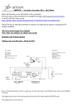
Signaling System 7 (SS7) defines the four-layer protocol of CCS7. Figure 1-1
shows the four-layer protocol of CCS7. Table 1-1 contains a description of the
functions that occur at each protocol layer.
For more information, refer to the Translations Guide.
DMS-100 Family CCS7 Maintenance Guide Volume 1 of 2 2000Q2
1-4 Maintenance summary
Figure 1-1 CCS7 model
CCS7
layers
4
Network application processes
Transaction capabilities
application part
ISDN user part
Presentation
Session
Transport
Signaling connection
control part
3
2
1
Network
Link
Physical
297-8991-545 Standard 06.01 July 2000
Message
transfer part
Maintenance summary 1-5
Table 1-1 Functions of CCS7 protocol layers (Sheet 1 of 2)
Layer
Function
Message
transfer part
(MTP)
Serves as a transport system for the transfer of signaling
messages between the nodes in a network. This level includes
the following three levels:
•
Level 1
— implements channelization and framing on the link
•
Level 2
— controls point-to-point connectivity
— performs error detection and correction,
synchronization, and flow control
— assembles bits into signaling units
•
Level 3
— with signaling connection control part (SCCP), controls
end-to-end connectivity
— notifies other nodes of faults and their effects
— reconfigures routing around faults
— performs logical address routing
SCCP
Provides additional functions to accommodate two types of
services: without connection and connection-oriented.
Performs the following functions:
•
Management control
— updates routing and translations based on traffic
congestion, failure, and recovery at the point code or
subsystem number level
— keeps track of application status and informs the user
when an application is not available
•
Message handler
— transfers signaling data units
— initiates global title translation (GTT)
— routes messages through the network and within the
node, based on the subsystem number
— checks the status of the destination, and routes
messages to MTP routing, ISUP routing, or subsystem
number routing
DMS-100 Family CCS7 Maintenance Guide Volume 1 of 2 2000Q2
1-6 Maintenance summary
Table 1-1 Functions of CCS7 protocol layers (Sheet 2 of 2)
Layer
Function
TCAP
Provides a set of generic procedures for applications based on
transactions. Controls the not circuit-related information
transfer between two or more nodes in a network.
ISUP
Provides the signaling that sets up, monitors, and takes CCS7
calls down on ISUP trunks. Supplies trunk-signaling capabilities
that allow network-wide feature transparency for CCS7
applications like integrated services digital network (ISDN).
CCS7 signaling messages
CCS7 is a packet-switched network based on the exchange of information
packets called signal units. The MTP level of the network is responsible for
reliable transport and delivery of signaling information across the CCS7
network. Each switch (also called a node) can format and transmit signal units
to other nodes in the network.
In a CCS7 network, the system sends signaling information with the following
three types of signal units:
•
link status signal units (LSSU), which report SL changes of state and have
priority over other unit types
•
message signal units (MSU), which transfer user information from one
node to another and are buffered until the MSU receives positive
acknowledgement
•
fill-in signal units (FISU), which fill the gaps between messages and are
sent when the transmit buffer is empty
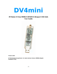
Figure 1-2 shows the basic signal unit format. Table 1-2 describes each field of
a signal unit.
297-8991-545 Standard 06.01 July 2000
Maintenance summary 1-7
Figure 1-2 Basic signal unit format
MSU
8
16
Flag
Check
LSSU
8
SIF
SIO
8
16
8
Flag
Check
Status
field
FISU
2 6
8
16
Flag
Check
1 7
LI
2 6
FSN
1 7
FSN
LI
2
6
1 7
LI
FSN
FIB
BIB
BSN
1 7
BSN
1 7
BSN
8
Bits
Flag
8
Bits
Flag
8
Bits
Flag
First bit
transmitted
Le ge nd :
BIB
BSN
FIB
FISU
FSN
1 7
Backward indicator bit
Backward sequence number
Forward indicator bit
Fill-in signal unit
Forward sequence number
LI
LSSU
MSU
SIF
SIO
Length indicator
Link status signal unit
Message signal unit
Signaling information field
Signaling information octet
Table 1-2 Fields of a signal unit (Sheet 1 of 2)
Field
Description
Backward indicator bit (BIB)
Part of the basic error control method, which
performs signal unit sequence control and
acknowledgement functions
Backward sequence number (BSN)
Sequence number of the signal unit that is
acknowledged
Check bits
Indicates16 bits for error detection
Flag
Indicates the start or end of a signal unit
DMS-100 Family CCS7 Maintenance Guide Volume 1 of 2 2000Q2
1-8 Maintenance summary
Table 1-2 Fields of a signal unit (Sheet 2 of 2)
Field
Description
Forward indicator bit (FIB)
Part of the basic error control method, which
performs signal-unit sequence control and
acknowledgement functions
Forward sequence number (FSN)
Indicates sequence number of the signal
unit
Length indicator (LI)
Indicates the number of octets to follow:
0 = FISU
1 or 2 = LSSU
greater than 2 = MSU
Signal information field (SIF)
Contains signaling information
Service information octet (SIO)
Contains the service indicator (SI):
0,1, or 2 = MTP
3 = SCCP
5 = ISUP
Contains the sub-service field (SSF), which
indicates if the message is for the national
or international network. This field also
indicates the message priority.
Present only in MSUs.
Status
Contains links status indications
TCAP messages
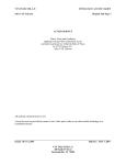
A TCAP message has two parts: the transaction part and the component part.
Figure 1-3 shows the format of a TCAP message. Table 1-3 describes the data
elements of a TCAP message.
Transaction part
The transaction part of a TCAP message associates the message with the
application process transaction. The application process transaction consists of
one or more messages exchanged between application processes at different
signaling points.
Component part
The component part of a TCAP message makes sure that units of information,
in the application process transaction, are formatted and exchanged correctly.
297-8991-545 Standard 06.01 July 2000
Maintenance summary 1-9
Figure 1-3 Format of a TCAP message
Package Total
type
TCAP
identifier message
length
Transaction Transaction Transaction
ID
identification ID length
(ID)
identifier
Transaction part
Component Component Component
sequence
sequence
length
ID
Component
Component part
DMS-100 Family CCS7 Maintenance Guide Volume 1 of 2 2000Q2
1-10 Maintenance summary
Table 1-3 Data elements of a TCAP message (Sheet 1 of 2)
Data element
Description
Package type
identifier
•
UNI: information flows in one direction only. Package type
identifier does not establish a transaction.
•
Query with permission: package type identifier initiates a
transaction; destination signaling point can terminate
transaction.
•
Query without permission: package type identifier initiates
a transaction; destination signaling point cannot terminate
transaction.
•
Conversation with permission: package type identifier
continues current transaction; destination signaling point
can terminate transaction.
•
Conversation without permission: package type identifier
continues a current transaction; destination signaling point
cannot terminate transaction.
•
Response: package type identifier indicates normal
termination of a transaction.
•
Abort: package type identifier indicates abnormal
termination of a transaction.
Total TCAP
message length
Indicates the total length of the TCAP message.
Transaction
identification
(ID) identifier
Assigned to each transaction: the application process at the
originating and the responding signaling point assigns the
identifier to the transaction.
Transaction ID
length
Indicates the number of octets the transaction ID identifier uses
in the TCAP message.
297-8991-545 Standard 06.01 July 2000
Maintenance summary 1-11
Table 1-3 Data elements of a TCAP message (Sheet 2 of 2)
Data element
Description
Transaction ID
Application process assigns transaction ID at the originating
and the terminating signaling point. The transaction ID not
always present, depending on the package type identifier.
Packagetypeidentifier Originating ID Responding ID
UNI
No
No
Query with permission
Yes
Yes
Query without permission
Yes
No
No
Yes
Conversation with permission
Conversation without permission Yes
Yes
Response
Yes
Yes
Abort
No
Yes
Component
sequence
identifier
Indicates the sequence of a message in a string of messages
associated with a transaction.
Component
sequence
length
Indicates the length of the component sequence identifier field
Component
Provides message encoding and decoding functions. Each
message contains one or more of the following types of
components:
•
Invoke: invokes an application-specific operation at a
remote node
•
Return result: returns the results of a successful operation
•
Return error: reports an operation that has failed
•
Reject: reports TCAP protocol violation, including
message-format errors and TCAP errors in procedure
ISUP messages
ISUP signaling sets up, monitors, and takes down CCS7 calls on ISUP
signaling trunks. ISUP allows the following enhanced trunk call processing
capabilities:
•
faster call setup
•
shorter holding times for call attempts that are not successful
•
ability to carry voice and data at the same time
DMS-100 Family CCS7 Maintenance Guide Volume 1 of 2 2000Q2
1-12 Maintenance summary
Figure 1-4 shows where ISUP messages are in the MSU. Figure 1-5 shows the
format of an ISUP message.Table 1-4 describes the parts of an ISUP message.
Figure 1-4 ISUP messages in message signal unit
MSU
8
16
8
Flag
Check
Optional
part
2 6
LI
SIF
SIO
ISUP message
Routing
label
Mandatory
variable part
Mandatory
fixed part
1 7
FSN
Message
type
1 7
BSN
8
Flag
Circuit
CIC
identification
code
Le ge nd :
BSN
FSN
ISUP
Backward sequence number
Forward sequence number
ISDN user part
297-8991-545 Standard 06.01 July 2000
LI
MSU
SIF
SIO
Length indicator
Message signal unit
Signaling information field
Signaling information octet
Bits
Maintenance summary 1-13
Figure 1-5 Format of an ISUP message
Floating
label
Circuit
Message Mandatory
ID code type code parameters
A to F
Mandatory fixed part
Pointers to
parameters
M to P
Pointer
to
optional
part
Length
indicator
of
parameter
M
Length
Parameter
indicator
P
of
parameter
P
Parameter
M
Mandatory variable part
Parameter
name
=X
Length
Parameter
indicator
M
of
parameter
X
End of
optional
parameters
Optional part
Table 1-4 Parts of an ISUP message (Sheet 1 of 2)
Part
Description
Routing label
Contains destination point code (DPC), origination point code
(OPC), and signaling link selector (SLS). For each circuit
connection, the routing label must remain constant for each
message that the system transmits in the same direction.
Circuit
identification
code (CIC)
Uniquely identifies each message with an appropriate ISUP
trunk, to a specified routeset.
Message type
Indicates the function and format of the ISUP message.
DMS-100 Family CCS7 Maintenance Guide Volume 1 of 2 2000Q2
1-14 Maintenance summary
Table 1-4 Parts of an ISUP message (Sheet 2 of 2)
Part
Description
Required fixed
part
Contains required parameters of fixed length. The message
type determines the order and length of parameters.
Required
variable part
Contains required parameters of variable length. The length
must be defined. A pointer indicates the number of octets
between the part and the first octet of the associated
parameter.
Optional part
Contains fixed or variable parameters. The optional part must
include the name and the length of the parameters.
CCS7 hardware architecture
A CCS7 network consists of switching and processing devices that signaling
links interconnect. The following sections provide a short description of the
nodes and signaling links:
•
Nodes
•
Signaling links
•
Routes, linksets, and routesets
•
Mapping CCS7 hardware to protocol
For more information, refer to the Provisioning Manual, PLN-8991-104 and
to the Translations Guide.
Nodes
CCS7 networks include the switches (nodes) that appear in Figure 1-6. Table
1-5 describes each node.
297-8991-545 Standard 06.01 July 2000
Maintenance summary 1-15
Figure 1-6 CCS7 nodes
STP
STP
SCP
Database
SSP
STP
STP
SCP
Database
STP pair A
STP pair B
SP
Table 1-5 Node functions
Node
Description
Signaling point
(SP)
Supports voice trunk capability
Service
switching point
(SSP)
Provides SP and SSP functions and communication
capabilities (for example, with CCS7 databases and toll calls)
Signaling
transfer point
(STP)
Transports messages between CCS7 nodes
Integrated node
(INode)
Combines the functions of an STP and an SSP
Signaling links
An SL consists of signaling terminal equipment and a transmission facility.
SLs exchange information between CCS7 nodes. Figure 1-7 shows CCS7 SLs.
Table 1-6 describes the link types.
DMS-100 Family CCS7 Maintenance Guide Volume 1 of 2 2000Q2
1-16 Maintenance summary
Figure 1-7 CCS7 signaling links
STP
STP
B-link
A-link
SCP
A-link
C-links
B-link
STP
F-link
Database
C-links
SSP
B-link
B-link
A-link
STP
A-link
A-link
A-link
SCP
B-link quad
SP
Database
E-link
Table 1-6 CCS7 links
Type
Function
A-links
Connect SPs, SSPs, and SCPs to STPs
B-links
Connect mated STPs in a SL quad
C-links
Connect two STP nodes to create an STP pair
D-links
Connect secondary STP pairs to primary STP pairs (not shown
in figure 1-7)
E-links
Connect SPs, SSPs, and SCPs to remote STP pairs
F-links
Connect SPs, SSPs, and SCPs to each other
Routes, linksets, and routesets
A signaling message can follow different routes between nodes. If one route
fails, the signaling message can use another route. A routeset is the group of
routes that a signaling message can take.
Each route uses a linkset to carry signaling messages. A linkset is a collection
of links. Each link has a direct connection between two nodes in the network.
297-8991-545 Standard 06.01 July 2000
Maintenance summary 1-17
One link can handle all signaling traffic for a routeset. Links can operate in a
load-sharing configuration.
A combined linkset consists of two linksets which provide equal but alternate
routing between the same nodes.
Figure 1-9 shows an example of a routeset and its associated linkset.
Figure 1-8 Example of a routeset and associated linkset
ISUP trunks
Linkset AB1
SSP A
SSP B
Associated mode
Linkset AD1
Linkset AC1
STP C
Quasi-associated
mode (through STP)
Quasi-associated
mode (through STP)
STP D
Note:
1. Routeset AB: Route 0 = linkset AB1
Route 1 = linkset AC1
Route 2 = linkset AD1
2. Associated (direct) mode has the highest priority.
3. Combined linkset: linkset AC1 and linkset AD1
Mapping CCS7 hardware to protocol
Figure 1-9 shows the functions of DMS components.
DMS-100 Family CCS7 Maintenance Guide Volume 1 of 2 2000Q2
1-18 Maintenance summary
Figure 1-9 Functions of DMS components
Cross-connect
device
MTP 1
MTP 2
LPP
MTP 3
• Message discrimination
(by point code)
• Message distribution to MTP
routing, to SCCP routing, to
ISUP distributor, or to MTP
network management
(network management
shared)
PB
ST
IPF
SCCP
All real-time
intensive call
setup features
Digital
trunk controller
ISUP
ISUP
distribution
to DTC
Network
SCCP
• SCCP router
• SCCP message
handler
Network module 0
Network module 1
DMS-bus
DMS-core
MTP
• Link maintenance
(shared with IPF)
• Network management for
traffic, links, and routes
(shared with IPF)
• Linkset control
Le ge nd :
IPF
PB
ST
TCAP
All
SCCP
• Linkset control
• SCCP management
control
• Database of point
orders and
subsystem
numbers
ISUP
• Translations
• Network
connection
setup
Integrated processor and F-bus interface
Paddle board
Signaling terminal
DMS architecture
A DMS-STP is a packet-switching system that transports messages between
CCS7 nodes. DMS-STPs are nodes that transfer messages between incoming
297-8991-545 Standard 06.01 July 2000
Maintenance summary 1-19
and outgoing SLs. The DMS-STPs do not originate or terminate messages,
except NWM information messages.
DMS-STPs are deployed in pairs. If one DMS-STP fails, the mate takes over
to make sure there is no interruption in service.
The DMS-STP combines the DMS-100 Family and DMS SuperNode
equipment. Figure 1-10 shows the DMS-STP equipment configuration.
Figure 1-10 DMS-STP equipment configuration
Magnetic
tape drive
Network 00
Alarm
crossconnect
shelf
Filler panel
Maint.
trunk
module
FSP
FSP
Input/
output
controller
Network 01
Office
alarm
unit
Input/
output
controller
Filler panel
Speech
link
connecting
panels
FSP
Disk drive
unit
IOE
FSP
MS 0
TME
LMS 0
LMS 1
DMS-bus
Link interface
shelf 1
MS 1
CPU0
CPU1
Link interface
shelf 2
DMS-core
SLM0
DSNE
FSP
SLM1
DPCC
Link interface
shelf 3
LPP
Office alarm system
DMS-100
Family equipment
DMS SuperNode
equipment
A DMS SP/SSP is a switching office that supports CCS7 voice trunk capability
(ISUP messaging). An SP provides an interface between subscriber lines and
the CCS7 network. An SSP supports TCAP messaging, which allows the SSP
to request information from CCS7 databases, like 800 Service.
The DMS SP/SSP combines the DMS-100 Family and DMS SuperNode
equipment. Figure 1-11 shows the DMS SP/SSP configuration.
DMS-100 Family CCS7 Maintenance Guide Volume 1 of 2 2000Q2
1-20 Maintenance summary
Figure 1-11 DMS SP/SSP configuration
Shelf 1
DTC
Shelf 2
FSP
DTC 00
DTC
DTC 01
DTE
Alarm
crossconnect
Network
00
MTM
Filler
panel
FSP
Office
alarm
unit
Speech
link conn.
panels
TME
Magnetic
tape
drive
FSP
FSP
FSP
MS0
LIM 0/1
FLIS 00
MS1
LIS 1
FLIS 01
FSP
Network
01
FSP
I/O
controller
Filler
panel
I/O
controller
CPU0 CPU1
DMS -- core
LIS 2
Filler panel
DDU
SLM0 SLM1
LIS 3
Filler panel
DSNE
IOE
DMS -bus
DPCC
LPP
EMC
Integrated node
An INode is a combined SSP and STP and it supports all the functions of an
SSP and an STP. The combination allows the use of a single site and a reduced
number of frames and cabinets. By integrating CCS7 elements into a single
node, operating companies can accrue cost savings that result from shared
equipment, reduced transmission facilities, and integrated operations,
administration, and maintenance.
DMS tasks
The following subsections describe DMS-STP, -SP/SSP, and INode tasks.
Gateway screening
Gateway screening controls access to a CCS7 network and database by other
CCS7 networks. The system screens CCS7 messages as the messages enter a
DMS-STP node. The screening process makes sure that only authorized
297-8991-545 Standard 06.01 July 2000
Maintenance summary 1-21
network users access facilities and services. The screening process is as
follows:
•
CCS7 messages contain routing data. This data includes destination and
originating point codes, GTT numbers, and information that identifies the
service that the message accesses.
•
Operating companies can specify the services of its network which users
can access. To specify the services, operating companies set screening
standards in the MTP and SCCP protocol layers.
•
Gateway screening denies network access to traffic that originates from
non authorized sources. Gateway screening denies access to traffic that
attempts to use services that are not leased.
Global title translation
GTT translates an application-specific address, such as a dialed 800 number,
into the CCS7 network address required to complete the call.
The CCS7 link interface unit (LIU7), the high-speed link router (HSLR), or the
multiple link interface unit (MLIU) performs GTT. GTT does not impose a
processing load on the computing module (CM). Each LIU7, MLIU, or HSLR
processor can handle GTT on all messages received on a SL. As a result, the
system can apply GTT with minimal impact on DMS-STP cross-delay.
Automated system maintenance
System software automatically initiates the following automated system
maintenance functions:
Trunk audits
When trunk audits detect a mismatch, the log system reports it. Maintenance
personnel realign associated data or trunk state information.
Circuit query audits
Every 24 h, the system software uses circuit-query messages to perform an
audit on the trunk states. The circuit-query messages check to see if the remote
state is compatible with the local state.
The system software can query up to 32 circuits at one time. The audit begins
at 2:00 a.m., unless you change the start time. To change the audit time, refer
to instructions for the CIRCUIT_QUERY_AUDIT_START_TIME parameter.
You must datafill table TRKSGRP in order for the system to perform this audit.
For more information, refer to the Translations Guide.
Recovery from failures
After restarts caused by the central control (CC) failures, system software
automatically initializes trunk data again. If the failure affects memory, the
DMS-100 Family CCS7 Maintenance Guide Volume 1 of 2 2000Q2
1-22 Maintenance summary
switch uses a reset circuit procedure to realign near- and far-end trunk state
information.
Note: For warm restarts, automatic maintenance does not occur. Call
processing continues. New call originations are lost.
Automatic maintenance features also handle DMS internal failures, such as
digital trunk controllers (DTC) and carrier outages.
ISUP trunk continuity tests
The signaling component and the voice component follows separate paths in a
CCS7 network. Successful transmission of the signaling component does not
automatically guarantee voice connections. Automatic continuity tests can be
specified for trunks through datafill. For more information, refer to the chapter
"Trouble isolation and correction methods"in this document.
Static data audits
Static data audits make sure there are no data differences between tables. The
CM contains master copies of the tables. To relieve the load on the CM, link
interface units (LIU) and DTCs also store the information.
The distributed data manager (DDM) first changes tables in the CM. After that,
the DDM updates the changes in the LIUs and DTCs. If the system loses or
discards a DDM message, data differences can occur .
The DDM checks the sequence of the numbers every 2 min and the table
consistency every hour. If the DDM detects a data differences, the DDM
updates the table in the LIU or DTC. This action makes the table same as the
table in the CM.
Table 1-7 lists the tables that are subject to static data audits.
Table 1-7 Table subject to static data audits
Table
DTC
LIU
C7NETWRK
Yes
Yes
C7LKSET
Yes
Yes
C7LINK
Yes
Yes
C7RTESET
Yes
Yes
C7TIMER
No
Yes
C7TRKMEM
No
Yes
C7ALIAS
No
Yes
297-8991-545 Standard 06.01 July 2000
Maintenance summary 1-23
Channelized link access
Channelized link access removes the need for external channel banks for DS-0
connections between signaling data links and LIU7s. Instead of requiring a
dedicated link to each LIU7, a channel bus (C-bus) performs access.
Duplicated network interface units (NIU) transfer data between the network
and the C-bus. MLIU channelized link access functions in the same way.
With channelized access, data transfer between signaling data links and LIU7s
or MLIUs integrates into automated system maintenance. Refer to the section
"Automated system maintenance" in this chapter for more information.
The following sections describe how channelized access works. For hardware
information, refer to the Provision Guide, PLN-8991-104.
•
Data transfer from LIU7s or MLIUs to the network
•
Bus configuration
•
LIU7 support of channelized access
•
C-bus
•
NIU
Data transfer from LIU7s or MLIUs to the network
The LIU7s and MLIUs transfer data on the C-bus. The NIU converts C-bus
data into DS30 format and transfers it to the network using one to four DS30
links. Figure 1-12 shows a channelized access external interface configuration.
Figure 1-13 shows a CCS7 channelized access system summary.
DMS-100 Family CCS7 Maintenance Guide Volume 1 of 2 2000Q2
1-24 Maintenance summary
Figure 1-12 Channelized access external interface configuration
Outside world
PCM
DTC
Network plane 0
Network plane 1
LIU7
CBI
LIU7
CBI
NIU
unit 0
CBC
C-bus 0
C-bus 1
297-8991-545 Standard 06.01 July 2000
NIU
unit 1
CBC
LIU7
CBI
LIU7
CBI
Maintenance summary 1-25
Figure 1-13 CCS7 channelized access system summary
DMS-core
SLM
DMS-bus
IOC
LIM
unit 0
Network
LIM
unit1
LPP
LIU7
NIU
LIU7
PDTC
TM (OAU)
unit 0 unit 1
CCS7 links
Bus configuration
The NIUs and LIU7s or MLIUs share the frame transport bus (F-bus) and the
C-bus on each link interface shelf (LIS).
The system duplicates F-buses for reliability. An F-bus is on all shelves in an
link peripheral processor (LPP). The LIU7s or MLIUs use the F-bus for data
and maintenance messaging. The NIUs use the F-bus for maintenance
messaging only.
The system duplicates C-buses for reliability. One C-bus is active and the other
is inactive. Each LIS in an LPP has a C-bus. LIU7s or MLIUs and NIUs use
the C-bus for data messaging only.
Figure 1-14 shows the bus configuration in the LPP.
DMS-100 Family CCS7 Maintenance Guide Volume 1 of 2 2000Q2
1-26 Maintenance summary
Figure 1-14 Bus configuration in the LPP
LIM unit 0
LIM unit1
F-bus 0
F-bus 1
LIU7
LIU7
NIU
unit 0
NIU
unit 1
LIU7
LIU7
C-bus 0
C-bus 1
LIU7 support of channelized access
The LIU7s associated with channelized access have the C-bus interface (CBI)
card. The LIU7 does not have the DS-0A or V.35 card used in LIU7s that are
not channelized.
MLIUs associated with channelized access have the CBI card, which gives
access to the C-bus for up to four signaling data links.
Figure 1-15 shows channelized LIU7 components and the actions between
these components.
297-8991-545 Standard 06.01 July 2000
Maintenance summary 1-27
Figure 1-15 Channelized LIU7 components and their interactions
F-bus 0
To other LIU7s
F-bus 1
C-bus 0
To
channel bus
controller
C-bus 1
LIU7
Channelized
bus interface
card
P-bus
to F-bus
interface
P-bus
Signaling
terminal
The CBI card performs the following functions when it receives data:
•
selects the correct C-bus data stream according to NIU activity
•
selects the channel from the active C-bus
•
transfers data serially to the signaling terminal (ST).
The CBI card performs the following functions when it transmits data:
•
drives the correct channels on both C-buses
•
provides C-bus fault detection, isolation functions, and loopbacks
The ST starts CBI maintenance diagnostics. A request from the processor bus
(P-bus) to F-bus interface starts all centrally requested ST diagnostics.
C-bus
The C-bus communicates with LIU7s or MLIUs and the network by the NIU.
The C-bus is a duplicated time-division multiplexed bus. The C-bus operates
at 4.096 MHz with 512 channels of 10 bits for each channel. Two duplicated
C-buses are present for each LIS in an LPP.
DMS-100 Family CCS7 Maintenance Guide Volume 1 of 2 2000Q2
1-28 Maintenance summary
The C-bus maintenance monitors for the following faults:
•
parity failures on channels allocated to C-bus ports
•
parity failures on channels not allocated to C-bus ports
When a C-bus does not have critical faults, C-bus maintenance notifies node
maintenance. Node maintenance returns the C-bus to service.
Because the NIU controls channel allocation, two LIUs never attempt to
transmit on the same C-bus channel.
Network interface unit
The NIU transfers data between the network and the C-bus. The NIU acts as a
switch. The NIU provides a maximum of 10 connection paths between the 512
channels available on the C-bus and the 120 channels available on DS30 links
from the network.
An NIU contains two NIU units. Each NIU unit contains the following
components:
•
integrated processor and F-bus interface (IPF), which contains 8 Mbytes of
memory for the local software load
•
channel bus controller (CBC), which contains integrated circuits to
monitor and control transmission of data through the NIU
•
link interface paddle board (LPB), which interfaces with a maximum of
four DS30 datalinks from the network to transmit data to and receive data
from the CBC
Figure 1-16 shows the NIU components and the actions that occur between the
components.
297-8991-545 Standard 06.01 July 2000
Maintenance summary 1-29
Figure 1-16 NIU components
F-bus 0
F-bus 1
C-bus 0
C-bus 1
NIU
unit 0
IPF
NIU
unit 1
P-bus
Channel
bus
controller
IPF
DS30
card
P-bus
Channel
bus
controller
DS30
card
Inter-CBC cable
Network plane 0
Network plane 1
The system duplicates NIUs for reliability. Each NIU transmits and receives a
data stream identical to the data stream that the mate NIU receives. The NIU
unit 0 controls C-bus 0, and NIU unit 1 controls C-bus 1. A cable between the
CBC in each NIU provides access to the other network plane. The cable also
provides a link for coordination and control signals for SWACTs.
The F-bus provides CM-to-NIU communication. The system resets NIU and
loads operational software. The NIU receives all maintenance messages
through the F-bus.
Diagnostics detect hardware problems before diagnostics put the units in the
in-service state. Diagnostics respond to problems detected while the NIU
carries traffic. When parity errors occur, the NIU switches to the other plane.
When the connection-specific integrity values in the data stream are not
correct, the NIU switches to the other plane.
DMS-100 Family CCS7 Maintenance Guide Volume 1 of 2 2000Q2
1-30 Maintenance summary
DMS documentation
Table 1-8 contains a list of CCS7 documentation. For more information on the
CCS7 documentation, refer to the Product Documentation Directory,
297-8991-001.
Table 1-8 CCS7 documentation (Sheet 1 of 2)
Document
Title
Abstract
297-8121-020
DMS SuperNode
Signaling Transfer Point
Service Guide
This document contains reference
information for the Signaling
Engineering, And Administration
System (SEAS). Information
includes the effect of SEAS
commands on the DMS-STP
switch, and a summary of interface
messages that report DMS-STP
events to SEAS.
297-xxxx-350
Translations Guide
This document describes the
translations datafill and data
schema tables. This document is
designed for use by the
administration personnel.
297-xxxx-543
Alarm andPerformance
Monitoring Procedures
This document contains alarm and
performance monitoring
maintenance procedures. The
procedures described in this
document are for maintenance
personnel in an operating
company.
297-xxxx-544
Trouble Locating and
Clearing Procedures
This document contains trouble
locating and clearing maintenance
procedures. The procedures
described in this document are for
maintenance personnel in an
operating company.
297-xxxx-545
Recovery Procedures
This document contains recovery
procedures. The procedures
described in this document are for
maintenance personnel in an
operating company.
Note: The xxxx in the document number represents the product
computing-module load (PCL).
297-8991-545 Standard 06.01 July 2000
Maintenance summary 1-31
Table 1-8 CCS7 documentation (Sheet 2 of 2)
Document
Title
Abstract
297-xxxx-546
Routine Maintenance
Procedures
This document contains routine
maintenance procedures. The
procedures described in this
document are for maintenance
personnel in an operating
company.
297-xxxx-547
Card Replacement
Procedures
This document contains card
replacement procedures. The
procedures described in this
document are for maintenance
personnel in an operating
company.
PLN-8991-104
Provisioning Manual
This document describes how the
DMS SP/SSP operates and the
hardware and software required to
operate the DMS-SP/SSP.
Note: The xxxx in the document number represents the product
computing-module load (PCL).
DMS-100 Family CCS7 Maintenance Guide Volume 1 of 2 2000Q2
2-1
2 CCS7 network logs
This chapter contains background information on logs, the log groups and logs
associated with a CCS7 network and references indicating for additional
information.
Logs
Logs are messages generated by the DMS switch when a significant event
occurs. Logs include status and activity reports, reports on hardware or
software faults, test results, changes in state, and other events or conditions
likely to affect the performance of the switch.
Log types
There are over 1600 types of logs, arranged in approximately 140 groups.
Messages in the following log groups must be monitored:
•
AUD—Audit logs report the integrity of central control (CC) software, and
any attempts to correct errors.
•
AUDT—Audit logs report the integrity of peripheral module (PM)
software, and any attempts to correct errors.
•
CCS—Common channel signaling logs report on CCS7 linkset and
routeset management functions, such as maintaining signaling linksets,
restoring signaling to a link in the event of links failure.
•
C7UP—CCS7 ISDN user part (ISUP) subsystem logs control circuit group
blocking and circuit group unblocking messages as part of ISUP trunk
maintenance.
•
C7TU—CCS7 test utility logs display CCS7 link messages that are traced.
•
DDM—Distributed data manager (DDM) logs monitor simultaneous
updates of data to many DMS nodes.
•
IDPL—IDPL logs report the detection and correction of identifiers that are
in use or reserved.
•
OMAP—Operational Measurement Application Part (OMAP) logs
document the results of message routing verification tests (MRVT).
DMS-100 Family CCS7 Maintenance Guide Volume 1 of 2 2000Q2
2-2 CCS7 network logs
•
PM—PM logs monitor all hardware and software systems that provide
interfaces with external line, trunk, or service facilities.
•
TCAP—Transaction capabilities application part (TCAP) logs provide a
common protocol for remote operations across the CCS7 network.
Log output
Log output is controlled as follows:
•
Log output is customized by changing the customer data tables listed in the
Translations Guide.
•
Commands are entered in the LOGUTIL level of the MAP that temporarily
override parameters set in the customer data tables.
LOGUTIL
The LOGUTIL level of the MAP contains commands that allow you to browse
software buffers for information about messages, and to temporarily control
the routing and generation of reports.
The following documents contain additional information on the operation and
features of LOGUTIL:
•
Log Report Reference Manual
•
DMS-100 Family Maintenace and Operations Manual, 297-8991-500
CCS7 network logs
Table 2-1 lists logs that are associated with a CCS7 network.
Table 2-1 Summary of CCS7 network logs (Sheet 1 of 14)
Log
Definition
AUD logs
AUD577
A call traps or dies and a regular HDB is an extension linked to the call.
AUD578
A call traps or dies and a large HDB is an extension block linked to the call.
AUD579
A call traps or dies and an extra-large HDB is an extension block linked to the call.
AUDT logs
AUDT608
An audit discovers a mismatch in the 8-bit signaling link selection (SLS) states
between the computing module (CM) and a link interface unit (LIU).
AUDT609
An audit reports an invalid 8-bit SLS activation state.
AUDT612
A CCS audit discovers a mismatch in the link availability states between the
computing module and a peripheral module.
297-8991-545 Standard 06.01 July 2000
CCS7 network logs 2-3
Table 2-1 Summary of CCS7 network logs (Sheet 2 of 14)
Log
Definition
AUDT613
An audit discovers a mismatch in the linkset availability states between the computing
module and a peripheral module.
AUDT614
A CCS audit discovers a mismatch in the routeset availability states between the
computing module and a peripheral module.
AUDT615
A CCS audit discovers a mismatch in the route availability states between the
computing module and a peripheral module.
AUDT616
An audit discovers a mismatch in the link synchronization (Sync) states between the
computing module and the signaling terminal (ST).
AUDT617
An audit reports CM linkset SLS data error detection and data mismatches between
the CM and LIU linkset SLS data.
AUDT618
An audit reports CM combined linkset SLS data error detection and correction and
data mismatches between the CM and LIU combined linkset SLS data.
AUDT620
An audit discovers a mismatch in the link discard levels between the computing
module and the signaling terminal (ST).
AUDT622
A CCS audit discovers a mismatch between the link discard levels of the computing
module and a peripheral module.
AUDT623
A CCS audit discovers a mismatch in routeset congestion levels between the
computing module and a peripheral module.
AUDT624
The audit software detects that a link has remained in the local processor outage
(LPO), faulty link (FtLk), or initializing (Init) state for at lease one audit cycle. The link
state is displayed as it was before the audit. The audit recovers the link.
AUDT626
A signaling connection control part (SCCP) audit detects an integrity mismatch
between the computing module static data and the MSB7 or LIU static data.
AUDT628
The audit software detects a data mismatch between the computing module and the
periperal module data for tables C7NETSSN, C7GTTYPE, and C7GTT.
CCS logs
CCS101
A CCS link has failed with the reason shown in the log report. The link state displayed
is as it existed prior to the link failure.
CCS102
A CCS link has reached the sync or aligned (Alnd) state, and is ready to carry traffic.
A link in the aligned state must be returned to service from manual busy (ManB) in
order to carry traffic.
CCS103
A CCS link has been attempting to align, and has failed to achieve synchronization
within a specified time.
DMS-100 Family CCS7 Maintenance Guide Volume 1 of 2 2000Q2
2-4 CCS7 network logs
Table 2-1 Summary of CCS7 network logs (Sheet 3 of 14)
Log
Definition
CCS104
The far end of a CCS link has a processor outage. The remote processor outage
(RPO) can also occur when a CCS link is manually busied or inhibited at the far end.
The link maintains synchronization, and when the far end has recovered, is ready for
traffic.
CCS105
A CCS link has recovered from a remote processor outage (RPO).
CCS106
A CCS link has been manually deactivated.
CCS107
A CCS7 link test has failed on the specified link.
CCS109
A CCS7 link has reached sync state but could not nail up (reserve) the link. As a
result, the next computing module restart will cause the link alignment to be lost.
CCS120
The CCS subsystem generates log report CCS120 hourly to provide detailed
performance information on any CCS7 link that has exceeded threshold values, as
determined by the operational measurements associated with this log.
CCS121
A link, already perceived by MTP level 3 as unavailable to SS7 user-part message
traffic, has undergone a minor state change. The state change may be due to
inhibiting or uninhibiting at MTP level 3, or failure, restoration, or activation of the link
at MTP level 2. The link remains unavailable if one or more link outage conditions
persists.
CCS124
A key high-speed-link performance parameter crosses a predefined threshold value.
CCS125
A key high-speed-link performance parameter crosses a predefined threshold value.
CCS140
A user part unavailable (UPU) message has been received by the MTP layer in the
CM.
CCS141
The local user part status has changed.
CCS142
The UPU message has been directed, by the MTP, to an unavailable user part.
CCS146
The CCS7 subsystem generates log CCS146 when a message transfer part (MTP)
restart procedure is in progress.
CCS148
LIU auto imaging has been initiated.
CCS149
Log CCS149 is generated to indicate the following:
CCS151
•
auto-imaging is finished and succeeded
•
auto-imaging was unsuccessful due to an internal error
•
auto-imaging was unsuccessful due to an exceeded delta file threshold
•
auto-imaging is disabled
A CCS routeset has been placed offline.
297-8991-545 Standard 06.01 July 2000
CCS7 network logs 2-5
Table 2-1 Summary of CCS7 network logs (Sheet 4 of 14)
Log
Definition
CCS152
A CCS routeset has been manually busied.
CCS153
A routeset return to service (RTS) command has passed but not all parts of the
routeset are functioning enough to provide service.
CCS154
A CCS routeset is unavailable to deliver traffic to its destination, and all traffic to that
destination has been stopped.
CCS155
A CCS routeset is able to deliver traffic to its destination, and all traffic to that
destination has been restored.
CCS156
A CCS link has been placed offline.
CCS157
A CCS link has been manually busied.
CCS158
A CCS link is system busied after a request for return to service (RTS) fails.
CCS159
A CCS link has been locally inhibited.
CCS160
A CCS link has been remotely inhibited.
CCS161
Local inhibit on a CCS link has been removed.
CCS162
The remote inhibit on a CCS link has been removed.
CCS163
The CCS link becomes available for signaling traffic.
CCS164
The CCS link becomes unavailable for signaling traffic, and traffic has been removed
from the link.
CCS165
The switching office at the far end of the CCS7 link did not obey the CCS7 protocol.
CCS166
A CCS route has received the transfer allowed signal from the network. The route now
has an acceptable level of routing in the CCS network.
CCS167
A CCS route has received the transfer restricted signal from the network. The route
now has a restricted level of routing in the CCS network.
CCS168
A CCS route has received the transfer prohibited signal from the network. The route
now has no service for routing in the network.
CCS169
A CCS route has received an unexpected signal from the network. The signal is
logged and discarded.
CCS170
A CCS routeset has received an invalid level 3 message from the network.
CCS171
A CCS linkset has received an invalid level 3 message from the network.
CCS172
A transfer controlled signal has been received, and is the result of either a rise or drop
in the congestion level of a routeset.
DMS-100 Family CCS7 Maintenance Guide Volume 1 of 2 2000Q2
2-6 CCS7 network logs
Table 2-1 Summary of CCS7 network logs (Sheet 5 of 14)
Log
Definition
CCS173
The transmission buffer of a CCS link has become congested.
CCS174
Generated when CCS7 messages that originate in the central control/communication
module (CC/CM) core have invalid destination point codes.
CCS175
A CCS7 route set becomes restricted (when the normal route of the routeset becomes
unavailable). The route becomes unavailable when a transfer prohibited (TFP)
message is received for the route, or the route is not in service (linkset is system or
manual busy).
CCS176
The remote service module (RSM) link audit detects an inconsistency in link data.
CCS177
The remote service module (RSM) link audit detects an inconsistency in route data.
CCS178
Generated when offic parm CCS7_H0H1_RCP is changed.
CCS180
A member of a PPC routeset has changed its availability state to allowed for the
indicated route.
CCS181
A member of a PPC routeset has changed its availability state to restricted for the
indicated route.
CCS182
A member of a PPC routeset has changed its availability state to prohibited for the
indicated route.
CCS183
A member of a PPC routeset has changed its availability state to unavailable for the
indicated route.
CCS184
A member of a PPC routeset has changed its availability state to restricted for the
indicated route.
CCS185
A member of a PPC routeset has changed its availability state to allowed for the
indicated route.
CCS186
A single link event initiates one or more changes to the state of a routeset.
CCS188
This log indicates a signaling message handling (SMH) processor overload condition.
This log reports processor overload level changes.
CCS190
A bit error rate test (BERT) is manually stopped or queried from the C7BERT MAP
level, or when a BERT is automatically stopped by the SETSTOP command.
CCS198
Generated hourly, containing operational measurements (OM) counts of signaling
unit (SU) errors, negative acknowledgements, and automatic changeovers received
for specified links that have exceeded the threshold value in the previous hour.
CCS199
A CCS7 link fails during a computing module restart.
297-8991-545 Standard 06.01 July 2000
CCS7 network logs 2-7
Table 2-1 Summary of CCS7 network logs (Sheet 6 of 14)
Log
Definition
CCS201
A signaling connection control part (SCCP) message is received from the network
that is invalid and cannot be decoded.
CCS202
An SCCP message with an invalid called party address (CDPA) is received from the
network, and cannot be routed.
CCS203
An SCCP mesage is received from the network that has an invalid calling party
address (CGPA). An attempt to route the message is made.
CCS204
An SCCP message is received from the network that is destined for an unknown local
subsystem.
CCS205
An SCCP message is received from the network that requires global title translation
(GTT) but the message contains a translation type for which the node has no
translation tables.
CCS206
An invalid SCCP message is received from a local subsystem. The message is
discarded.
CCS207
An SCCP management message (SCMG) that has invalid data is received by the
local SCMG subsystem. The message is discarded.
CCS208
The status of a remote point code is changed to offline from the MAP terminal.
CCS209
The status of a remote point code is changed to manual busy from the MAP terminal.
CCS210
The status of a remote point code that has been returned to service changes to
system busy. This log indicates the number of subsystems at each remote point code
that changed state to system busy.
CCS211
The status of a remote point code changes to available.
CCS212
The status of a remote subsystem is changed to offline from the MAP terminal.
CCS213
The status of a remote subsystem is changed to manual busy from the MAP terminal.
CCS214
The status of a remote subsystem changes to initializing, and occurs when the
subsystem has been returned to service, but its routing status has not been obtained,
and a subsystem status test (SST) is in progress on that remote subsystem.
CCS215
The status of a remote subsystem changes to system busy. Occurs when the
subsystem has been returned to service, but its routing status becomes prohibited,
and an SST on the remote subsystem is in progress.
CCS216
A remote subsystem becomes available.
CCS217
The status of a local subsystem changes to offline.
CCS218
The status of a local subsystem changes to manual busy.
DMS-100 Family CCS7 Maintenance Guide Volume 1 of 2 2000Q2
2-8 CCS7 network logs
Table 2-1 Summary of CCS7 network logs (Sheet 7 of 14)
Log
Definition
CCS219
The status of a local subsystem changes to system busy.
CCS220
The status of a local subsystem changes to in service.
CCS221
An SCMG at a remote point code is performing a subsystem status test (SST) on a
local subsystem.
CCS222
An SCMG has received an SSP for a remote subsystem that is not datafilled in the
local node’s network routing tables.
CCS223
The SCMG management has received an SSA for a remote subsystem that is not
datafilled in the local node’s network routing tables.
CCS224
The SCMG has received an SST for the status of a local subsystem; however, the
calling party address is not sufficient to return a response.
CCS225
A remote point code has been removed from table C7NETSSN and is now
unequipped.
CCS226
A message with an invalid global title (GT) in the called party address (CDPA) has
been received from the network. Routing is attempted, even with the protocol error.
CCS227
A message with an invalid GT in the calling party address (CGPA) has been received
from the network. Routing is attempted, even with the protocol error.
CCS228
A message is received from the network requiring a global title translation (GTT). The
network address produced is invalid for an SCCP at an SSP, and the message is
returned.
CCS229
There is a status change for a remote point code that has been returned to service,
and is now in-service trouble. This situation occurs when the routeset to this point
code becomes congested or restricted.
CCS230
The SCCP management receives a message acknowledgement UDTS. The DMS
software is in error for requesting the return, or another node in the network is in error
for returning the message.
CCS231
The status of a local subsystem changes to in-service trouble. A local subsystem is
in-service trouble if less than the minimum number of instances specified in table
C7LOCSSN of the subsystem are in service or in-service trouble.
CCS232
The status of a local subsystem instance changes to offline from the MAP terminal.
CCS233
The status of a local subsystem instance changes to manual busy from the MAP
terminal.
CCS234
The status of a local subsystem instance changes to system busy.
CCS235
The status of a local subsystem instance changes to in service.
297-8991-545 Standard 06.01 July 2000
CCS7 network logs 2-9
Table 2-1 Summary of CCS7 network logs (Sheet 8 of 14)
Log
Definition
CCS236
The status of a local subsystem instance changes to in-service trouble. In this state,
the instance only receives messages pertaining to currently active transactions. No
new transactions will start at that instance.
CCS237
A request for removal from service by a local subsystem has been granted or denied
from a remote node. The granting of permission may or may not result in removal from
service of the local subsystem.
CCS238
An invalid co-ordinated state change control (CSCC) message is received from the
network.
CCS240
An invalid traffic mix information (TFMI) message is received from the network.
CCS241
The SCCP fails to route a message in a link interface unit (LIU). This log is subject to
thresholding. Each LIU routing failure generates a maximum of n logs in a 1-min
period. If more than n routing failures occur in a 1-min period, no additional CCS2241
logs are generated. Instead, a CCS243 log is generated at the end of the 1-min
period. Currently, n is set to 20.
CCS242
The local SCCP susystem attemps to format a global title (GT) in the called party
address of a message it is about to transmit, and, SCCP determines if the interanl
global title translation (GTT) name (GTTNAME) used by the subsystem is not
datafilled in the GTTID field in table C7GTTYPE.
CCS243
Excessive SCCP routing failures occur in the LIU peripheral module. Normal routing
failures are reported in CCS241 logs. However, when the number of routing failures
during a 1-min period exceeds a threshold (currently 20), CCS241 logs are no longer
generated to prevent overloading of the log system. Instead, routing failures are
counted and reported at 1-min intervals in CCS243 logs. The difference between the
routing failures value and the failures not logged value in CCS243 is the threshold
value (currently 20). A threshold quantity of CCS241 logs (currently 20) is always
generated before a CCS243 log is created.
CCS244
Table C7LOCSSN has not been datafilled for a local subsystem that is trying to define
its own network address which consists of point code and subsystem number.
CCS249
An extended unit data (XUDT) or an extended unit data service (XUDTS) message is
received from the CCS7 network that contains a bad optional parameter, an incorrect
or unknown optional parameter, or an incorrect optional parameter length.
CCS250
The local subsystem enters an alarm state with the Freephone Services alarm.
CCS251
An instance of a local subsystem (SSI) which uses Connection Oriented SCCP
experiences deload.
CCS252
A local subsystem that uses Connection Oriented SCCP has experienced deload as
a result of at least one of its instances experiencing deload. The rest of the subsystem
instances (SSI) are in the in-service (Insv) or in-service trouble (ISTB) state.
DMS-100 Family CCS7 Maintenance Guide Volume 1 of 2 2000Q2
2-10 CCS7 network logs
Table 2-1 Summary of CCS7 network logs (Sheet 9 of 14)
Log
Definition
CCS253
This message is generated if a timeout has occurred during the reassembly of a
XUDT message. The message being processed has more than 1024 bytes of data.
A message is being processed that requires segmentation but the subsystem has not
been enabled for segmentation and reassembly.
CCS254
The system generates log CCS254 when message routing fails in the computing
module (CM).
CCS402
Up to 14 ILLP paths have failed more than 10 times within a 1-min period.
CCS403
Up to 14 ILLP paths have recovered more than 10 times within a 1-min period.
CCS404
More than 24 ILLP paths have failed or recovered within a 1-min period.
CCS506
The gateway screening monitor option is activated for a particular gateway screening
function, and this function is the final function performed in the screening of a
message.
CCS601
This log is generated when an LIU is returned to service from a manual busy (ManB)
state and the delta file could not be used to data sync the LIU. If the delta file cannot
be used, the LIU takes longer to return to service, as tables C7GTT and C7GTTYPE
have to be fully downloaded from the CM.
CCS650
The system generates log report CCS650 when a signaling transfer point software
optionality control (STP SOC) audit finds too many tuples in a table.
CCS651
The system generates log report CCS651 when a signaling transfer point software
optionality control (STP SOC) audit detects active links with STP capability while the
STP SOC option is set to IDLE. When the STP SOC option is set to IDLE, an
integrated node (INode) office operates as a service switching point (SSP). Active
links in an SSP office operate without STP capability.
CCS652
The system generates log report CCS652 when a signaling transfer point software
optionality control (STP SOC) audit detects that 8-bit SLS is active while the STP
SOC option is set to ON. Eight-bit SLS is supported only when the STP SOC option
is set to IDLE.
CCS701
A static data audit has detected a problem with a table. The log displays the table, and
the system action taken.
CCS703
Log703 is generated when a distribute data manager (DDM) audit on the internal
c7_feature_activation_table has detected and corrected a mismatch between the
computer module (CM) and the LIU.
CCS730
A DDM audit has failed for a particular xlist block on a node. The specified xlist block
is in use by the routeset.
CCS731
A DDM audit has failed for a particular xlist block on a node. The specified xlist block
is in use by the route of the routeset.
297-8991-545 Standard 06.01 July 2000
CCS7 network logs 2-11
Table 2-1 Summary of CCS7 network logs (Sheet 10 of 14)
Log
Definition
CCS732
A summary log indicating the number of DDM audits that have failed in the last 2 min.
CCS733
A summary log indicating the CCS180 to CCS185 logs that have been suppressed in
the last 2 min.
CCS734
The xlist table has overflowed while attempting to add a member.
CCS735
Indicates that xlist management has been enabled or disabled on the node.
CCS791
A summary log generated every hour detailing the audit activity for the MTP/ISUP
tables.
C7TU logs
C7TU101
There is a match between the incoming link message from the LIU or the MSB7 and
the C7TU match table.
C7TU102
There is a match between the outgoing link message to the LIU or the MSB7 and the
C7TU match table.
C7TU103
A user created message has been placed into the LIU or MSB7 on the CCS7 link.
C7TU104
A user created message has been placed into the LIU or MSB7 to be sent out onto
the CCS7 link.
C7TU105
A user created message has been placed into the LIU or MSB7 but has not been sent
out onto the CCS7 link.
C7TU106
C7TU has received a message that can not be interpreted.
C7TU108
This is a response to a destination point code (DPC) command.
C7TU109
This is a response to the SELECT command when it is used to turn tracing on.
C7TU110
This is a response to the SELECT command when it is used to turn tracing off.
C7TU401
This log indicates that a periperal module is sending more than 10 log messages per
minute to the computing module. The number of messages not sent is indicated in the
log.
C7UP logs
C7UP100
No acknowledgement message is received from the far-end office.
C7UP101
An unreasonable message is received on a trunk.
C7UP102
A CCS7 connection is released due to an abnormal condition.
C7UP103
A blocked or unblocked circuit conditions.
DMS-100 Family CCS7 Maintenance Guide Volume 1 of 2 2000Q2
2-12 CCS7 network logs
Table 2-1 Summary of CCS7 network logs (Sheet 11 of 14)
Log
Definition
C7UP104
A circuit group blocking or unblocking conditions.
C7UP105
An unsuccessful ISDN call attempt occurs.
C7UP106
Problems occur because of resource shortages.
C7UP107
Generated after a continuity check test on the indicated outgoing trunk.
C7UP108
A response has not been received to either a facility request message or an
information request message after a specified period of time.
C7UP109
The state of an ISUP trunk is being changed to match the far end.
C7UP110
The far-end office does not use the same protocol standard message format.
C7UP111
An outgoing call attempt fails.
C7UP112
A call in progress has received an unexpected ISUP message type.
C7UP113
An ISUP trunk detects a maintenance problem.
C7UP114
ISUP does not receive a response from the far end to a release circuit (REL) or reset
circuit (RSC) message before a timeout occurs.
C7UP115
The ISUP message table has no space available to store group blocking or group
RSC messages.
C7UP116
The ISUP trunks are blocked due to an outage on digital trunk controller No. 7 (DTC7),
a DTC7 carrier, or an interperipheral message link (IPML).
C7UP117
The previously blocked ISUP trunk is unblocked due to the recovery of the DTC7, the
DTC7 carrier, or an IPML.
C7UP120
An invalid number has been received in the range field of a circuit group message.
For the ANSI ISUP protocol, an invalid number is zero or a number greater than 23.
For other types of networks, an invalid number is zero, or a number greater than 255.
C7UP121
A history data block (HDB) was not allocated due to under-provisioning. Also
indicates that sufficient data store cannot be allocated to update the number of buffers
available for maintenance messages.
C7UP123
A specified percentage of trunks are locked out due to a remote line controller (RLC)
timeout.
C7UP300
An ISUP trunk has timed out waiting for acknowledgement of the first RSC sent.
DDM logs
DDM100
The DDM has successfully transferred data to a PM.
297-8991-545 Standard 06.01 July 2000
CCS7 network logs 2-13
Table 2-1 Summary of CCS7 network logs (Sheet 12 of 14)
Log
Definition
DDM101
The DDM failed to download distributed data to a PM.
DDM102
The DDM failed to download an update to the distributed data to a PM.
DDM103
The DDM successfully completed the downloading of data to a node for a single table.
DDM104
The DDM cannot maintain data in a PM, and is caused by node failure, or when the
DDM is unable to download tables.
DDM105
Data was successfully downloaded to a PM.
DDM106
An audit of the distributed data failed.
DDM107
An attempt to retrieve operational measurement data failed.
DDM108
An error was detected on the link interface module (LIM). CCS7 data in the LIUs
connected to the LIM may be corrupted.
IDPL logs
IDPL300
An IDPL audit reports the detection and correction of identifiers that are reserved but
not used. The identifiers can be used.
IDPL800
Created when 80%, of the maximum number of specified identifiers, are in use.
IDPL801
Created when the maximum number of specified identifiers are in use.
IDPL810
A CCS7 server running applications that use identifier pools (IDPL) generates this log
on the computing module (CM) when 80% of transaction capabilities application part
(TCAP) identifiers, either transaction or component, are in use.
IDPL811
A CCS7 server running applications that use identifier pools (IDPL) generates this log
on the computing module (CM) when all transaction capabilities application part
(TCAP) identifiers, either transaction or component, are in use.
IDPL900
An IDPL audit reports the detection and correction of an identifier that is reserved but
not currectly in use. The identifier is corrected to be used again.
OMAP logs
OMAP100
Log OMAP100 generates when an operations maintenance application service
element (OMASE) decode error occurs. If OMASE or a transaction capability
application part (TCAP) cannot correctly decode the received message, this log is
generated.
OMAP110
Log OMAP110 generates when the operations maintenance application service
element (OMASE) user’s state changes.
DMS-100 Family CCS7 Maintenance Guide Volume 1 of 2 2000Q2
2-14 CCS7 network logs
Table 2-1 Summary of CCS7 network logs (Sheet 13 of 14)
Log
Definition
OMAP210
Log OMAP210 generates when the message transfer part (MTP) routing verification
test (MRVT) core process starts correctly. This log is generated from the originating
signaling transfer point (STP). The intermediate node and destination node do not
generate this log when they receive an MRVT message.
OMAP220
Log OMAP210 generates when an intermediate node or a test destination node
detects an error during a message transfer part (MTP) routing verification test
(MRVT).
OMAP230
Log OMAP230 generates at the initiating signaling point under the following
conditions:
OMAP240
•
when all expected MTP message routing verification acknowledgments (MRVA)
are received
•
when the MTP routing verification test (MRVT) T1 timer expires
Log OMAP240 generates each time a signaling point (SP) that detects an error sends
a message transfer part (MTP) routing verification result (MRVR) message to the test
initiating SP. Failed and successful trace results are reported by the destination SP
when a trace request is made by the originating signaling transfer point (STP).
PM logs
PM102
A PM status is changed to system busy by a system request.
PM103
A PM is placed offline from a manual-busy state, or when a PM is added to its
associated inventory table while offline and unequipped.
PM104
A PM state is changed from offline to unequipped, or when a tuple is deleted from
tables LTCRINV or LIUINV.
PM105
A PM state changes to manual-busy.
PM106
A PM returns to service.
PM128
A PM state changes to in-service trouble.
PM181
A maintenance action step has occurred in a PM.
PM182
A PM P-side link state changes to manual busy.
PM183
A PM P-side link state changes to system busy.
PM184
A PM P-side link returns to service.
TCAP logs
TCAP100
Created when a message is generated by certain faulty conditions.
297-8991-545 Standard 06.01 July 2000
CCS7 network logs 2-15
Table 2-1 Summary of CCS7 network logs (Sheet 14 of 14)
Log
Definition
TCAP101
Created when a message is generated by certain faulty conditions.
TCAP199
Miscellaneous error conditions.
Priority logs
Table 2-2 lists logs that should be monitored, their alarm class, and suggested
treatment.
Table 2-2 CCS7 network priority logs (Sheet 1 of 3)
Log
Alarm class
Action
CCS101
minor
A hardware or facility fault exists. Deactivate the link and replace the
faulty equipment.
CCS103
minor
Refer to the Alarm and Performance Monitoring Procedures to determine
the cause of the link alignment failure and synchronize it.
CCS109
no alarm
Link could not be nailed up. Keep a record of each occurrence.
CCS120
no alarm
CCS7 link has exceeded threshold values. Monitor the log and alert
support groups.
CCS121
no alarm
Check other CCS logs that indicate underlying link and linkset failures.
Look for a CCS101 or CCS158 link event log, which indicates the root
cause.
CCS157
minor
Link has been manually busied. Keep a record of each occurrence.
CCS158
minor
Refer to the Alarm and Performance Monitoring Procedures
for assistance in returning the link to service.
CCS159
minor
Link has been locally inhibited. Keep a record of each occurrence.
CCS160
minor
Link has been remotely inhibited. Keep a record of each occurrence.
CCS164
minor
Refer to the Alarm and Performance Monitoring Procedures
for assistance in returning the link to service.
CCS165
no alarm
Far-end office generated a CCS7 protocol violation. Set threshold.
CCS167
major
A CCS7 route has restricted level of network routing. Set threshold.
CCS168
major
A CCS7 route has no service for network routing. Keep a record of each
occurrence.
DMS-100 Family CCS7 Maintenance Guide Volume 1 of 2 2000Q2
2-16 CCS7 network logs
Table 2-2 CCS7 network priority logs (Sheet 2 of 3)
Log
Alarm class
Action
CCS169
no alarm
A CCS7 route has received an invalid network message. Set threshold to
monitor.
CCS170
no alarm
Verify CCS7 data to ensure that linksets and routesets are properly
defined at both the local and far-end office.
CCS171
no alarm
Verify CCS7 data to ensure that linksets and routesets are properly
defined at both the local and far end office.
CCS172
no alarm
Investigate reasons for congestion in the network.
CCS174
no alarm
CCS7 messages that originate in the central control/ communication
module (CC/CM) core have invalid destination point codes (DPC).
Monitor the log and inform next level of support.
CCS175
major
If the route has failed, try to recover the route. If a transfer prohibited
(TFP) message was received, the fault is in another network node.
CCS186
major
If this log occurs check other CCS logs and alarms which indicate
underlying link and linkset failures and correct. Look specifically for a
CCS010, CCS157 or CCS158 link event log which will indicate the root
cause.
Display the affected routeset at the C7LKSET MAP level. Review the
status of the member links and attempt to bring unavailable links to an
in-service (InSv) state.
Display the affected linkset at the C7LKSET MAP level. Execute
command “Query Usr” to display the routesets which use the linkset.
CCS201
no alarm
An invalid SCCP message has been received and discarded. Set
threshold to monitor.
CCS202
no alarm
SCCP message received with invalid called party address. Set threshold
to monitor originating mode.
CCS203
no alarm
SCCP message received with invalid calling party address. Set threshold
to monitor originating node.
CCS204
no alarm
SCCP message received with invalid subsystem destination. Set
threshold to monitor originating node.
CCS206
no alarm
Invalid SCCP message received from local subsystem. Set threshold to
monitor subsystem.
CCS207
no alarm
Invalid SCCP management message received by the local SCMG
subsystem. Set threshold to monitor originating node.
CCS224
no alarm
SCMG received and SST message with an invalid calling party address.
Set threshold to monitor originating node.
297-8991-545 Standard 06.01 July 2000
CCS7 network logs 2-17
Table 2-2 CCS7 network priority logs (Sheet 3 of 3)
Log
Alarm class
Action
CCS230
no alarm
SCCP subsystem received an acknowledgement message in error. Set
threshold to determine origin.
CCS238
no alarm
An invalid CSCC message has been received from the network.
Determine originating node and check SCCP subsystem datafill.
CCS240
no alarm
Check for correct datafill in tables C7LOCSSN and C7NETSSN.
CCS241
no alarm
A message cannot be routed in an LIU. Set threshold to isolate faulty
items.
Where to find log information
The following documents provide additional information about logs:
•
Alarm and Performance Monitoring Procedures
•
Log Report Reference Manual
•
Trouble Locating and Clearing Procedures
•
DMS-100 Family Maintenace and Operations Manual, 297-8991-500
DMS-100 Family CCS7 Maintenance Guide Volume 1 of 2 2000Q2
3-1
3 CCS7 network operational
measurements
Operational measurements (OM) provide information that is based on events
in the DMS switch. Real-time maintenance activities, longer-term
maintenance analysis, and administration tasks use OM information.
Note: When OMs are polled, the contents of active registers do not
necessarily contain current information, since the frequency of updated data
received at the computing module (CM) varies depending on the peripheral
module type and its status.
CCS7 network OM groups
Table 3-1 lists the OM groups associated with a CCS7 network. The following
documents provide additional information about CCS7 OMs:
•
DMS-100 Family Maintenace and Operations Manual, 297-8991-500
•
Operational Measurements Reference Manual
•
Translations Guide
Table 3-1 CCS7 network OM groups (Sheet 1 of 3)
Group
Description
ASUFBUS
Monitors, transmit, and receive activity between the F-buses and the application
specific unit (ASU).
ASUMEMUT
Monitors the use of data store and program store for an application specific unit
(ASU).
C7AUTOIM
The C7AUTOIM OM group is associated with Auto Imaging on the DMS-STP. The
Auto Imaging process monitors global title translation data changes on the LIU7,
MLIU, or HLIU on an hourly basis. When the number of changes exceeds the
threshold set by the Auto Imaging process, an automatic dump initiates. Operating
company personnel can bypass the automatic dump process and perform manual
dumps on the LIU7, MLIU, or HLIU.
DMS-100 Family CCS7 Maintenance Guide Volume 1 of 2 2000Q2
3-2 CCS7 network operational measurements
Table 3-1 CCS7 network OM groups (Sheet 2 of 3)
Group
Description
C7GTLNK
Captures operational information about global title translations (GTT) OMs uploaded
from the link. When the GTT OMs are uploaded, C7GTLNK places each OM in its
own register corresponding to the correct link.
C7GTWSCR
Counts messages discarded at a DMS STP by C7 gateway screening because they
were written by unauthorized users
C7GWSCCP
Monitors the performance and usage of the CCS7 international gateway signaling
connection control part (SCCP)
C7HSLAL1
Provides information on CCS7 high speed link ATM adaptation layer operations.
C7HSLAL2
Provides information on CCS7 high-speed link ATM adaptation layer operations.
C7HSLCAR
Provides information on CCS7 high-speed link digital carrier operations.
C7HSLATM
Provides information on CCS7 high-speed link ATM layer operations.
C7LINK1
Counts CCS7 link failures and recoveries
C7LINK2
Provides information on calls and congestion for a CCS7 link
C7LINK3
Monitors MSU traffic and performance for a CCS7 link
C7LINK4
Provides information related to CCS7 MTP layer 3 events for high-speed links only.
These OMs are not pegged for MTP layer 2-based links.
C7LKSET
Describes the performance and use of a CCS7 linkset
C7LPP
Stores link peripheral processor (LPP) information for interframe and intraframe
traffic and message size on a Common Channel Signaling 7 (CCS7) link. OM group
C7LPP can store message switch (MS), link peripheral processor (LPP), and
enhanced LPP (ELPP) information.
C7LPP2
Stores link peripheral processor (LPP) information related to message type on
Common Channel Signaling 7 (CCS7) links.
C7MTP
Counts MSUs that are discarded by a CCS7 message transfer part (MTP) of a CCS7
node
C7ROUTE
Describes the performance and use of CCS7 routes
C7RTESET
Provides information on the performance and use of a CCS7 routeset
C7SCCP
Provides information on the performance and use of the CCS7 SCCP
C7SCCPCO
Measures the volume of traffic and failures on the class 2 signaling connection
control part (SCCP)
297-8991-545 Standard 06.01 July 2000
CCS7 network operational measurements 3-3
Table 3-1 CCS7 network OM groups (Sheet 3 of 3)
Group
Description
C7SCCPX
Provides information on the performance and use of extended unit data and
extended unit data service messages
C7SMH
Provides information on Signaling Message Handling (SMH) congestion for CCS7
links. The OM group consists of 16 registers. These registers count discarded
messages, congestion level changes, and congestion level durations when an
overload of the SMH processor (SMHP) occurs.
FBTRAFF
Monitors traffic OMs for the following F-bus platforms in a DMS office:
•
link interface unit (LIU7)
•
high-speed link interface unit (HLIU)
•
high-speed link router (HSLR)
•
multiple link interface unit (MLIU)
•
Ethernet interface unit (EIU)
•
X.25 link interface unit (XLIU)
•
application processing unit (APU)
•
voice processing unit (VPU)
•
network interface unit (NIU)
•
frame relay transport unit (FRIU)
LIUFBUS
Provides information about traffic at the frame bus (FBUS) interface
NCMCPUST
Provides information about the CPU occupancy of the non-computing module (CM)
node types
PM
Counts errors, faults, and maintenance state changes for DMS peripheral modules
(PM) with node numbers. This group performs separate counts for each PM that
associates with a DMS switch. The data show the performance of PMs.
PMTYP
Counts peripheral module (PM) errors, faults, and state changes for PMs of the
same type.
TCAPERRS
Counts protocol errors that are detected by the TCAP for each subsystem
TCAPUSAG
Records TCAP usage in terms of messages, transactions, and components for each
subsystem
DMS-100 Family CCS7 Maintenance Guide Volume 1 of 2 2000Q2
3-4 CCS7 network operational measurements
CCS7 network priority OMs
Table 3-2 lists OMs that must be monitored and their associated performance
factors and logs.
Table 3-2 CCS7 network priority OM registers (Sheet 1 of 5)
Performance factor
OM group
Register
Associated logs
Gateway screening
C7GTWSCR
MSUDSCRD
MSUDSCR2
CCS500, CCS502
MSUSCRER
MSURJTM
MSURJOPC
MSURJDPC
MSURJSI
MSURJPRI
MSURJCPA
MSURJAPC
MSURJPCS
MSURJDST
MSURJTT
Link synchronization
failures
297-8991-545 Standard 06.01 July 2000
C7LINK1
C7ALIGNF
C7EXCONG
CCS500, CCS502
CCS503
CCS502
CCS502
CCS502
CCS502
CCS502
CCS502
CCS502
CCS502
CCS502
CCS101
CCS7 network operational measurements 3-5
Table 3-2 CCS7 network priority OM registers (Sheet 2 of 5)
Performance factor
OM group
Register
Associated logs
Link failures and
recovery
C7LINK1
C7LKSYNU
CCS101, CCS102
C7EXERR
CCS101
C7NACKRX
-
C7NUCFL
CCS108
C7SLTFL
CCS101, CCS107
C7LPO
PM102, PM105
C7LKFAIL
CCS101
C7EXCONG
CCS101
C7STALFL
-
C7COV
CCS164
C7BSYON
-
C7RPO
CCS104
C7ABNRFB
CCS101
C7ALIGNF
-
C7TLALFL
-
C7LKUNAU
CCS163, CCS164
C7LINH
CCS159
C7AUTOCO
-
C7EXDDLAY
CCS101
CC7SUERR
-
C7NETCON
-
C7MANBY
CCS157
C7RINH
CCS160
Link reception errors
C7LINK1
C7ERRSEC
-
Link availability
C7LINK1
C7LKSYNU
CCS101, CCS102
Link congestion
C7LINK2
C7MSUDC1
C7MSUDC2
C7MSUDC3
C7MSUDS,
C7MSURX
C7MSURX2
-
DMS-100 Family CCS7 Maintenance Guide Volume 1 of 2 2000Q2
3-6 CCS7 network operational measurements
Table 3-2 CCS7 network priority OM registers (Sheet 3 of 5)
Performance factor
OM group
Register
Associated logs
Link congestion
C7LINK2
C7MSUDSC
-
C7MSUDC1
C7MSUDC2
C7MSUDC3
C7MSURX
C7MSURX2
-
C7MSUTX
C7MSUTX2
-
Link usage
C7LINK2
C7BYTTX
C7BYTTX2
C7BYTRX
C7BYTRX2
-
Global title translation
C7LINK2
C7SCCP
C7MSURX
C7MSURX2
C7MSGTT
C7MSGTT2
-
LIU faults
C7LINK3
C7LPOU
C7RPOU
-
Linkset availability
C7LKSET
C7LSUNAU
-
Linkset failures
C7LKSET
C7LSFAIL
-
MDR7 message loss
C7MDR
M7SSUNA1
M7SSUNA2
M7MSURC1
M7MSURC2
-
Cross-STP delay
297-8991-545 Standard 06.01 July 2000
C7MTP
C7XSDYWT
C7XSDYNT
-
CCS7 network operational measurements 3-7
Table 3-2 CCS7 network priority OM registers (Sheet 4 of 5)
Performance factor
OM group
Register
Associated logs
MTP message
screening
C7MTP
C7MSIDPC
C7MSISIO
-
C7LINK2
C7MSURX
C7MSURX2
-
Route availability
Route availability
C7ROUTE
C7ROUTE
C7RTUNAU
-
C7TFA
CCS180
C7TFR
CCS181
C7TFP
-
C7TFC0
-
C7TFC1
-
C7TFC2
-
C7TFC3
-
C7CNTRER
-
C7FRCRER
-
C7XTFA
-
C7XTFR
-
C7XTFP
CCS182
C7RTUNAU
-
C7TFP
-
C7FRCRER
-
Route availability
C7ROUTE
C7RTUNAU
CCS154
Routeset availability
C7RTESET
C7RSCNGU
CCS172
DMS-100 Family CCS7 Maintenance Guide Volume 1 of 2 2000Q2
3-8 CCS7 network operational measurements
Table 3-2 CCS7 network priority OM registers (Sheet 5 of 5)
Performance factor
OM group
Register
Associated logs
SCCP routing
C7SCCP
C7MSGHDL
C7MSGHD2
CCS203, CCS204
C7RTFALL
C7RTFNTA
CCS201-205
SCCP routing
C7SCCP
C7RTFNTN
C7RTFNWC
C7RTFNWF
C7RTFSSF
C7RTFSSC
C7RTFUEQ
C7SYNERR
C7MSGHDL
C7MSGHD2
-
CCS202
CCS204
-
OM thresholding
Maintenance Assistance Package (order code BAS00003 Generic) allows
operating company personnel to create a threshold level for individual OMs.
The OMs to be monitored are entered in table OMTHRESH. The following
information is included in the table:
•
OM register name key
•
enable trigger (Y or N)
•
alarm level (none, minor, major, critical)
•
event threshold (1 to 32 767)
•
time interval (1 to 32 767 min)
Once the information is datafilled, when a specified threshold is reached within
the designated time, an alarm is generated under the EXT MAP header of the
MAP display.
To find the source of the alarm (for example, OM or DRAM), you use the LIST
command at the EXT level of the MAP display.
If the EXT alarm was caused by an OM threshold being exceeded, access the
OM2 log buffer in the LOGUTIL subsystem to obtain the number of the
297-8991-545 Standard 06.01 July 2000
CCS7 network operational measurements 3-9
register that is generating the alarm. The log buffer OM2 display shows the
register number, the associated threshold setting, and the actual event peg
count.
OM class assignment reports
Customized OM class assignment reports are available to assist in CCS7
maintenance and surveillance. The following reports are applicable to a CCS7
network:
•
STP_HRLY Key OM data, including both SuperNode and CCS7.
Printed hourly when maintenance personnel are present.
•
STP_DAY Analysis of this OM data assists in identification of
chronic or marginal conditions that can only be diagnosed
over a long time interval.
•
7_SPMS_D This CCS7 data is used to resolve problems identified
by the daily SPMS process that requires the source OM
data to be analyzed.
DMS-100 Family CCS7 Maintenance Guide Volume 1 of 2 2000Q2
4-1
4 Trouble isolation and correction
methods
This chapter describes maintenance tools for a CCS7 network.
The “CCS7 network test tools” section describes test tools you can use when
performing maintenance on the DMS CCS7 network.
The “Tracking software-related problems” section describes reports that track
software-related troubles.
CCS7 network test tools
The following test tools are described in this section:
•
CCS7 test utility (C7TU), including password protected commands
available through the integrated link protocol test (ILPT) tool
•
CCS7 bit error rate test (C7BERT)
•
manual loopback tests
CCS7 test utility
The C7TU allows you to monitor CCS7 messages on CCS7 links using the
C7TULINK commands. In addition, if you have access to the
password-protected C7TULINK_ILPT7, you can build messages and send
them over CCS7 links to test the effect on a piece of equipment or on software,
and you can intercept CCS7 messages before they are sent into the network.
CAUTION
Possible service disruptions
Use the C7TU with caution as it can affect the service
performance of the switch.
DMS-100 Family CCS7 Maintenance Guide Volume 1 of 2 2000Q2
4-2 Trouble isolation and correction methods
Limitations
Because C7TU can affect service, the following limitations have been built
into the utility:
•
A maximum of two users can be logged in to C7TU at one time.
•
A maximum of eight links can be selected at one time for offices operating
on software releases TL11, BASE12, and up.
•
For STP customers, a maximum of four links can be selected at one time.
•
A maximum of eight selection criteria entries for monitoring and
intercepting messages can be specified at one time.
•
Only the first 16 bytes of each CCS7 message are compared to selection
criteria.
•
A maximum of eight messages can be built at one time.
Note: These limitations apply to C7TU as a whole, not to specific users.
In addition, there is a user-definable log throttle threshold that prevents large
numbers of C7TU log messages from being sent from a single link to a
computing module (CM).
C7TU commands
Table 4-1 lists and describes C7TU commands.
Table 4-1 C7TU commands
Command
Description
C7TULINK
Accesses message monitoring commands
C7TUPRT
Displays C7TU reports recorded on a device by C7TUREC
C7TUREC
Records C7TU reports from peripheral modules (PM) to a
device
DPC
Queries the state of a routeset. Any state change produces
a C7TU message. Also, enables and disables reports.
HELP
Displays information about C7TU commands
MSGCODE
Displays all message codes that can be used to specify the
CCS7 messages to be monitored through the C7TULINK
subdirectory
QUIT
Exits the C7TU directory
Note: Commands C7TUDTC and C7TURFC are no longer supported.
297-8991-545 Standard 06.01 July 2000
Trouble isolation and correction methods 4-3
C7TULINK and C7TULINK_ILPT7 commands
Table 4-2 lists and describes the C7TULINK and C7TULINK_ILPT7
commands.
Table 4-2 C7TULINK commands
Command
Description
ALTER
Modifies a test message (see Note)
BUILD
Builds a test message (see Note)
DISPLAY
Displays the message table, which contains test messages
(see Note)
DUMP
Displays the MATCH table, which contains entries specifying
selection criteria for monitoring and intercepting messages
HELP
Displays help for C7TULINK commands
INTERCEPT
Intercepts specified CCS7 messages (see Note)
MASK
Changes specified bytes in the Mask array in MASK table
entries
MATCH
Changes specified bytes in the Match array in MATCH table
entries
MONITOR
Monitors for specified CCS7 messages
QUIT
Quits from C7TULINK level back to C7TU level
REMOVE
Removes a monitor or intercept request from the MATCH
table, a message from the message table, or a link that was
previously selected with the SELECT command
RESTORE
Restores the message table to the link interface unit (LIU)
following a restart in the central controller
SELECT
Selects up to four LIUs for monitoring and intercepting
messages on associated links.
SEND
Takes a message from the message table and injects it into
a link (see Note)
STATUS
Displays the status of the C7TULINK environment
Note: These commands are visible and available only if the ILPT7 password is
enabled.
Match table
The C7TU match table contains up to eight entries that specify criteria for
monitoring or intercepting CCS7 messages.
DMS-100 Family CCS7 Maintenance Guide Volume 1 of 2 2000Q2
4-4 Trouble isolation and correction methods
Figure 4-1 shows an example of a match table entry. There are two 16-byte
hexadecimal arrays. The Match array is the value, and the Mask array indicates
which bytes are important. The first 16 bytes of incoming messages are
compared to the match table entry. CCS7 messages that pass the comparison
generate a C7TU log.
For example, in Figure 4-1, the "FF" in the Mask array and the "04" in the
Match array under byte 1 indicate that messages should be monitored to see if
they have a value of 04 in byte 1. If the message also matches selection criteria
for other bytes, a C7TU log is generated.
Figure 4-1 Example of a match table entry
C7TU MON
NUM DIR NET
NI
0
IN ANSI
NATL
0 1 2
3
-- -- -- -Match:
00 04 00 00
Mask:
00 FF 00 00
SIO
PR SI
00 SNTS
4 5 6
-- -- -82 03 02
FF FF FF
DPC
MEM
CLU NET
003
002 001
7 8 9 10 11
-- -- -- -- -01 06 05 04 07
FF FF FF FF 1F
12
-11
FF
MEM
006
13
-10
FF
OPC
CLU
005
14
-01
FF
SLS TYPE
NET
004 07 SLTM
15
-00
00
When a change is made, the match tables in all in-service LIUs are updated.
Selected LIUs immediately start screening for messages that match the
selection criteria.
For information on making and changing match table entries, refer to the
sections "Monitoring CCS7 messages", "Intercepting CCS7
messages",and"Using the MASK and MATCH commands" in this chapter.
Note: Messages are matched against entries in the match table starting with
the first entry. After the first suitable match, the rest of the entries in the table
are not evaluated for a match. Make sure your match table entries are not
screened by a previous entry.
Message table
The C7TU message table contains up to eight messages that can be sent over
a link for test purposes. For information on making and changing message
table entries, refer to the sections "Building CCS7 messages", "Altering CCS7
messages", and "Sending the CCS7 messages you build" in this chapter.
C7TU output
Use the C7TUREC command to direct C7TU logs to a device of your choice
or to a printer.
Note: The default class for all logs is class 0. If you want to have one printer
dedicated to C7TU logs, use table LOGCLASS to specify a different class
297-8991-545 Standard 06.01 July 2000
Trouble isolation and correction methods 4-5
for C7TU logs. Then use table LOGDEV to specify a printer that will
receive only that class of logs.
Figure 4-2 shows an example of a C7TU log. Table 4-3 explains the contents
of each field in the log.
Figure 4-2 Example of a C7TU log
RTC_STP
C7
C7
C7
S7
01
C7TU101 JAN16 21:28:27 3305 INFO INCOMING LINK MSG
HEADER: LEN=34 MSG=#02 LINK=1 SLC=0 CLLI=C7LKSET
SIO:
NETWORK= 2
PRIORITY= 2
SERV IND=5
LABEL:
DPC = 001-001-001
OPC = 002-002-002
DATA FOLLOWING ROUTING LABEL
01 01 01 01 01 01 01 01 01
SLS = 2
Table 4-3 C7TU log fields
Field
Description
LEN
Message length
MSG
Message type
LINK
Linkset number
SLC
Link number
CLLI
Linkset name
NETWORK
Network indicator
PRIORITY
Message priority
SERVIND
Service indicator
DPC
Destination point code
OPC
Originating point code
SLS
Signaling link selector
S7DATA
following routing
label
CCS7 message data displayed in hexadecimal format. To
interpret the message data, refer to the appropriate CCS7
protocol specifications.
DMS-100 Family CCS7 Maintenance Guide Volume 1 of 2 2000Q2
4-6 Trouble isolation and correction methods
Monitoring CCS7 messages
To monitor for specific CCS7 messages, make an entry in the match table as
follows:
•
To add a monitor entry to the match table, use the MONITOR command.
Make the selection criteria as specific as possible. If the criteria are too
broad, messages may flood the C7TU log buffer.
You must use a valid message code. For a list of valid message codes, use
the C7TU MSGCODE command.
•
To remove an entry from the match table, use the REMOVE command.
•
To change an entry in the match table, use the REMOVE command to
remove the current entry, then enter the new entry again with the
MONITOR command.
Note: If you have access to the password-protected
C7TULINK_ILPT7, use the MASK and MATCH commands to change
match table entries, beginning at a specified byte. Refer to the section
"Using the MASK and MATCH commands"
in this chapter.
•
To display the match table, use the DUMP command.
•
To select LIUs for monitoring on their associated links, use the SELECT
command.
•
To remove selected LIUs, use the REMOVE command.
Note: The maximum number of entries in the match table, including
both monitor and intercept entries, is eight.
CAUTION
Potential service disruption
If you receive an MTS103 log, reduce the number of LIUs
selected and make sure that traffic volume on affected
links is low to avoid service disruptions.
Figure 4-3, 4-4, and 4-5 show examples of the MONITOR command. For an
explanation of match table entries and log output, refer to the "Match table"and
"C7TU output" sections in this chapter.
Figure 4-3 shows the commands required to monitor messages between
originating point code (OPC) network 1, cluster 2, member 3, and destination
point code (DPS) network 4, cluster 5, member 6 with signaling link selector
(SLS) 7.
297-8991-545 Standard 06.01 July 2000
Trouble isolation and correction methods 4-7
Figure 4-3 Example of monitoring messages between a specific originating
point code and destination point code
>MONITOR LINK LINKSET1 1 IN ANSI LABEL NATL 0 1 2 3 4 5 6 7 SLTM
PARMS 01 10
> DUMP 0
MAP display
C7TU MON
NUM DIR NET
NI
0
IN ANSI
NATL
0 1 2
3
-- -- -- -Match:
00 04 00 00
Mask:
00 FF 00 00
SIO
PR SI
00 SNTS
4 5 6
-- -- -82 03 02
FF FF FF
DPC
MEM
CLU NET
003
002 001
7 8 9 10 11
-- -- -- -- -01 06 05 04 07
FF FF FF FF 1F
12
-11
FF
MEM
006
13
-10
FF
OPC
CLU
005
14
-01
FF
SLS TYPE
NET
004 07 SLTM
15
-00
00
Figure 4-4 shows the commands required to monitor all messages from OPC
network 4, cluster 5, member 6, with SLS 7.
Figure 4-4 Example of monitoring messages from a specific OPC
>MONITOR LINK LINKSET1 1 IN ANSI LABEL NATL 0 256 256 256 4 5 6 7
SLTM PARMS 01 10
> DUMP 1
MAP display
C7TU MON
NUM DIR NET
NI
0
IN ANSI
NATL
0 1 2
3
-- -- -- -Match:
00 04 00 00
Mask:
00 FF 00 00
SIO
PR SI
00 SNTS
4 5 6
-- -- -82 00 00
FF 00 00
DPC
MEM
CLU NET
000
000 000
7 8 9 10 11
-- -- -- -- -00 06 05 04 07
00 FF FF FF 1F
12
-11
00
MEM
006
13
-10
FF
OPC
CLU
005
14
-01
FF
SLS TYPE
NET
004 07 SLTM
15
-00
00
Figure 4-5, 4-6 and 4-7 show the commands required to monitor all messages
when an E800VER command is issued to query an 800 Service database
without making a call.
DMS-100 Family CCS7 Maintenance Guide Volume 1 of 2 2000Q2
4-8 Trouble isolation and correction methods
Figure 4-5 Example of monitoring CCS7 messages with an E800VER
command (continued on Figures 4-6 and 4-7)
>LOGUTIL;START
> C7TU
>C7TULINK
>MONITOR LINK TR000004 0 BOTH ANSI ALL SCCP DATA
>MONITOR LINK MG000001 0 BOTH ANSI ALL SCCP DATA
>SELECT LIU7 2 ON
>SELECT LIU7 16 ON
>STATUS
MAP display
********
LIU7
2
16
C7TULINK Environment
FTA
4244 1000
4247 1000
Item Disp NI
0 MON ALL
1 MON ALL
********
Tracing
ENABLE
ENABLE
Nettype Dir Link
ANSI
BOTH LINK
ANSI
BOTH LINK
Dist Msg
5 EXT XXX
2 EXT XXX
SI
H0 H1
SCCP XXX
SCCP XXX
A dump of the match table is requested.
>DUMP 0 1
MAP display
NUMBER OF VALID MATCH ENTRIES = 2
C7TU MON
SIO
NUM DIR NET
NI
PR
0
BOTH ANSI
ALL
XX
0 1 2
3 4
-- -- -- -- -Match:
00 04 00 00 03
Mask:
00 FF 00 00 0F
SI
SCCP
5 6
-- -00 00
00 00
DPC
MEM
CLU NET
XXX
XXX XXX
7 8 9 10 11
-- -- -- -- -00 00 00 00 0C
00 00 00 00 0C
C7TU MON
SIO
NUM DIR NET
NI
PR
0
BOTH ANSI
ALL
XX
0 1 2
3 4
-- -- -- -- -Match:
00 04 00 00 03
Mask:
00 FF 00 00 0F
SI
SCCP
5 6
-- -00 00
00 00
DPC
MEM
CLU NET
XXX
XXX XXX
7 8 9 10 11
-- -- -- -- -00 00 00 00 0C
00 00 00 00 0C
297-8991-545 Standard 06.01 July 2000
12
-00
00
MEM
XXX
13
-00
00
OPC
CLU
XXX
14
-00
00
SLS TYPE
NET
XXX XX XXX
15
-00
00
12
-00
00
MEM
XXX
13
-00
00
OPC
CLU
XXX
14
-00
00
SLS TYPE
NET
XXX XX XXX
15
-00
00
Trouble isolation and correction methods 4-9
Figure 4-6 Example of monitoring CCS7 messages with an E800VER
command (continued from Figure 4-5 and to Figure 4-7)
The command E800VER is used in a DMS SSP to generate some CCS7 SCCP
messages.
>E800VER 9192781052 110 8003621234
MAP display
THE RESPONSE FROM THE DATABASE TOOK
0 MINUTES, 0 SECONDS, 200 MILLISECONDS
THE FOLLOWING NUMBER IS THE CARRIER NUMBER
THE NUMBER IS 110
THE FOLLOWING NUMBER IS THE ROUTING NUMBER
THE NUMBER IS 9193620156
BILLING INDICATOR CALL TYPE IS 141C
BILLING INDICATOR SFI IS 023C
THE FOLLOWING NUMBER IS THE BILLING NUMBER
THE NUMBER IS 704554321
DMS-100 Family CCS7 Maintenance Guide Volume 1 of 2 2000Q2
4-10 Trouble isolation and correction methods
Figure 4-7 Example of monitoring CCS7 messages with an E800VER
command (continued from Figure 4-6)
Logs generated at DMS-STP
RTC_STP
C7
C7
C7
S7
09
01
01
08
84
C7TU101 JAN16 21:28:27 3305 INFO
INCOMING LINK MSG
HEADER: LEN=84 MSG=#09 LINK=5 SLC=0 CLLI=TR000004
SIO:
NETWORK= 2
PRIORITY= 1
SERV IND= 3
LABEL:
DPC = ANSI7 200 001 000 OPC = ANSI7 200 001 004 SLS = 7
DATA FOLLOWING ROUTING LABEL
00 03 09 0E 06 89 00 FE 08 30 26 05 C3 FE 04
C8 39 E2 37 C7 04 00 00 41 00 E8 2F E9 2D CF
00 D0 02 83 01 F2 24 AA 0B 84 09 01 00 21 0A
30 26 21 43 84 09 02 00 21 0A 19 29 87 01 25
06 07 00 01 03 11 00 DF 45 01 17
RTC_STP C7TU102
C7 HEADER:
C7 SIO:
C7 LABEL:
S7 DATA FOLLOWING
09 00 03 09
01 C8 39 E2
01 00 D0 02
08 30 26 21
84 06 07 00
JAN 16 21:28:27 3406 INFO
OUTGOING LINK MSG
LEN=84 MSG=#09 LINK=2 SLC=0 CLLI=MG000001
NETWORK= 2
PRIORITY= 1
SERV IND= 3
DPC = ANSI7 200 002 001 OPC = ANSI7 200 001 000 SLS = 19
ROUTING LABEL
0E 06 C9 FE FE 08 30 26 05 C3 FE 04
37 C7 04 00 00 41 00 E8 2F E9 2D CF
83 01 F2 24 AA 0B 84 09 01 00 21 0A
43 84 09 02 00 21 0A 19 29 87 01 25
01 03 11 00 DF 45 01 17
RTC_STP C7TU101
C7 HEADER:
C7 SIO:
C7 LABEL:
S7 DATA FOLLOWING
09 00 03 05
00 C0 41 00
F2 25 84 06
19 39 26 10
21 0A 07 54
JAN 16 21:28:27 3507 INFO
INCOMING LINK MSG
LEN=79 MSG=#09 LINK=2 SLC=0 CLLI=MG000001
NETWORK= 2
PRIORITY= 1
SERV IND= 3
DPC = ANSI7 200 001 004 OPC = ANSI7 200 002 001 SLS = 29
ROUTING LABEL
07 02 C1 FE 02 C1 FE 3B E4 39 C7 04
E8 31 E9 2F CF 02 00 00 D0 02 04 01
08 00 01 03 11 00 84 09 04 00 21 0A
65 DF 41 04 41 C1 20 C3 84 09 05 00
55 34 12
RTC_STP C7TU102
C7 HEADER:
C7 SIO:
C7 LABEL:
S7 DATA FOLLOWING
09 00 03 05
00 C0 41 00
F2 25 84 06
19 39 26 10
21 0A 07 54
JAN 16 21:28:27 3608 INFO INCOMING LINK MSG
LEN=79 MSG=#09 LINK=5 SLC=0 CLLI=TR000004
NETWORK= 2
PRIORITY= 1
SERV IND= 3
DPC = ANSI7 200 001 004 OPC = ANSI7 200 002 001 SLS = 30
ROUTING LABEL
07 02 C1 FE 02 C1 FE 3B E4 39 C7 04
E8 31 E9 2F CF 02 00 00 D0 02 04 01
08 00 01 03 11 00 84 09 04 00 21 0A
65 DF 41 04 41 C1 20 C3 84 09 05 00
55 34 12
Intercepting CCS7 messages
If you have access to the password-protected C7TULINK_ILPT7, you can
intercept messages using the INTERCEPT command. You can intercept a
297-8991-545 Standard 06.01 July 2000
Trouble isolation and correction methods 4-11
message before it enters the CCS7 network, or after it exits the network To
intercept specific CCS7 messages, make an entry in the match table.
Note: The maximum number of entries in the match table, including both
monitor and intercept entries, is eight.
CAUTION
Service disruption
Never use the intercept capabilities of C7TU in an
operating office environment, or all CCS7 messaging
traffic that matches the selection criteria will be halted in
the selected node.
The following rules apply to the INTERCEPT command:
•
All intercept entries in the match table must come before monitor entries
in the table.
•
Each INTERCEPT command must be followed by a corresponding
MONITOR command.
Note: For loop-around trunks on a single switch, monitor only
incoming messages and intercept only outgoing messages. Limiting the
type of messages that are monitored reduces the number of logs that are
generated and ensures that all intercepted messages are logged. Limiting
monitoring also makes it easy to determine which messages are being
intercepted and which are actually being transmitted over signaling
links.
•
To add an intercept entry to the match table, use the INTERCEPT
command. You must use a valid message code. To obtain a list of valid
message codes, use the C7TU MSGCODE command.
•
To remove an entry from the match table, use the REMOVE command.
•
To change an entry in the match table, use the REMOVE command to
remove the current entry, then enter the new entry using the MONITOR
command.
Note: If you have access to the password-protected
C7TULINK_ILPT7, use the MASK and MATCH commands to change
match table entries beginning at a specified byte. Refer to the section
"Using the MASK and MATCH commands" in this chapter.
•
To display the match table, use the DUMP command.
DMS-100 Family CCS7 Maintenance Guide Volume 1 of 2 2000Q2
4-12 Trouble isolation and correction methods
•
To select LIUs for intercepting on their associated links, use the SELECT
command.
•
To remove selected LIUs, use the REMOVE command.
Figure 4-8 shows an example of the INTERCEPT command. For an
explanation of match table entries and log output, refer to the "Match
table"and"C7TU output"sections in this chapter.
Figure 4-8 also shows an interception of outgoing ISUP RSCs in an ANSI7
network for trunk CIC 600.
Figure 4-8 Example of the INTERCEPT command
>INTERCEPT ALL OUT ANSI ALL RSC PARMS 600
MAP display
WARNING: MSG TYPE HAS BEEN OVERWRITTEN
INT match entry setup successfully
>MON ALL IN ANSI ALL ALL ISUP DATA
MAP display
WARNING: MSG TYPE HAS BEEN OVERWRITTEN
MON match entry setup successfully
>STATUS
MAP display
********
LIU7
101
102
201
205
C7TULINK Environment
FTA
4242 1000
4243 1000
4246 1000
4247 1000
Item Disp NI
0
INT ALL
1
MON ALL
********
Tracing
ENABLE
ENABLE
ENABLE
ENABLE
Nettype
ANSI
ANSI
297-8991-545 Standard 06.01 July 2000
Dir
OUT
IN
Link
ALL
ALL
Dist Msg
EXT XXX
EXT XXX
SI
ISUP
ISUP
H0 H1
XXX
XXX
Trouble isolation and correction methods 4-13
Using the MASK and MATCH commands
If you have access to the password-protected C7TULINK_ILPT7, use the
MASK and MATCH commands to change match table entries beginning at a
specified byte, as follows:
•
To change the match array, use the MATCH command.
•
To change the mask array, use the MASK command.
Figure 4-9 shows an example of the MASK command. The MATCH command
uses the same command syntax.
For an explanation of match table entries, refer to the "Match table" section in
this chapter.
Figure 4-9 shows the MASK command being used to change the value of byte
4 from "0F" to "00" in table entry 0. The MAP display shows the entry before
the change and the entry after the change.
Figure 4-9 Example of the MASK command
>MASK 0 4 00
MAP display
C7TU MON
NUM DIR NET
NI
0
IN ANSI
NATL
0 1 2
3
-- -- -- -Match:
00 04 00 00
Mask:
00 FF 00 00
SIO
PR SI
00 SNTS
4 5 6
-- -- -05 00 00
0F 00 00
DPC
MEM
CLU NET
003
002 001
7 8 9 10 11
-- -- -- -- -00 00 00 00 00
00 00 00 00 00
C7TU MON
NUM DIR NET
NI
0
IN ANSI
NATL
0 1 2
3
-- -- -- -Match:
00 04 00 00
Mask:
00 FF 00 00
SIO
PR SI
00 SNTS
4 5 6
-- -- -05 00 00
00 00 00
DPC
MEM
CLU NET
003
002 001
7 8 9 10 11
-- -- -- -- -00 00 00 00 00
00 00 00 00 00
12
-17
00
MEM
006
13
-00
00
OPC
CLU
005
14
-00
00
SLS TYPE
NET
004 07 SLTM
15
-00
00
12
-17
00
MEM
006
13
-00
00
OPC
CLU
005
14
-00
00
SLS TYPE
NET
004 07 SLTM
15
-00
00
Building CCS7 messages
If you have access to the password-protected C7TULINK_ILPT7, you can add
CCS7 messages to the message table and send them over a link to test the effect
on a piece of equipment and to test the messaging process itself.
DMS-100 Family CCS7 Maintenance Guide Volume 1 of 2 2000Q2
4-14 Trouble isolation and correction methods
The maximum number of entries in the message table is eight. Messages are
retained in the table when you exit from the C7TU.
CAUTION
Do not enter message tracing criteria during an existing
tracing session
Entering C7TULINK message tracing criteria is prohibited
when any other message tracing is in progress. This
restriction applies to C7TULINK, C7MON, and SIGRTU.
Use the message table as follows:
•
To make an entry to the message table, use the BUILD command.
•
To remove an entry from the message table, use the REMOVE command.
•
To display the current entries in the message table, use the DISPLAY
command.
Figure 4-10 shows an example of building and displaying a message.
Note: For ANSI ISUP messages, you are prompted to specify every bit in
the message you are building. It is easier to build a simple message like an
RSC, which has no message body, then use the ALTER command to change
the message type byte. Refer to "Altering the CCS7 messages you build"
section in this chapter.
Figure 4-10 shows a message being built and then displayed. The BUILD
command specifies entry 1 in the message table. It is for network type ANSI,
with a default routing label, and RSC message type, and trunk CIC 600.
Figure 4-10 Example of building and displaying messages
>BUILD 0 ANSI DEFAULT RSC PARMS 600
>DISPLAY
Y0
MAP display
C7TU MESSAGE
SIO
DPC
OPC ...
NUM TYPE LENGTH
NI PR SI
XXXX XXXX XXXX XXXX
XXXX ...
0 RSC
14
0 2 ISUP --- DEFAULT ROUTING LABEL --MESSAGE BYTES:
0 1 2 3 4 5 6 7 8 9 10 11 12 13 14 15 16...
-- -- -- -- -- -- -- -- -- -- -- -- -- -- -08 00 FD 04 FD FD 25 00 90 00 F4 01 12
No user defined DISPLAY/PRINT procedure provided
297-8991-545 Standard 06.01 July 2000
Trouble isolation and correction methods 4-15
Altering the CCS7 messages you build
Alter messages in the message table using the ALTER command. The old
message is overwritten by the altered version. The following elements can be
altered:
•
the message length
•
the routing label (DPC, OPC, SLS)
•
specific bytes in the messages
Figure 4-11 shows an example of the ALTER command. The example shows
a CCITTISUP message in the message table being changed to an ACM
message. Entry 0 in the message table is being altered. The data is changed
starting with byte 13. The MAP display shows the entry before and after the
change.
Figure 4-11 Example of the ALTER command
>ALTER 0 DATA 13 06 16 04 00 00
MAP display before changes
C7TU
MESSAGE
SIO
DPC
OPC ...
NUM TYPE
LENGTH
NI PR SI
XXXX XXXX XXXX XXXX
XXXX...
0
RSC
14
0 2 ISUP --- DEFAULT ROUTING LABEL --MESSAGE BYTES:
0 1 2 3 4 5 6 7 8 9 10 11 12 13 14 15 16...
-- -- -- -- -- -- -- -- -- -- -- -- -- -- -- -- -08 00 FD 04 FD FD 25 00 90 00 00 F4 01 12
No user defined DISPLAY/PRINT procedure provided
MAP display after changes have been entered
C7TU
MESSAGE
SIO
DPC
OPC ...
NUM TYPE
LENGTH
NI PR SI
XXXX XXXX XXXX XXXX
XXXX...
0
ACM
18
0 2 ISUP --- DEFAULT ROUTING LABEL --MESSAGE BYTES:
0 1 2 3 4 5 6 7 8 9 10 11 12 13 14 15 16 17...
-- -- -- -- -- -- -- -- -- -- -- -- -- -- -- -- -- -08 00 FD 04 FD FD 25 00 90 00 00 F4 01 06 16 04 00 00
No user defined DISPLAY/PRINT procedure provided
DMS-100 Family CCS7 Maintenance Guide Volume 1 of 2 2000Q2
4-16 Trouble isolation and correction methods
Sending the CCS7 messages you build
Use the SEND command to send messages you build. The following
information must be known before a message is sent:
•
the signaling set, for example, LKS_TO_A
•
the link that is in service for that linkset, for example, LKS_TO_A1
•
the direction of the message, for example, incoming
Figure 4-12 shows the SEND command being used to send entry 0 from the
message table as an incoming message.
Figure 4-12 Example of the SEND command
>SEND 0 IN LKS_TO_B 1
Setting the C7TU log throttle threshold
C7TU has a throttling mechanism that prevents large numbers of C7TU log
messages from being sent from any single link to the CM. This prevents
congestion due to unintentional C7TU overloading.
If you have access to C7TULINK_ILPT7, use the SELECT command to set a
threshold between 1 and 60 messages a minute when selecting an LIU. The
default is 10 messages per minute.
Figure 4-13 shows the SELECT command being used to set a threshold of 30
messages per minute on LIU 101.
Figure 4-13 Example of the SELECT command
>SELECT LIU7 101 ON 30
The threshold returns to the default for all selected LIUs when the last user of
the C7TU quits.
To display the current threshold setting for an LIU, use the STATUS command.
CAUTION
Possible loss of service
Do not set the log throttle threshold above the default of 10
on links with high CCS7 traffic loads as unexpected
message loss may occur.
297-8991-545 Standard 06.01 July 2000
Trouble isolation and correction methods 4-17
CCS7 bit error rate test
Use C7BERT during fault isolation to evaluate the performance of a CCS7
digital transmission path over a period of time. A C7BERT repeatedly
transmits a 2047-bit pseudo-random pattern, then checks the pattern to verify
that no faults have occurred.
To access the C7BERT level, enter the following command from the CI
(command interpreter) MAP level:
>MAPCI;MTC;CCS;CCS7;C7LKSET;C7BERT
and press the Enter key.
Applications
C7BERT tests the following:
•
the link termination paddleboard (PB)
•
the associated transmission facility (DS-0A)
Test configurations
You can use the following C7BERT configurations:
•
loop between two signaling terminals (ST) or LIUs to test a link
•
loop an ST or LIU back to itself to verify the integrity of the office
•
loop between an ST or LIU and a compatible bit error test box to isolate
the location of a problem on a link
Commands
Table 4-4 lists and describes C7BERT commands. For more instructions, refer
to the Trouble Locating and Clearing Procedures.
Table 4-4 C7BERT commands (Sheet 1 of 2)
Command
Description
CARLOOP
Activates a DS-1 remote line or payload loopback at the far-end
paddle board
INJERR
Inserts a single bit error on the specified link under test
LFSLOOP
Invokes or removes latching or nonlatching loopback on the
specified network element
PMLOOP
Adds or removes the loopback on the NT9X78 card
QUERY
Queries the progress of a C7BERT
QUIT
Exits from the C7BERT menu level, and returns to the
C7LKSET menu level
DMS-100 Family CCS7 Maintenance Guide Volume 1 of 2 2000Q2
4-18 Trouble isolation and correction methods
Table 4-4 C7BERT commands (Sheet 2 of 2)
Command
Description
REPORT
Requests periodic queries on a test
SETSTOP
Presets a time for a C7BERT to stop
START
Starts a C7BERT
STOP
Stops a C7BERT
Manual loopback tests
Use manual loopback tests with the C7LKSET level of the MAP to locate a
facility fault. For more detail, refer to the Troubleshooting a facility fault
procedure in the "Advanced troubleshooting procedures" chapter.
ISUP continuity testing
Since the signaling component and the voice or data component follow
separate paths in a CCS7 network, voice and data connections are not
automatically guaranteed by successful transmission of the signaling
component. To monitor the quality of ISUP trunk connections, do the
following:
•
specify per-call continuity tests for trunks through datafilling
•
perform on-demand continuity tests from the MAP
CAUTION
Real-time effect on call setup time
Continuity testing has a real-time affect on call processing.
Use continuity testing as a sampling tool on an
appropriate percentage of calls, rather than on all calls.
How continuity testing works
The following events occur during an ISUP continuity test (COT):
1. The originating office sends the appropriate tone on the transmit channel
of the trunk.
2. At the terminating office, the tone is looped around or, when the incoming
tone is detected, the appropriate tone is sent back to the originating office
on the receive channel, depending on the type of test.
3. The originating office monitors the trunk for the incoming tone expected
from the terminating office.
297-8991-545 Standard 06.01 July 2000
Trouble isolation and correction methods 4-19
Per-call continuity tests
A per-call continuity test passes if the originating office detects the expected
tone within two seconds and is within the quality parameters defined in system
tables. The following events occur:
1. The originating office sends a continuity test message to inform the
terminating office that the ISUP trunk is suitable for use.
2. The terminating office responds by disconnecting the test loop or the
response tone and sending an address complete message to the originating
office.
Figure 4-14 shows the protocol for a successful call that includes a per-call
continuity test.
Figure 4-14 Protocol for successful call that includes a per-call continuity test
Terminating office
Originating office
Off-hook
IAM
Continuity loop
Continuity message (passed)
ACM
Ringing
Audible
ringing
Off-hook
Answer message
Call in answered/state
If the originating office does not detect a valid continuity tone within two
seconds, the continuity test fails and a continuity test message indicating
failure is sent. Another continuity test is initiated 1 to 10 s later. In the interim,
another trunk is tried if the caller has not yet hung up. Figure 4-15 shows the
protocol for a failed per-call continuity test.
If the second continuity test also fails, a continuity test is repeated
automatically every 1 to 3 min until the test passes, timeout occurs, or manual
intervention from the MAP terminal occurs. Table 4-5 lists the logs that may
be generated after a per-call continuity test.
DMS-100 Family CCS7 Maintenance Guide Volume 1 of 2 2000Q2
4-20 Trouble isolation and correction methods
Figure 4-15 Protocol for failed per-call continuity test
Originating office
Terminating office
IAM (COT required)
COT timer
2s
Timer
10 s
Timer
2s
COT timer
13 s
Continuity loop
COT (failed)
Timer
20 s
CCR
LPA
Timer
13 s
Continuity loop
COT (passed)
RLS
RLC
Table 4-5 Some of the logs generated by a per- call continuity test
Event
Log number
Condition or reason
First failure
C7UP107
Per-call continuity test failed
C7UP111
Continuity test failed
Second failure
C7UP107
Continuity recheck failed
Subsequent failures
None
Pass
C7UP107
Continuity recheck passed
On-demand continuity tests
Conduct on-demand continuity tests for each trunk from the TTP level of the
MAP terminal.
297-8991-545 Standard 06.01 July 2000
Trouble isolation and correction methods 4-21
To access the TTP level of the MAP, enter the following command from the CI
(command interpreter) MAP level:
>MAPCI;MTC;TRKS;TTP
and press the Enter key.
The continuity test is invoked by posting the desired trunk group and typing
the following command:
>TST ICOT
Figure 4-16 shows the protocol for a passed on-demand continuity test. Log
C7UP107 indicates a failed on-demand continuity test. Figure 4-17 shows the
protocol for a failed on-demand continuity test.
Figure 4-16 Protocol for passed on-demand continuity test
Originating office
Terminating office
CCR
Timer
2s
LPA
Timer
13 s
Continuity loop
RLS
Timer
6s
RLC
DMS-100 Family CCS7 Maintenance Guide Volume 1 of 2 2000Q2
4-22 Trouble isolation and correction methods
Figure 4-17 Protocol for failed on-demand continuity test
Originating office
Terminating office
CCR
Timer
2s
LPA
Timer
13 s
Continuity loop
COT (failed)
RSC
Timer
13 s
RLC
Timer
>3 min 20 s
Stop
timers
Continuity tests on previous trunks
If any trunk in a connection has performed a continuity test, the subsequent
trunks (which are not performing the continuity test) must wait for the
continuity test message from the previous trunk and forward it to the next
office. The continuity indicator is passed through the network in the initial
address message. Figure 4-18 shows this interaction.
297-8991-545 Standard 06.01 July 2000
Trouble isolation and correction methods 4-23
Figure 4-18 ISUP continuity on previous trunks
IAM
(COT
not
required)
IAM
(COT
required)
IAM
(COT on
previous
circuit)
IAM
(COT on
previous
circuit)
Continuity loop
COT
COT
COT
ACM
ACM
ACM
Double continuity loops
When two consecutive trunks perform a continuity test, the continuity test
message is not sent on the second trunk until it is notified that the first test
passed.
Note: This applies to a passed test only. When a test fails, the message is
sent immediately.
Glare
Glare occurs when two offices attempt to seize the same trunk at the same time.
When glare occurs, the controlling office proceeds as usual with the continuity
test. If the non controlling office has a test in progress, it stops the test and
proceeds as a terminating office.
Figure 4-19 shows what happens in glare conditions when both offices try to
conduct continuity tests on the trunk and when only one office tries to conduct
a continuity test on the trunk.
DMS-100 Family CCS7 Maintenance Guide Volume 1 of 2 2000Q2
4-24 Trouble isolation and correction methods
Figure 4-19 Continuity tests in glare situations
Both offices have continuity checks on the trunk
Control office
Non-controloofffice
IAM (COT required)
Nolooparound
required
COT tone
COT tone
Continuity message (passed)
COT tone halted
ACM
Ringing
Audible
ringing
Off-hook
Answer message
Call in answered/state
One office has a continuity check on the trunk
Non-controloofffice
Control office
IAM (COT required)
IAM (no COT)
COT tone
Continuity message (passed)
ACM
Ringing
Audible
ringing
Off-hook
Answer message
Call in answered/state
297-8991-545 Standard 06.01 July 2000
Trouble isolation and correction methods 4-25
Specifying tone combinations
There are two tones used for continuity tests:
•
high tone (2010 Hz)
•
low tone (1780 Hz)
The combination of tones used for continuity tests depends on the trunk
termination types of the switches involved. Tone combinations are defined in
the CONTCHK field of the TRKSGRP table for each trunk subgroup. Table
4-6 shows the valid entries. For datafill instructions, refer to the Translations
Guide.
Table 4-6 Valid entries for tone types in field CONTCHK of table TRKSGRP
Entry
Description
LOOPAROUND
Sets up a loopback. The terminating office automatically
transmits a tone back to the originating office.
THRH
Transmits a high tone and expects to receive a high tone
THRL
Transmits a low tone and expects to receive a low tone
TLRH
Transmits a low tone and expects to receive a high tone
2W2W
(two-wire-two-way)
Transmits THRL when originating and TLRH when
terminating. For use in cut-over situations in which a DMS
must emulate test behavior of a non-DMS, two-wire switch
operating on two-way trunks.
Note: For most continuity tests, the tone combinations assigned to each
switch remain the same regardless of call direction. However, for the
two-wire-two-way continuity tests, the tone combinations are related to call
direction. Because the originating switch must be assigned the THRL tone
combination, the tone combination is redefined automatically for each call.
Figure 4-20 shows continuity test tones for different trunk terminations.
DMS-100 Family CCS7 Maintenance Guide Volume 1 of 2 2000Q2
4-26 Trouble isolation and correction methods
Figure 4-20 Continuity test tones for different trunk terminations
Originating office
Terminating office
Tones
Tones
THRH
4-wire
DMS
4-wire
DMS
THRH
or
looparound
TLRH
4-wire
DMS
2-wire
non-DMS
THRL
THRL
2-wire
non-DMS
4-wire
DMS
TLRH
THRL
2-wire
emulation
DMS
2-wire
non-DMS
TLRH
Tracking software-related troubles
Use software error reports (SWERR) and trap reports to track software-related
troubles.
Software error reports
SWERRs list the software routines that ran before a software error occurred.
They also list the address that called each routine and the address at which the
software error occurred.
Trap reports
A trap report is produced when a procedure is running, but due to a problem is
trapped and cannot do anything. Trap reports include the routine name and
address.
297-8991-545 Standard 06.01 July 2000
5-1
5 Troubleshooting chart
This chapter contains a troubleshooting chart of causes and recommended
actions for service-affecting troubles.
Table 5-1 provides troubleshooting instructions. The table has a description of
the problem in the first column, the possible causes of the problem in the
second column, and the recommended actions in the third column. Some
recommended actions point to the procedure in the "Advanced troubleshooting
procedures" chapter of this document.
Table 5-1 CCS7 troubleshooting (Sheet 1 of 3)
Problem
Possible cause
Perform the procedure
Excessive signal unit error rate
Facility fault
Troubleshooting a facility fault
Failure of a trouble locating and
clearing procedure from the
Trouble Locating and Clearing
Procedures.
Activating a loopback on
NT9X78BA card failed
Troubleshooting links and linksets
Activating an offline
linkset failed
Troubleshooting links and linksets
Downloading software
to a LIM unit failed
Troubleshooting a LIM unit
Downloading software
to a CCS7 link interface
unit (LIU7), multiple link
interface unit (MLIU),
high-speed link interface
unit (HLIU), or
high-speed link router
(HSLR) failed
Troubleshooting an ASU
Recovering a stuck
LIU7, MLIU, HLIU, or
HSLR failed
Troubleshooting an ASU
DMS-100 Family CCS7 Maintenance Guide Volume 1 of 2 2000Q2
5-2 Troubleshooting chart
Table 5-1 CCS7 troubleshooting (Sheet 2 of 3)
Problem
Failure of an alarm clearing
procedure in the Alarm and
Performance Monitoring
Procedures.
Failure of a routine maintenance
procedure in the Routine
Maintenance Procedures.
Possible cause
Perform the procedure
Returning a link
interface module (LIM)
unit to service failed
Troubleshooting a LIM unit
Starting a C7BERT test
failed
Troubleshooting links and linksets
F-bus problem
Troubleshooting F-bus and F-bus taps
F-bus taps problem
Troubleshooting F-bus and F-bus taps
Link problem
Troubleshooting links and linksets
LIM unit problem
Troubleshooting a LIM unit
LIU7, MLIU, HLIU, or
HSLR problem
Troubleshooting an ASU
RTS LIM-to-MS links
failed
Troubleshooting a LIM unit
Route problem
Troubleshooting routes and routesets
Routeset problem
Troubleshooting routes and routesets
F-bus problem
Troubleshooting F-bus and F-bus taps
F-bus taps problem
Troubleshooting F-bus and F-bus taps
LIM unit problem
Troubleshooting a LIM unit
Link problem
Troubleshooting a links and linksets
LIU7, MLIU, HLIU, or
HSLR problem
Troubleshooting an ASU
Returning LIM-to-MS
links to service failed
Troubleshooting a LIM unit
LIM unit not responding
Node inappropriately discarding
messages with no local or
network notification
Troubleshooting a LIM unit
Message sink
297-8991-545 Standard 06.01 July 2000
Troubleshooting a message sink
Troubleshooting chart 5-3
Table 5-1 CCS7 troubleshooting (Sheet 3 of 3)
Problem
Possible cause
Perform the procedure
Out-of-service signals from far
end
Facility fault
Troubleshooting a facility fault
Thrashing link
Troubleshooting a link that
continuously fails and recovers
DMS-100 Family CCS7 Maintenance Guide Volume 1 of 2 2000Q2
6-1
6 Advanced troubleshooting
procedures
This chapter contains advanced troubleshooting procedures that are referenced
from the troubleshooting table in the "Troubleshooting chart" chapter.
DANGER
Potential service impact
When following troubleshooting procedures for major
failure or potential failures, it is crucial to coordinate local
and regional control centers.
The following procedures are described in this chapter.
•
How to determine the cause of a failed link
•
Troubleshooting a facility fault
•
Troubleshooting a LIM unit
•
Troubleshooting a link that continually fails and recovers
•
Troubleshooting a message sink
•
Troubleshooting an ASU
•
Troubleshooting an F-bus and F-bus taps
•
Troubleshooting links and linksets
•
Troubleshooting remote point codes
•
Troubleshooting remote subsystems
•
Troubleshooting routes and routesets
DMS-100 Family CCS7 Maintenance Guide Volume 1 of 2 2000Q2
6-2 Advanced troubleshooting procedures
How to determine the cause of a failed link
Application
Use this procedure to to determine the cause of a failed link..
Definition
Link failures can be caused by one of the following types of failures:
•
a failure at an end office
•
one out of one link in a linkset fails
•
one out of two links in a linkset fails
•
two out of two links in a linkset fail
The following three figures show the logs that are generated at the end offices
for each type of link failure.
Logs generated when one out of one link fails
DMS-STP
A
C-links
DMS-STP
B
A-links
Linkset
and routeset
A-links
A-links
One out of
one link fails
A-links
Node
Failure logs:
CCS167
Linkset
and routeset
Node
Route restricted
Failure logs:
CCS101
CCS164
CCS175
CCS167
Link failures
Link unavailable
Routeset restricted
Route restricted
PM and ISUP/C7UP logs may follow
for STPs and SSPs
297-8991-545 Standard 06.01 July 2000
Advanced troubleshooting procedures
6-3
How to determine the cause of a failed link (continued)
Logs generated when one out of two links fails
C-links
DMS-STP
A
DMS-STP
B
A-links
Linkset
and routeset
A-links
One out of
two links fail
A-links
Linkset
and routeset
A-links
Node
Node
Failure logs:
CCS101
CCS164
Link failure
Link unavailable
Failure logs:
No logs generated in other
DMS-100 offices
PM and ISUP/C7UP logs may follow
for STPs and SSPs
DMS-100 Family CCS7 Maintenance Guide Volume 1 of 2 2000Q2
6-4 Advanced troubleshooting procedures
How to determine the cause of a failed link (continued)
Logs generated when two out of two links fail
C-links
DMS-STP
A
DMS-STP
B
A-links
Linkset
and routeset
A-links
Two out of
two links fail
A-links
A-links
Node
Failure logs:
CCS101
CCS164
CCS167
CCS175
Linkset
and routeset
Link failures (two: one for
each failed link)
Link unavailable (two: one
for each failed link)
Route restricted
Routeset restricted
Node
Failure logs:
CCS167
Route restricted
PM and ISUP/C7UP logs may follow for
STPs and SSPs
Common procedures
None
Action
Follow the steps to perform the procedure.
How to determine the cause of a failed link
At your current location
1
Review the maintenance actions already taken to date. Repeat if necessary.
If the link problem
Do
still exists
Step 2
no longer exists
Step 12
297-8991-545 Standard 06.01 July 2000
Advanced troubleshooting procedures
6-5
How to determine the cause of a failed link (continued)
2
Determine if the failure has caused an end office toll trunk to be isolated, that
is, all links to the end office have failed.
If an end office toll trunk
Do
is isolated
Step 3
is not isolated
Step 4
3
Immediately contact the network management administrator to have the
appropriate network controls invoked. Follow local operating procedures for
severe failures.
4
To determine if the problem is at the STP switch connected to the DMS
SP/SSP-STP-SCP and not a facility problem, place a loopback as close to the
STP switch as possible.
Determine the state of the link at the C7LKSET level of the MAP display.
If the synchronization
Do
changes from SysB to RPO
Step 5
remains SysB
Step 9
5
The problem is not at the DMS-STP. To determine if the problem is at the
office at the other end of the link DMS SP/SSP DMS-SCP, place a loopback
as close to that office as possible.
6
Manually busy the link to disable the signaling network link test (SNLT)
message from being sent to the far end.
7
Determine the state of the link at the MAP display.
8
If the synchronization state
Do
changes from SysB to RPO
Step 8
remians SysB
Step 10
The problem is not at the office at the other end of the link DMS SP/SSP
DMS-SCP, it is somewhere on the facility itself. Perform the procedure
Troubleshooting a facility fault
in this document. When you have completed the procedure, return to this
point.
Go to Step 10.
9
The problem is in the DMS-STP switch. Change the CCS7 link interface unit
(LIU7), multiple link interface unit (MLIU), high-speed link interface unit
(HLIU), or high-speed link router (HSLR) circuit cards in the DMS-STP switch.
If the link problem
Do
no longer exists
Step 12
still exists
Step 11
DMS-100 Family CCS7 Maintenance Guide Volume 1 of 2 2000Q2
6-6 Advanced troubleshooting procedures
How to determine the cause of a failed link (end)
10
The problem is in the office at the other end of the link DMS SP/SSP
DMS-SCP. Change the LIU7, MLIU, HLIU, or HSLR circuit cards in the office
at the other end of the link DMS SP/SSP DMS-SCP.
If the link problem
Do
no longer exists
Step 12
still exists
Step 11
11
Verify the LIU7, MLIU, HLIU, or HSLR cabling, and perform continuity tests on
each lead within the cable.
12
Return the link to service. If you had network controls invoked, contact the
network management administrator to have controls removed. Monitor the
link's performance until you are sure the problem is no longer occurring.
13
You have completed this procedure.
297-8991-545 Standard 06.01 July 2000
Advanced troubleshooting procedures 6-7
Troubleshooting a facility fault
Application
Use this procedure to troubleshoot facility faults in a failed link.
Definition
A facility fault is caused by failed cables or carrier equipment, such as
repeaters, channel banks, and digital cross-connects. Use a hardware loopback
test to find the location of a facility fault. Figure , "Example of a hardware
loopback test," shows an example of a loopback test conducted from the node
that detected the link failure first.
Identifying a facility fault
DS30
Tx
Node
Carrier
T1
channel
bank
Digital
T1
crossconnect
Carrier
channel
bank
Carrier
T1
channel
bank
Carrier
channel
bank
Node
Rx
Facility fault
Failure reason:
Excessive signal unit error rate.
Detects the failure first, removes
the link from service, transmits
an out-of-service signal to end
office at far end.
Failure reason:
Out-of-service
signals from far end.
DMS-100 Family CCS7 Maintenance Guide Volume 1 of 2 2000Q2
6-8 Advanced troubleshooting procedures
Troubleshooting a facility fault (continued)
Example of a hardware loopback test
In the loopback test shown below, the sync state of the link changes from SYSB to RPO.
The link is good up to the loopback.
DS30
Tx
Node
Carrier
Digital
T1
T1
channel
crossbank
connect
Carrier
channel
bank
Carrier
T1
channel
bank
Carrier
channel
bank
Node
Rx
Loopback
Facility fault
In the loopback test shown below, the sync state of the link remains SYSB.
The facility fault has been located.
DS30
Tx
Node
Digital
Carrier
T1
T1
channel
crossbank
connect
Carrier
channel
bank
Carrier
T1
channel
bank
Carrier
channel
bank
Node
Rx
Facility fault
Loopback
Common procedures
None
Action
Follow the steps to perform the procedure.
Troubleshooting a facility fault
At your current location
1
Manually busy the link. This action causes the end office to continuously send
Status indication—processor outage (SIPO) messages on the link. At the
C7LKSET level of the MAP display, you can detect receipt of SIPO messages
when the sync state of the link changes from system busy (SYSB) to remote
processor outage (RPO).
2
Isolate the faulty section of the link by placing loopbacks in the facility. Place
the loopback as close to the end office you are working from as possible.
297-8991-545 Standard 06.01 July 2000
Advanced troubleshooting procedures
6-9
Troubleshooting a facility fault (end)
3
Determine the state of the link.
If the synchronization state
Do
changes from SysB to RPO
Step 4
remians SysB
Step 5
4
The facility is good up to the loopback. Move the loopback one step further
away from the end office and repeat Section 3 on page -9.
5
You have located the facility fault. Clear or bypass the fault, then return the
link to service.
6
CAUTION
Possible congestion on the link
If you do not deactivate the link before returning it to service, and a
loopback is in place, you can cause congestion on the link. The link
becomes flooded with messages. By deactivating the link and running
a signaling link test, you ensure that the link is not returned to service
with a loopback in place.
To ensure a signaling link test is run, first deactivate the link and then return
it to service and activate it.
7
You have completed this procedure.
DMS-100 Family CCS7 Maintenance Guide Volume 1 of 2 2000Q2
6-10 Advanced troubleshooting procedures
Troubleshooting a LIM unit
Application
Use this procedure to troubleshoot a failed link interface module (LIM) unit
that does not respond to basic maintenance procedures.
Definition
This procedure explains how to troubleshoot a LIM unit using a remote
terminal interface (RTIF). If you do not have a portable RTIF with an EIA
cable, you can use the RTIF from the inactive computing module (CM) by
transferring the RTIF cable from the dual-plane combined core (DPCC)
cabinet to the link peripheral processor (LPP) cabinet.
Common procedures
None
Action
Follow the steps to perform the procedure.
Troubleshooting a LIM unit
At your current location
1
2
Review the maintenance actions already taken. Repeat if necessary.
If the LIM problem
Do
still exists
Step 2
no longer exists
Step 17
Connect the RTIF to the LIM unit by plugging the RTIF cable into the lower
RS232 connector on the NT9X26 circuit card.
•
For LIM unit 0, the NT9X26 circuit card is on shelf 0 (the top shelf) in slot
17R.
•
For LIM unit 1, the NT9X26 circuit card is on shelf 0 (the top shelf) in slot
22R.
Note: The RTIF banner shows MS 0 or MS 1, depending on which LIM
unit it is connected to. When a working or valid software load is present,
A1 flashes and you can enter many CI commands, such as DEBUG and
LOGUTIL. You can also enter normal RTIF backslash commands. MAPCI
and all MAP levels normally accessed at the regular MAP terminals, are
not available at the RTIF.
297-8991-545 Standard 06.01 July 2000
Advanced troubleshooting procedures
6-11
Troubleshooting a LIM unit (continued)
3
CAUTION
Possible outage
Do not issue commands from an RTIF on an in-service LIM. An
outage will occur if you try to do that.
If the LIM is powered down, power it up. The hex display on the RTIF is frozen
but you can enter RTIF backslash commands. You do not have to take any
manual action regarding the jam status of the LIM unit since the system takes
care of it.
4
At the MAP terminal, enter the PMRESET command.
At the RTIF, watch for an out-of-band message, followed by a reset initiated
message. These messages should appear on the RTIF within 20 s from the
time you entered the PMRESET command.
5
If the reset-initiated message
Do
appears
Step 13
does not appear
Step 5
Verify that the LIM unit resets locally, by entering a \RESET MS00 command
at the RTIF.
If the LIM unit
Do
resets
Step 6
does not reset
Step 12
6
Replace the NT9X17 and NT9X23 circuit cards in the LIM unit and the
message switch (MS).
7
At the MAP terminal, enter the PMRESET command.
On the RTIF, watch for an out-of-band message, followed by a reset initiated
message. These messages should appear on the RTIF within 20 s from the
time the PMRESET command is entered at the MAP.
8
If the reset message
Do
appears at the RTIF but not at
the MAP display
Step 13
does not appear
Step 8
Verify the DS30 cable connections between the LIM unit and the MSs. Also
verify the cross-link connections. Do not rely on cable tags. Verify the
connections against table LIMPTINV.
DMS-100 Family CCS7 Maintenance Guide Volume 1 of 2 2000Q2
6-12 Advanced troubleshooting procedures
Troubleshooting a LIM unit (continued)
9
At the MAP terminal, enter the PMRESET command.
At the RTIF, watch for an out-of-band message, followed by a reset initiated
message. These messages should appear on the RTIF within 20 s from the
time you entered the PMRESET command.
10
If the reset message
Do
appears
Step 13
does not appear
Step 10
Test the continuity of the connectors. At the MAP, enter the PMRESET
command.
On the RTIF, watch for an out-of-band message, followed by a reset initiated
message. These messages should appear on the RTIF within 20 s from the
time the PMRESET command is entered at the MAP terminal.
Go to Step 13.
11
Simultaneously replace the NT9X13 and NT9X26 cards in the LIM unit with
spare cards.
12
Try to reset the LIM unit locally again with the \RESET MS00 command at the
RTIF.
13
If the LIM unit
Do
resets
Step 13
does not reset
Step 15
Try to load the LIM software. Enter the PMRESET command at the MAP
terminal. The following sequence of messages appears at the RTIF.
Example of a MAP display:
OUT OF BAND PLANE 1
RESET PLEASE CONFIRM: (YES/NO)
RESET INITIATED
RESET CODE = 0028
FIR = C011
WAITING FOR CLOCKS TO SYNC...
PERFORMING MAPPER CARD TESTS
...............
POLLING MS
RECEIVED STATUS MESSAGE
Note: The above display can take up to 2 min to complete.
After the reset messages, futher information is displayed, depending on
whether the software load is successful.
297-8991-545 Standard 06.01 July 2000
Advanced troubleshooting procedures
6-13
Troubleshooting a LIM unit (continued)
Example of a MAP display if no software load is present:
RESET CODE = 0058
FIR = C011
FORMAT:00A4=SOFT REINIT - NO S/W VECTOR
(six lines of register information)
ISSUING SELF RESET
A5
Example of a MAP display if software load is present:
SYSTEM IMAGE RELOAD
*** SOS RELOAD RESTART NO 1 AT ??? - 00 00:00:000
MS0
MS0
MS0
MS0
MS0
MS0
MS0
MS0
MS0
NODE:
NODE:
NODE:
NODE:
NODE:
NODE:
NODE:
NODE:
NODE:
NODE
NODE
NODE
NODE
NODE
NODE
NODE
NODE
NODE
SOS INITIALIZATION STARTED
SERIAL REQUEST PASSED ON CARD:
SERIAL REQUEST PASSED ON CARD:
SERIAL REQUEST PASSED ON CARD:
SERIAL REQUEST PASSED ON CARD:
SERIAL REQUEST PASSED ON CARD:
SERIAL REQUEST PASSED ON CARD:
SERIAL REQUEST PASSED ON CARD:
SUCCESS
2
1
3
4
5
13
12
RTIF USER LOGGED IN
91/11/27 03:37 *** TAS CAPTIVE BCS32CD ***
>MS0 NODE: NODE SERIAL REQUEST PASSED ON CARD: 12
MS0 NODE: NODE SUCCESS
14
If the software load is
Do
present
Step 16
not present
Step 14
Obtain a list of LIM unit cards and replace them one by one, resetting the LIM
unit after you replace each one.
If the software
Do
loads
Step 16
does not load
Step 15
DMS-100 Family CCS7 Maintenance Guide Volume 1 of 2 2000Q2
6-14 Advanced troubleshooting procedures
Troubleshooting a LIM unit (end)
15
Replace the backplane.
Go to Step 16.
16
At the MAP terminal, test and return the LIM unit to service.
17
You have completed this procedure.
297-8991-545 Standard 06.01 July 2000
Advanced troubleshooting procedures 6-15
Troubleshooting a link that continually fails and recovers
Application
Use this procedure to troubleshoot a link that continually fails and recovers.
This is commonly known as a thrashing link.
Definition
A large number of logs are generated when a links fails, and more logs are
generated when the link recovers. Since thrashing links continually fail and
recover, the logging systems for CCS7 nodes become overloaded. Similar log
overload problems occur for every associated node in the local network.
The effect of a thrashing link is greatest when there is only one link in the
linkset.
You can identify a thrashing link by
•
checking for recurring logs
•
entering the OMSHOW command and checking the C7LKFAIL register
for link failures
DMS-100 Family CCS7 Maintenance Guide Volume 1 of 2 2000Q2
6-16 Advanced troubleshooting procedures
Troubleshooting a link that continually fails and recovers (continued)
Logs generated at end offices by a thrashing A-link
C-links
DMS STP
A
DMS STP
B
A-links
Linkset
and routeset
A-links
A-links
One out of
one link fails
A-links
Node
Failure logs:
CCS167
Route restricted
Linkset
and routeset
Node
Failure logs:
CCS101
CCS164
CCS167
CCS175
Link failures
Link unavailable
Route restricted
Routeset restricted
PM and ISUP/C7UP logs may follow
for STPs and SSPs
Recovery logs:
CCS166
Route allowed
Recovery logs:
PMlogs
CCS102
Link sync
CCS163
Link unavailable
CCS155
Routeset available
CCS166
Route allowed
Common procedures
None
Action
Follow the steps to perform the procedure.
Troubleshooting a link that continuously fails and recovers
At your current location
1
If you suspect a thrashing link, make sure the link has been removed from
service. If it has not, immediately remove it from service. A thrashing link can
affect the operation of the switch.
297-8991-545 Standard 06.01 July 2000
Advanced troubleshooting procedures
6-17
Troubleshooting a link that continually fails and recovers (end)
2
3
4
Analyze the link failure logs in the "CCS7 Logs" chapter to determine the
cause of the thrashing link. Logs will show either a signaling terminal (ST)
failure in an end office or a facility fault. Typically, a facility fault causes
excessive errors at one end office, including signaling information octets
(SIO) from the far end office. The far end office receives CCS101 logs.
If the logs show
Do
an ST failure
Step 3
a facility fault
Step 5
Change the cards in the CCS7 link interface unit (LIU7), multiple link interface
unit (MLIU), high-speed link interface unit (HLIU), or high-speed link router
(HSLR).
If the link problem
Do
still exists
Step 4
no longer exists
Step 6
Verify the LIU7, MLIU, HLIU, or HSLR cabling and perform continuity tests on
each lead within the cable.
Go to Step 6.
5
Use CCS7 bit error rate test (C7BERT) level of the MAP to test the facility.
Replace the faulty component.
6
Return the link to service. Monitor the link's performance until you are sure
the problem is no longer occurring.
7
You have completed this procedure.
Figure , "Logs generated at end offices by a thrashing A-link," shows an
example of the logs generated at end offices by a thrashing A-link.
DMS-100 Family CCS7 Maintenance Guide Volume 1 of 2 2000Q2
6-18 Advanced troubleshooting procedures
Troubleshooting a message sink
Application
Use this procedure to troubleshoot a message sink. A message sink occurs
when a node is inappropriately discarding CCS7 messages with no local or
network notification.
Definition
The following events indicate that a message sink occurs:
•
There are many customer complaints about not being able to complete
calls.
•
ISUP traffic is disrupted and the end office is flooded with C7UP logs
indicating out-of-sequence or missing ISUP messages.
•
Some or all of the end office's ISUP trunk groups are partially or totally out
of service.
•
CCS7 logs and alarms do not indicate a network problem.
The following two figures show examples of troubleshooting a message sink.
Note that it is necessary to coordinate control center and end-office activity in
this troubleshooting procedure.
Example 1: No trunks work between end offices
End offices
A-links
B
DMS STP
End office
C
A
D
DMS STP
A-links
E
A-links
Not e : 1.
2.
3.
4.
No trunks work between end office A, and end offices B, C, D, and E.
Trunk signaling between end offices B, C, D, and E is OK.
Trunk signaling between end office A and all other end offices is OK.
Since the common signaling paths are the A-links to end offices,
remove A-links from service one at a time, and observe the effect.
297-8991-545 Standard 06.01 July 2000
Advanced troubleshooting procedures
6-19
Troubleshooting a message sink (continued)
Example 2: No trunks work between networks
Local network 1
end offices
Local network 2
end offices
B-links
A
DMS STP
E
DMS STP
B
F
C
G
DMS STP
DMS STP
D
H
B-links
Not e : 1.
2.
3.
4.
No trunks work between local network 1 and local network 2.
Trunk signaling between end offices A, B, C, and D is OK.
Trunk signaling between end offices E, F, G, and H is OK.
Since the common signaling paths are the B-links connecting the local DMS STP
pairs, remove B-links from service one at a time, and observe the effect.
Common procedures
None
Action
Follow the steps to perform the procedure.
Troubleshooting a message sink
At your current location
1
2
Manually busy one of the CCS7 link interface units (LIU7), multiple link
interface units (MLIU), or the pairs of high-speed link interface unit (HLIU) and
high-speed link router (HSLR). Observe the effect on the messaging
disruption. If the offending path has been removed from service, the number
of out-of-service trunks (indicated by alarms) immediately begins to
decrease.
If
Do
the problem is resolved
Step 4
the problem is not resolved and
not all links have been tested
Step 2
the problem is not resolved and
all links have been tested
Step 3
Bring the LIU7, MLIU, or HLIU and HSLR back to service. Go back toStep 1.
DMS-100 Family CCS7 Maintenance Guide Volume 1 of 2 2000Q2
6-20 Advanced troubleshooting procedures
Troubleshooting a message sink (end)
3
The problem cannot be resolved at your office. Contact the DMS-STP your
node is connected to. Go to Step 5.
4
Bring the LIU7, MLIU, or HLIU and HSLR back to service.
5
You have completed this procedure.
297-8991-545 Standard 06.01 July 2000
Advanced troubleshooting procedures 6-21
Troublehshooting an ASU
Application
Use this procedure to troubleshoot an application specific unit (ASU) that does
not respond to trouble clearing procedures in other maintenance documents.
ASU is a generic term for units that are mounted on a link interface shelf (LIS)
or single shelf link peripheral processor (SSLPP) shelf.
These units include
•
CCS7 link interface units (LIU7)
•
multiple link interface units (MLIU)
•
high-speed link interface units (HLIU)
•
high-speed link router (HSLR)
•
Ethernet interface units (EIU)
Definition
This procedure describes how to troubleshoot an ASU that cannot be busied or
returned to service.
Use this procedure after basic troubleshooting methods have failed. It is
assumed that ASU cards were changed as part of the basic troubleshooting.
Common procedures
None
Action
Follow the steps to perform the procedure.
Troubleshooting an ASU
At your current location
1
Review maintenance actions taken to date. Repeat if necessary.
If the problem
Do
still exists
Step 2
no longer exists
Step 9
DMS-100 Family CCS7 Maintenance Guide Volume 1 of 2 2000Q2
6-22 Advanced troubleshooting procedures
Troublehshooting an ASU (end)
2
3
4
5
Verify all related datafill tables. Check table LIUINV to make sure that the type
of ASU specified is correct, and table SUSHELF to make sure that the type
of shelf specified is correct.
If the datafill
Do
is correct
Step 4
is not correct
Step 3
Correct the datafill.
If the problem
Do
still exists
Step 4
no longer exists
Step 9
Check for SWERRs, traps, and other indications of a software problem.
If a software problem
Do
is indicated
Step 6
is not indicated
Step 5
The problem is probably the backplane.
Go to Step 8.
6
7
The problem is probably a software problem.
If you
Do
have access to PROTEL software listings
Step 7
do not have access to PROTEL
software listings
Step 8
Troubleshoot the software or contact the personnel responsible for the next
level of support.
Monitor log buffers in the CM, MS, LIM, and link interface unit (LIU) and test
for indications of software problems such as SWERRS or traps. Debug the
software using the debug utility and the protel program listings.
8
For further assistance, contact the personnel responsible for the next level of
support.
9
You have completed this procedure.
297-8991-545 Standard 06.01 July 2000
Advanced troubleshooting procedures 6-23
Troubleshooting an F-bus and F-bus taps
Application
Use this procedure to troubleshoot an F-bus and F-bus taps that do not respond
to procedures described in other maintenance documents.
Definition
This procedure describes how to troubleshoot an F-bus or F-bus taps that are
system busy.
This procedure begins after basic troubleshooting methods have failed. It is
assumed that F-bus cards were changed as part of the basic troubleshooting.
Organization of a two-slot LIU7
To LIM unit 0
To LIM unit 1
F-bus
extender
paddle board
NT9X79
F-bus
terminator
paddle board
NTEX20AA
F-bus
terminator
paddle board
NTEX20BA
F-bus 0
F-bus
repeater
NT9X74
F-bus
extender
paddle board
NT9X79
F-bus
repeater
NT9X74
Interface
paddle board
NT9X77 or
NT9X78
Signaling
terminal
NT9X76
Integrated
processor &
F-bus interface
NTEX22
P-bus
Integrated
processor &
F-bus interface
NTEX22
Ethernet
paddle board
NT9X85
LIU7
Signaling
link
P-bus
F-bus 1
Ethernet
interface
card
NT9X84
EIU
Ethernet
LAN
DMS-100 Family CCS7 Maintenance Guide Volume 1 of 2 2000Q2
6-24 Advanced troubleshooting procedures
Troubleshooting an F-bus and F-bus taps (continued)
Organization of a four-slot DLIU
To LIM unit 1
To LIM unit 0
F-bus extender
paddle board
NT9X79
F-bus terminator
paddle board
NTEX20BA
F-bus repeater
NT9X74
F-bus terminator
paddle board
NTEX20AA
F-bus extender
paddle board
NT9X79
F-bus 0
F-bus repeater
NT9X74
F-bus 1
DLIU
HSLR
Integrated processor
and F-bus interface
NTEX22
HLIU
Integrated processor
and F-bus interface
NTEX22
P-bus
EIU
Integrated processor
and F-bus interface
NTEX22
P-bus
High-speed
signaling terminal
NTEX76
Ethernet
interface card
NT9X84
DS-1 interface
paddle board
NTEX78
Ethernet
paddle board
NT9X85
STP--31781
High-speed signaling link
Ethernet LAN
Note: A dual link interface unit (DLIU) is a set of high-speed link (HSL)
termination hardware. Each set consists of a high-speed link interface unit
(HLIU) and high-speed link router (HSLR).
297-8991-545 Standard 06.01 July 2000
Advanced troubleshooting procedures
6-25
Troubleshooting an F-bus and F-bus taps (continued)
Common procedures
None
Action
Troubleshooting an F-bus and F-bus taps
At your current location
1
2
3
4
Review maintenance actions taken to date. Repeat if necessary.
If the F-bus or F- taps problem
Do
still exists
Step 2
no longer exists
Step 10
Determine which F-bus taps are not functioning.
If the problem is with
Do
some F-bus taps on one shelf
Step 3
all the F-bus taps on one shelf
Step 4
some or all the F-bus taps on one
shelf
Step 6
Replace the F-bus interface cards (NTEX22) for each CCS7 link interface unit
(LIU7), multiple link interface unit (MLIU), high-speed link interface unit
(HLIU), or high-speed link router (HSLR).
If the F-bus problem
Do
still exists
Step 4
no longer exists
step 10
Replace the F-bus terminator cards (NTEX20) for the shelf. There are two
NTEX20 spares, the NTEX20AA for F-bus 0, and the NTEX20BA for F-bus 1.
If the F-bus problem
Do
still exists
Step 5
no longer exists
Step 10
DMS-100 Family CCS7 Maintenance Guide Volume 1 of 2 2000Q2
6-26 Advanced troubleshooting procedures
Troubleshooting an F-bus and F-bus taps (end)
5
6
7
8
Replace the F-bus terminator cards (NTEX20) on other shelves, including
both LMS and LIU shelves.
If the F-bus problem
Do
still exists
Step 8
no longer exists
Step 10
Replace the F-bus terminator cards (NTEX20) on all shelves.
If the F-bus problem
Do
still exists
Step 7
no longer exists
Step 10
Unseat the F-bus interface cards (NTEX22) one shelf at a time. Try to bring
the F-bus back into service before going on to the next shelf. Continue to
unseat cards on each shelf until you have brought the F-bus back into service
or until you have unseated cards on all the shelves.
If the F-bus problem
Do
still exists
Step 8
no longer exists
Step 10
Replace the F-bus ribbon cable.
If the F-bus problem
Do
still exists
Step 9
no longer exists
Step 10
9
For further assistance, contact the personnel responsible for the next level of
support.
10
You have completed this procedure.
297-8991-545 Standard 06.01 July 2000
Advanced troubleshooting procedures 6-27
Troubleshooting links and linksets
Application
Use this procedure to to troubleshoot links and linksets that do not respond to
trouble clearing procedures in other maintenance procedures.
Definition
A signaling link consists of signaling terminal equipment and a transmission
facility. Signaling links are used for the exchange of information between
nodes in a CCS7 network.
A linkset is a set of links that are used as a group to carry signaling traffic
between two signaling points in a network.
Link and linkset problems can be due to the transmission facility, an
application specific unit (ASU), or software problems.
Common procedures
None
Action
Follow the steps to perform the procedure.
Troubleshooting links and linksets
At your current location
1
Review maintenance actions taken to date. Repeat if necessary.
If the link or linkset problem
Do
still exists
Step 2
no longer exists
Step 15
2
Test the facilities with a C7BERT. Correct facilities problems using the How to
determining the cause of a failed link procedure in this chapter. When facility
faults are corrected, return to this point.
3
Check the status of the facilities.
If the link or linkset problem
Do
still exists
Step 4
no longer exists
Step 15
DMS-100 Family CCS7 Maintenance Guide Volume 1 of 2 2000Q2
6-28 Advanced troubleshooting procedures
Troubleshooting links and linksets (continued)
4
5
6
7
8
Verify all related datafill tables.
•
C7LKSET
•
C7LINK
•
C7NETWRK
•
C7RTESET
If the datafill is
Do
correct
Step 6
not correct
Step 5
Correct the datafill.
If the link or linkset problem
Do
still exists
Step 6
no longer exists
Step 15
Verify the datafill tables at the node at the other end of the link.
•
C7LINK
•
C7LKSET
•
C7NETWRK
•
C7RTESET
If the datafill is
Do
correct
Step 8
not correct
Step 7
Correct the datafill.
If the link or linkset problem
Do
still exists
Step 8
no longer exists
Step 15
Reload the CCS7 link interface unit (LIU7), multiple link interface unit (MLIU),
or high-speed link interface unit (HLIU) and high-speed link router (HSLR)
and test it.
If the test
Do
passed
Step 10
failed
Step 9
297-8991-545 Standard 06.01 July 2000
Advanced troubleshooting procedures
6-29
Troubleshooting links and linksets (end)
9
Perform the procedure Troubleshooting an ASU
in this chapter.
10
11
12
13
If the link or linkset problem
Do
still exists
Step 10
no longer exists
Step 15
Cycle the links through the offline state.
If the link or linkset problem
Do
still exists
Step 11
no longer exists
Step 15
Check for SWERRs, traps, and logs indicating a software problem.
If a software problem
Do
is indicated
Step 12
is not indicated
Step 14
The problem is likely a software problem.
If you
Do
have access to PROTEL software listings
Step 13
do not have access to PROTEL
software listings
Step 14
Troubleshoot the software or contact the personnel responsible for the next
level of support.
Monitor log buffers in the CM, MS, LIM, and link interface unit (LIU) and test
for indications of software problems, such as SWERRS and traps. Debug
software using the debug utility and the PROTEL program listings.
14
For further assistance, contact the personnel responsible for the next level of
support.
15
You have completed this procedure.
DMS-100 Family CCS7 Maintenance Guide Volume 1 of 2 2000Q2
6-30 Advanced troubleshooting procedures
Troubleshooting remote point codes
Application
Use this procedure to troubleshoot remote point code problems that do not
respond to procedures in other DMS-STP maintenance documents.
Definition
Remote point codes are used by the SCCP protocol layer to determine routing
availability. The status of a remote point code should be the same of its
associated routeset. If the routeset is available (InSv or ISTb), the associated
remote point code should also be available.
When the remote point code state and the associated routeset state are
different, the cause is a software problem.
Common procedures
None
Action
Follow the steps to perform the procedure.
Troubleshooting remote point codes
At your current location
1
2
3
Review maintenance actions taken to date. Repeat if necessary.
If the problem
Do
still exists
Step 2
no longer exists
Step 11
Determine if the remote point code and its associated routeset have the same
state.
If they
Do
have the same state
Step 3
do not have the same state
Step 4
Perform the procedure Troubleshooting routes and routesets.
If the problem
Do
still exists
Step 4
no longer exists
Step 11
297-8991-545 Standard 06.01 July 2000
Advanced troubleshooting procedures
6-31
Troubleshooting remote point codes (continued)
4
5
6
Cycle the associated routeset through the offline state.
If the problem
Do
still exists
Step 5
no longer exists
Step 11
Cycle the remote point code through the offline state.
If the problem
Do
still exists
Step 6
no longer exists
Step 11
This is an optional step. You can continue with this step or go directly to step
8. In the case of a regional DMS-STP switch, this step can be very time
consuming.
Remove datafill entries in table C7GTT that are dependent on entries in table
C7NETSSN. Remove and reenter the remote point code in table C7NETSSN.
7
If the problem
Do
still exists
Step 7
no longer exists
Step 11
This is an optional step. You can continue with this step or go directly to step
8.
Remove and reenter the routeset.
8
9
If the problem
Do
still exists
Step 8
no longer exists
Step 11
The problem is likely a software problem.
If you
Do
have access to PROTEL software listings
Step 9
do not have access to PROTEL
software listings
Step 10
Troubleshoot the software or contact the personnel responsible for the next
level of support.
Monitor log buffers in the CM, MS, LIM, and link interface unit (LIU) and test
for indications of software problems, such as SWERRS and traps. Debug
software using the debug utility and the PROTEL program listings.
DMS-100 Family CCS7 Maintenance Guide Volume 1 of 2 2000Q2
6-32 Advanced troubleshooting procedures
Troubleshooting remote point codes (end)
10
For further assistance, contact the personnel responsible for the next level of
support.
11
You have completed this procedure.
297-8991-545 Standard 06.01 July 2000
Advanced troubleshooting procedures 6-33
Troubleshooting remote subsystems
Application
Use this procedure to troubleshoot remote subsystems that do not respond to
procedures in other DMS-STP maintenance documents.
Definition
Remote subsystems are the signaling connection control part (SCCP) view of
the availability of subsystems, such as 800Plus and ACCS, at signaling end
points (end offices or databases or both).
Remote subsystems are associated with remote point codes, and routing must
be available to the remote point code before routing can be applied to a remote
subsystem. In addition, test messages are used to verify routing availability to
a remote subsystem.
Common procedures
None
Action
Follow the steps to perform the procedure.
Troubleshooting remote subsystems
At your current location
1
2
Review maintenance actions taken to date. Repeat if necessary.
If the remote subsystem problem
Do
still exists
Step 2
no longer exists
Step 18
Verify datafill in table C7NETSSN to ensure that the remote subsystem
number is datafilled correctly.
If the datafill is
Do
correct
Step 4
not correct
Step 3
DMS-100 Family CCS7 Maintenance Guide Volume 1 of 2 2000Q2
6-34 Advanced troubleshooting procedures
Troubleshooting remote subsystems (continued)
3
4
5
6
7
8
Correct the datafill.
If the remote subsystem problem
Do
still exists
Step 4
no longer exists
Step 18
Determine if the subsystem is available at the far end.
If the subsystem is
Do
available
Step 5
not available
Step 13
Use C7TU to determine if subsystem test (SST) messages are being sent.
Refer to the "Trouble isolation and correction methods" chapter which
provides a brief description of C7TU and its commands.
If SST messages are
Do
being sent
Step 6
not being sent
Step 12
Determine if the SST messages are being acknowledged by subsystem
allowed (SSA) messages.
If SST messages are
Do
being acknowledged
Step 7
not being acknowledged
Step 9
Verify the coding of the SSA messages.
If the coding is
Do
correct
Step 8
not correct
Step 13
Cycle the links receiving the SSAs through the offline state.
If the subsystem problem
Do
still exists
Step 12
no longer exists
Step 18
297-8991-545 Standard 06.01 July 2000
Advanced troubleshooting procedures
6-35
Troubleshooting remote subsystems (continued)
9
10
11
12
Verify the coding of the subsystem test message using C7TU.
If the coding is
Do
correct
Step 13
not correct
Step 10
Verify the datafill in table C7NETSSN again, because the datafill in table
C7NETSSN controls the coding of the SST messages.
If the datafill is
Do
correct
Step 12
not correct
Step 11
Correct the datafill.
If the subsystem problem
Do
still exists
Step 12
no longer exists
Step 18
The cause of the problem is a software error.
Cycle the remote point code through the offline state.
13
14
If the remote subsystem problem
Do
still exists
Step 14
no longer exists
Step 18
Notify the personnel responsible for maintenance of the remote subsystem
and give them time to clear the problem.
If the remote subsystem problem
Do
still exists
Step 17
no longer exists
Step 18
Cycle the remote subsystem through the offline state.
If the remote subsystem problem
Do
still exists
Step 15
no longer exists
Step 18
DMS-100 Family CCS7 Maintenance Guide Volume 1 of 2 2000Q2
6-36 Advanced troubleshooting procedures
Troubleshooting remote subsystems (end)
15
16
The problem is with software, and can be resolved by troubleshooting at the
software level.
If you
Do
have access to PROTEL software listings
Step 16
do not have access to PROTEL
sotware listings
Step 17
Troubleshoot the software or contact the personnel responsible for the next
level of support.
Monitor log buffers in the CM, MS, LIM, and link interface unit (LIU) and test
for indications of software problems, such as SWERRS and traps. Debug
software using the debug utility and the PROTEL program listings.
17
For further assistance, contact the personnel responsible for the next level of
support.
18
You have completed this procedure.
297-8991-545 Standard 06.01 July 2000
Advanced troubleshooting procedures 6-37
Troubleshooting routes and routesets
Application
Use this procedure to troubleshoot routes or routesets that do not respond to
procedures in other maintenance documents.
Definition
This procedure troubleshoots routes and routesets from the perspective of
routes, because the status of a routeset depends directly on the availability of
its component routes.
This procedure describes how to troubleshoot associated and quasi–associated
routes. The trouble clearing approach is slightly different depending upon the
type of route.
An associated route uses a linkset directly connected to the destination
signaling point.
A quasi–associated route uses a linkset that is indirectly connected to the
destination signaling point. It is connected to another STP switch which is then
connected to the destination signaling point.
Common procedures
None
Action
Follow the steps to perform the procedure.
Troubleshooting routes and routesets
At your current location
1
2
Review maintenance actions taken to date. Repeat if necessary.
If the route or routeset problem
Do
still exists
Step 2
no longer exists
Step 26
Post the routeset and verify the status of its component routes.
If
Do
all routes are in service
Step 10
routes are ISTb or SysB
Step 3
DMS-100 Family CCS7 Maintenance Guide Volume 1 of 2 2000Q2
6-38 Advanced troubleshooting procedures
Troubleshooting routes and routesets (continued)
3
4
Determine if the component linksets of the ISTb or SysB route are in service.
If the linksets are
Do
available
Step 6
not available
Step 4
Perform the procedure Troubleshooting links and linksets
in this chapter, then return to this point.
Go to step 5.
5
6
7
Check the status of the route or routeset problem.
If the route or routeset problem
Do
still exists
Step 6
no longer exists
Step 26
Verify datafill tables for MTP related problems.
•
C7NETWRK
•
C7RTESET
•
C7LKSET
•
C7LINK
If the datafill is
Do
correct
Step 8
not correct
Step 7
Correct the datafill.
Determine if the route problem still exists.
8
If the route
Do
remains ISTb or SysB
Step 8
is in service
Step 24
Determine if the route is associated or quasi–associated.
If the route is
Do
associated
Step 9
quasi–associated
Step 11
297-8991-545 Standard 06.01 July 2000
Advanced troubleshooting procedures
6-39
Troubleshooting routes and routesets (continued)
9
10
11
Cycle the linkset through the offline state.
If the route
Do
remains ISTb or SysB
Step 10
is in service
Step 24
Cycle the routeset through the offline state.
If the route or routeset problem
Do
still exists
Step 22
no longer exists
Step 26
Quasi–associated routes use routeset test messages to determine routing
availability. A problem with a quasi–associated route can be internal or
external to the DMS–STP switch.
Determine if the far end has routing available for the problem route.
12
13
14
If the far end has
Do
routing available
Step 12
no routing available
Step 16
Use C7TU to determine if periodic routeset test messages (RSx) are being
generated by the STP.
If the periodic test messages are
Do
being sent by the STP
Step 13
are not being sent by the STP
Step 20
Use C7TU to determine if response messages (TFx) are being sent by the far
end DMS SP/SSP DMS–SCP.
If TFx messages are
Do
being sent
Step 17
not being sent
Step 14
Verify that the test messages are properly coded with such codes as the
OPC, DPC, network indicator, and concerned point code.
If the messages are
Do
properly coded
Step 22
miscoded
Step 15
DMS-100 Family CCS7 Maintenance Guide Volume 1 of 2 2000Q2
6-40 Advanced troubleshooting procedures
Troubleshooting routes and routesets (continued)
15
16
17
18
19
20
Reverify the datafill in the MTP tables, because this datafill determines the
coding of the test messages.
If the route
Do
remains ISTb or SysB
Step 22
is in service
Step 24
Notify the personnel responsible for maintenance of the far end DMS SP/SSP
DMS–SCP of the problem.
If the route
Do
remains in ISTb or SysB
Step 23
is in service
Step 24
Responses to test messages are present. The DMS–STP switch is required
to update the route to match the TFx from the far end DMS SP/SSP
DMS–SCP.
If the STP is
Do
updating the route
Step 20
not updating the route
Step 18
Verify the coding of the TFx message.
If the message
Do
is coded correctly
Step 20
is not coded correctly
Step 19
Notify personnel responsible for maintenance of the far end to rectify the
improper coding of the TFx message.
If the problem was
Do
resolved by the far end
Step 24
not resolved by the far end
Step 20
Cycle the links carrying the messages through the offline state.
If the route
Do
remians ISTb or SysB
Step 21
is in service
Step 24
297-8991-545 Standard 06.01 July 2000
Advanced troubleshooting procedures
6-41
Troubleshooting routes and routesets (end)
21
22
23
Cycle the routeset through the offline state.
If the route
Do
remians in ISTb or SysB
Step 22
is in service
Step 24
The problem is likely a software problem.
If you
Do
have access to PROTEL software listings
Step 23
do not have access to PROTEL
software listings
Step 25
At this point, you can continue by debugging the software, or else contact next
level of support.
Monitor log buffers in all nodes (CM, MS, LIM, LIU) while testing for
indications of software problems, such as SWERRS and traps. Debug
software using the DEBUG utility and the PROTEL program listings.
24
If the problem that led you to this procedure was a routeset problem,
determine if there are any more ISTb or SysB routes in the routeset.
If
Do
more routes are ISTb or SysB
Step 3
all routes are in sevice
Step 26
25
For further assistance, contact the personnel responsible for the next level of
support.
26
You have completed this procedure.
DMS-100 Family CCS7 Maintenance Guide Volume 1 of 2 2000Q2
7-43
7 CCS7 network non-menu commands
Description of non-menu commands
The commands used at a MAP position belong in one of two categories. These
categories are menu and non-menu. For a description of menu commands, see
the "CCS7 network menu commands" chapter in this document.
Non-menu commands are not associated with a MAP display. A non-menu
command is entered at the its associated directory or directory level.
Note: To display a list of non-menu commands available from the accessed
directory, enter the following command:
>PRINT dir
and press the Enter key.
where
dir
is the name of the accessed directory
Command conventions used
The following sections describe the commands conventions used in this
manual.
"Command example" table
In the "Command example" table, the command word and any expansion
elements are represented in uppercase, boldface, except where the lowercase
is required by case sensitivity. All variable names are replaced with an example
value and are described below the command syntax.
"Command parameters and variables" table
The "Command parameter and variables" table consists of two sections. The
first section is the command expansion. The command expansion represents
the following characteristics:
•
parameters
•
variables
•
hierarchy (the order in which the user must enter the elements)
DMS-100 Family CCS7 Maintenance Guide Volume 1 of 2 2000Q2
7-44 CCS7 network non-menu commands
•
syntax (requirements of command strings)
•
defaults
The second section describes all the parameters and variables.
The following subsections describe the presentation of different elements of
the command syntax. In the examples that follow the descriptions, the
elements are highlighted in gray.
Presentation of command words
The command words appear in uppercase, boldface. The command appears in
lowercase where lowercase is required by case sensitivity.
The command appears to the left of all other elements (parameters and
variables) in the command expansion.
BSY
Y
LINK
PM
UNIT
ps_link
unit_no
NOFORCE
FORCE
WAIT
NOWAIT
Presentation of parameters
Parameters appear in uppercase. Parameters appear in lowercase where the
lowercase is required by case sensitivity.
BSY
LINK
PM
UNIT
ps_link
unit_no
NOFORCE
FORCE
WAIT
NOWAIT
Presentation of variables
Variable names appear in lowercase. Do not enter the variable as shown.
Always replace the variable with a value, range, number, or an item from a list.
Variable entries are not represented in the expansion of the command, but are
described for each variable in the Description section below the expansion.
BSY
LINK
PM
UNIT
ps_link
unit_no
NOFORCE
FORCE
WAIT
NOWAIT
Presentation of hierarchy
The order in which you must enter command elements is represented by their
order of appearance from left to right. The following example illustrates the
order of the elements.
297-8991-545 Standard 06.01 July 2000
CCS7 network non-menu commands 7-45
1
BSY
2
LINK
PM
UNIT
3
ps_link
unit_no
4
5
NOFORCE
FORCE
WAIT
NOWAIT
Several elements can appear in the same column. When this condition occurs,
select one element from that column. An exception to this rule occurs when
one of the elements is a default.
BSY
select one
LINK
PM
UNIT
ps_link
unit_no
NOFORCE
WAIT
FORCE
NOWAIT
Presentation of long command expansions
Some commands have many parameters and variables with very long
hierarchies. These commands require continuation the expansion row. When
this situation occurs, the horizontal lines of parameters and variables are
numbered. Numbered lines help the user to follow the command syntax from
one row to the next.
COMMAND
PARAMETER variable
PARAMETER variable
(1)
PARAMETER variable
PARAMETER (2)
COMMAND
(1)
(2)
PARAMETER variable
PARAMETER (1)
variable
PARAMETER variable
(2)
(2)
PARAMETER variable
(continued)
COMMAND
(end)
(continued)
Indication of defaults
An underlined parameter indicates a default. If no parameter listed in a column
is entered, the system uses the default parameter. In the following example,
parameters NOFORCE and WAIT indicate default actions that the system
takes, unless parameters FORCE and NOWAIT are entered.
The default elements are described in the Description section that follows the
command expansion.
BSY
LINK
PM
UNIT
ps_link
unit_no
NOFORCE
FORCE
WAIT
NOWAIT
DMS-100 Family CCS7 Maintenance Guide Volume 1 of 2 2000Q2
7-46 CCS7 network non-menu commands
Relationships between groups of elements
When an element follows another element horizontally and you select the first
element, you also must enter the second element.
BSY
LINK
PM
UNIT
ps_link
unit_no
NOFORCE
FORCE
WAIT
NOWAIT
Description of parameters and variables
The "Parameters and variables" table lists in alphabetical order all parameters
and variables that apply to the command. The table also includes the
description of each element, including replacement values and ranges for
variables.
Conventions comparison
The command conventions used in this document are different than the
conventions used in MAP help screens and MAP responses. Table 7-1
compares these two conventions.
Table 7-1 Comparison of the command conventions
Element
Commands manual
MAP screen
Command words
Uppercase (or case sensitive
specific), boldface:
Uppercase or initial uppercase:
BSY, Bsy
>BSY
Parameters
Uppercase (or case sensitive
specific):
Uppercase:
LINK
LINK
Variable names
Lowercase:
Lowercase, in angled brackets:
ps_link
<ps_link>
Note: Angle brackets also indicate
that the variable is required.
Hierarchy
Horizontal order, left to right:
Verticle order, top to bottom:
>L PDTC pm_numbers circuit
{L <PDTC> {PDTC}
<pm_numbers> {0 to 255}
[<circuit> {0 to 16}]
297-8991-545 Standard 06.01 July 2000
CCS7 network non-menu commands 7-47
Table 7-1 Comparison of the command conventions
Element
Commands manual
MAP screen
Defaults
Underlined:
There is no exact method established,
but optional elements (they do not
have to be entered, implying defaults),
are represented by square brackets:
WAIT
[<circuit> {0 to 16}]
Selectable
elements
A vertical list:
LINK
Curly brackets, separated by vertical
bars:
{link | pm | unit}
PM
UNIT
Variable
replacement
values
Defined in the Description section of
the "Parameters and variables" table
Curly brackets:
{0 to 16}
Directory descriptions
Table 7-2 provides a brief description of all directories that this manual
documents. The following chapters describe the commands available from
each directory.
Table 7-2 Directory description table
Directory
Description
C7RTR
The C7RTR directory is an activation command interpreter (CI) tool used to
monitor external routing.
C7RTRQRY
The C7RTRQRY directory is used to query external routing.
C7SARCRP
The C7SARCRP directory is an activation CI tool used to monitor SCCP
segmentation and reassembly and circular routing prevention functionalities.
C7TU
The C7TU directory accesses commands that monitor CCS7 messages or links
on link interface units (LIU). The C7TU directory commands can be used on the
service switching point (SSP), signal transfer point (STP), and service control
point (SCP) of the Digital Multiplex System (DMS) product line.
C7TUDTC
The C7TUDTC (CCS7 test utility digital trunk controller) directory accesses the
digital trunk controller (DTC) test environment.
DMS-100 Family CCS7 Maintenance Guide Volume 1 of 2 2000Q2
7-48 CCS7 network non-menu commands
Table 7-2 Directory description table
Directory
Description
C7TULINK
The C7TULINK directory accesses commands for monitoring CCS7 messages.
Links can be monitored as well. There are two versions of the C7TULINK
environment. The basic C7TULINK environment (C7TULINK_PMT7) allows you
to access commands that monitor messages only; building, sending, or
intercepting messages is not allowed unless you provide a valid password when
accessing the C7TU MAP level. The password-protected C7TULINK
environment (C7TULINK_ILPT7) allows the user to access the same basic
commands as well as commands used for building, sending, or intercepting
messages.
C7UP
The C7UP directory controls user part unavailable functionality.
PROG
The program (PROG) directory contains the command program listing for the
command interpreter (CI) level of the MAP (maintenance and administration
position).
MTPCVRT
The MTPCVRT directory is used to convert the network to the new specified
point code (PC) format.
SLS8BIT
The SLS8BIT directory controls the 8-bit signaling link selection (SLS) Load
Balancing optionality.
297-8991-545 Standard 06.01 July 2000
8-1
8 C7RTR directory commands
C7RTR directory commands
Use the C7RTR CI (command interpreter) tool to perform different functions
on CCS7 link interface unit (LIU7) routers.
Accessing the C7RTR directory
To access the C7RTR directory level, enter the following command from the
CI level:
>C7RTR
and press the Enter key.
C7RTR directory commands
The following commands are available at the C7RTR directory level. The
commands are arranged in alphabetical order.
•
ACTIVATE
•
DEACTIVATE
•
DOWNLOAD_MTP
•
HELP
•
QUERY_EXT_ROUTING
•
QUERY_EXP_RTESETS
•
QUERY_MAX_ROUTESETS
•
QUIT
•
REMOVE_MTP
DMS-100 Family CCS7 Maintenance Guide Volume 1 of 2 2000Q2
8-2 C7RTR directory commands
ACTIVATE
Command
ACTIVATE
Directory
C7RTR
Function
Use the ACTIVATE command to activate Common Channel Signaling 7
(CCS7) link interface unit (LIU7) external routing. The command sends a
message to the digital trunk controllers (DTC) to use the LIU7s to route
integrated services digital network (ISDN) user part (ISUP) messages.
Usage notes
None
Command parameters and variables
None
Usage examples
The following table provides an example of the command.
Command example
Example of the ACTIVATE command
>ACTIVATE
MAP response:
External Routing has been activated.
Explanation: External routing has been activated. LIU7s are now routing ISUP messages.
297-8991-545 Standard 06.01 July 2000
C7RTR directory commands
8-3
ACTIVATE (continued)
Responses
The following table describes the MAP responses.
Command responses (Sheet 1 of 2)
Responses for the ACTIVATE command
MAP output
Meaning and action
External Routing has been activated
Meaning:
LIU7s are now routing ISUP messages.
Action:
None
External Routing is already active in the office. Do you want to reactivate
External Routing? [y/n]
Meaning:
LIU7s are already routing ISUP messages.
Action:
Enter y (yes) to reactivate external routing or n (no) to deactivate
external routing.
The Routing Status is not sufficient to activate External Routing. Bring
more routers into service. No action taken
Meaning:
External routing is not activated.
Action:
Bring more routers into service. Refer to table C7ROUTER.
There are CCS7 DTCs or SPMs in transient states. Use the C7RTR
QUERY_EXT_ROUTING command to find out which ones, or check for DDM logs.
Meaning:
The CCS7 DTCs are not in a DDM stable state.
Action:
No action taken.
The External Routing Activation data was not distributed successfully to all
nodes. Re-activate or wait for a DDM audit to correct the data. Also check
for DDM logs for specification of problem nodes.
Meaning:
Data distribution manager has not distributed the external routing
information to all nodes.
Action:
Reactivate external routing or wait for a DDM audit to correct the
data. Examine DDM logs for problems.
The C7ROUTER table must be datafilled with a minimum of routers to activate
external routing. Please datafill more routers.
Meaning:
External routing has not been activated.
DMS-100 Family CCS7 Maintenance Guide Volume 1 of 2 2000Q2
8-4 C7RTR directory commands
ACTIVATE (end)
Command responses (Sheet 2 of 2)
Responses for the ACTIVATE command
MAP output
Meaning and action
Action:
WARNING: You
node(s) with
SSP_STP). If
stop because
Refer to table C7ROUTER.
are activating LIU7 external routing while there are local SS7
STP capability datafilled in the C7NETWRK table (NODE_TYPE =
a total external router outage (TRO) occurs, STP traffic will
all signaling links will go SYSB.
Meaning:
This warning is an information-only message to explain the possible
results of this command when the node type in table C7NETWRK
is SSP_STP.
Action:
None
297-8991-545 Standard 06.01 July 2000
C7RTR directory commands 8-5
DEACTIVATE
Command
DEACTIVATE
Directory
C7RTR
Function
Use the DEACTIVATE command to deactivate external routing. The
command forces the CCS7 digital trunk controllers (DTCs) to use MTP
routing tables. The DTCs use the MTP table information to route integrated
services user part (ISUP) messages.
Usage notes
None
Command parameters and variables
None
Usage examples
The following table provides an example of the command.
Command example
Example of the DEACTIVATE command
>DEACTIVATE
MAP response:
External Routing deactivated.
Explanation: External routing deactivates. CCS7 DTCs route ISUP messages.
DMS-100 Family CCS7 Maintenance Guide Volume 1 of 2 2000Q2
8-6 C7RTR directory commands
DEACTIVATE (continued)
Responses
The following table describes the MAP responses.
Command responses (Sheet 1 of 2)
Responses for the DEACTIVATE command
MAP output
Meaning and action
External Routing is already inactive in the office. Do you want to
re-deactivate External Routing?
Please confirm ('YES', 'Y', 'NO', or 'N'):
Meaning:
External routing is already inactive. The CCS7 DTCs route ISUP
messages.
Action:
If you want to deactivate external routing again, enter y (yes). If you
do not want to deactivate external routing again, enter n (no).
The MTP tables must be added to the CCS7 DTCs before External Routing can
be deactivated.
Meaning:
External routing is not deactivated.
Action:
Use the DOWNLOAD_MTP command to add the MTP tables to the
CCS7 DTCs.
There are expanded routesets in the office. External Routing cannot be
deactivated until all the expanded routesets have been removed.
Meaning:
External routing is not deactivated.
Action:
Remove all expanded routesets and enter the command again.
There are CCS7 DTCs in transient states.
Meaning:
External routing is not deactivated.
Action:
Use the QUERY_EXT_ROUTING command to list which DTCs are
in a transient state.
External Routing activation data was not distributed successfully to all
nodes.
Meaning:
External routing is not deactivated.
Action:
Use the ACTIVATE command to activate external routing or wait for
a DDM audit to correct the data. Examine the DDM logs for any
problems.
Successful deactivation
297-8991-545 Standard 06.01 July 2000
C7RTR directory commands
8-7
DEACTIVATE (end)
Command responses (Sheet 2 of 2)
Responses for the DEACTIVATE command
MAP output
Meaning and action
Meaning:
External routing is deactivated. CCS7 DTCs route ISUP messages.
Action:
None
Can not deactivate LIU7 external routing because there are greater than 108
links in C7LINK and DTC datafilled in table LTCINV.
Meaning:
You cannot deactivate LIU7 external routing when there are more
than 108 links entered in table C7LINK and DTCs exist in table
LTCINV.
Action:
Reduce the number of links to 108 or less, or remove DTCs from
table LTCINV. Enter command DEACTIVATE again.
DMS-100 Family CCS7 Maintenance Guide Volume 1 of 2 2000Q2
8-8 C7RTR directory commands
DOWNLOAD_MTP
Command
DOWNLOAD_MTP
Directory
C7RTR
Function
Use the DOWNLOAD_MTP command to download message transfer part
(MTP) routing tables to the digital trunk controllers (DTC).
Usage notes
After command DOWNLOAD_MTP is used, MTP routing tables are not
updated until a DDM audit is run.
Command parameters and variables
None
Usage examples
The following table provides an example of the command.
Command example
Example of the DOWNLOAD_MTP command
>DOWNLOAD_MTP
MAP response:
MTP Databases are being downloaded.
The procedure will be complete when the CCS7 DTC are stable.
Explanation: The MTP database updates are being sent to the DTC routing databases.
297-8991-545 Standard 06.01 July 2000
C7RTR directory commands
8-9
DOWNLOAD_MTP (continued)
Responses
The following table describes the MAP responses.
Command responses (Sheet 1 of 3)
Responses for the DOWNLOAD_MTP command
MAP output
Meaning and action
DDM is in a transient state. Please enter the command when DDM is stable.
Use the QUERY_EXT_ROUTING command to determine if DDM is stable.
No action taken.
Meaning:
The DTC, LIU7, or routeset was in a transient state when this
command was invoked.
Action:
Check the logs to identify the transient component and use the
QUERY_EXT_ROUTING command to check if DDM is stable.
External Routing is required for SPMs.
MTP DDM tables will not be downloaded to SPMs.
Do you want to download DDM tables to DTCs?
Meaning:
If the switch has service peripheral modules (SPM), this question is
displayed to verify that the user understands that the CCS7 datafill
will not be downloaded to the SPMs and that external routing must
not be turned off.
Action:
Enter Y (yes) to download the DDM tables to DTCs.
There are expanded routesets in the office. Use the C7RTR query_exp_rtesets
command to find which routesets must be deleted before the MTP databases can
be downloaded.
No action taken.
Meaning:
There are routesets datafilled with a tuple index greater than 255
(expanded). These tuples must be deleted or moved to a lower
index before MTP can be downloaded to DTCs.
Action:
Use the QUERY_EXP_RTESETS command to list the expanded
routesets; delete them before executing the DOWNLOAD_MTP
command again.
Routing tables cannot be downloaded with 8-bit SLS load balancing active and
non-ANSI network datafilled in table C7NETWRK.
Please deactivate 8-bit SLS load balancing or remove the non-ANSI network
before downloading routing tables.
DMS-100 Family CCS7 Maintenance Guide Volume 1 of 2 2000Q2
8-10 C7RTR directory commands
DOWNLOAD_MTP (continued)
Command responses (Sheet 2 of 3)
Responses for the DOWNLOAD_MTP command
MAP output
Meaning and action
Meaning:
The 8-bit signaling link selection (SLS) Load Balancing option is
activated and non-ANSI network is datafilled in table C7NETWRK.
Routing tables could not be downloaded.
Action:
Deactivate the 8-bit SLS Load Balancing option or remove the
non-ANSI network before executing the DOWNLOAD_MTP
command again.
Routing tables cannot be downloaded with 8-bit SLS load balancing active and
a PDTC peripheral datafilled in table LTCINV.
Please deactivate 8-bit SLS load balancing or remove the PDTC peripherals
before downloading router tables.
Meaning:
The 8-bit SLS Load Balancing option is active and a PCM30 digital
trunk controller (PDTC) is datafilled in table LTCINV. Routing tables
could not be downloaded.
Action:
Deactivate the 8-bit SLS Load Balancing option or remove the
PDTCs from table LTCINV before executing the
DOWNLOAD_MTP command again.
Download of all the tables was not successful. Download the MTP tables again
and check for LOGs/SWERs.
Meaning:
The command failed for an unspecified reason.
Action:
Repeat the command. Check for logs and software errors.
The MTP databases are already downloaded to the CCS7 DTCs.
Do you want to download them again [y/n]?
Meaning:
The MTP data is already downloaded.
Action:
Download the tables again, if any problems occurred during the
original download.
There are currently more than <#> dtcs with optattr = CCS7. Please remove
the appropriate number of CCS7 DTCs. No action taken.
Meaning:
The number of DTCs supported during the MTP download is less
than the number of datafilled DTCs.
Action:
Remove DTCs from table LTCINV until the maximum number of
supported DTCs is equal to the number of datafilled DTCs.
297-8991-545 Standard 06.01 July 2000
C7RTR directory commands
8-11
DOWNLOAD_MTP (end)
Command responses (Sheet 3 of 3)
Responses for the DOWNLOAD_MTP command
MAP output
Meaning and action
The MTP databases have not been downloaded successfully.
Check for DDM logs and/or attempt the download again.
Meaning:
The process was not successful.
Action:
Check logs, software errors, and traps for any unusual events.
Can not download MTP databases because there are greater than 108 links in
C7LINK and DTC datafilled in table LTCINV.
Command WAS NOT Processed.
Meaning:
The command failed because there are more than 108 links in table
C7LINK and DTCs exist in table LTCINV.
Action:
Reduce the number of links to 108 or less, or remove DTCs from
table LTCINV. Enter the command again.
DMS-100 Family CCS7 Maintenance Guide Volume 1 of 2 2000Q2
8-12 C7RTR directory commands
HELP
Command
HELP
Directory
C7RTR
Function
Use the HELP command to display a list of available commands in the C7RTR
directory.
Usage notes
None
Command parameters and variables
None
Usage examples
The following table provides an example of the command.
Command example
Example of the HELP command
>HELP
MAP response:
QUERY_EXT_ROUTING
Query the state of External Routing
ACTIVATE
Activate External Routing
REMOVE_MTP
Remove MTP Databases from CCS7 DTCs
DOWNLOAD_MTP
Download MTP Databases to CCS7 DTCs
DEACTIVATE
Deactivate External Routing
QUERY_EXP_RTESETS
Query Expanded Routesets
QUERY_MAX_RTESETS
Query maximum number of C7RTESET tuples
QUIT
Exit C7RTR
HELP
Display this information
Enter Q for more information
Explanation: C7RTR commands display.
297-8991-545 Standard 06.01 July 2000
C7RTR directory commands
8-13
HELP (end)
Responses
The following table describes the MAP responses.
Command responses
Responses for the HELP command
MAP output
Meaning and action
QUERY_EXT_ROUTING
Query the state of External Routing
ACTIVATE
Activate External Routing
REMOVE_MTP
Remove MTP Databases from CCS7 DTCs
DOWNLOAD_MTP
Download MTP Databases to CCS7 DTCs
DEACTIVATE
Deactivate External Routing
QUERY_EXP_RTESETS
Query Expanded Routesets
QUERY_MAX_RTESETS
Query maximum number of C7RTESET tuples
QUIT
Exit C7RTR
HELP
Display this information
Meaning:
The C7RTR commands display.
Action:
None
DMS-100 Family CCS7 Maintenance Guide Volume 1 of 2 2000Q2
8-14 C7RTR directory commands
QUERY_EXT_ROUTING
Command
QUERY_EXT_ROUTING
Directory
C7RTR
Function
Use the QUERY_EXT_ROUTING command to determine if
•
external routing is active or inactive
•
CCS7 digital trunk controllers (DTCs) contain message transfer part
(MTP) table information
•
all CCS7 DTCs are data distribution manager (DDM) stable
Usage notes
None
Command parameters and variables
The following table describes the command parameters and variables.
Parameters and variables
QUERY_EXT_ROUTING Command parameters and variables
Command
Parameters and variables
QUERY_EXT_ROUTING
LIST
Item
Description
LIST
This parameter lists all CCS7 DTCs that are not in the DDM constant state.
Usage examples
The following table provides an example of the command.
Command example (Sheet 1 of 2)
Example of the QUERY_EXT_ROUTING command
>QUERY_EXT_ROUTING LIST
MAP response:
297-8991-545 Standard 06.01 July 2000
C7RTR directory commands
8-15
QUERY_EXT_ROUTING (continued)
Command example (Sheet 2 of 2)
Example of the QUERY_EXT_ROUTING command
External Routing Status
=======================
External Routing:
Active
MTP Tables:
Downloaded
CCS7 DTCs:
DDM Stable
Explanation: External routing has been queried. External routing is active, the CCS7 DTCs contain
MTP table information, and the DTCs are in a DDM stable state.
Responses
The following table describes the MAP responses.
Command responses (Sheet 1 of 2)
Responses for the QUERY_EXT_ROUTING command
MAP output
Meaning and action
External Routing status
========================
External
Routing:
Active
MTP Tables:
Downloaded
CCS7 DTCs:
DDM Stable
Meaning: External routing is active.
Action:
None
External Routing status
========================
External
Routing:
Inactive
MTP Tables:
Removed
CCS7 DTCs:
Transient
DMS-100 Family CCS7 Maintenance Guide Volume 1 of 2 2000Q2
8-16 C7RTR directory commands
QUERY_EXT_ROUTING (end)
Command responses (Sheet 2 of 2)
Responses for the QUERY_EXT_ROUTING command
MAP output
Meaning and action
These nodes are in transient states:
•
DTC0
•
DTC1
•
DTC3
Meaning:
DTCs 0, 1, and 3 are in a DDM transient state.
Action:
None
297-8991-545 Standard 06.01 July 2000
C7RTR directory commands 8-17
QUERY_EXP_RTESETS
Command
QUERY_EXP_RTESETS
Directory
C7RTR
Function
Use the QUERY_EXP_RTESETS command to list any expanded routesets in
the office.
Usage notes
None
Command parameters and variables
None
Usage examples
The following table provides an example of the command.
Command example
Example of the QUERY_EXP_RTESETS command
>QUERY_EXP_RTESETS
MAP response:
Expanded Routesets are:
•
RS_CCS_1
•
RS_CCS_2
•
RS_CCS_3
•
RS_CCS_4
Explanation: Expanded routesets are in the office. The MAP display lists the expanded routesets.
DMS-100 Family CCS7 Maintenance Guide Volume 1 of 2 2000Q2
8-18 C7RTR directory commands
QUERY_EXP_RTESETS (end)
Responses
The following table describes the MAP responses.
Command responses
Responses for the QUERY_EXP_RTESETS command
MAP output
Meaning and action
No expanded routesets.
Meaning: Expanded routesets are not in the office.
Action:
None
Expanded routesets are:
•
RS_CCS_1
•
RS_CCS_2
•
RS_CCS_3
•
RS_CCS_4
Meaning: The command lists the expanded routesets.
Action:
None
297-8991-545 Standard 06.01 July 2000
C7RTR directory commands 8-19
QUERY_MAX_RTESETS
Command
QUERY_MAX_RTESETS
Directory
C7RTR
Function
Use the QUERY_MAX_RTESETS command to display the maximum
number of tuples for table C7RTESET when external routing is activated.
Usage notes
None
Command parameters and variables
None
Usage examples
The following table provides an example of the command.
Command example
Example of the QUERY_MAX_RTESETS command
>QUERY_MAX_RTESETS
MAP response:
The maximum number of tuples in table C7RTESET when External Routing is
activated and MTP databases have been removed from CCS7 DTCs is 2047.
The maximum allowable number of tuples into table C7RTESET based on SOC usage
limit is 255.
To increase the number of tuples in table C7RTESET use SOC.
Explanation: The maximum number of tuples displays. The maximum number of tuples for table
C7RTESET based on the SOC usage limit is 255. Use software optionality control (SOC) to increase
the maximum tuple limit. Refer to the Software Optionality Control User Manual, 297–8991–901 for
more information on how to assign a usage limit to an option.
DMS-100 Family CCS7 Maintenance Guide Volume 1 of 2 2000Q2
8-20 C7RTR directory commands
QUERY_MAX_RTESETS (end)
Responses
The following table describes the MAP responses.
Command responses
Responses for the QUERY_MAX_RTESETS command
MAP output
Meaning and action
Undefined command. <QUERY_MAX_RTESETS>
Meaning: Command entered incorrectly.
Action:
Re–enter the command.
297-8991-545 Standard 06.01 July 2000
C7RTR directory commands 8-21
QUIT
Command
QUIT
Directory
C7RTR
Function
Use the QUIT command to exit out of the C7RTR directory.
Usage notes
None
Command parameters and variables
None
Usage examples
The following table provides an example of the command.
Command example
Example of the QUIT command
>QUIT
MAP response:
C7RTR Tool Ended
CI:
>
Explanation: You have exited out of the C7RTR directory.
Responses
None
DMS-100 Family CCS7 Maintenance Guide Volume 1 of 2 2000Q2
8-22 C7RTR directory commands
REMOVE_MTP
Command
REMOVE_MTP
Directory
C7RTR
Function
Use the REMOVE_MTP command to remove message transfer part (MTP)
routing tables from the digital trunk controllers (DTCs). Any changes to MTP
routing tables are not included in the CCS7 DTCs.
Usage notes
None
Command parameters and variables
None
Usage examples
The following table provides an example of the command.
Command example
Example of the REMOVE_MTP command
>REMOVE_MTP
MAP response:
MTP Databases are being removed. The procedure will be completed when the
CCS7 DTCs are stable.
Explanation: MTP table information is removed from the CCS7 DTCs.
Responses
The following table describes the MAP responses.
Command responses (Sheet 1 of 2)
Responses for the REMOVE_MTP command
MAP output
Meaning and action
External Routing is not active. It must be active before the MTP databases
can be removed from the CCS7 DTCs.
297-8991-545 Standard 06.01 July 2000
C7RTR directory commands
8-23
REMOVE_MTP (end)
Command responses (Sheet 2 of 2)
Responses for the REMOVE_MTP command
Meaning: The MTP tables were not removed from the DTCs.
Action:
Use the ACTIVATE command to activate external routing.
The MTP databases were already removed from the CCS7 DTCs. Do you want to
remove them again. [y/n]?
Meaning: The MTP tables have already been removed.
Action:
If you want to remove the MTP tables again, enter y (yes). If you do
not want to remove the MTP tables, enter n (no).
MTP databases are being removed.
The procedure will be complete when the CCS7 DTCs are stable.
Meaning: The MTP table information is removed from the DTCs.
Action:
None
DMS-100 Family CCS7 Maintenance Guide Volume 1 of 2 2000Q2
9-1
9 C7RTRQRY directory commands
C7RTRQRY directory commands
Use the C7RTRQRY level to query external routing.
Accessing the C7RTRQRY directory
To access the C7RTRQRY directory level, enter the following command from
the command interpreter (CI) level:
>C7RTRQRY
and press the Enter key.
C7RTRQRY directory commands
The following commands are available at the C7RTRQRY directory level. The
commands are arranged in alphabetical order.
•
HELP
•
QUERY_EXT_ROUTING
•
QUIT
•
TRNSL_TRK_ROUTING
DMS-100 Family CCS7 Maintenance Guide Volume 1 of 2 2000Q2
9-2 C7RTRQRY directory commands
HELP
Command
HELP
Directory
C7RTRQRY
Function
Use the HELP command to display a list of available commands in the
C7RTRQRY directory.
Usage notes
None
Command parameters and variables
None
Usage examples
The following table provides an example of the command.
Command example
Example of the HELP command
>HELP
MAP response:
C7RTRQRY:
External Routing Query Utitlity
QUERY_EXT_ROUTING
Query the state of External Routing
TRNSL_TRK_ROUTING
Translate trunk CIC to routing path
QUIT
Exit C7RTRQRY
HELP
Display this information
Explanation: C7RTRQRY commands display.
297-8991-545 Standard 06.01 July 2000
C7RTRQRY directory commands
9-3
HELP (end)
Responses
The following table describes the MAP responses.
Commmand responses
Responses for the HELP command
MAP output
Meaning and action
C7RTRQRY:
External Routing Query Utility
QUERY_EXT_ROUTING
Query the state of External Routing
TRNSL_TRK_ROUTING
Translate trunk CIC to routing path
QUIT
Exit C7RTRQRY
HELP
Display this information
Meaning: The C7RTRQRY commands display.
Action: None
DMS-100 Family CCS7 Maintenance Guide Volume 1 of 2 2000Q2
9-4 C7RTRQRY directory commands
QUERY_EXT_ROUTING
Command
QUERY_EXT_ROUTING
Directory
C7RTRQRY
Function
Use the QUERY_EXT_ROUTING command to determine if
•
external routing is active or inactive
•
CCS7 digital trunk controllers (DTCs) contain message transfer part
(MTP) table information
•
all CCS7 DTCs are data distribution manager (DDM) stable
Usage notes
None
Command parameters and variables
The following table describes the command parameters and variables.
Parameters and variables
QUERY_EXT_ROUTING command parameters and variables
Command
Parameters and variables
QUERY_EXT_ROUTING LIST
Item
Description
LIST
This parameter lists all CCS7 DTCs that are not in the DDM stable state.
297-8991-545 Standard 06.01 July 2000
C7RTRQRY directory commands
9-5
QUERY_EXT_ROUTING (continued)
Usage examples
The following table provides an example of the command.
Command example
Example of the QUERY_EXT_ROUTING command
>QUERY_EXT_ROUTING LIST
MAP response:
External Routing Status
=======================
External Routing: Active
MTP Tables:
Downloaded
CCS7 DTCs:
DDM Stable
Explanation:External routing has been queried. External routing is active, the CCS7 DTCs contain
MTP table information, and the DTCs are in a DDM stable state.
Responses
The following table provides an example of the command.
Commmand responses (Sheet 1 of 2)
Example of the QUERY_EXT_ROUTING command
MAP output
Meaning and action
External routing status
========================
External Routing: Active
MTP Tables:
Downloaded
CCS7 DTCs:
DDM Stable
Meaning:External routing is active.
Action:None
DMS-100 Family CCS7 Maintenance Guide Volume 1 of 2 2000Q2
9-6 C7RTRQRY directory commands
QUERY_EXT_ROUTING (end)
Commmand responses (Sheet 2 of 2)
Example of the QUERY_EXT_ROUTING command
MAP output
Meaning and action
External routing status
========================
External Routing:
Active or Inactive
MTP Tables:
Downloaded or Removed
CCS7 DTCs:
DDM Stable or Transient
These nodes are in transient states:
DTC0
DTC1
DTC3
Meaning:DTCs 0, 1, and 3 are in a DDM transient state.
Action:None
297-8991-545 Standard 06.01 July 2000
C7RTRQRY directory commands 9-7
QUIT
Command
QUIT
Directory
C7RTRQRY
Function
Use the QUIT command to exit out of the C7RTRQRY directory.
Usage notes
None
Command parameters and variables
None
Usage examples
The following table provides an example of the command.
Command example
Example of the QUIT command
>QUIT
MAP response:
CI: >
Explanation:You have exited out of the C7RTRQRY directory.
DMS-100 Family CCS7 Maintenance Guide Volume 1 of 2 2000Q2
9-8 C7RTRQRY directory commands
TRNSL_TRK_ROUTING
Command
TRNSL_TRK_ROUTING
Directory
C7RTRQRY
Function
Use the TRNSL_TRK_ROUTING command to display the following
information:
•
the external routing state
•
the router number used to route integrated services user part (ISUP)
messages when external routing is active
•
the link, route, or routeset name and number used to route ISUP messages
when external routing is inactive
•
the state of the CCS7 link interface uni (LIU7) external router or link
•
any external routing status differences between the computing module
(CM) and the extended peripheral module (XPM)
Usage notes
None
Command parameters and variables
The following table describes the command parameters and variables.
Parameters and variables (Sheet 1 of 2)
TRNSL_TRK_ROUTINGcommand parameters and variables
Command
Parameters and variables
TRNSL_TRK_ROUTING DTC dtc_no cic
PDTC pdtc_no routeset_name
Item
Description
cic
This variable specifies the circuit identification code of the trunk.
DTC
This parameter specifies the type of digital trunk controller.
dtc_no
This variable specifies the number of the digital trunk controller
PDTC
This parameter specifies the peripheral digital trunk controller
297-8991-545 Standard 06.01 July 2000
C7RTRQRY directory commands
9-9
TRNSL_TRK_ROUTING (continued)
Parameters and variables (Sheet 2 of 2)
TRNSL_TRK_ROUTINGcommand parameters and variables
Command
Parameters and variables
TRNSL_TRK_ROUTING DTC dtc_no cic
PDTC pdtc_no routeset_name
Item
Description
pdtc_no
This variable specifies the number of the peripheral digital trunk controller
routeset_no
This variable specifies the name of the routeset
DMS-100 Family CCS7 Maintenance Guide Volume 1 of 2 2000Q2
9-10 C7RTRQRY directory commands
TRNSL_TRK_ROUTING (continued)
Usage examples
The following table provides an example of the command.
Command example
Example of the TRNSL_TRK_ROUTING command
>TRNSL_TRK_ROUTING DTC 0 RS212001
where
0 is the dtc_number
RS212001 is the circuit identification code (cic)
MAP response:
External Routing: Inactive.
SLS 0 to 31 are cycled through on a per call basis.
Current routing path:
SLS 0:
DTC 0 Routing Msgs to:
Link LS029000 0: InSV LIU7 40: InSv
.
.
.
Explanation:External routing is not active and ISUP messages are routed to link LS029000 0. The
display continues for all 31 signaling link selection (SLS) codes.
The information is displayed according to the following formula:
SLS <#>:
DTC 0 Routing Msgs to:
Link <linksetname>—<#>:<linkstate>—LIU7 <#>:<PMstate>
297-8991-545 Standard 06.01 July 2000
C7RTRQRY directory commands
9-11
TRNSL_TRK_ROUTING (continued)
Responses
The following table describes the MAP responses.
Command responses (Sheet 1 of 12)
Responses for the TRNSL_TRK_ROUTING command
MAP output
Meaning and action
External routing: Inactive
Current routing path:
SLS <#>:
DTC# Routing Msgs to:
Link <linkset name><#>:<link state> LIU7 <#>:<PM state>
Meaning: External routing is inactive. The digital trunk controllers (DTC)
are routing ISUP messages to the link that is displayed.
Action: None
External routing: Inactive
Current routing path:
SLS <#>:
DTC <#> Buffering Msgs for:
Route <routeset name><#><linkset name>
Meaning: External routing is inactive. DTCs are routing ISUP messages.
The messages are being stored in DTC <#> for route <routeset name>.
Action: None
External routing: Inactive
Current routing path:
SLS <#>:
DTC <#> Buffering Msgs for:
Link <linkset name><#>:<link state> LIU7 <#>:<PM state>
Meaning: External routing is inactive. DTCs are routing ISUP messages.
The messages are being stored in DTC<#> for link <linkset name>.
Action: None
DMS-100 Family CCS7 Maintenance Guide Volume 1 of 2 2000Q2
9-12 C7RTRQRY directory commands
TRNSL_TRK_ROUTING (continued)
Command responses (Sheet 2 of 12)
Responses for the TRNSL_TRK_ROUTING command
MAP output
Meaning and action
External routing: Inactive
Current routing path:
SLS <#>:
DTC <#> Discarding Msgs: Unavail Routeset <routeset name>
Meaning: External routing is inactive. Messages are being discarded due
to an unavailable routeset.
Action: None
External routing: Inactive
Current routing path:
SLS <#>:
DTC <#> Discarding Msgs: NIL routeset
Meaning: Messages are being discarded due to a NIL routeset.
Action: None
External routing: Inactive
Current routing path:
SLS <#>:
DTC <#> Message discard occured.
Meaning: External routing is inactive.
Action: None
External routing: Inactive
Current routing path:
SLS <#>:
Command failed in DTC <#>. Unknown error
Meaning: External routing is inactive. Command failed to execute.
Action: None
297-8991-545 Standard 06.01 July 2000
C7RTRQRY directory commands
9-13
TRNSL_TRK_ROUTING (continued)
Command responses (Sheet 3 of 12)
Responses for the TRNSL_TRK_ROUTING command
MAP output
Meaning and action
External routing: Inactive
Current routing path:
SLS <#>:
Routing translation failed in DTC <#>.
Meaning: External routing is inactive. Command could not complete.
Action: None
External routing: Inactive
Current routing path:
SLS <#>:
Command failed in CM. Unknown error.
Meaning: External routing is inactive. Command could not complete.
Action: None
External routing: Active
Current routing path:
SLS <#>:
DTC <#> Routing Msgs to:
Router <#>: State LIU7 <#>:<PM state>
Router <#> Routing Msgs to:
Link <linkset name><#>:<link state> LIU7 <#>: <PM state>
Meaning: External routing is active. Router is routing messages to the
displayed link.
Action: None
DMS-100 Family CCS7 Maintenance Guide Volume 1 of 2 2000Q2
9-14 C7RTRQRY directory commands
TRNSL_TRK_ROUTING (continued)
Command responses (Sheet 4 of 12)
Responses for the TRNSL_TRK_ROUTING command
MAP output
Meaning and action
External routing: Active
Current routing path:
SLS <#>:
DTC <#> Routing Msgs to:
Router <#>: State LIU7 <#>:<PM state>
Router <#> Buffering Msgs for:
Link <linkset name><#>:<link state> LIU7 <#>:<PM state>
Meaning: External routing is active. Router <router number>is buffering
messages for the link that is displayed.
Action: None
External routing: Active
Current routing path:
SLS <#>:
DTC <#> Routing Msgs to:
Router <#>: State LIU7 <#>:<PM state>
Router <#> Buffering Msgs for:
Route <#>:<routeset name> <#><linkset name>
Meaning: External routing is active. Router <router number> is buffering
messages for the route that is displayed.
Action: None
External routing: Active
Current routing path:
SLS <#>:
DTC <#> Routing Msgs to:
Router <#>: State LIU7 <#>:<PM state>
Router <#> Discarding Msgs: Unavail Routeset <routeset name>
297-8991-545 Standard 06.01 July 2000
C7RTRQRY directory commands
9-15
TRNSL_TRK_ROUTING (continued)
Command responses (Sheet 5 of 12)
Responses for the TRNSL_TRK_ROUTING command
MAP output
Meaning and action
Meaning: External routing is active. Router <router number> is discarding
messages because the routeset is unavailable.
Action: None
External routing: Active
Current routing path:
SLS <#>:
DTC <#> Routing Msgs to:
Router <#>: State LIU7 <#>:<PM state>
Router <#> Discarding Msgs: NIL Routeset
Meaning: External routing is active. Router <router number> is discarding
messages because there is a NIL routeset.
Action: None
External routing: Active
Current routing path:
SLS <#>:
DTC <#> Routing Msgs to:
Router <#>: State LIU7 <#>:<PM state>
Router <#>: Message discard occurred.
Meaning: External routing is active. Router <router number> is discarding
messages; possibly due to router congestion.
Action: None
External routing: Active
Current routing path:
SLS <#>:
DTC <#> Routing Msgs to:
Router <#>: State LIU7 <#>:<PM state>
Routing translation failed in Router <#>.
DMS-100 Family CCS7 Maintenance Guide Volume 1 of 2 2000Q2
9-16 C7RTRQRY directory commands
TRNSL_TRK_ROUTING (continued)
Command responses (Sheet 6 of 12)
Responses for the TRNSL_TRK_ROUTING command
MAP output
Meaning and action
Meaning: External routing is active. Command could not complete.
Action: None
External routing: Active
Current routing path:
SLS <#>:
DTC <#> Routing Msgs to:
Router <#>: State LIU7 <#>:<PM state>
Command failed in CM. Unknown error.
Meaning: External routing is active. Command could not complete.
Action: None
External routing: Active
Current routing path:
SLS <#>:
Command failed in DTC <#>. Unknown error.
Meaning: External routing is active. Command could not complete.
Action: None
External routing: Active
Current routing path:
SLS <#>:
Routing translation failed in DTC <#>.
Meaning: External routing is active. Command could not complete.
Action: None
External routing: Active
Current routing path:
SLS <#>:
DTC <#> Buffering Msgs for:
Router <#>: State LIU7 <#>:<PM state>
297-8991-545 Standard 06.01 July 2000
C7RTRQRY directory commands
9-17
TRNSL_TRK_ROUTING (continued)
Command responses (Sheet 7 of 12)
Responses for the TRNSL_TRK_ROUTING command
MAP output
Meaning and action
Meaning: External routing is active. DTC <#> is buffering messages for
router <#>.
Action: None
External routing: Active
Current routing path:
SLS <#>:
DTC <#> Discarding Msgs: No available routers.
Meaning: External routing is active. DTC <#> is discarding messages
because there are no available routers.
Action: None
External routing: Active
Current routing path:
SLS <#>:
Unknown routing error occured in DTC <#>.
Meaning: External routing is active. An unknown routing error occured.
Action: None
External routing: Active
Current routing path:
SLS <#>:
Command failed in CM. Unknown error.
Meaning: External routing is active. Command could not complete.
Action: None
This command can run at most once per minute. Please try again.
Meaning: The command was entered too soon.
Action: Try the command again.
Only DTC and PDTC are supported in this tool.
DMS-100 Family CCS7 Maintenance Guide Volume 1 of 2 2000Q2
9-18 C7RTRQRY directory commands
TRNSL_TRK_ROUTING (continued)
Command responses (Sheet 8 of 12)
Responses for the TRNSL_TRK_ROUTING command
MAP output
Meaning and action
Meaning: An incorrect parameter was entered.
Action: Enter the correct DTC or PDTC parameter number.
DTC <number> is not datafilled.
Meaning: The digital trunk controller number entered is not datafilled.
Action: Retry the command with a valid DTC number.
Could not get internal data for <DTC number>.
Meaning: External routing information is not displayed because the data
for the DTC number is not available.
Action: Enter the command again.
Send test CCS7 message to <DTC number> failed. Reason: <explanation>.
Meaning: The test message was not sent.
Action: Enter the command again.
No reply from <DTC number>. Reason: <explanation>
Meaning: External routing information is not displayed because there is no
reply from <DTC number>.
Action: Enter the command again.
The DPC could not be obtained from the routeset. Failed to construct a test
CCS7 message.
Meaning: The destination point code is not in the routeset.
Action: Refer to table C7RTESET for the correct routeset.
The OPC could not be obtained from the routeset. Failed to construct a test
CCS7 message.
Meaning: The originator point code is not in the routeset.
Action: Refer to table C7RTESET for the correct routeset.
External Routing:<external routing state> Current Routing path: SLS <#>:
Could not find LIU7 data. Check for SWERRs/LOGs
297-8991-545 Standard 06.01 July 2000
C7RTRQRY directory commands
9-19
TRNSL_TRK_ROUTING (continued)
Command responses (Sheet 9 of 12)
Responses for the TRNSL_TRK_ROUTING command
MAP output
Meaning and action
Meaning: Command could not complete.
Action: Contact the next level of support.
Mismatch of Ext. Routing Status: Inactive in CM, active in XPM.
Meaning: External routing information is not displayed. Use
QUERY_EXT_ROUTING to examine the external routing status.
Action: None
Mismatch of Ext. Routing Status: Active in CM, inactive in XPM.
Meaning: External routing informatjion is not displayed. Use
QUERY_EXT_ROUTING to examine the external routing status.
Action: None
External Routing:<external routing state>
Current Routing path:
SLS <#>:
Could not find data for link <index #>.
Meaning: Command could not complete.
Action: Contact the next level of support.
External Routing:<external routing state>
Current Routing path:
SLS <#>:
Could not find linkset and slc for link <index #>.
Meaning: Command could not complete.
Action: Contact the next level of support.
External Routing: <external routing state>
Current Routing path:
SLS <#>:
Could not find linkset name for linkset <index#>.
DMS-100 Family CCS7 Maintenance Guide Volume 1 of 2 2000Q2
9-20 C7RTRQRY directory commands
TRNSL_TRK_ROUTING (continued)
Command responses (Sheet 10 of 12)
Responses for the TRNSL_TRK_ROUTING command
MAP output
Meaning and action
Meaning: Command could not complete.
Action: Contact the next level of support.
External Routing:<external routing state>
Current Routing path:
SLS <#>:
Link <index#> is not datafilled.
Meaning: Command could not complete.
Action: Contact the next level of support.
External Routing: <external routing state>
Current Routing path:
SLS <#>:
Error: Link <index#> is an MSB–based link.
Meaning: Command could not complete.
Action: Contact the next level of support.
External Routing: <external routing state>
Current Routing path:
SLS <#>:
Inconsistent data for Link <index#>. Check for SWERRs/LOGs
Meaning: Command could not complete.
Action: Contact the next level of support.
External Routing: <external routing state>
Current Routing path:
SLS <#>:
Could not find routeset data <index#>.
Meaning: Command could not complete.
Action: Contact the next level of support.
297-8991-545 Standard 06.01 July 2000
C7RTRQRY directory commands
9-21
TRNSL_TRK_ROUTING (continued)
Command responses (Sheet 11 of 12)
Responses for the TRNSL_TRK_ROUTING command
MAP output
Meaning and action
External Routing: <external routing state>
Current Routing path:
SLS <#>:
Routeset <index#> is not datafilled.
Meaning: Command could not complete.
Action: Contact the next level of support.
External Routing: <external routing state>
Current Routing path:
SLS <#>:
Could not find the routeset name with <index#>.
Meaning: Command could not complete.
Action: Contact the next level of support.
External Routing: <external routing state>
Current Routing path:
SLS <#>:
Could not find linkset name for linkset <index number>
Meaning: Command could not complete.
Action: Contact the next level of support.
External Routing: <external routing state>
Current Routing path:
SLS <#>:
Could not find data for <router number>.
Meaning: Command could not complete.
Action: Contact the next level of support.
DMS-100 Family CCS7 Maintenance Guide Volume 1 of 2 2000Q2
9-22 C7RTRQRY directory commands
TRNSL_TRK_ROUTING (end)
Command responses (Sheet 12 of 12)
Responses for the TRNSL_TRK_ROUTING command
MAP output
Meaning and action
External Routing: <external routing state>
Current Routing path:
SLS <#>:
PM type of <router number> is not LIU7.
Meaning: Command could not complete.
Action: Contact the next level of support.
297-8991-545 Standard 06.01 July 2000
10-1
10 C7SARCRP directory commands
C7SARCRP directory commands
Use the C7SARCRP directory to access the C7SARCRP activation CI tool.
Use this tool to monitor SCCP segmentation and reassembly and circular
routing prevention functionalities.
Accessing the C7SARCRP directory
To access the C7SARCRP directory level, enter the following command from
the CI (command interpreter) level:
>C7SARCRP
and press the Enter key.
C7SARCRP directory commands
The following commands are available at the C7SARCRP directory level. The
commands are arranged in alphabetical order.
•
HELP
•
QUIT
•
SET
•
STATUS
DMS-100 Family CCS7 Maintenance Guide Volume 1 of 2 2000Q2
10-2 C7SARCRP directory commands
HELP
Command
HELP
Directory
C7SARCRP
Function
Use the HELP command to display a list of commands for the C7SARCRP
directory.
Usage notes
None
Command parameters and variables
None
Usage examples
The following table provides an example of the command.
Command example
Example of the HELP command
>HELP
MAP response:
The following commands are part of the C7SARCRP increment:
SET -This command sets the functionality of either SAR or CRP to either ON
or OFF, on a per subystem basis or for all subsystems.
STATUS -This command provides information on the state of functioanlity of
SAR or CRP for a specific subsystem or for all subsystems.
QUIT -Leaves the C7SARCRP command increment.
HELP -Provides information about the commands in the C7SARCRP directory.
Explanation: C7SARCRP commands display.
297-8991-545 Standard 06.01 July 2000
C7SARCRP directory commands
10-3
HELP (end)
Responses
The following table describes the MAP responses.
Command responses
Responses for the HELP command
MAP output
Meaning and action
MODULE NOT LOADED OR NEEDS OTHER CI INCREMENT TO BE BUILT.
Meaning: The directory you are trying to access is not loaded or must be
accessed through another directory.
Action: None
DMS-100 Family CCS7 Maintenance Guide Volume 1 of 2 2000Q2
10-4 C7SARCRP directory commands
QUIT
Command
QUIT
Directory
C7SARCRP
Function
Use the QUIT command to exit out of the C7SARCRP directory.
Usage notes
None
Command parameters and variables
None
Usage examples
The following table provides an example of the command.
Command example
Example of the QUIT command
>QUIT
MAP response:
CI:
>
Explanation: You have exited out of the C7SARCRP directory.
Responses
None
297-8991-545 Standard 06.01 July 2000
C7SARCRP directory commands 10-5
SET
Command
SET
Directory
C7SARCRP
Function
Use the SET command to enable or disable the state of the segmentation and
reassembly (SAR) or circular routing prevention (CRP) functionalities. The
state of the functionalities can be set on each subsystem or all local
subsystems.
Usage notes
None
Command parameters and variables
The following table describes the command parameters and variables.
Parameters and variables
SET command parameters and variables
Command
Parameters and variables
SET functionality subsystem_name state
Item
Description
functionality
This variable specifies the functionality. The range of values is SAR or CRP.
state
This variable specifies the state of the SAR or CRP functionality. The range of
values is ON or OFF.
subsystem_name
This variable specifies the subystem. Operating company personnel can
specify one subsystem name or all local subsystems.
DMS-100 Family CCS7 Maintenance Guide Volume 1 of 2 2000Q2
10-6 C7SARCRP directory commands
SET (continued)
Usage examples
The following table provides an example of the command.
Command example
Example of the SET command
>SET SAR E800 ON
where
SAR is the functionality
E800 is the subystem name
ON is the state of the SAR functionality
MAP response:
SUBSYSTEMSAR STATECRP STATE
––––––––– –––––––––
E800 ON OFF
Explanation:The SAR functionality is enabled for subsystem E800.
Responses
The following table describes the MAP responses.
Command responses (Sheet 1 of 2)
Responses for the SET command
MAP output
Meaning and action
SUBSYSTEM
SAR STATE
CRP STATE
---------
---------
---------
E800
ON
OFF
Meaning: The SAR functionality is enabled for subsystem E800.
Action: Subsystem E800 sends long messages.
ERROR: Subsystem provided is not datafilled in table C7LOCSSN
Meaning: The subsystem is not datafilled in table C7LOCSSN.
Action: Refer to table C7LOCSSN to determine which subsystems are
datafilled on the node.
297-8991-545 Standard 06.01 July 2000
C7SARCRP directory commands
10-7
SET (end)
Command responses (Sheet 2 of 2)
Responses for the SET command
MAP output
Meaning and action
Warning
The TEL00009 option is currently idle. The state of SAR or
Warning:CRP functionality of each subsystem may be set to
ON, but this functionality will only be in effect after the
TEL00009 option is on.
Meaning: Operating company personnel can set the state of the SAR or CRP
functionality to ON, but the functionality is not activated until the SOC option
TEL00009 is set to ON.
Action: Activate SOC option TEL00009 by setting the SOC state to ON. Refer
to the Software Optionality Control User Manual,297–8991–901.
Warning
XUDT messages will be originated by this node following this
SOC transition. Message loss will occur if the network does
not support XUDT/XUDTS messages.
Meaning: Operating company personnel can set the state of the SAR or CRP
functionality to ON, but the functionality is not activated until the SOC option
TEL00009 is set to ON. When SOC option TEL00009 is activated, the
subsystems can originate extended unit data (XUDT) messages. If the nodes in
which the subsystems reside do not support XUDT messages, the messages
are discarded.
Action: Operating company personnel disable SAR or CRP for the subsystems
to prevent message loss.
DMS-100 Family CCS7 Maintenance Guide Volume 1 of 2 2000Q2
10-8 C7SARCRP directory commands
STATUS
Command
STATUS
Directory
C7SARCRP
Function
The STATUS command displays the status of the segmentation and
reassembly (SAR) or circular routing prevention (CRP) functionalities for one
or all local subsystems.
Usage notes
None
Command parameters and variables
The following table describes the command parameters and variables.
Parameters and variables
STATUS command parameters and variables
Command
Parameters and variables
STATUS subsystem name
Item
Description
subsystem_name
This variable specifies the subsystem or subsystems to be queried. The values
are the subsystem name or ALL.
297-8991-545 Standard 06.01 July 2000
C7SARCRP directory commands
10-9
STATUS (continued)
Usage examples
The following table provides an example of the command.
Command example
Example of the STATUS command
>STATUS E800
where
E800 is the subsystem_name
MAP response:
SUBSYSTEMSAR STATECRP STATE
----------------------------E800 ON OFF
Explanation:The SAR functionality is enabled for subsystem E800.
Responses
The following table describes the MAP responses.
Command responses (Sheet 1 of 2)
Responses for the STATUS command
MAP output
Meaning and action
SUBSYSTEM
SAR STATE
CRP STATE
---------
---------
---------
E800
ON
OFF
Meaning: The SAR functionality is enabled for subsystem E800.
Action: None
ERROR: Subsystem provided is not datafilled in table C7LOCSSN
Meaning: The subsystem is not datafilled in table C7LOCSSN.
Action: Refer to table C7LOCSSN to determine which subsystems are datafilled
on the node.
DMS-100 Family CCS7 Maintenance Guide Volume 1 of 2 2000Q2
10-10 C7SARCRP directory commands
STATUS (end)
Command responses (Sheet 2 of 2)
Responses for the STATUS command
MAP output
Meaning and action
Warning
The TEL00009 option is currently idle. The state of SAR or
CRP functionality of each subsystem may be set to ON, but
this functionality will only be in effect after the TEL00009
option is on.
Meaning: Operating company personnel can set the state of the SAR or CRP
functionality to ON, but the functionality is not activated until the SOC option
TEL00009 is set to ON.
Action: Activate SOC option TEL00009 by setting the SOC state to ON. Refer to
the Software Optionality Control User Manual,297–8991–901.
297-8991-545 Standard 06.01 July 2000
11-1
11 C7TU directory commands
C7TU directory commands
Use the C7TU level to access the C7TU test tool. The C7TU directory
commands monitor CCS7 messages or links on link interface unit (LIU).
Accessing the C7TU directory
To access the C7TU directory level, enter the following command from the CI
(command interpreter) level:
>C7TU
and press the Enter key.
C7TU directory commands
The following commands are available at the C7TU directory level. The
commands are arranged in alphabetical order.
•
C7TULINK
•
C7TUPRT
•
C7TUREC
•
DPC
•
HELP
•
MSGCODE
•
QUIT
DMS-100 Family CCS7 Maintenance Guide Volume 1 of 2 2000Q2
11-2 C7TU directory commands
C7TULINK
Command
C7TULINK
Directory
C7TU
Function
Use the C7TULINK command to access the C7TULINK directory. There are
two versions of C7TULINK. The basic versions (identfied as the
C7TULINK_PMT7 environment) accesses commands that monitor messages
only; access to commands for building, sending, or intercepting messages is
not allowed.
The C7TULINK directory also has a password protected version identified as
the C7TULINK_ILPT7environment. This password protected version not
only accesses the same basic commands as C7TULINK_PMT7 but also
accesses commands used to build, send, and intercept messages.
The C7TULINK directory version you access depends on the entries you made
at the C7TU MAP level.
Usage notes
None
Command parameters and variables
None
Usage examples
The following table provides an example of the command.
Command example
Example of the C7TULINK command
>C7TULINK
MAP response:
C7TULINK:
Explanation:You have accessed the C7TU link environment.
297-8991-545 Standard 06.01 July 2000
C7TU directory commands
11-3
C7TULINK (end)
MAP responses
The following table describes the MAP responses.
Command responses
Responses for the C7TULINK command
MAP output
Meaning and action
MODULE NOT LOADED OR NEEDS OTHER CI INCREMENT TO BE BUILT.
Meaning: The C7TULINK directory is not loaded or must be accessed through
another directory.
Action: None
Undefined command "<command>".
Meaning: The command you entered is spelled incorrectly, this directory is
accessed using another entry code, or the C7TULINK directory is not included
in this software load.
Action: None
DMS-100 Family CCS7 Maintenance Guide Volume 1 of 2 2000Q2
11-4 C7TU directory commands
C7TUPRT
Command
C7TUPRT
Directory
C7TU
Function
Use the C7TUPRT command to output all CCS7 messages saved in a specified
file. The messages are sent to the file using the C7TU directory C7TUREC
command.
The C7TUPRT command examines the device and file names and verfies that
the files are in the correct format. This check consists of reading on the first
line of the file and confirming that this line matches thr string that always is
written when the C7TUREC command opens the file. If the file is in the correct
format, the C7TUPRT command reads in each message in the file and formats
the messages using the same routines formerly used by the log system to print
C7TU logs.
Usage notes
None
Command parameters and variables
The following table describes the command parameters and variables.
Parameters and variables
C7TUPRTcommand parameters and variables
Command
Parameters and variables
C7TUPRT
fileSCREEN
Item
Description
file
This variable specifies a valid file name.
SCREEN
Omitting this entry forces the system to default to display the messages on the
screen unless the SYS directory commands SEND or RECORD are used to
redirect the formatted output to another device.
297-8991-545 Standard 06.01 July 2000
C7TU directory commands
11-5
C7TUPRT (continued)
Usage examples
The following table provides an example of the command.
Command example
Example of the C7TUPRT command
>C7TUPRT TEMPFILE
where
TEMPFILEis the file name
MAP response:
TIME: 09:14:37 INCOMING LINK MSG
C7 HEADER: LEN= 34 MSG= 2 LINK= 1 SLC= 0 CLLI= C7LKSET
C7 SIO: NETWORK= 2 PRIORITY= 2 SERV IND= 5
C7 LABEL: DPC = 001-001-001 OPC = 002-002-002 SLS = 2
C7 DATA FOLLOWING HEADER: 01 01 01 01 01 01 01 01 01 01
TIME: 09:14:37 OUTGOING LINK MSG
C7 HEADER: LEN= 32 MSG= 2 LINK= 2 SLC= 1 CLLI= C7LKSET2
C7 SIO: NETWORK= 2 PRIORITY= 2 SERV IND= 2
C7 LABEL: DPC = 003-003-003 OPC = 001-001-001 SLS = 2
BODY: 02 03 04 05 06 07 08 01 02
TIME: 09:14:38 INVALID MESSAGE
INVALID MESSAGE TYPE
1909 55 07 E4 FF 32 45 09 A4 D2 FF C3 E9 D0 AA ED
TIME: 09:15:01 C7TU TRACING ON LIU7 201
Explanation: This command string displays all CCS7 messages saved in the file named tempfile.
DMS-100 Family CCS7 Maintenance Guide Volume 1 of 2 2000Q2
11-6 C7TU directory commands
C7TUPRT (end)
MAP responses
The following table describes the MAP responses.
Command responses
Responses for the C7TUPRT command
MAP output
Meaning and action
Error: File is not in C7TU format.
Meaning: The specified file is not a valid C7TU log file. The command stops
execution. No C7TU log messages will be interpreted and displayed.
Action: Retry the command with a valid C7TU log file.
Error: While opening file.
Meaning: A system error occurred. The C7TU was unable to open a file on the
specified device. The command stops execution. No messages will be
recorded.
Action: Retry the command.
Error while reading file header.
Meaning: An error occurred when trying to read the file header of the specified
file. The command stops execution. The file will be closed.
Action: None
Error while reading next record.
Meaning: An error occurred when trying to read a C7TU log record from the
specified file. The command stops execution. The file will be closed.
Action: None
TIME: <time> C7TU TRACING ON C7TU TRACING OFF <pm> <num>
Meaning: This report is produced when a peripheral is selected or removed by
the user.
Action: None
TIME: <timestamp> INVALID MESSAGE INVALID MESSAGE TYPE <msgtype> <hexbyte>
Meaning: This is the response to a message that the C7TU is unable to
interpret. The invalid message type and the complete message in hexadecimal
format follow the time stamp of the message.
Action: None
297-8991-545 Standard 06.01 July 2000
C7TU directory commands 11-7
C7TUREC
Command
C7TUREC
Directory
C7TU
Function
Use the C7TUREC command to specify whether to use the log system to
display messages as they occur, or to send all messages from the peripheral
modules (PM) to a file. It is more effecient to send a large number of messages
to a file rather than to flood the log system.
Usage notes
The C7TUREC command does not provide display functions; use the C7TU
directory C7TUPRT command to display all messages in the file.
Command parameters and variables
The following table describes the command parameters and variables.
Parameters and variables
C7TUREC command parameters and variables
Command
Parameters and variables
QUERY
START device_name file_name
C7TUREC
STOP
Item
Description
device_name
This variable specifies the name of the device where the CCS7 messages will be
stored.
file_name
This variable specifies the name of the file where the CCS7 messages will be
stored.
QUERY
This parameter queries the active recording device and file.
START
This parameter starts recording the CCS7 messages on a specified device and
file.
STOP
This parameter stops recording the CCS7 messages on the specified device and
file.
DMS-100 Family CCS7 Maintenance Guide Volume 1 of 2 2000Q2
11-8 C7TU directory commands
C7TUREC (continued)
Usage examples
The following table provides examples of the command.
Command example
Example of the C7TUREC command
>C7TUREC QUERY
MAP response:
C7TU RECORD ONTO SFDEV TEMPFILE
Explanation: The active recording device and file are identified.
MAP responses
The following table describes the MAP responses.
Command responses (Sheet 1 of 2)
Responses for the C7TUREC command
MAP output
Meaning and action
C7TU RECORD STOP.
Meaning: The file has been closed successfully by the C7TU. This message is
displayed in response to the QUERY command when the C7TU is not recording
to a file.
Action: None
Error: Device is not valid.
Meaning: You specified a device name that is not valid or is not recognized. The
command halts execution. No messages will be recorded.
Action: Retry the command with a valid device name.
Error: Unable to get file information.
Meaning: You specified a file name that is not valid or is not recognized. The
command halts execution. No messages will be recorded.
Action: Retry the command with a valid file name.
Error: Unable to get volume information.
Meaning: You specified a device name that is not valid or is not recognized. The
command halts execution. No messages will be recorded.
Action: Retry the command with a valid device name.
297-8991-545 Standard 06.01 July 2000
C7TU directory commands
11-9
C7TUREC (end)
Command responses (Sheet 2 of 2)
Responses for the C7TUREC command
MAP output
Meaning and action
Error: While creating the file.
Meaning: The system failed to create the specified file at the specified device.
The command halts execution. No messages will be recorded.
Action: Retry the command with a different device name.
Recording already started.
Meaning: This response indicates that the C7TU already is recording.
Action: None
DMS-100 Family CCS7 Maintenance Guide Volume 1 of 2 2000Q2
11-10 C7TU directory commands
DPC
Command
DPC
Directory
C7TU
Function
Use the DPC command to monitor a routeset for changes in availability and
congestion or to query a routeset state. The responses from the DPC command
are produced as a C7TU log.
Usage notes
None
Command parameters and variables
The following table describes the command parameters and variables.
Parameters and variables
DPC command parameters and variables
Command
Parameters and variables
QUERY routeset
REPORT OFF
DPC
ON
Item
Description
OFF
This parameter disables reporting for routeset state or congestion level changes.
ON
This parameter enables reporting for routeset state or congestion level changes.
QUERY
This parameter queries a routeset state.
REPORT
This parameter reports any routeset state changes or changes in congestion
level.
routeset
This variable specifies a valid routeset name that is datafilled in table C7RTESET.
297-8991-545 Standard 06.01 July 2000
C7TU directory commands
11-11
DPC (continued)
Usage examples
The following table provides an example of the command.
Command example
Example of the DPC command
>DPC REPORT OFF
MAP response:
>
Explanation: This command disables routeset state reporting.
MAP responses
The following table describes the MAP responses.
Command responses (Sheet 1 of 2)
Responses for the DPC command
MAP output
Meaning and action
ERROR: CANNOT FIND DPC
Meaning: The DPC command was unable to find the destination point code
(DPC) associated with the routeset. The command halts execution. No
messages will be printed.
Action: Verify that the routeset name ID is datafilled in the C7RTESET table.
Retry the command with the correct routeset name.
ERROR: INVALID ROUTESET NAME
Meaning: The user specified a routeset name that is not datafilled in the
C7RTESET table. The command halts execution. No messages will be printed.
Action: Retry the command with a valid routeset name.
ERROR: QUERY FAILED
Meaning: The QUERY command was unable to query the DPC associated with
the routeset. The command halts execution. No messages will be printed.
Action: Verify the routeset and retry the QUERY command.
DMS-100 Family CCS7 Maintenance Guide Volume 1 of 2 2000Q2
11-12 C7TU directory commands
DPC (end)
Command responses (Sheet 2 of 2)
Responses for the DPC command
MAP output
Meaning and action
INVALID DPC OPERATION
Meaning: The user has specified an operation that is not allowed with the DPC
command. The command halts execution. No messages will be printed.
Action: Retry the DPC command with the correct options.
297-8991-545 Standard 06.01 July 2000
C7TU directory commands 11-13
HELP
Command
HELP
Directory
C7TU
Function
Use the HELP command to receive online documentation for the C7TU
directory.
Usage notes
None
Command parameters and variables
The following table describes the command parameters and variables.
Parameters and variables
HELP command parameters and variables
Command
Parameters and variables
HELP
C7TU
Item
Description
C7TU
This parameter produces summary documentation for the commands in the
C7TU directory.
DMS-100 Family CCS7 Maintenance Guide Volume 1 of 2 2000Q2
11-14 C7TU directory commands
HELP (end)
Usage examples
The following table provides an example of the command.
Command example
Example of the HELP command
>HELP C7TU
MAP response:
COMMON CHANNEL SIGNALING #7 TEST UTILITY
C7TULINK - access the C7TU LINK test environment
C7TUDTC - access the C7TU DTC test environment
C7TUTRFC - access the C7TUTRAFFICsimulation environment
C7TUREC - record C7TU reports from PMS to a device
C7TURPRT - print C7TUreports recorded on a device
DPC - turn on or off routeset status change report
MSGCODE - list C7TU message codes
QUIT - exit C7TU
ENTER - "Q <command name> for more information
Explanation:This example typifies a response for the HELP command string.
MAP responses
The following table describes the MAP responses.
Command responses
Responses for the HELP command
MAP output
Meaning and action
MODULE NOT LOADED OR NEEDS OTHER CI INCREMENT TO BE BUILT.
Meaning: The directory you are trying to access is not loaded or must be
accessed through another directory.
Action: None
297-8991-545 Standard 06.01 July 2000
C7TU directory commands 11-15
MSGCODE
Command
MSGCODE
Directory
C7TU
Function
Use the MSGCODE command to print a list of valid message codes that are
available for use in the message code field, prompted for in the BUILD and
MONITOR commands. The message codes display in a hierarchical format.
The hierarchy is distribution identification (DI), serivice indicator (SI), h0, and
h1 (h0h1). Each level in the hierarchy has its own three– or four–letter message
code.
Usage notes
None
Command parameters and variables
The following table describes the command parameters and variables.
Parameters and variables
MSGCODE command parameters and variables
Command
Parameters and variables
MSGCODE
msgcode
Item
Description
msgcode
This variable specifies a message code in a three- or four-letter format.
DMS-100 Family CCS7 Maintenance Guide Volume 1 of 2 2000Q2
11-16 C7TU directory commands
MSGCODE (end)
Usage examples
The following table provides an example of the command.
Command example
Example of the MSGCODE command
>MSGCODE EXT
where
EXT is the message code
MAP response:
MSG CODE DESCRIPTION DI SI H1H0
EXT C7EXTERNAL 04 X XX
SNM SIGNALING NETWORK MGT - 00 XX
CHM CHANGEOVER/BACK MSGS - - 01
COO CHANGEOVER/ORDER - - 11
COA CHANGEOVER/ACK - - 21
CBD CHANGEBACK DECLARATION - - 51
CBA CHANGEBACK ACK - - 61
Explanation: This command string produces a list of message code fields.
MAP responses
The following table describes the MAP responses.
Command responses
Responses for the MSGCODE command
MAP output
Meaning and action
INVALID MSGCODE: ZPF
Meaning: You entered a message code that is not recognized by the C7TU. No
message codes are displayed.
Action: Check the message code entered to ensure it is correct and retry the
command. Otherwise, display the entire message code table by entering the
MSGCODE command with no parameters.
297-8991-545 Standard 06.01 July 2000
C7TU directory commands 11-17
QUIT
Command
QUIT
Directory
C7TU
Function
Use the QUIT command to exit the C7TU directory.
Usage notes
None
Command parameters and variables
The following table describes the command parameters and variables.
Parameters and variables
QUIT command parameters and variables
Command
Parameters and variables
1LEVEL
ALL
name
QUIT
n_levels
Item
Description
1LEVEL
Omitting this entry forces the system to default to exiting one directory level. (This
is the most common selection for exiting nonmenu directories.)
ALL
This parameter causes the system to exit all directories and returns you to the CI
level.
n_level
This variable specifies the number of directory levels to exit. The default value is
1.
name
This variable specifies the particular directory level from which you want to exit.
DMS-100 Family CCS7 Maintenance Guide Volume 1 of 2 2000Q2
11-18 C7TU directory commands
QUIT (end)
Usage examples
The following table provides an example of the command.
Command example
Example of the QUIT command
>QUIT
MAP response:
CI:
Explanation:You entered the QUIT command to exit a directory that is accessed directly from the CI
level. The system assumes the default value of one directory level and returns you to the CI level.
MAP responses
The following table describes the MAP responses.
Command responses
Responses for the QUIT command
MAP output
Meaning and action
CI:
Meaning: You have returned to the CI MAP level.
Action: Access another directory from the CI MAP level or end this session.
QUIT -- Increment not found
Meaning: The system did not recognize the name variable replacement value
as a valid directory level.
Action: Verify your entry. If the name you entered is incorrect, retry the
command. If the name is correct, check to see if the environment is active or if
you have already left that directory.
QUIT -- Unable to quit requested number of levels
Meaning: You entered an n_levels variable replacement value that is too large.
Action: Enter the QUIT ALL command string or retry the command with a
smaller number of levels.
297-8991-545 Standard 06.01 July 2000
12-1
12 C7TULINK directory commands
C7TULINK directory commands
Use the C7TULINK level of the MAP to access commands for monitoring
CCS7 messages. Links can be monitored as well.
There are two versions of the C7TULINK environment. The basic C7TULINK
environment (C7TULINK_PMT7) allows you to access commands that
monitor messages only; you are not allowed to build, send, or intercept
messages unless you provide a valid password when accessing the C7TU MAP
level. The password-protected C7TULINK environment
(C7TULINK_ILPT7) allows the user to use the basic C7TULINK commands
as well as commands used to build, send, or intercept messages.
Accessing the C7TULINK directory
To access the C7TULINK directory level, enter the following command from
the CI (command interpreter) level:
>C7TU;C7TULINK
and press the Enter key.
Accessing the password-protected C7TULINK monitoring environment
The password-protected C7TULINK environment is identified as the
C7TULINK_ILPT7 (Integrated Link Protocol Test Tool) environment. In
order to gain access to password-protected C7TULINK commands, you must
provide a valid password that resides in the tool supervisor (TOOLSUP). The
tool supervisor also provides a history of when the tool was used.
To access the password-protected commands in the C7TULINK level, enter
the following commands from the CI level:
>TOOLSUP
and press the Enter key.
>date
DMS-100 Family CCS7 Maintenance Guide Volume 1 of 2 2000Q2
12-2 C7TULINK directory commands
and press the Enter key.
where
date
represents day/date/month/year/time
>ACCESS ON C7TU_ILPT7
and press the Enter key.
>valid_password
and press the Enter key.
where
valid_password
represents a valid password
Note: If a valid password is entered, the system provides access and
displays these messages:
C7TU_ILPT7 permitted
C7TU_ILPT7 access will expire 48 hours from now.
** WARNING **
You have permitted access to command(s) that require
skilled and knowledgable users. Proper use is required
to avoid possible service degradations. Please ensure
that only fully trained and qualified personnel proceed.
>C7TU
MAP response
** ILPT7 - INTEGRATED LINK PROTOCOL TEST TOOL **
ILPT7 allows messages to be monitored or intercepted
on a CCS7 signaling link. In addition, messages may be
sent in or out on a CCS7 signaling link.
** WARNING ** WARNING ** WARNING **
C7TU should only be used under the strict supervision of TAS or
TELCO personnel who completely understand the ramifications of
using C7TU on a switch carrying traffic. Improper use of C7TU
can seriously degrade C7 traffic capacity and/or cause total C7
or office failure.
DO YOU WISH TO CONTINUE ? Please confirm (YES or NO):
To confirm, type
>YES
297-8991-545 Standard 06.01 July 2000
C7TULINK directory commands 12-3
and press the Enter key.
To access the C7TULINK directory, type
>C7TULINK
and press the Enter key.
C7TULINK directory commands
The following commands are available at the C7TULINK directory level. All
of the C7TULINK commands, including those that are password-protected,
are described in this chapter and arranged in alphabetical order.
•
ALTER (see Note)
•
BUILD (see Note)
•
DISPLAY (see Note)
•
DUMP
•
HELP
•
INTERCEPT (see Note)
•
MASK
•
MATCH
•
MONITOR
•
QUIT
•
REMOVE
•
SELECT
•
SEND (see Note)
•
STATUS
Note: This command is visible and available only when the ILPT7
password is enabled.
DMS-100 Family CCS7 Maintenance Guide Volume 1 of 2 2000Q2
12-4 C7TULINK directory commands
ALTER
Command
ALTER
Directory
C7TULINK
Function
Use the ALTER command to modify a test message that was added to the
C7TU message table by the BUILD command. Message length can be
modified. The routing label can be changed by identifying a new network type,
destination point code (DPC) and origination point code (OPC), and signaling
link selector (SLS). Specific bytes in the message can be changed using the
data parameter associated with a message code and message type. Or, the
message format can be defined by binding it against a message type.
Usage notes
The ALTER command is qualified by the following exceptions, restrictions,
and limitations:
•
Once saved, messages are retained in the message table even if you exit this
MAP level.
•
The old test message is overwritten with the altered version.
297-8991-545 Standard 06.01 July 2000
C7TULINK directory commands
12-5
ALTER (continued)
Command parameters and variables
The following table describes the command parameters and variables.
Parameters and variables (Sheet 1 of 3)
ALTER command parameters and variables
Command
Parameters and variables
ALTER
msgnum
DATA
LENGTH
PARMS
ROUTING
offset
hexbytes
length
prompt_ans
label ni
default
prio dpc_mbr dpc_cls
(1)
(2)
(3)
(4)
(5)
dpc_ntw (6)
ALTER
(continued)
(1)
(2)
(3)
(4)
(5)
(6)
opc_mbr
opc_cls
opc_ntw
sls
end
Item
Description
default
Omitting this entry forces the system to default to settings for the priority, DPC,
OPC, and SLS data. The default states include the following:
The default OPC is datafilled in table C7NETWRK.
The default DPC is datafilled in table C7RTESET.
The default priority is 0.
The default SLS is 0.
DATA
This parameter changes specific message bytes. If the data parameter is used,
you must enter the necessary hex bytes w.r.t. the message code. The hex bytes
are defaulted to zero. The message code may be one or two bytes long and does
not necessarily follow the routing label immediately.
dpc_cls
This variable specifies the DPC cluster number of the message to alter. The valid
entry range is 0 to 255. Entering 0 alters all clusters.
dpc_mem
This variable specifies the DPC member number of the message to alter. The
valid entry range is 0 to 255. (Entering 0 alters all members.)
DMS-100 Family CCS7 Maintenance Guide Volume 1 of 2 2000Q2
12-6 C7TULINK directory commands
ALTER (continued)
Parameters and variables (Sheet 2 of 3)
ALTER command parameters and variables
Command
Parameters and variables
dpc_netwk
This variable specifies the DPC area network of the message to alter. The valid
entry range is 0 to 255. (Entering 0 alters all area networks.)
hexbytes
This variable string specifies the new hex bytes of the message body. The
existing bytes are overridden in the message.
label
This variable specifies the routing label used in the CCS7 message. The valid
values are ANSI, CCITT, JPN, or TTC.
LENGTH
This parameter changes the length of a message identified by the message
number.
length
This variable specifies the new length of the message identified by message
number. The valid entry range is 0 to 256.
msg_num
This variable specifies the message number of the selected message. The valid
entry range is 0 to 7.
ni
This variable specifies the network indicator of the message. The valid entries
are as follows:
•
INTL
•
INTLSP
•
NATL
•
NATLSP
offset
This variable specifies the starting offset of the CCS7 message bytes to be
altered. The valid entry range is 0 to 256.
opc_cls
This variable specifies the OPC cluster number of the message to alter. The valid
entry range is 0 to 255. (Entering 0 alters all clusters.)
opc_mem
This variable specifies the OPC member number of the ANSI/routing message to
alter. The valid entry range is 0 to 255. (Entering 0 alters all members.)
opc_netwk
This variable specifies the OPC area network of the message to alter. The valid
entry range is 0 to 255. (Entering 0 alters all area networks.)
PARMS
This parameter changes the specified message in readable format.
prio
This variable specifies the CCS7 priority to alter. The valid entry range is 0 to 4.
Entering 4 indicates a priority of all.
297-8991-545 Standard 06.01 July 2000
C7TULINK directory commands
12-7
ALTER (continued)
Parameters and variables (Sheet 3 of 3)
ALTER command parameters and variables
Command
Parameters and variables
prompt_ans
This variable represents the system action when the parms parameter is used to
alter the message in readable format. The system produces the current value of
valid parameters and prompts only for parameters that are valid for the message
you want to alter. When you complete the changes, enter the word "done" to
signal completion. The message is updated when the new value is received.
ROUTING
This parameter changes the routing label of the message.
sls
This variable specifies the SLS of the ANSI, CCITT, JPN, or TTC test message.
The valid entry range for ANSI and JPN messages is 0 to 31. The valid entry
range for TTC and CCITT messages is 0 to 15.
DMS-100 Family CCS7 Maintenance Guide Volume 1 of 2 2000Q2
12-8 C7TULINK directory commands
ALTER (continued)
Usage examples
The following table provides an example of the command.
Command example
Example of the ALTER command
>ALTER 0 LENGTH 200
where
0
is the message number
200
new length of the message identified by message numberr
MAP response:
C7TU MESSAGE
SIO
DPC
OPC
SLS
num type length ni pr si mem clu net mem clu net
0 SLTM 9 2 3 2 001 001 001 002 002 002 0
Message bytes:
0 1 2 3 4 5 6 7 8 9 10 11 12 13 14 15 16 17 18 19
-- -- -- -- -- -- -- -- -- -- -- -- -- -- -- -- -- -- -- -00 00 09 00 00 02 01 B2 01 01 01 02 02 02 00 11 01 01
C7TU MESSAGE
SIO
DPC
OPC
SLS
num type length ni pr si mem clu net mem clu net
0 SLTM 200 2 3 2 001 001 001 002 002 002 0
Message bytes:
0 1 2 3 4 5 6 7 8 9 10 11 12 13 14 15 16 17 18 19
-- -- -- -- -- -- -- -- -- -- -- -- -- -- -- -- -- -- -- -00 00 C8 00 00 02 01 B2 01 01 01 02 02 02 00 11 01 01
Explanation:The system displays the original message number 0 and the subsequent display of the
altered message number 0.
297-8991-545 Standard 06.01 July 2000
C7TULINK directory commands
12-9
ALTER (end)
Responses
The following table describes the MAP responses.
Command responses
Responses for the ALTER command
MAP output
Meaning and action
MESSAGE NUMBER <num>HAS NOT BEEN BUILT YET
Meaning: You entered a message number that has not been built in the
message table. The ALTER command exits.
Action: Retry the ALTER command with a valid message number.
THE OFFSET DOES NOT FALL WITHIN THE DEFINED MESSAGE AREA
Meaning: You entered a bytes offset that is outside the current length of the
test message. The test message displays in the same format as the display
command. The ALTER command exits.
Action: Retry the command with the correct offset.
DMS-100 Family CCS7 Maintenance Guide Volume 1 of 2 2000Q2
12-10 C7TULINK directory commands
BUILD
Command
BUILD
Directory
C7TU;C7TULINK
Function
Use the BUILD command to add a test message to the C7TU message table.
Usage notes
CAUTION
The system cannot distinguish between CCS7 test
messages and normal CCS7 messages once they are sent
into the network.
Display the CCS7 message using the C7TU DISPLAY command. Insert the
command on the link using the C7TU SEND command.
297-8991-545 Standard 06.01 July 2000
C7TULINK directory commands
12-11
BUILD (continued)
Command parameters and variables
The following table describes the command parameters and variables.
Parameters and variables (Sheet 1 of 7)
BUILD command parameters and variables
Command
Parameters and variables
BUILD
msg_no
CCITT
ANSI
TTC
JPN
NTC
DEFAULT
LABEL
ntwk_indicator
priority
BASIC
INTL
AUSTRIA
CHINA
GERMAN
INTL2
(1)
(2)
DEFAULT
(3)
LABEL
ntwk_indicator priority
dpc_mem
(4)
DEFAULT
(5)
LABEL ntwk_indicator priority dpc_mainarea (6)
DEFAULT
(7)
LABEL ntwk_indicator priority dpc_mainarea
(8)
DEFAULT
(9)
LABEL ntwk_indicator priority dpc_sigpoint (10)
(continued)
BUILD
(1)
(1)
(2) d_pc
o_pc
(2)
d_intlzone
d_areantw
d_intlsgpt
d_auctioned d_region
d_austsgpt
d_chnzone
d_exchange d_chnsgpt
d_numarea
d_hvst
d_kvst
d_gersgpt
(3) d_network
d_region
d_group
d_member
(3)
(4) dpc_cluster dpc_netwk opc_mem opc_cluster opc_netwk (4)
(5)
(5)
(6) dpc_subarea dpc_areaunit opc_mainarea opc_subarea (6)
(7)
(7)
(8) dpc_subarea dpc_areaunit opc_mainarea opc_subarea (8)
(9)
(9)
(10)dpc_mainarea dpc_subarea opc_sigpoint opc_mainarea(10)
(continued)
DMS-100 Family CCS7 Maintenance Guide Volume 1 of 2 2000Q2
12-12 C7TULINK directory commands
BUILD (continued)
Parameters and variables (Sheet 2 of 7)
BUILD command parameters and variables
BUILD
(1)
(2)
(3)
(4)
(5)
(6)
(7)
(8)
(9)
(10)
BASIC
INTL
AUSTRIA
CHINA
GERMAN
INTL2
sls
(2)
o_intlzone
o_areantw
o_intlsgpt
o_austzone
o_region
o_austsgpt
o_chnzone
o_exchange
o_chnsgpt
o_numarea
o_hvst
o_kvst
o_gersgpt
o_network
o_region
o_group
o_member
sls
opc_areaunit
sls
opc_areaunit
sls
opc_subarea
sls
(continued)
BUILD
(1)
(2)
msg_code
DATA hex_bytes
PARMS
(end)
Item
Description
ANSI
This parameter specifies that the message to be monitored is network type
American National Standards Institute (ANSI).
AUSTRIA
This parameter identifies the format of the CCITT test message.
BASIC
This parameter identifies the format of the CCITT test message.
CCITT
This parameter identifies that the message to be monitored is network type CCITT.
CHINA
This parameter identifies the format of the CCITT test message.
DATA
This parameter indicates that new hex data is specified. If the DATA parameter is
used, enter the necessary hex bytes. The message code may be one or two bytes
long and does not necessarily follow the routing label immediately.
DEFAULT
This parameter specifies a default routing label.
297-8991-545 Standard 06.01 July 2000
C7TULINK directory commands
12-13
BUILD (continued)
Parameters and variables (Sheet 3 of 7)
BUILD command parameters and variables
d_areantw
This variable specifies the destination point code (DPC) area network of the CCITT
message in format INTL. The valid entry range is 0 to 256. The entry of 256
monitors all area networks.
d_austsgpt
This variable specifies the DPC signal point of the CCITT message in format
AUSTRIA. The valid entry range is 0 to 32. The entry of 32 monitors all signal
points.
d_austzone
This variable specifies the DPC zone of the CCITT message in format AUSTRIA.
The valid entry range is 0 to 32. The entry of 32 monitors all zones.
d_chnsgpt
This variable specifies the DPC signal point of the CCITT message in format
CHINA. The valid entry range is 0 to 8. The entry of 8 monitors all signal points.
d_chnzone
This variable specifies the DPC zone of the CCITT message in format CHINA. The
valid entry range is 0 to 16. The entry of 16 monitors all zones.
d_exchange
This variable specifies the DPC exchange of the CCITT message in format CHINA.
The valid entry range is 0 to 128. The entry of 128 monitors all exchanges.
d_gersgpt
This variable specifies the DPC signal point of the CCITT message in format
GERMAN. The valid entry range is 0 to 8. The entry of 8 monitors all signal points.
d_group
This variable specifies the DPC group number of the CCITT routing message in
format INTL2. The valid entry range is 0 to 16.
d_hvst
This variable specifies the DPC hauptvermittlungsstelle (tandem level switching
exchange) for a CCITT message in format GERMAN. The number ranges from 0
to 8.
d_intlsgpt
This variable specifies the DPC signal point of the CCITT message in format INTL.
The valid entry range is 0 to 8. The entry of 8 monitors all signal points.
d_intlzone
This variable specifies the DPC zone of the CCITT message in format INTL. The
valid entry range is 0 to 8. The entry of 8 monitors all zones.
d_kvst
This variable specifies the DPC knotenvermittlungsstelle (trunk tandem switching
exchange) for a CCITT message in format GERMAN. The number ranges from 0
to 16.
d_member
This variable specifies the DPC member number of the CCITT routing message in
format INTL2. The valid entry range is 0 to 8. The entry of 8 monitors all members.
d_network
This variable specifies the DPC network number of the CCITT routing message in
format INTL2. The valid entry range is 0 to 16. The entry of 16 monitors all
networks.
DMS-100 Family CCS7 Maintenance Guide Volume 1 of 2 2000Q2
12-14 C7TULINK directory commands
BUILD (continued)
Parameters and variables (Sheet 4 of 7)
BUILD command parameters and variables
d_numarea
This variable specifies the DPC number area of the CCITT message in format
GERMAN. The number ranges from 0 to 16.
d_pc
This variable specifies the DPC of the CCITT message in format BASIC. The valid
entry range is 0 to 16384. The entry of 16384 specifies all DPCs.
d_region
This variable specifies the DPC region of the CCITT message in format AUSTRIA
or INTL. The valid entry range for AUSTRIA format is 0 to 16. The entry of 16
monitors all regions. The valid entry range for INTL2 format is 0 to 8. The entry of
8 monitors all regions.
dpc_areaunit
This variable specifies the DPC area unit number of the TTC or JPN message. The
valid entry range is 0 to 128. The entry of 128 monitors all area units.
dpc_cluster
This variable specifies the DPC cluster number of the ANSI routing message. The
valid entry range is 0 to 256. The entry of 256 monitors all clusters.
dpc_mainarea
This variable specifies the DPC main area number of the TTC, JPN, or NTC
message. The valid entry ranges are:
•
0 to 32 for TTC. The entry of 32 monitors all main area numbers.
•
0 to 32 for JPN. The entry of 32 monitors all main area numbers.
•
0 to 256 for NTC. The entry of 256 monitors all main area numbers.
dpc_mem
This variable specifies the DPC member number of the ANSI routing message.
The valid entry range is 0 to 256. The entry of 256 monitors all members.
dpc_netwk
This variable specifies the DPC network number of the ANSI routing message.
The valid entry range is 0 to 256. The entry of 256 monitors all networks.
dpc_sigpoint
This variable specifies the DPC signal point of the NTC message. The valid entry
range is 0 to 256. The entry of 256 monitors all signal points.
dpc_subarea
This variable specifies the DPC subarea number of the TTC, JPN, or NTC
message. The valid entry ranges are:
•
0 to 16 for TTC. The entry of 16 monitors all subareas.
•
0 to 16 for JPN. The entry of 16 monitors all subareas.
•
0 to 256 for NTC. The entry of 256 monitors all subareas.
GERMAN
This parameter identifies the format of the CCITT test message.
hex_bytes
This variable string specifies the new hex bytes in the message body. The new
bytes override the existing bytes.
297-8991-545 Standard 06.01 July 2000
C7TULINK directory commands
12-15
BUILD (continued)
Parameters and variables (Sheet 5 of 7)
BUILD command parameters and variables
INTL
This parameter identifies the format of the CCITT test message.
INTL2
This parameter identifies the format of the CCITT test message.
JPN
This parameter specifies that the network type of the message to be monitored is
JAPAN.
LABEL
This parameter allows the user to input the network data of the message.
msg_code
This variable specifies the type of message.
netwk_indicator
This variable specifies the network indicator of the message. The valid entries are
as follows:
•
INTL
•
INTLSP
•
NATL
•
NATLSP
•
ALL
NTC
This parameter specifies that the network type of the message to be monitored is
NTC7.
o_areantw
This variable specifies the originating point code (OPC) area network of the CCITT
message in format INTL. The valid entry range is 0 to 256. The entry of 256
monitors all area networks.
o_austsgpt
This variable specifies the OPC signal point of the CCITT message in format
AUSTRIA. The valid entry range is 0 to 32. The entry of 32 monitors all signal
points.
o_austzone
This variable specifies the OPC zone of the CCITT message in format AUSTRIA.
The valid entry range is 0 to 32. The entry of 32 monitors all zones.
o_chnsgpt
This variable specifies the OPC signal point of the CCITT message in format
CHINA. The valid entry range is 0 to 8. The entry of 8 monitors all signal points.
o_chnzone
This variable specifies the OPC zone of the CCITT message in format CHINA. The
valid entry range is 0 to 16. The entry of 16 monitors all zones.
o_exchange
This variable specifies the OPC exchange of the CCITT message in format CHINA.
The valid entry range is 0 to 128. The entry of 128 monitors all exchanges.
o_gersgpt
This variable specifies the OPC signal point of the CCITT message in format
GERMAN. The valid entry range is 0 to 8. The entry of 8 monitors all signal points.
DMS-100 Family CCS7 Maintenance Guide Volume 1 of 2 2000Q2
12-16 C7TULINK directory commands
BUILD (continued)
Parameters and variables (Sheet 6 of 7)
BUILD command parameters and variables
o_group
This variable specifies the OPC group number of the CCITT routing message in
format INTL2. The valid entry range is 0 to 16.
o_hvst
This variable specifies an OPC hauptvermittlungsstelle (tandem level switching
exchange) for the CCITT message in format GERMAN. The number ranges from
0 to 8.
o_intlsgpt
This variable specifies the OPC signal point of the CCITT message in format INTL.
The valid entry range is 0 to 8. The entry of 8 monitors all signal points.
o_intlzone
This variable specifies the OPC zone of the CCITT message in format INTL. The
valid entry range is 0 to 8. The entry of 8 monitors all zones.
o_kvst
This variable specifies an OPC knotenvermittlungsstelle (trunk tandem switching
exchange) for the CCITT message in format GERMAN. The number ranges from
0 to 16.
o_member
This variable specifies the OPC member number of the CCITT routing message in
format INTL2. The valid entry range is 0 to 8. The entry of 8 monitors all members.
o_network
This variable specifies the OPC network number of the CCITT routing message in
format INTL2. The valid entry range is 0 to 16. The entry of 16 monitors all
networks.
o_numarea
This variable specifies the OPC number area of the CCITT message in format
GERMAN. The number ranges from 0 to 16.
o_pc
This variable specifies the OPC of the CCITT message in format BASIC. The valid
entry range is 0 to 16384.
o_region
This variable specifies the OPC region of the CCITT message in format AUSTRIA
or INTL2. The valid entry range for AUSTRIA is 0 to 16. The entry of 16 monitors
all regions. The valid entry range for INTL2 is 0 to 8. The entry of 8 monitors all
regions.
opc_areaunit
This variable specifies the OPC area unit number of the TTC or JPN message. The
valid entry range is 0 to 128. The entry of 128 monitors all area units.
opc_cluster
This variable specifies the OPC cluster number of the ANSI routing message. The
valid entry range is 0 to 256. The entry of 256 monitors all clusters.
297-8991-545 Standard 06.01 July 2000
C7TULINK directory commands
12-17
BUILD (continued)
Parameters and variables (Sheet 7 of 7)
BUILD command parameters and variables
opc_mainarea
This variable specifies the OPC main area number of the TTC, JPN, or NTC
message. The valid entry ranges are:
•
0 to 32 for TTC. The entry of 32 monitors all main area numbers.
•
0 to 32 for JPN. The entry of 32 monitors all main area numbers.
•
0 to 256 for NTC. The entry of 256 monitors all main area numbers.
opc_mem
This variable specifies the OPC member number of the ANSI routing message.
The valid entry range is 0 to 256. The entry of 256 monitors all members.
opc_netwk
This variable specifies the OPC network number of the ANSI routing message.
The valid entry range is 0 to 256. The entry of 256 monitors all networks.
opc_sigpoint
This variable specifies the OPC signal point of the NTC message. The valid entry
range is 0 to 256. The entry of 256 monitors all signal points.
opc_subarea
This variable specifies the OPC subarea number of the TTC, JPN, or NTC
message. The valid entry ranges are:
•
0 to 16 for TTC. The entry of 16 monitors all subareas.
•
0 to 16 for JPN. The entry of 16 monitors all subareas.
•
0 to 256 for NTC. The entry of 256 monitors all subareas.
PARMS
This parameter means that for some message codes the system will generate a list
of parameters available to the user.
priority
This variable specifies the CCS7 priority of the message to be monitored. The valid
entry range is 0 to 4. The entry of 4 specifies all priorities.
sls
This variable specifies the signaling link selector code of the test message. The
valid entry ranges are:
TTC
•
0 to 32 for ANSI messages. The entry of 32 selects all messages.
•
0 to 16 for CCITT messages. The entry of 16 selects all messages.
•
0 to 16 for TTC messages. The entry of 16 selects all messages.
•
0 to 32 for JPN messages. The entry of 32 selects all messages.
•
0 to 16 for NTC messages. The entry of 16 selects all messages.
This parameter specifies that the network type of the message to be monitored is
Telecommunications Technical Committee.
DMS-100 Family CCS7 Maintenance Guide Volume 1 of 2 2000Q2
12-18 C7TULINK directory commands
BUILD (continued)
Usage examples
The following table provides an example of the command.
Command example
Example of the BUILD command
>BUILD 0 ANSI natl 0 1 2 3 4 5 6 7 8 0 SLTM PARMS 01 01
MAP response:
MESSAGE 0 WAS BUILT SUCCESSFULLY
Explanation: The specified message built successfully.
Responses
The following table describes the MAP responses.
Command responses (Sheet 1 of 2)
Responses for the BUILD command
MAP output
Meaning and action
ERROR: CANNOT BUILD AN ECA MESSAGE
Meaning:
You entered a recognizable code, but the utility cannot build a
message for the specified code. The BUILD command exits.
Action:
Retry the build command with a valid message code.
ERROR: INVALID MESSAGE CODE ZPF
Meaning:
You entered a message code that C7TU does not recognize. The
BUILD command exits.
Action:
Retry the BUILD command with a valid message code.
MESSAGE 0 WAS BUILT SUCCESSFULLY
Meaning:
The C7TU builds the message and stores it in the message table
with a message number.
Action:
None
MESSAGE WAS NOT BUILT SUCCESSFULLY
297-8991-545 Standard 06.01 July 2000
C7TULINK directory commands
12-19
BUILD (end)
Command responses (Sheet 2 of 2)
Responses for the BUILD command
MAP output
Meaning and action
Meaning:
You entered an invalid message number. The BUILD command
exits.
Action:
Retry the BUILD command with a valid message number.
MESSAGE 0 WAS NOT BUILT SUCCESSFULLY
Meaning:
You entered the message input incorrectly. The BUILD command
exits.
Action:
Retry the BUILD command with a valid message input.
Warning: Msg type has been overwritten
Meaning:
The command executed and added the message to the match
table. The message code in the message body (entered after the
routing label) was overwritten with the entered hex bytes or default
data parameter entry. The default entry changes the value of each
data byte after the routing label to zero, up to the 16–byte limit for a
match table entry.
Action:
None
DMS-100 Family CCS7 Maintenance Guide Volume 1 of 2 2000Q2
12-20 C7TULINK directory commands
DISPLAY
Command
DISPLAY
Directory
C7TU;C7TULINK
Function
Use the DISPLAY command to display recently built test messages. The
command displays messages for formats within the CCITT7 network.
Usage notes
None
Command parameters and variables
The following table describes the command parameters and variables.
Parameters and variables
DISPLAY command parameters and variables
Command
Parameters and variables
DISPLAY
ALL
VERBOSE
msg_num
Item
Description
ALL
This parameter displays all C7TU test messages that exist in the message table.
msg_num
This variable specifies the number of the test message to be displayed. The
number ranges from 0 to 7.
VERBOSE
This parameter displays the complete C7TU message, including the internal
header.
297-8991-545 Standard 06.01 July 2000
C7TULINK directory commands
12-21
DISPLAY (end)
Usage examples
The following table provides an example of the command.
Command example
Example of the DISPLAY command
>DISPLAY ALL
MAP response:
C7TU MESSAGE
SIO
num type length ni pr si
0 SLTM
9
2 3 2
DPC
OPC
mem clu net mem clu net
001 001 001 002 002 002
DPC
OPC
mem clu net mem clu net
003 004 005 006 007 008
SLS
0
C7TU MESSAGE
num type length
0 UDT
56
SIO
ni pr si
2 3 2
SLS
C7TU MESSAGE
num type length
0 INR
14
SIO
DPC
OPC
SLS
ni pr si XXXX XXXX XXXX XXXX XXXX XXXX
0 2 ISUP---default routing label---
2
Explanation: The system displays all C7TULINK test messages in the message table.
Responses
The following table describes the MAP responses.
Command responses
Responses for the DISPLAY command
MAP output
Meaning and action
MESSAGE NUMBER <msg> HAS NOT BEEN BUILT YET
Meaning: The command failed because the specified message has not been built.
Action: None
THERE ARE NO C7TU MESSAGES BUILT
Meaning:No messages exist in the message table.
Action:None
DMS-100 Family CCS7 Maintenance Guide Volume 1 of 2 2000Q2
12-22 C7TULINK directory commands
DUMP
Command
DUMP
Directory
C7TU;C7TULINK
Function
Use the DUMP command to display the match table and examine the criteria
used in monitor and intercept requests for C7TU messages.
Usage notes
None
Command parameters and variables
The following table describes the command parameters and variables.
Parameters and variables
DUMP command parameters and variables
Command
Parameters and variables
DUMP
item_no
Item
Description
item_no
This variable specifies the number of the match table entry to be displayed. The
valid entry range is 0 to 7. To display several match table entries enter each item
number separated with a space.
297-8991-545 Standard 06.01 July 2000
C7TULINK directory commands
12-23
DUMP (end)
Usage examples
The following table provides an example of the command.
Command example
Example of the DUMP command
>DUMP 1
where
1
is the match table entry to be displayed
MAP response:
Number of valid match entries
C7TU MON
SIO
NUM DIR NET NI PR SI MEM
0 BOTH ANSI 2 00 5
1
0 1 2 3 4 5
-- -- -- -- -- -Match:
00 04 00 00 82 01
Mask:
00 FF 00 00 CF FF
= 3
DPC
CLU NET
2
3
6 7 8
-- -- -01 01 00
FF FF 00
OPC
MEM CLU NET SLS TYPE
0
0
0
0
IAM
9 10 11 12 13 14 15 16
-- -- -- -- -- -- -- -00 00 00 01
00 00 00 1F
Explanation: The system provides a display of match table entry 1.
Responses
The following table describes the MAP responses.
Command responses
Responses for the DUMO command
MAP output
Meaning and action
ERROR: FIRST ITEM MUST NOT BE GREATER THAN LAST ITEM
Meaning: You attempted to display a range in which the first item had a larger entry
number in the match table than the last item. The DUMP command exits.
Action: Verify the start and stop numbers, and retry the command with a correct
range.
There are no valid match entries in the specified range.
Meaning: There are no match entries in the specified range. The command halts
execution and messages are not displayed.
Action: None
DMS-100 Family CCS7 Maintenance Guide Volume 1 of 2 2000Q2
12-24 C7TULINK directory commands
HELP
Command
HELP
Directory
C7TULINK
Function
Use the HELP command to receive online documentation for the C7TULINK
directory.
Usage notes
None
Command parameters and variables
The following table describes the command parameters and variables.
Parameters and variables
HELP command parameters and variables
Command
Parameters and variables
HELP
C7TULINK
Item
Description
C7TULINK
This parameter produces online documentation for the C7TULINK directory.
297-8991-545 Standard 06.01 July 2000
C7TULINK directory commands
12-25
HELP (end)
Usage examples
The following table provides an example of the command.
Command example
Example of the HELP command
>HELP C7TULINK
MAP response:
**********C7TU LINK PMT7 ENVIRONMENT*********
MASK
-set three MASK bytes of an entry
MATCH -set the MATCH bytes of an entry
DUMP
-display MATCH table in hex format
HELP
-generate this text
MONitor
-monitor messages at the ST interface
REMOVE
-cancel an intercept/monitor request or build
RESTORE
-send the MATCH table entries to MSB
SELECT
-select PMs and attributes
QUIT
-exit C7TULINK environment
STATUS
-display the status of the C7TULINK environment
Enter 'Q' for more information.
Explanation: You entered the C7TU directory, accessed the basic C7TULINK directory, and
performed a help query.
Responses
The following table describes the MAP responses.
Command responses
Responses for the HELP command
MAP output
Meaning and action
MODULE NOT LOADED OR NEEDS OTHER CI INCREMENT TO BE BUILT.
Meaning: The directory you are trying to access is not loaded or must be accessed
through another directory.
Action: None
DMS-100 Family CCS7 Maintenance Guide Volume 1 of 2 2000Q2
12-26 C7TULINK directory commands
INTERCEPT
Command
INTERCEPT
Directory
C7TU;C7TULINK
Function
Use the INTERCEPT command to intercept messages before they enter the
CCS7 network or after they exit the network. To intercept specific CCS7
messages, make an entry in the match table. To change an entry in the match
table, use the REMOVE command to remove the current entry, then enter the
new entry using the INTERCEPT command.
Usage notes
CAUTION
Service disruption
Never use the intercept capabilities of C7TU in an
operating office environment. All CCS7 messaging traffic
that matches the selected criteria will be halted in the
selected node.
The INTERCEPT command is qualified by the following exceptions,
restrictions, and limitations:
•
Each INTERCEPT command must be followed by a corresponding
MONITOR command.
•
If the message code used in a INTERCEPT command string is not in the
list of valid message codes, the INTERCEPT command does not work.
Use the C7TU directory MSGCODE command to review a list of current,
valid message codes.
•
Match entries are matched from the first entry in the match table. The
process stops when the search finds a valid match entry or if the search
does not produce a match. After the first acceptable match, the rest of the
entries are not evaluated for a match. Ensure that your match entries are not
screened by another user's entry.
•
To select LIUs in order to intercept on their associated links, use the
SELECT command. To remove selected LIUs, use the REMOVE
command.
297-8991-545 Standard 06.01 July 2000
C7TULINK directory commands
12-27
INTERCEPT (continued)
Command parameters and variables
The following table describes the command parameters and variables.
DMS-100 Family CCS7 Maintenance Guide Volume 1 of 2 2000Q2
12-28 C7TULINK directory commands
INTERCEPT (continued)
Parameters and variables (Sheet 1 of 10)
INTERCEPT command parameters and variables
Command
Parameters and variables
INTERCEPT
ALL
LINK lset_names link_code
direction
ANSI ALL
(1)
LABEL netwk_indicator (2)
CCITT ALL
(3)
LABEL netwk_indicator (4)
TTC ALL
(5)
LABEL netwk_indicator (6)
JPN ALL
(7)
LABEL netwk_indicator (8)
NTC ALL
(9)
LABEL netwk_indicator (10)
297-8991-545 Standard 06.01 July 2000
C7TULINK directory commands
12-29
INTERCEPT (continued)
Parameters and variables (Sheet 2 of 10)
INTERCEPT command parameters and variables
Command
Parameters and variables
INTERCEPT
(1)
(continued)
(2) priority dpc_mem dpc_cluster dpc_netwk opc_mem opc_cluster (2)
(1)
(3)
(3)
(4) priority BASIC
INTL
d_pc
(4)
d_intlzone d_areantw d_intlsgpt
AUSTRIA d_austzone d_region d_austsgpt
CHINA
d_chnzone d_exchange d_chnsgpt
GERMAN d_numarea d_hvstd_kvst d_gersgpt
INTL2
d_network d_regiond_group d_member
(5)
(5)
(6) priority dpc_mainarea dpc_subarea dpc_areaunit opc_mainarea (6)
(7)
(7)
(8) priority dpc_mainarea dpc_subarea dpc_areaunit opc_mainarea (8)
(9)
(9)
(10) priority dpc_sigpoint dpc_subarea dpc_mainarea opc_sigpoint (10)
(continued)
DMS-100 Family CCS7 Maintenance Guide Volume 1 of 2 2000Q2
12-30 C7TULINK directory commands
INTERCEPT (continued)
Parameters and variables (Sheet 3 of 10)
INTERCEPT command parameters and variables
Command
Parameters and variables
INTERCEPT
(1)
(1)
(2) opc_netwk sls
(2)
(3)
(4)
BASIC
o_pc
INTL
o_intlzone o_areantw o_intlsgpt
sls
AUSTRIA
o_austzone o_region o_austsgpt
CHINA
o_chnzone o_exchange o_chnsgpt
GERMAN
o_numarea o_hvst o_kvst o_gersgpt
INTL2
o_network o_region o_group o_member
(5)
(6)
opc_subarea opc_areaunit sls
(7)
(8)
opc_subarea opc_areaunit sls
(9)
INTERCEPT
(10)
opc_subarea opc_mainarea sls
(1)
msg_code
(2)
(continued)
DATA hex_bytes
PARMS
(end)
Parameters and
variables
Description
ALL
This parameter specifies that the system will intercept all linksets or all network
data.
ANSI
This parameter specifies that the system will intercept all linksets or all network
data.
AUSTRIA
This parameter identifies the format of the CCITT test message.
BASIC
This parameter identifies the format of the CCITT test message.
CCITT
This parameter identifies that the message to be intercepted is network type
CCITT.
297-8991-545 Standard 06.01 July 2000
C7TULINK directory commands
12-31
INTERCEPT (continued)
Parameters and variables (Sheet 4 of 10)
INTERCEPT command parameters and variables
Command
Parameters and variables
CHINA
This parameter identifies the format of the CCITT test message.
DATA
This parameter indicates that new hex data is specified. If the DATA parameter
is used, enter the necessary hex bytes. The message code may be one or two
bytes long and does not necessarily follow the routing label immediately.
direction
This variable specifies the direction of the message to be intercepted. The valid
entry values are:
•
IN
•
OUT
•
BOTH
d_areantw
This variable specifies the destination point code (DPC) area network of the
CCITT message in format INTL. The valid entry range is 0 to 256. The entry of
256 intercepts all area networks.
d_austsgpt
This variable specifies the DPC signal point of the CCITT message in format
AUSTRIA. The valid entry range for is 0 to 32. The entry of 32 intercepts all
signal points.
d_austzone
This variable specifies the DPC zone of the CCITT message in format AUSTRIA.
The valid entry range is 0 to 32. The entry of 32 intercepts all zones.
d_chnsgpt
This variable specifies the DPC signal point of the CCITT message in format
CHINA. The valid entry range for is 0 to 8. The entry of 8 intercepts all signal
points.
d_chnzone
This variable specifies the DPC zone of the CCITT message in format CHINA.
The valid entry range is 0 to 16. The entry of 16 intercepts all zones.
d_exchange
This variable specifies the DPC exchange of the CCITT message in format
CHINA. The valid entry range is 0 to 128. The entry of 128 intercepts all
exchanges.
d_gersgpt
This variable specifies the DPC signal point of the CCITT message in format
GERMAN. The valid entry range is 0 to 8. The entry of 8 intercepts all signal
points.
d_group
This variable specifies the DPC group number of the CCITT routing message in
format INTL2. The valid entry range is 0 to 16.
DMS-100 Family CCS7 Maintenance Guide Volume 1 of 2 2000Q2
12-32 C7TULINK directory commands
INTERCEPT (continued)
Parameters and variables (Sheet 5 of 10)
INTERCEPT command parameters and variables
Command
Parameters and variables
d_hvst
This variable specifies the DPC hauptvermittlungsstelle (tandem level switching
exchange) for a CCITT message in format GERMAN. The number ranges from 0
to 8.
d_intlsgpt
This variable specifies the DPC signal point of the CCITT message in format
INTL. The valid entry range is 0 to 8. The entry of 8 intercepts all signal points.
d_intlzone
This variable specifies the DPC zone of the CCITT message in format INTL. The
valid entry range is 0 to 8. The entry of 8 intercepts all zones.
d_kvst
This variable specifies the DPC knotenvermittlungsstelle (trunk tandem switching
exchange) for a CCITT message in format GERMAN. The number ranges from 0
to 16.
d_member
This variable specifies the DPC member number of the CCITT routing message
in format INTL2. The valid entry range is 0 to 8. The entry of 8 intercepts all
members.
d_network
This variable specifies the DPC network number of the CCITT routing message
in format INTL2. The valid entry range is 0 to 16. The entry of 16 intercepts all
networks.
d_numarea
This variable specifies the DPC number area of the CCITT message in format
GERMAN. The number ranges from 0 to 16.
d_pc
This variable specifies the DPC of the CCITT message in format BASIC. The
valid entry range is 0 to 16384. The entry of 16384 specifies all DPCs.
d_region
This variable specifies the DPC region of the CCITT message in format AUSTRIA
or INTL. The valid entry range for AUSTRIA format is 0 to 16. The entry of 16
intercepts all regions. The valid entry range for INTL2 format is 0 to 8. The entry
of 8 intercepts all regions.
dpc_areaunit
This variable specifies the DPC area unit number of the TTC or JPN message.
The valid entry range is 0 to 128. The entry of 128 intercepts all area units.
dpc_cluster
This variable specifies the DPC cluster number of the ANSI routing message. The
valid entry range is 0 to 256. The entry of 256 intercepts all clusters.
297-8991-545 Standard 06.01 July 2000
C7TULINK directory commands
12-33
INTERCEPT (continued)
Parameters and variables (Sheet 6 of 10)
INTERCEPT command parameters and variables
Command
Parameters and variables
dpc_mainarea
This variable specifies the DPC main area number of the TTC, JPN, or NTC
message. The valid entry ranges are:
0 to 32 for TTC. The entry of 32 intercepts all main area numbers.
0 to 32 for JPN. The entry of 32 intercepts all main area numbers.
0 to 256 for NTC. The entry of 256 intercepts all main area numbers.
dpc_mem
This variable specifies the DPC member number of the ANSI routing message.
The valid entry range is 0 to 256. The entry of 256 intercepts all members.
dpc_netwk
This variable specifies the DPC network number of the ANSI routing message.
The valid entry range is 0 to 256. The entry of 256 intercepts all networks.
dpc_sigpoint
This variable specifies the DPC signal point of the NTC message. The valid entry
range for is 0 to 256. The entry of 256 intercepts all signal points.
dpc_subarea
This variable specifies the DPC subarea number of the TTC, JPN, or NTC
message. The valid entry ranges are:
0 to 16 for TTC. The entry of 16 intercepts all subareas.
0 to 16 for JPN. The entry of 16 intercepts all subareas.
0 to 256 for NTC. The entry of 256 intercepts all subareas.
GERMAN
This parameter identifies the format of the CCITT test message to intercept.
hex_bytes
This variable string specifies the new hex bytes in the message body. The new
hex bytes override existing hex bytes.
INTL
This parameter identifies the format of the CCITT test message.
INTL2
This parameter identifies the format of the CCITT test message.
JPN
This parameter specifies that the network type of the message to be intercepted
is JAPAN.
LABEL
This parameter allows the user to input the network data of the message.
LINK
This parameter indicates that the specified linkset will be intercepted. The linkset
name follows this parameter.
lset_name
This variable specifies the name of the linkset to be intercepted. The valid entry
is an alphanumeric string.
msg_code
This variable specifies the type of message.
DMS-100 Family CCS7 Maintenance Guide Volume 1 of 2 2000Q2
12-34 C7TULINK directory commands
INTERCEPT (continued)
Parameters and variables (Sheet 7 of 10)
INTERCEPT command parameters and variables
Command
Parameters and variables
netwk_indicator
This variable specifies the network indicator of the message. The valid entries
are as follows:
•
INTL
•
INTLSP
•
NATL
•
NATLSP
•
ALL
NTC
This parameter specifies that the network type of the message to be intercepted
is NTC7.
o_areantw
This variable specifies the originating point code (OPC) area network of the
CCITT message in format INTL. The valid entry range is 0 to 256. The entry of
256 intercepts all area networks.
o_austsgpt
This variable specifies the OPC signal point of the CCITT message in format
AUSTRIA. The valid entry range for is 0 to 32. The entry of 32 intercepts all
signal points.
o_austzone
This variable specifies the OPC zone of the CCITT message in format AUSTRIA.
The valid entry range is 0 to 32. The entry of 32 intercepts all zones.
o_chnsgpt
This variable specifies the OPC signal point of the CCITT message in format
CHINA. The valid entry range for is 0 to 8. The entry of 8 intercepts all signal
points.
o_chnzone
This variable specifies the OPC zone of the CCITT message in format CHINA.
The valid entry range is 0 to 16. The entry of 16 intercepts all zones.
o_exchange
This variable specifies the OPC exchange of the CCITT message in format
CHINA. The valid entry range is 0 to 128. The entry of 128 intercepts all
exchanges.
o_gersgpt
This variable specifies the OPC signal point of the CCITT message in format
GERMAN. The valid entry range is 0 to 8. The entry of 8 intercepts all signal
points.
o_group
This variable specifies the OPC group number of the CCITT routing message in
format INTL2. The valid entry range is 0 to 16.
297-8991-545 Standard 06.01 July 2000
C7TULINK directory commands
12-35
INTERCEPT (continued)
Parameters and variables (Sheet 8 of 10)
INTERCEPT command parameters and variables
Command
Parameters and variables
o_hvst
This variable specifies the OPC hauptvermittlungsstelle (tandem level switching
exchange) for a CCITT message in format GERMAN. The number ranges from 0
to 8.
o_intlsgpt
This variable specifies the OPC signal point of the CCITT message in format
INTL. The valid entry range is 0 to 8. The entry of 8 intercepts all signal points.
o_intlzone
This variable specifies the OPC zone of the CCITT message in format INTL. The
valid entry range is 0 to 8. The entry of 8 intercepts all zones.
o_kvst
This variable specifies an OPC knotenvermittlungsstelle (trunk tandem switching
exchange) for a CCITT message in format GERMAN. The number ranges from 0
to 16.
o_member
This variable specifies the OPC member number of the CCITT routing message
in format INTL2. The valid entry range is 0 to 8. The entry of 8 intercepts all
members.
o_network
This variable specifies the OPC network number of the CCITT routing message
in format INTL2. The valid entry range is 0 to 16. The entry of 16 intercepts all
networks.
o_numarea
This variable specifies the OPC number area of the CCITT message in format
GERMAN. The number ranges from 0 to 16.
o_pc
This variable specifies the OPC of the CCITT message in format BASIC. The
valid entry range is 0 to 16384.
o_region
This variable specifies the OPC region of the CCITT message in format AUSTRIA
or INTL2. The valid entry range for AUSTRIA is 0 to 16. The entry of 16
intercepts all regions. The valid entry range for INTL2 is 0 to 8. The entry of 8
intercepts all regions.
opc_areaunit
This variable specifies the OPC area unit number of the TTC or JPN message.
The valid entry range is 0 to 128. The entry of 128 intercepts all area units.
opc_cluster
This variable specifies the OPC cluster number of the ANSI routing message.
The valid entry range is 0 to 256. The entry of 256 intercepts all clusters.
DMS-100 Family CCS7 Maintenance Guide Volume 1 of 2 2000Q2
12-36 C7TULINK directory commands
INTERCEPT (continued)
Parameters and variables (Sheet 9 of 10)
INTERCEPT command parameters and variables
Command
Parameters and variables
opc_mainarea
This variable specifies the OPC main area number of the TTC, JPN, or NTC
message. The valid entry ranges are:
0 to 32 for TTC. The entry of 32 intercepts all main area numbers.
0 to 32 for JPN. The entry of 32 intercepts all main area numbers.
0 to 256 for NTC. The entry of 256 intercepts all main area numbers.
opc_mem
This variable specifies the OPC member number of the ANSI routing message.
The valid entry range is 0 to 256. The entry of 256 intercepts all members.
opc_netwk
This variable specifies the OPC network number of the ANSI routing message.
The valid entry range is 0 to 256. The entry of 256 intercepts all networks.
opc_sigpoint
This variable specifies the OPC signal point of the NTC message. The valid entry
range for is 0 to 256. The entry of 256 intercepts all signal points.
opc_subarea
This variable specifies the OPC subarea number of the TTC, JPN, or NTC
message. The valid entry ranges are:
0 to 16 for TTC. The entry of 16 intercepts all subareas.
0 to 16 for JPN. The entry of 16 intercepts all subareas.
0 to 256 for NTC. The entry of 256 intercepts all subareas.
PARMS
This parameter specifies that for some message codes the system will generate
a list of parameters available to the user.
priority
This variable specifies the CCS7 priority of the message to be intercepted. The
valid entry range is 0 to 4. The entry of 4 specifies all priorities.
slink_code
This variable specifies the signaling link number of the linkset to be intercepted.
The valid entry range is 0 to 15.
297-8991-545 Standard 06.01 July 2000
C7TULINK directory commands
12-37
INTERCEPT (continued)
Parameters and variables (Sheet 10 of 10)
INTERCEPT command parameters and variables
Command
Parameters and variables
sls
This variable specifies the signaling link selector code of the test message. The
valid entry ranges are:
TTC
•
0 to 32 for ANSI messages. The entry of 32 selects all messages.
•
0 to 16 for CCITT messages. The entry of 16 selects all messages.
•
0 to 16 for TTC messages. The entry of 16 selects all messages.
•
0 to 32 for JPN messages. The entry of 32 selects all messages.
•
0 to 16 for NTC messages. The entry of 16 selects all messages.
This parameter specifies that the network type of the message to be intercepted
is Telecommunications Technical Committee (TTC).
DMS-100 Family CCS7 Maintenance Guide Volume 1 of 2 2000Q2
12-38 C7TULINK directory commands
INTERCEPT (continued)
Usage examples
The following table provides an example of the command.
Command example
Example of the INTERCEPT command
>INT LINK ls000177 0 BOTH ANSI ALL snm DATA 01 03 06
where
ls000177
is the linkset name
0
is the signaling link number
BOTH
is the direction of the message
ANSI
is the network type
ALL
is the routing label
snm
is the message code
01 03 06
are the hex bytes added to the message body
MAP response:
INT match entry setup successfully
Explanation: This command intercepts the incoming and outgoing messages of link ls000177 for
SNM data.
Responses
The following table describes the MAP responses.
Command responses (Sheet 1 of 3)
Responses for the INTERCEPT command
MAP output
Meaning and action
ALL IS NOT PERMITTED IN FIELD ENVIRONMENT
Meaning: You specified parameter ALL in a field for which this is not a valid entry.
Command INTERCEPT did not execute.
Action: None
297-8991-545 Standard 06.01 July 2000
C7TULINK directory commands
12-39
INTERCEPT (continued)
Command responses (Sheet 2 of 3)
Responses for the INTERCEPT command
MAP output
Meaning and action
ERROR: INVALID LINK NUMBER
Meaning: You specified a link number that is not datafilled for the specified linkset
in table C7LINK. The INTERCEPT command exits.
Action: Verify the link number and retry the INTERCEPT command with the correct
number.
ERROR: INVALID LINKSET NAME
Meaning: You specified a linkset name that does not appear in table C7LKSET.
Action: Verify the linkset name, and retry the INTERCEPT command with the
correct linkset.
ERROR: INVALID MSGCODE ZPF
Meaning: You entered a message code that is not recognized by C7TU. The
INTERCEPT command exits.
Action: Verify the message code and retry the command.
ERROR: MATCH TABLE FULL
Meaning: The match table already has eight entries. No further requests can be
made. The INTERCEPT command exits.
Action: Remove an existing entry from the match table and retry the command.
ERROR: MATCHING ECM MESSAGES IS NOT PERMITTED
Meaning: You entered a message code that was recognized by C7TU, but a match
is not allowed for the specified code. The INTERCEPT command exits.
Action: Verify the message code and retry the INTERCEPT command with a
correct message code.
ONLY FOUR INTERCEPTS ALLOWED IN FIELD ENVIRONMENT
Meaning: Four entries already exist in the match table. The field environment allows
only four entries in the match table. The INTERCEPT command exits.
Action: Remove an existing intercept or intercept request and retry the INTERCEPT
command.
SLS IS UPDATED WITH THE LEAST SIGNIFICANT 4 BITS OF THE CIC
DMS-100 Family CCS7 Maintenance Guide Volume 1 of 2 2000Q2
12-40 C7TULINK directory commands
INTERCEPT (end)
Command responses (Sheet 3 of 3)
Responses for the INTERCEPT command
MAP output
Meaning and action
Meaning: The command executed successfully. The message appears when
telephone user part (TUP), telephone user part plus (TUPP), or British telephone
user part (BTUP) messages are involved. In these message types, the signaling link
selector (SLS) value is derived from the four least significant bits of the carrier
identification code (CIC) value. The SLS value entered in the routing label is
overwritten.
Action: None
USER ENTERED DATA LONGER THAN MATCH ENTRY SIZE TRUNCATING USER DATA.
Meaning: The match entry has been truncated to contain bytes 3 to 18 of the
message unit, inclusively. Each match entry is 16 bytes long.
Action: None
WARNING: C7TU IS NOT ENABLED IN ANY PMS
Meaning: The command executed and the request was added to the match table.
Action: Use the SELECT command to enable the C7TU in the peripheral modules
that are to be used.
WARNING: C7TU IS NOT ENABLED ON <pm num> WHERE THIS LINK RESIDES
Meaning: The INTERCEPT command executed, and the request was added to the
match table.
Action: Use the SELECT command to enable the C7TU in the peripheral module
that is to be used.
WARNING: MSG TYPE HAS BEEN OVERWRITTEN
Meaning: The command executed. The message body that comes after the routing
label has been overwritten with the entries or default for the data parameter. The
default entry zero fills all data bytes after the routing label up to the truncating limit
of 16 bytes for a match entry.
Action: None
297-8991-545 Standard 06.01 July 2000
C7TULINK directory commands 12-41
MASK
Command
MASK
Directory
C7TU;C7TULINK
Function
Use the MASK command to specify bytes to be masked in the mask array of
the match table. The system disregards masked bytes when screening
incoming messages to be monitored or intercepted. Previously, the entire 16
bytes of a mask entry had to be specified in order to change one byte in the
mask array. This command allows you to specify the first byte in which to enter
data.
Usage notes
None
Command parameters and variables
The following table describes the command parameters and variables.
Parameters and variables
MASK command parameters and variables
Command
Parameters and variables
MASK
item_no
Item
Description
byte_offset
This variable specifies the first byte in which to enter data. The valid entry range
is 0 to 15.
data
This variable specifies the data to be placed in the array. Separate each data byte
with a space. The valid entry range is multiple data bytes.
item_no
This variable specifies the number of the monitor or intercept entry. The valid
entry range is 0 to 7.
byte_offset
data
DMS-100 Family CCS7 Maintenance Guide Volume 1 of 2 2000Q2
12-42 C7TULINK directory commands
MASK (continued)
Usage examples
The following table provides an example of the command.
Command example
Example of the MASK command
>MASK 0 04 00
where
0
is the number of the table entry to be changed
04
is the first byte in which to enter data
00
is the data to be inserted into the mask array
MAP response:
C7TU
MON
SIO
DPC
OPC
SLS
TYPE
NUM
DIR NET NI
PR SI MEM CLU NET MEM CLU NET
0 BOTH ANSI ALL XX SNTS XXX XXX XXX XXX XXX XXX XXX SLTM
0 1 2 3 4 5 6 7 8 9 10 11 12 13 14 15
–– –– –– –– –– –– –– –– –– –– –– –– –– –– ––
MATCH: 00 05 00 00 02 00 00 00 00 00 05 11 00 00 00 00
MASK:
00 FF 00 00 0F 00 00 00 00 00 00 FF 00 00 00 00
C7TU
MON
SIO
DPC
OPC
SLS
NUM
DIR NET NI PR SI MEM CLU NET MEM CLU NET
0 BOTH ANSI
ALL XX SNTS XXX XXX XXX XXX XXX XXX XXX
0 1 2 3 4 5 6 7 8 9 10 11 12 13 14 15
–– –– –– –– –– –– –– –– –– –– –– –– –– –– ––
MATCH: 00 05 00 00 02 00 00 00 00 00 05 11 00 00 00 00
MASK: 00 FF 00 00 00 00 00 00 00 00 00 FF 00 00 00 00
Explanation: The byte offset value changes.
297-8991-545 Standard 06.01 July 2000
TYPE
SLTM
C7TULINK directory commands
12-43
MASK (end)
Responses
The following table describes the MAP responses.
Command responses
Responses for the MASK command
MAP output
Meaning and action
ERROR: MASK ENTRY 1 IS NOT IN USE
Meaning: Mask entry 1 has not been assigned.
Action: Assign the entry before attempting to alter or use it.
Out of range: <BYTE OFFSET> (0 TO 15)
Enter:
<BYTE OFFSET> [<DATA>] . . .
Meaning: You entered an incorrect byte offset value.
Action: Reenter the command.
DMS-100 Family CCS7 Maintenance Guide Volume 1 of 2 2000Q2
12-44 C7TULINK directory commands
MATCH
Command
MATCH
Directory
C7TU;C7TULINK
Function
Use the MATCH command to specify bytes in the match table for which to
screen messages for monitor and intercept entries. The first 16 bytes of
incoming messages are compared to the match table entry. CCS7 messages
that pass the comparison generate a C7TU log. Previously, the entire 16 bytes
of a match entry had to be specified in order to change one byte in the match
array. This command allows you to specify the first byte in which to enter data.
Usage notes
None
Command parameters and variables
The following table describes the command parameters and variables.
Parameters and variables
MATCH command parameters and variables
Command
Parameters and variables
MATCH
item_no
Item
Description
byte_offset
This variable specifies the first byte in which to enter data. The valid entry range
is 0 to 15.
data
This variable specifies the data to be placed in the array. Separate each data byte
with a space. The valid entry range is multiple data bytes.
item_no
This variable specifies the number of the table entry to be changed. The valid
entry range is 0 to 7.
byte_offset
297-8991-545 Standard 06.01 July 2000
data
C7TULINK directory commands
12-45
MATCH (continued)
Usage examples
The following table provides an example of the command.
Command example
Example of the MATCH command
>MATCH 0 01 06
where
0
is the number of the table entry to be changed
01
is the first byte in which to enter data
06
is the data to be inserted into the match table
MAP response:
C7TU
NUM
0
MON
SIO
DPC
OPC
SLS TYPE
DIR NET
NI PR SI MEM CLU NET MEM CLU NET
BOTH ANSI
ALL XX SNTS XXX XXX XXX XXX XXX XXX XXXSLTM
0 1 2 3 4 5 6 7 8 9 10 11 12 13 14 15
–– –– –– –– –– –– –– –– –– –– –– –– –– –– ––
MATCH: 00 05 00 00 02 00 00 00 00 00 05 11 00 00 00 00
MASK:
00 FF 00 00 0F 00 00 00 00 00 00 FF 00 00 00 00
C7TU
MON SIO
DPC
NUM
DIR NET NI PR
0
BOTH ANSI
ALL XX
MATCH:
MASK:
OPC
SLS TYPE
SI
MEM CLU NET MEM CLU NET
SNTS XXX XXX XXX XXX XXX XXXXXX SLTM
0 1 2 3 4 5 6 7 8 9 10 11 12 13 14 15
–– –– –– –– –– –– –– –– –– –– –– –– –– –– ––
00 06 00 00 02 00 00 00 00 00 05 11 00 00 00 00
00 FF 00 00 0F 00 00 00 00 00 00 FF 00 00 00 00
Explanation: The byte offset value is changed.
DMS-100 Family CCS7 Maintenance Guide Volume 1 of 2 2000Q2
12-46 C7TULINK directory commands
MATCH (end)
Responses
The following table describes the MAP responses.
Command responses
Responses for the MATCH command
MAP output
Meaning and action
ERROR: MATCH ENTRY 1 IS NOT IN USE
Meaning: Match entry 1 has not been assigned.
Action: Assign the entry before attempting to alter or use it.
Out of range: <byte offset>(0 TO 15)
Enter: <byte offset> [<data>] . . .
Meaning: You entered the byte offset value incorrectly.
Action: Reenter the command.
297-8991-545 Standard 06.01 July 2000
C7TULINK directory commands 12-47
MONITOR
Command
MONITOR
Directory
C7TU;C7TULINK
Function
Use the MONITOR command to monitor incoming and outgoing CCS7
messages. To monitor specific CCS7 messages, make an entry in the match
table. To change an entry in the match table, use the REMOVE command to
remove the current entry, then enter the new entry using the MONITOR
command.
Usage notes
The MONITOR command is qualified by the following exceptions,
restrictions, and limitations:
•
If the message code used in a MONITOR command string is not in the list
of valid message codes, the MONITOR command does not work. Use the
C7TU directory MSGCODE command to review a list of current, valid
message codes.
•
Match entries are matched from the first entry in the match table. The
process stops when the search finds a valid match entry or if the search
does not produce a match. After the first acceptable match, the rest of the
entries are not evaluated for a match. Ensure that your match entries are not
screened by another user's entry.
•
Before you use the MONITOR command, use the SELECT command to
enable message monitoring on the appropriate peripheral modules (PM).
DMS-100 Family CCS7 Maintenance Guide Volume 1 of 2 2000Q2
12-48 C7TULINK directory commands
MONITOR (continued)
Command parameters and variables
The following table describes the command parameters and variables.
Parameters and variables (Sheet 1 of 8)
MONITOR command parameters and variables
Command
Parameters and variables
MONITOR
ALL
direction ANSI
ALL
(1)
LINK lset_name slink_code
LABEL netwk_indicator(2)
CCITT ALL
(3)
LABEL netwk_indicator (4)
TTC
ALL
(5)
LABEL netwk_indicator (6)
JPN
ALL
(7)
LABEL netwk_indicator (8)
NTC
ALL
(9)
LABEL netwk_indicator(10)
(continued)
MONITOR
(continued)
(1)
(1)
(2)priority dpc_mem dpc_cluster dpc_netwk opc_mem opc_cluster
(2)
(3)
(3)
(4) priority BASIC
d_pc
(4)
INTL
d_intlzone
d_areantw d_intlsgpt
AUSTRIA d_austzone
d_region
d_austsgpt
CHINA
d_chnzone
d_exchange d_chnsgpt
GERMAN d_numarea
d_hvst
d_kvst
d_gersgpt
INTL2
d_network
d_region
d_group d_member
(5)
(5)
(6)priority dpc_mainarea dpc_subarea dpc_areaunit opc_mainarea
(6)
(7)
(7)
(8) priority dpc_mainarea dpc_subarea dpc_areaunit opc_mainarea
(8)
(9)
(9)
(10)priority dpc_sigpoint dpc_subarea dpc_mainarea opc_sigpoint
(10)
(continued)
297-8991-545 Standard 06.01 July 2000
C7TULINK directory commands
12-49
MONITOR (continued)
Parameters and variables (Sheet 2 of 8)
MONITOR command parameters and variables
Command
Parameters and variables
MONITOR
(1)
(2) opc_netwk sls
(3)
(4)BASIC
o_pc
INTL
o_intlzone
o_areantw
AUSTRIA
o_austzone
o_region
CHINA
o_chnzone
o_exchange
GERMAN
o_numarea
o_hvst
INTL2
o_network
o_region
(5)
(6) opc_subarea opc_areaunit sls
(7)
(8) opc_subarea opc_areaunit sls
(9)
(10)opc_subarea opc_mainarea sls
(1)
(2)
(3)
sls
o_intlsgpt
o_austsgpt
o_chnsgpt
o_kvst
o_group
o_gersgpt
o_member
(5)
(7)
(9)
(continued)
MONITOR
(1) msg_code
(2)
(end)
DATA hex_bytes
PARMS
Item
Description
ALL
This parameter specifies that the system will monitor all linksets or all network data.
ANSI
This parameter specifies that the message to be monitored is network type American
National Standards Institute (ANSI).
AUSTRIA
This parameter identifies the format of the CCITT test message.
BASIC
This parameter identifies the format of the CCITT test message.
CCITT
This parameter identifies that the message to be monitored is network type CCITT.
CHINA
This parameter identifies the format of the CCITT test message.
DATA
This parameter indicates that new hex data is specified. If the DATA parameter is
used, enter the necessary hex bytes. The message code may be one or two bytes
long and does not necessarily follow the routing label immediately.
DMS-100 Family CCS7 Maintenance Guide Volume 1 of 2 2000Q2
12-50 C7TULINK directory commands
MONITOR (continued)
Parameters and variables (Sheet 3 of 8)
MONITOR command parameters and variables
Command
Parameters and variables
direction
This variable specifies the direction of the message to be monitored. The valid entry
values are:
•
IN
•
OUT
•
BOTH
d_areantw
This variable specifies the destination point code (DPC) area network of the CCITT
message in format INTL. The valid entry range is 0 to 256. The entry of 256 monitors
all area networks.
d_austsgpt
This variable specifies the DPC signal point of the CCITT message in format
AUSTRIA. The valid entry range is 0 to 32. The entry of 32 monitors all signal points.
d_austzone
This variable specifies the DPC zone of the CCITT message in format AUSTRIA. The
valid entry range is 0 to 32. The entry of 32 monitors all zones.
d_chnsgpt
This variable specifies the DPC signal point of the CCITT message in format CHINA.
The valid entry range is 0 to 8. The entry of 8 monitors all signal points.
d_chnzone
This variable specifies the DPC zone of the CCITT message in format CHINA. The
valid entry range is 0 to 16. The entry of 16 monitors all zones.
d_exchange
This variable specifies the DPC exchange of the CCITT message in format CHINA.
The valid entry range is 0 to 128. The entry of 128 monitors all exchanges.
d_gersgpt
This variable specifies the DPC signal point of the CCITT message in format
GERMAN. The valid entry range is 0 to 8. The entry of 8 monitors all signal points.
d_group
This variable specifies the DPC group number of the CCITT routing message in
format INTL2. The valid entry range is 0 to 16.
d_hvst
This variable specifies the DPC Hauptvermittlungsstelle (Tandem Level Switching
Exchange) for a CCITT message in format GERMAN. The number ranges from 0 to 8.
d_intlsgpt
This variable specifies the DPC signal point of the CCITT message in format INTL.
The valid entry range is 0 to 8. The entry of 8 monitors all signal points.
d_intlzone
This variable specifies the DPC zone of the CCITT message in format INTL. The valid
entry range is 0 to 8. The entry of 8 monitors all zones.
d_kvst
This variable specifies the DPC Knotenvermittlungsstelle (Trunk Tandem Switching
Exchange) for a CCITT message in format GERMAN. The number ranges from 0 to
16.
297-8991-545 Standard 06.01 July 2000
C7TULINK directory commands
12-51
MONITOR (continued)
Parameters and variables (Sheet 4 of 8)
MONITOR command parameters and variables
Command
Parameters and variables
d_member
This variable specifies the DPC member number of the CCITT routing message in
format INTL2. The valid entry range is 0 to 8. The entry of 8 monitors all members.
d_network
This variable specifies the DPC network number of the CCITT routing message in
format INTL2. The valid entry range is 0 to 16. The entry of 16 monitors all networks.
d_numarea
This variable specifies the DPC number area of the CCITT message in format
GERMAN. The number ranges from 0 to 16.
d_pc
This variable specifies the DPC of the CCITT message in format BASIC. The valid
entry range is 0 to 16384. The entry of 16384 specifies all DPCs.
d_region
This variable specifies the DPC region of the CCITT message in format AUSTRIA or
INTL. The valid entry range for AUSTRIA format is 0 to 16. The entry of 16 monitors
all regions. The valid entry range for INTL2 format is 0 to 8. The entry of 8 monitors
all regions.
dpc_areaunit
This variable specifies the DPC area unit number of the TTC or JPN message. The
valid entry range is 0 to 128. The entry of 128 monitors all area units.
dpc_cluster
This variable specifies the DPC cluster number of the ANSI routing message. The
valid entry range is 0 to 256. The entry of 256 monitors all clusters.
dpc_
mainarea
This variable specifies the DPC main area number of the TTC, JPN, or NTC message.
The valid entry ranges are:
•
0 to 32 for TTC. The entry of 32 monitors all main area numbers.
•
0 to 32 for JPN. The entry of 32 monitors all main area numbers.
•
0 to 256 for NTC. The entry of 256 monitors all main area numbers.
dpc_mem
This variable specifies the DPC member number of the ANSI routing message. The
valid entry range is 0 to 256. The entry of 256 monitors all members.
dpc_netwk
This variable specifies the DPC network number of the ANSI routing message. The
valid entry range is 0 to 256. The entry of 256 monitors all networks.
dpc_sigpoint
This variable specifies the DPC signal point of the NTC message. The valid entry
range for is 0 to 256. The entry of 256 monitors all signal points.
DMS-100 Family CCS7 Maintenance Guide Volume 1 of 2 2000Q2
12-52 C7TULINK directory commands
MONITOR (continued)
Parameters and variables (Sheet 5 of 8)
MONITOR command parameters and variables
Command
Parameters and variables
dpc_subarea
This variable specifies the DPC subarea number of the TTC, JPN, or NTC message.
The valid entry ranges are:
•
0 to 16 for TTC. The entry of 16 monitors all subareas.
•
0 to 16 for JPN. The entry of 16 monitors all subareas.
•
0 to 256 for NTC. The entry of 256 monitors all subareas.
GERMAN
This parameter identifies the format of the CCITT test message to monitor.
hex_bytes
This variable string specifies the new hex bytes in the message body. The new bytes
override the existing bytes.
INTL
This parameter identifies the format of the CCITT test message.
INTL2
This parameter identifies the format of the CCITT test message.
JPN
This parameter specifies that the network type of the message to be monitored is
JAPAN.
LABEL
This parameter allows the user to input the network data of the message.
LINK
This parameter indicates that the specified linkset will be monitored. The linkset
name follows this parameter.
lset_name
This variable specifies the name of the linkset to be monitored. The valid entry is an
alphanumeric string.
msg_code
This variable specifies the type of message.
netwk_
indicator
This variable specifies the network indicator of the message. The valid entries are as
follows:
•
INTLSP
•
NATL
•
NATLSP
•
ALL
NTC
This parameter specifies that the network type of the message to be monitored is
NTC7.
o_areantw
This variable specifies the originating point code (OPC) area network of the CCITT
message in format INTL. The valid entry range is 0 to 256. The entry of 256 monitors
all area networks.
297-8991-545 Standard 06.01 July 2000
C7TULINK directory commands
12-53
MONITOR (continued)
Parameters and variables (Sheet 6 of 8)
MONITOR command parameters and variables
Command
Parameters and variables
o_austsgpt
This variable specifies the OPC signal point of the CCITT message in format
AUSTRIA. The valid entry range is 0 to 32. The entry of 32 monitors all signal points.
o_austzone
This variable specifies the OPC zone of the CCITT message in format AUSTRIA. The
valid entry range is 0 to 32. The entry of 32 monitors all zones.
o_chnsgpt
This variable specifies the OPC signal point of the CCITT message in format CHINA.
The valid entry range is 0 to 8. The entry of 8 monitors all signal points.
o_chnzone
This variable specifies the OPC zone of the CCITT message in format CHINA. The
valid entry range is 0 to 16. The entry of 16 monitors all zones.
o_exchange
This variable specifies the OPC exchange of the CCITT message in format CHINA.
The valid entry range is 0 to 128. The entry of 128 monitors all exchanges.
o_gersgpt
This variable specifies the OPC signal point of the CCITT message in format
GERMAN. The valid entry range is 0 to 8. The entry of 8 monitors all signal points.
o_group
This variable specifies the OPC group number of the CCITT routing message in
format INTL2. The valid entry range is 0 to 16.
o_hvst
This variable specifies an OPC Hauptvermittlungsstelle (Tandem Level Switching
Exchange) for the CCITT message in format GERMAN. The number ranges from 0
to 8.
o_intlsgpt
This variable specifies the OPC signal point of the CCITT message in format INTL.
The valid entry range is 0 to 8. The entry of 8 monitors all signal points.
o_intlzone
This variable specifies the OPC zone of the CCITT message in format INTL. The valid
entry range is 0 to 8. The entry of 8 monitors all zones.
o_kvst
This variable specifies an OPC Knotenvermittlungsstelle (Trunk Tandem Switching
Exchange) for the CCITT message in format GERMAN. The number ranges from 0
to 16.
o_member
This variable specifies the OPC member number of the CCITT routing message in
format INTL2. The valid entry range is 0 to 8. The entry of 8 monitors all members.
o_network
This variable specifies the OPC network number of the CCITT routing message in
format INTL2. The valid entry range is 0 to 16. The entry of 16 monitors all networks.
o_numarea
This variable specifies the OPC number area of the CCITT message in format
GERMAN. The number ranges from 0 to 16.
DMS-100 Family CCS7 Maintenance Guide Volume 1 of 2 2000Q2
12-54 C7TULINK directory commands
MONITOR (continued)
Parameters and variables (Sheet 7 of 8)
MONITOR command parameters and variables
Command
Parameters and variables
o_pc
This variable specifies the OPC of the CCITT message in format BASIC. The valid
entry range is 0 to 16384.
o_region
This variable specifies the OPC region of the CCITT message in format AUSTRIA or
INTL2. The valid entry range for AUSTRIA is 0 to 16. The entry of 16 monitors all
regions. The valid entry range for INTL2 is 0 to 8. The entry of 8 monitors all regions.
opc_areaunit
This variable specifies the OPC area unit number of the TTC or JPN message. The
valid entry range is 0 to 128. The entry of 128 monitors all area units.
opc_cluster
This variable specifies the OPC cluster number of the ANSI routing message. The
valid entry range is 0 to 256. The entry of 256 monitors all clusters.
opc_
mainarea
This variable specifies the OPC main area number of the TTC, JPN, or NTC
message. The valid entry ranges are:
•
0 to 32 for TTC. The entry of 32 monitors all main area numbers.
•
0 to 32 for JPN. The entry of 32 monitors all main area numbers.
•
0 to 256 for NTC. The entry of 256 monitors all main area numbers.
opc_mem
This variable specifies the OPC member number of the ANSI routing message. The
valid entry range is 0 to 256. The entry of 256 monitors all members.
opc_netwk
This variable specifies the OPC network number of the ANSI routing message. The
valid entry range is 0 to 256. The entry of 256 monitors all networks.
opc_sigpoint
This variable specifies the OPC signal point of the NTC message. The valid entry
range is 0 to 256. The entry of 256 monitors all signal points.
opc_subarea
This variable specifies the OPC subarea number of the TTC, JPN, or NTC message.
The valid entry ranges are:
•
0 to 16 for TTC. The entry of 16 monitors all subareas.
•
0 to 16 for JPN. The entry of 16 monitors all subareas.
•
0 to 256 for NTC. The entry of 256 monitors all subareas.
PARMS
This parameter means that for some message codes the system will generate a list
of parameters available to the user.
priority
This variable specifies the CCS7 priority of the message to be monitored. The valid
entry range is 0 to 4. The entry of 4 specifies all priorities.
297-8991-545 Standard 06.01 July 2000
C7TULINK directory commands
12-55
MONITOR (continued)
Parameters and variables (Sheet 8 of 8)
MONITOR command parameters and variables
Command
Parameters and variables
slink_code
This variable specifies the signaling link number of the linkset to be monitored. The
valid entry range is 0 to 15.
sls
This variable specifies the signaling link selector code of the test message. The valid
entry ranges are:
TTC
•
0 to 32 for ANSI messages. The entry of 32 selects all messages.
•
0 to 16 for CCITT messages. The entry of 16 selects all messages.
•
0 to 16 for TTC messages. The entry of 16 selects all messages.
•
0 to 32 for JPN messages. The entry of 32 selects all messages.
•
0 to 16 for NTC messages. The entry of 16 selects all messages.
This parameter specifies that the network type of the message to be monitored is
Telecommunications Technical Committee.
DMS-100 Family CCS7 Maintenance Guide Volume 1 of 2 2000Q2
12-56 C7TULINK directory commands
MONITOR (continued)
Usage examples
The following table provides an example of the command.
Command example
Example of the MONITOR command
>MON LINK ls000177 0 BOTH ANSI ALL snm DATA 02 06
where
ls000177
is the linkset name
0
is the signaling link number
BOTH
is the direction of the message
ANSI
is the network type
ALL
is the routing label
snm
is the message code
02 06
are the hex bytes added to the message body
MAP response:
MON match entry setup successfully
Explanation: This command monitors the incoming and outgoing messages of link ls000177 for SNM
data.
Responses
The following table describes the MAP responses.
Command responses (Sheet 1 of 3)
Responses for the MONITOR command
MAP output
Meaning and action
All is not permitted in FIELD environment
Meaning: You specified parameter ALL in a field for which this is not a valid entry.
Command MONITOR did not execute.
Action: None
297-8991-545 Standard 06.01 July 2000
C7TULINK directory commands
12-57
MONITOR (continued)
Command responses (Sheet 2 of 3)
Responses for the MONITOR command
MAP output
Meaning and action
ERROR: Invalid link number
Meaning: You specified a link number that is not datafilled for the specified linkset
in table C7LINK. The MONITOR command exits.
Action: Verify the link number and retry the MONITOR command with the correct
number.
ERROR: Invalid linkset name
Meaning: You specified a linkset name that does not appear in table C7LKSET.
Action: Verify the linkset name, and retry the MONITOR command with the correct
linkset.
ERROR: Invalid MSGCODE ZPF
Meaning: You entered a message code that is not recognized by C7TU. The
MONITOR command exits.
Action: Verify the message code and retry the command.
ERROR: MATCH table full
Meaning: The match table already has eight entries. No further requests can be
made. The MONITOR command exits.
Action: Remove an existing entry from the match table and retry the command.
ERROR: Matching ECM messages is not permitted
Meaning: You entered a message code that was recognized by C7TU, but a match
is not allowed for the specified code. The MONITOR command exits.
Action: Verify the message code and retry the MONITOR command with a correct
message code.
Only four monitors allowed in field environment
Meaning: Four entries already exist in the match table. The field environment allows
only four entries in the match table. The MONITOR command exits.
Action: Remove an existing monitor or monitor request and retry the MONITOR
command.
SLS is updated with the least significant 4 bits of the CIC
DMS-100 Family CCS7 Maintenance Guide Volume 1 of 2 2000Q2
12-58 C7TULINK directory commands
MONITOR (end)
Command responses (Sheet 3 of 3)
Responses for the MONITOR command
MAP output
Meaning and action
Meaning: The command executed successfully. The message appears when
telephone user part (TUP), telephone user part plus (TUPP), or British telephone
user part (BTUP) messages are involved. In these message types, the signaling link
selector (SLS) value is derived from the four least significant bits of the carrier
identification code (CIC) value. The SLS value entered in the routing label is
overwritten.
Action: None
User entered data longer than match entry size truncating user data.
Meaning: The match entry has been truncated to contain bytes 3 to 18 of the
message unit, inclusively. Each match entry is 16 bytes long.
Action: None
WARNING: C7TU is not enabled in any PMs
Meaning: The command executed and the request was added to the match table.
Action: Use the SELECT command to enable the C7TU in the peripheral modules
that are to be used.
WARNING: C7TU is not enabled on < pm_num> where this link resides
Meaning: The MONITOR command executed, and the request was added to the
match table.
Action: Use the SELECT command to enable the C7TU in the peripheral module
that is to be used.
WARNING: MSG type has been overwritten
Meaning: The command executed. The message body that comes after the routing
label has been overwritten with the entries or default for the data parameter. The
default entry zero fills all data bytes after the routing label up to the truncating limit
of 16 bytes for a match entry.
Action: None
297-8991-545 Standard 06.01 July 2000
C7TULINK directory commands 12-59
QUIT
Command
QUIT
Directory
C7TULINK
Function
Use the QUIT command to exit the
C7TULINK environment and return to the C7TU level.
Usage notes
None
Command parameters and variables
The following table describes the command parameters and variables.
Parameters and variables
QUIT command parameters and variables
Command
Parameters and variables
QUIT
CLEAR
NOCLEAR
Item
Description
CLEAR
This parameter clears the C7TULINK environment before quitting and the system
returns you to the CI level.
NOCLEAR
This parameter leaves the C7TULINK environment intact and the system returns
you to the CI level.
DMS-100 Family CCS7 Maintenance Guide Volume 1 of 2 2000Q2
12-60 C7TULINK directory commands
QUIT (end)
Usage examples
The following table provides an example of the command.
Command example
Example of the QUIT command
>QUIT CLEAR
MAP response:
C7TU:
Explanation: This command exits the C7TULINK directory and displays the C7TU MAP level.
Entering the QUIT command again displays the CI MAP level.
Responses
The following table describes the MAP responses.
Command responses
Response for the QUIT command
MAP output
Meaning and action
C7TU:
Meaning: You have returned to the C7TU MAP level.
Action: Enter the QUIT command again to return to the CI MAP level.
297-8991-545 Standard 06.01 July 2000
C7TULINK directory commands 12-61
REMOVE
Command
REMOVE
Directory
C7TULINK
Function
Use the REMOVE command to remove the following:
•
a monitor or intercept request from the match table
•
a link that was previously selected with the SELECT command
•
a message that was entered by the build command from the message table
Usage notes
Use the STATUS command to display the match table before using the
REMOVE command.
Command parameters and variables
The following table describes the command parameters and variables.
Parameters and variables
REMOVE command parameters and variables
Command
Parameters and variables
REMOVE
MATCH
MESSAGE
ALL
number
Item
Description
ALL
This parameter specifies that all entries be removed.
MATCH
This parameter removes an entry from the match table.
MESSAGE
This parameter removes an entry from the message table.
number
This variable is the number of the entry to be removed. The valid entry value is
0 to 7.
DMS-100 Family CCS7 Maintenance Guide Volume 1 of 2 2000Q2
12-62 C7TULINK directory commands
REMOVE (end)
Usage examples
The following table provides an example of the command.
Command example
Example of the REMOVE command
>REMOVE MATCH 7
where
7
is the entry number
MAP response:
>
Explanation: The command was successful. Entry 7 has been removed.
Responses
The following table describes the MAP responses.
Command responses
Response for the REMOVE command
MAP output
Meaning and action
Item number <num> is currently not defined in the match table
Meaning: You entered a match entry number not yet built using the MONITOR or
INTERCEPT commands. The command does not execute.
Action: Validate the match entry number and reissue the command.
Message number <num> has not been built yet
Meaning: You entered a message number not yet built using the BUILD command.
The command does not execute.
Action: Validate the message number and reissue the command.
Must specify Entry Number or ALL for REMOVE
Meaning: You entered an invalid value. The command does not execute.
Action: Reenter the command with a valid entry number or all.
297-8991-545 Standard 06.01 July 2000
C7TULINK directory commands 12-63
SELECT
Command
SELECT
Directory
C7TULINK
Function
Use the SELECT command to select a link interface unit (LIU) in order to
monitor messages. If the peripheral is not selected, CCS7 messages will not be
matched against the match table for that link. This command also can be used
to release a link that currently is selected.
Varying the log throttle is a password-protected function. If allowed, the
SELECT command can set the log throttle to between one and 60 logs for each
LIU. This log throttle can be changed when an LIU is selected or deselected.
Usage notes
Only four entries are allowed in the match table at a time. If an attempt is made
to use the SELECT command when four entries already are in the match table,
the command does not execute. You have to release a link that currently is
selected in order to execute this command.
Command parameters and variables
The following table describes the command parameters and variables.
Parameters and variables (Sheet 1 of 2)
SELECT command parameters and variables
Command
Parameters and variables
SELECT
ALL
LIU7
ALL
HLIU
l_num
log_throt_set
ON
MSB7
ALL
OFF
m_num
MLIU
ALL
NUMBER
Item
l_num
port_number
Description
DMS-100 Family CCS7 Maintenance Guide Volume 1 of 2 2000Q2
12-64 C7TULINK directory commands
SELECT (continued)
Parameters and variables (Sheet 2 of 2)
SELECT command parameters and variables
Command
Parameters and variables
ON
Omitting this entry forces the system to default to selecting the specified link.
ALL
When used in the first position, this parameter selects all datafilled MSB7s and
LIUs as the link specification. When used in the second position, this parameter
selects all datafilled MSB7s or all datafilled LIUs as the link specification. For
MLIU, this parameter indicates that you are selecting all ports on all MLIUs.
HLIU
This parameter selects one or all high-speed link interface units (HLIU) as the link
specification.
LIU7
This parameter selects one or all CCS7 link interface units (LIU7) as the link
specification.
l_num
This variable is the LIU number. The valid entry range is 0 to 511.
log_throt_set
This variable is used to vary the C7TU log throttle in the selected LIU. The valid
entry range is 1 to 60. This entry is password-protected.
MLIU
This parameter indicates that you are selecting multiple link interface unit (MLIU).
MSB7
This parameter selects one or all MSB7s as the link specification.
m_num
This variable is the MSB7 number. The valid entry range is 0 to 9.
NUMBER
This parameter indicates that you are selecting a specific MLIU and port.
OFF
This parameter releases the specified link.
port_number
This variable indicates the MLIU port number. The valid range is 0 to 3.
297-8991-545 Standard 06.01 July 2000
C7TULINK directory commands
12-65
SELECT (continued)
Usage examples
The following table provides an example of the command.
Command example
Example of the SELECT command
>SELECT LIU7 0
where
0
is the LIU7 number
MAP response:
Select done
Explanation: The LIU7 link 0 has been selected.
Responses
The following table describes the MAP responses.
Command responses (Sheet 1 of 2)
Response for the SELECT command
MAP output
Meaning and action
Error: wrong PM selection
Meaning: You entered a value that was not among the valid choices for PM
selection. The SELECT command exits.
Action: Retry the command with a valid parameter.
<liu> <number> is not defined for this office
Meaning: You attempted to select an LIU that is not datafilled for this office. The
SELECT command exits.
Action: Retry the SELECT command specifying an LIU that is datafilled for this
office.
<liu> <number> is not inservice.
The LIU has been deselected
Meaning: You released an LIU number that currently is not in service. Monitoring
does not start when the LIU comes in service because the link is released. The
SELECT command continues execution.
Action: None
DMS-100 Family CCS7 Maintenance Guide Volume 1 of 2 2000Q2
12-66 C7TULINK directory commands
SELECT (end)
Command responses (Sheet 2 of 2)
Response for the SELECT command
MAP output
Meaning and action
<liu> <number> is not inservice.
Tracing will be enabled when the LIU goes inservice
Meaning: You selected an LIU number that is not in service. Monitoring starts when
the LIU comes in service. The SELECT command continues execution.
Action: None
Only four selects allowed in FIELD environment
Meaning: You attempted to select when four entries were already in the match
table. The field environment allows only four entries in the match table. The SELECT
command exits.
Action: Release a link that is currently selected and retry the SELECT command.
Select done
Meaning: The specified LIU number has been selected.
Action: None
ALL is not permitted in a FIELD environment.
Meaning: You specified parameter ALL in a field for which this is not a valid entry.
Command SELECT did not execute.
Action: Enter the command again. Indicate specific values for the variables.
297-8991-545 Standard 06.01 July 2000
C7TULINK directory commands 12-67
SEND
Command
SEND
Directory
C7TULINK
Function
Use the SEND command to take the specified message from the message table
and inject it into the given link. Once a message is sent, the system treats it the
same way as any other CCS7 message.
Usage notes
None
Command parameters and variables
The following table describes the command parameters and variables.
Parameters and variables
SEND command parameters and variables
Command
Parameters and variables
SEND
msg_num
IN
linkset
link_num
OUT
Item
Description
IN
This parameter specifies the direction for the message. The direction is in on the
link, into the node.
link_num
This variable specifies the link number of the linkset on which to send the test
message.
linkset
This variable specifies the name of the linkset on which to send the test message.
msg_num
This variable specifies the message number of the test message to be sent.
OUT
This parameter specifies the sending direction for the specified message. The
direction is out on the link, into the network.
DMS-100 Family CCS7 Maintenance Guide Volume 1 of 2 2000Q2
12-68 C7TULINK directory commands
SEND (continued)
Usage examples
The following table provides an example of the command.
Command example
Example of the SEND command
>SEND 1 IN C7LKSET1 0
where
1is the message number of the test message to be sent
C7LKSET1
is the name of the linkset
0
is the link number
MAP response:
Insert done
Explanation: The system took test message number 1 and injected it into link number 0 in linkset
C7LKSET1.
Responses
The following table describes the MAP responses.
Command responses (Sheet 1 of 2)
Response for the SEND command
MAP output
Meaning and action
ERROR: INVALID LINK NUMBER
Meaning: You entered a link number that is not datafilled for the specified linkset in
the C7LINK table. The SEND command exits.
Action: Verify the link number and retry the SEND command.
ERROR: pm num IS NOT INSERVICE
Meaning: The peripheral that is attached to the specified link, in the linkset, is not
inservice. The SEND command exits.
Action: Assure that the peripheral is inservice or choose a different link, then retry
the SEND command.
INVALID LINKSET NAME
297-8991-545 Standard 06.01 July 2000
C7TULINK directory commands
12-69
SEND (end)
Command responses (Sheet 2 of 2)
Response for the SEND command
MAP output
Meaning and action
Meaning: You entered a linkset name that is not datafilled in the C7LKSET table.
The SEND command exits.
Action: Verify the linkset name and retry the SEND command.
INVALID NETWORK TYPE IN DPC
Meaning: You specified a network type other than ANSI, CCITT, or TTC. The SEND
command exits.
Action: Change the network type of the message to one of the three valid network
types, then retry the SEND command.
MESSAGE NUMBER msg HAS NOT BEEN BUILT YET
Meaning: You attempted to send a message specifying a message number that has
not been built with the BUILD command. The SEND command exits.
Action: Verify the message number and retry the SEND command.
THE <liu> IS NOT IN USE BY C7TU
Meaning: The link interface unit (LIU) attached to the specified link is not in use by
C7TU. The SEND command exits.
Action: Use the SELECT command to select the LIU, then retry the SEND
command.
UNABLE TO RESOLVE POINT CODES
Meaning: You attempted to send a message using a default linkset. The error
occurred either because this linkset is not part of a routeset, or because the routeset
is not a valid network. The SEND command exits.
Action: Verify that the specified linkset is part of a routeset, and that the routeset is
part of a valid network. Retry the SEND command.
WARNING: LINK MUST BE IN SYNC STATE FOR MESSAGE INJECTION
WARNING: MESSAGE WILL BE SENT ANYWAY
Meaning: The peripheral that is attached to the specified link in the linkset is in
service, but the link state is not set to synchronized. The message is sent to the
peripheral.
Action: None
DMS-100 Family CCS7 Maintenance Guide Volume 1 of 2 2000Q2
12-70 C7TULINK directory commands
STATUS
Command
STATUS
Directory
C7TULINK
Function
Use the STATUS command to display the current status of the C7TULINK
environment. The display includes links and a shortened dump of the entries
in the match table.
Usage notes
None
Command parameters and variables
The following table describes the command parameters and variables.
Parameters and variables
STATUS command parameters and variables
Command
Parameters and variables
STATUS
BRIEF
VERBOSE
Item
Description
BRIEF
This parameter displays only the links that are selected.
VERBOSE
This parameter displays all links, marking the ones that are selected.
297-8991-545 Standard 06.01 July 2000
C7TULINK directory commands
12-71
STATUS (end)
Usage examples
The following table provides an example of the command.
Command example
Example of the STATUS command
>STATUS BRIEF
MAP response:
LIU7
201
Item
0 MON
FTA
4248 1000
TRACING
ENABLE
Disp NI
Nettype Dir
ALL ANSI BOTH
LS001
THROTTLE
20
Link
1
Dist
EXT
Msg
XXX
SI
ISUP
H0
XXX
H1
XXX
Explanation: The system displays selected links.
Responses
The following table describes the MAP responses.
Command responses
Response for the STATUS command
MAP output
Meaning and action
********** C7TU LINK ENVIRONMENT ***********
MSB7
NODE
TRACING
MSGS
<msb_no> <node_no> <trace_info> <msg> <nack>
LIU7
<liu_no>
FTA
<_no> _info>
NACK
TRACING
MLIU
PORT
FTA
Tracing
<liu_no> <port_no> <fta_no> <trace_info> <throttle_no>
ITEM
num
DISP
disp
NETW
net
DIR
dir
ST
st
DIST
dist
MSG
msg
SI
si
H0
h0
Throttle
HI
h1
Meaning: The display includes links that currently are selected and a shortened
dump of the entries in the match table.
Action: None
DMS-100 Family CCS7 Maintenance Guide Volume 1 of 2 2000Q2
13-1
13 C7UP directory commands
C7UP directory commands
Use the C7UP command to access the C7UP directory level. C7UP controls
the User Part Unavailable (UPU) functionality. UPU functionality impacts
service. Traffic on a UP will stop if UPU is enabled and the UP becomes
unavailable.
Accessing the C7UP directory
To access the C7UP directory level, enter the following command from the CI
(command interpreter) level:
>C7UP
and press the Enter key.
C7UP directory commands
The following commands are available at the C7UP directory level. The
commands are arranged in alphabetical order.
•
ACT
•
DEACT
•
HELP
•
QUIT
•
STATUS
DMS-100 Family CCS7 Maintenance Guide Volume 1 of 2 2000Q2
13-2 C7UP directory commands
ACT
Command
ACT
Directory
C7UP
Function
Use the ACT command to activate User Part Unavailable (UPU) functionality.
Usage notes
UPU functionality impacts service. Refer to feature AU2377 before activating
UPU.
Use this command on the following service indicators (SI):
•
signaling connection control parts (SCCP)
•
telephone user parts (TUP)
•
integrated services digital network user parts (ISDN_UP)
•
data user part (DUP)_CALL_AND_CIRCUIT
•
DUP_MAINTENANCE
•
TUP_PLUS
Command parameters and variables
The following table describes the command parameters and variables.
Parameters and variables
ACT command parameters and variables
Command
Parameters and variables
ACT si
Item
Description
si
This variable indicates the service indicator on which UPU is to be activated. See
the Usage notes section in this document for a list of valid service indicators.
297-8991-545 Standard 06.01 July 2000
C7UP directory commands
13-3
ACT (end)
Usage examples
The following table provides an example of the command.
Command example
Example of the ACT command
>ACT SCCP
where
SCCP is the service indicator
MAP response:
WARNING: Activating UPU functionality for SCCP
Explanation:Normal response for command ACT. The command was successful. UPU functionality
is active on the specified SI.
Responses
The following table describes the MAP responses.
Command responses
Responses for the ACT command
MAP output
Meaning and action
<SI> already has UPU activated
Meaning:UPU is active on the specified SI.
Action:None
WARNING: Activating UPU functionality for <SI>
Meaning:The command was successful. UPU functionality is active on the
specified SI.
Action:None
DMS-100 Family CCS7 Maintenance Guide Volume 1 of 2 2000Q2
13-4 C7UP directory commands
DEACT
Command
DEACT
Directory
C7UP
Function
Use the DEACT command to deactivate User Part Unavailable (UPU)
functionality.
Usage notes
UPU functionality impacts service. Refer to feature AU2377 before
deactivating UPU.
Use this command on the following service indicators (SI):
•
signaling connection control parts (SCCP)
•
telephone user parts (TUP)
•
integrated services digital network user parts (ISDN_UP)
•
data user part (DUP)_CALL_AND_CIRCUIT
•
DUP_MAINTENANCE
•
TUP_PLUS
Command parameters and variables
The following table describes the command parameters and variables.
Parameters and variables
DEACT command parameters and variables
Command
Parameters and variables
DEACT si
Item
Description
si
This variable indicates the service indicator on which UPU is to be activated. See
the Usage notes section in this document for a list of valid service indicators.
297-8991-545 Standard 06.01 July 2000
C7UP directory commands
13-5
DEACT (end)
Usage examples
The following table provides an example of the command.
Command example
Example of the DEACT command
>DEACT SCCP
where
SCCP is the service indicator
MAP response:
WARNING: Deactivating UPU functionality for SCCP
Explanation: Normal response for command DEACT. The command was successful. UPU
functionality is no longer active on the specified SI.
Responses
The following table describes the MAP responses.
Command responses
Responses for the DEACT command
MAP output
Meaning and action
<SI> already has UPU deactivated
Meaning:UPU functionality was not active on the specified SI when
command DEACT was entered.
Action:None
WARNING: Deactivating UPU functionality for <SI>
Meaning:The command was successful. UPU functionality is no longer
active on the specified SI.
Action:None
DMS-100 Family CCS7 Maintenance Guide Volume 1 of 2 2000Q2
13-6 C7UP directory commands
HELP
Command
HELP
Directory
C7UP
Function
Use the HELP command to view a list of commands available at the C7UP
level.
Usage notes
None
Command parameters and variables
None
Usage examples
The following table provides an example of the command.
Command example
Example of the HELP command
>HELP
MAP response:
C7UP: MTP User Part Flow Control Status
ACT <SI>.....Activate UPU functionality for SI
DEACT <SI>...Deactivate UPU functionality for SI
STATUS.......Display UPU Status of User Parts
QUIT.........Exit C7UP
HELP.........Display this menu
WARNING: The ACT and DEACT commands are service impacting. WARNING: Once the
SI user activates UPU functionality the WARNING: user may cease to have
traffic should, for some WARNING: reason, the user become UNAVAILABLE.
WARNING: No UPU messages are generated for deactivated WARNING: users.
Explanation: This is the standard response for command HELP.
297-8991-545 Standard 06.01 July 2000
C7UP directory commands
13-7
HELP (end)
Responses
The following table describes the MAP responses.
Command responses
Responses for the HELP command
MAP output
C7UP:
Meaning and action
MTP User Part Flow Control Status
ACT <SI>.....Activate UPU functionality for SI
DEACT <SI>...Deactivate UPU functionality for SI
STATUS.......Display UPU Status of User Parts
QUIT.........Exit C7UP
HELP.........Display this menu
WARNING:
WARNING:
WARNING:
WARNING:
WARNING:
The ACT and DEACT commands are service impacting.
Once the SI user activates UPU functionality, the
user may cease to have traffic should, for some
reason the user become UNAVAILABLE. No UPU
messages are generated for deactivated users.
Meaning: The response lists the commands available at level C7UP and
their functions. The warning indicates that enabling or disabling user part
unavailable (UPU) functionality impacts traffic. Traffic on a user part (UP)
will stop if UPU is enabled and the UP becomes UNAVAILABLE.
Action: None
DMS-100 Family CCS7 Maintenance Guide Volume 1 of 2 2000Q2
13-8 C7UP directory commands
QUIT
Command
QUIT
Directory
C7UP
Function
Use the QUIT command to exit out of the C7UP directory.
Usage notes
None
Command parameters and variables
None
Usage examples
The following table provides an example of the command.
Command example
Example of the QUIT command
>QUIT
MAP response:
CI:
Explanation: You have exited out of the C7UP directory.
Responses
None
297-8991-545 Standard 06.01 July 2000
C7UP directory commands 13-9
STATUS
Command
STATUS
Directory
C7UP
Function
Use the STATUS command to query the status of User Part Unavailable (UPU)
functionality on service indicators (SI).
Usage notes
None
Command parameters and variables
None
Usage examples
The following table provides an example of the command.
Command example
Example of the STATUS command
>STATUS
MAP response:
User
Service
UPU
UPU
State
Part
Indicator
Activated
User
============================================================
SCCP
3
y
y
AVAILABLE
TUP
4
y
y
AVAILABLE
ISDN_UP
5
n
y
AVAILABLE
DUP_CALL_AND_CIRCUIT 6
n
y
AVAILABLE
DUP_MAINTENANCE
7
n
y
AVAILABLE
TEST_UP
8
n
y
AVAILABLE
TUP_PLUS
15
n
y
AVAILABLE
Explanation: The response lists the status of all local MTP user parts.
DMS-100 Family CCS7 Maintenance Guide Volume 1 of 2 2000Q2
13-10 C7UP directory commands
STATUS (end)
Responses
The following table describes the MAP responses.
Command responses
Responses for the STATUS command
MAP output
Meaning and action
User
Service
UPU
UPU
State
Part
Indicator Activated User
================================================================
SCCP
3
y
y
AVAILABLE
TUP
4
y
y
AVAILABLE
ISDN_UP
5
n
y
AVAILABLE
DUP_CALL_AND_CIRCUIT
6
n
y
AVAILABLE
DUP_MAINTENANCE
7
n
y
AVAILABLE
TEST_UP
8
n
y
AVAILABLE
TUP_PLUS
15
n
y
AVAILABLE
Meaning: This is the normal response of the STATUS command. The
report consists of a two-line header, followed by one or more lines that
contain information regarding the status of each user part (UP) in which:
<USER PART> is the name of the UP
<Service Indicator> is the associated number of the UP
<UPU Activated> indicates whether UPU is active
<UPU User> indicates whether the UP supports UPU functionality
<State> is the state of the UP. AVAILABLE indicates that the UP is able
to receive messages. UNAVAILABLE indicates that the UP is not able to
receive messages. UNEQUIPPED indicates that the UP is not equipped
on the local switch.
Action: None
297-8991-545 Standard 06.01 July 2000
14-1
14 MTPCVRT directory commands
MTPCVRT directory commands
Use the MTPCVRT directory to convert the network to the new specified point
code (PC) format.
Accessing the MTPCVRT directory
To access the MTPCVRT directory level, enter the following command from
the CI (command interpreter) level:
>MTPCVRT
and press the Enter key.
MTPCVRT directory commands
The following commands are available at the MTPCVRT directory level. The
commands are arranged in alphabetical order.
•
CONVERT
•
DISPLAY
•
HELP
•
QUIT
DMS-100 Family CCS7 Maintenance Guide Volume 1 of 2 2000Q2
14-2 MTPCVRT directory commands
CONVERT
Command
CONVERT
Directory
MTPCVRT
Function
Use CONVERT command to convert a network to a new point code (PC)
format. For example, use the command to convert a network from format Basic
to format German or INTL2 or from format German or INTL2 to format Basic.
Usage notes
None
Command parameters and variables
The following table describes the command parameters and variables.
Parameters and variables
CONVERT command parameters and variables
Command
Parameters and Variables
CONVERT
network_name
Item
Description
network_name
This variable specifies the name of the network to be converted.
pc_format
This variable specifies the new point code formats. Valid entries are: German,
INTL2, and Basic in network type CCITT7.
pc_format
297-8991-545 Standard 06.01 July 2000
MTPCVRT directory commands
14-3
CONVERT (continued)
Usage examples
The following table provides an example of the command.
Command example
Example of the CONVERT command
>CONVERT CCITT7_NET GERMAN
where
CCITT7_NET
is the network name
GERMAN
is the PC format
MAP response:
Conversion complete.
Explanation: The network was successfully converted to format German.
Responses
The following table describes the MAP responses.
Command responses (Sheet 1 of 2)
Responses for the CONVERT command
MAP output
Meaning and action
PC format not allowed.
Meaning: You attempted to convert an invalid point code format.
Action: None
Network <network_name> is not defined in table C7NETWRK
Meaning: You entered an invalid network name.
Action: Retry the command with a valid network name.
No data defined for the network.
Meaning: A network table error occurred. This message rarely occurs.
Action: Retry the command.
Wrong network type.
DMS-100 Family CCS7 Maintenance Guide Volume 1 of 2 2000Q2
14-4 MTPCVRT directory commands
CONVERT (end)
Command responses (Sheet 2 of 2)
Responses for the CONVERT command
MAP output
Meaning and action
Meaning: You attempted to convert a network that is not in the CCITT format.
Action: None
Can not convert between the same PC format.
Meaning: You attempted to convert to the point code format that the network was
already using. Command CONVERT fails.
Action: Retry the command with a valid point code format.
PC format conversion requested is not supported.
Meaning: You attempted to convert to an invalid point code format. Command
CONVERT exits.
Action: Retry the command with a valid point code format.
Error has occurred with
<table_name> Table
Error occurred at tuple ####.
Meaning: An error occurred at the specified tuple on the specified table. The system
exits the table and attempts to restore the network to its previous format. A serious
problem exists.
Action: Contact your next level of support.
ERROR: Could not convert <table_name> table back to original format. Manual
change required.
Meaning: An error occurred when the system attempted to restore the network to
its original format. The table must be converted manually.
Action: Contact your next level of support.
297-8991-545 Standard 06.01 July 2000
MTPCVRT directory commands 14-5
DISPLAY
Command
DISPLAY
Directory
MTPCVRT
Function
Use this command to display all networks and associated point code
information defined in table C7NETWRK.
Usage notes
None
Command parameters and variables
None
Usage examples
The following table provides an example of the command.
Command example
Example of the DISPLAY command
>DISPLAY
MAP response:
Network_name Network type PC_information
BNROTTAWA00 ANSI7 200 201 202
BINARIANG00 CCITT7 INTL2 10 3 8 2
Explanation: This is the standard response for command DISPLAY.
DMS-100 Family CCS7 Maintenance Guide Volume 1 of 2 2000Q2
14-6 MTPCVRT directory commands
DISPLAY (end)
Responses
The following table describes the MAP response.
Command responses
Responses for the DISPLAY command
MAP output
Meaning and action
The point code for network BNROTTAWA00 is: ANSI7 030 031 032.
Meaning: The point code information displays PC format and values.
Action: None
297-8991-545 Standard 06.01 July 2000
MTPCVRT directory commands 14-7
HELP
Command
HELP
Directory
MTPCVRT
Function
Use the HELP command to view a list of commands available at the
MTPCVRT directory.
Usage notes
None
Command parameters and variables
None
Usage examples
The following table provides an example of the command.
Command example
Example of the HELP command
>HELP
MAP response:
MTP PC FORMAT CONVERSION COMMANDS:
DISPLAY........Display all the networks defined in table C7NETWRK
CONVERT........Convert the network to a new specified PC format
LEAVE/QUIT.....EXIT MTPCVRT CI TOOL
ENTER "Q <COMMAND NAME>" FOR MORE INFORMATION
Explanation: The MAP display lists all commands available at the MTPCVRT directory.
DMS-100 Family CCS7 Maintenance Guide Volume 1 of 2 2000Q2
14-8 MTPCVRT directory commands
HELP (end)
Responses
The following table describes the MAP responses.
Command responses
Responses for the HELP command
MAP output
Meaning and action
MTP PC FORMAT CONVERSION COMMANDS:
DISPLAY........Display all the networks defined in table C7NETWRK
CONVERT........Convert the network to a new specified PC format
LEAVE/QUIT.....EXIT MTPCVRT CI TOOL
ENTER "Q <COMMAND NAME<" FOR MORE INFORMATION
Meaning: The MAP display lists all commands available at the MTPCVRT directory.
Action: None
297-8991-545 Standard 06.01 July 2000
MTPCVRT directory commands 14-9
QUIT
Command
QUIT
Directory
MTPCVRT
Function
Use the QUIT command to exit out of the MTPCVRT directory.
Usage notes
None
Command parameters and variables
None
Usage examples
The following table provides an example of the command.
Command example
Example of the QUIT command
>QUIT
MAP response:
CI:
Explanation: You have exited out of the MTPCVRT directory.
Responses
None
DMS-100 Family CCS7 Maintenance Guide Volume 1 of 2 2000Q2
15-1
15 PROG directory commands
PROG directory commands
The PROG directory contains the command program listing for the command
interpreter (CI) system. All new command programs added to the DMS switch
appear in this directory.
Accessing the PROG directory
When you perform login at the MAP terminal, you access the PROG directory
directly and all valid PROG level commands are available.
PROG directory commands
The GWXREF command is available directly at the CI level.
DMS-100 Family CCS7 Maintenance Guide Volume 1 of 2 2000Q2
15-2 PROG directory commands
GWXREF
Command
GWXREF
Directory
PROG (CI level of the MAP)
Function
Use the GWXREF command to display screening data from the signaling
transfer point (STP) Gateway Screening tables.
Usage notes
The GWXREF command is available only for customers with the Gateway
Screening feature. It applies to STP and Integrated Node (INode).
The screening references are defined in the following tables:
•
C7ALWOPC
•
C7BLKOPC
•
C7ALWSIO
•
C7BLKSIO
•
C7ALWDPC
•
C7BLKDPC
•
C7DESTFLD
•
C7CGPA
•
C7ALWGTT
•
C7CDPA
•
C7AFTPC
297-8991-545 Standard 06.01 July 2000
PROG directory commands
15-3
GWXREF (continued)
Command parameters and variables
The following table describes the command parameters and variables.
Parameters and variables
GWXREF command parameters and variables
Command
Parameters and Variables
GWXREF
LINKSET
REF
USERS
linkset_name
table_name
table_name
max_levels
reference_name
FULL
max_no
reference_name
Item
Description
FULL
This parameter specifies a full display of information for all tables.
LINKSET
Use this parameter to display all screening references in all tables associated
with a specified linkset.
linkset_name
This variable specifies the name of the linkset to be queried.
max_levels
This optional variable specifies the maximum number of responses to be
displayed.
max_no
This variable specifies the maximum number of entries to be displayed. The
range is 1 to 10.
REF
Use this parameter to list a reference within a specified table and all associated
references in other tables.
reference_name
This variable specifies the screening reference value from field REFERNCE in
the specified table.
table_name
This variable specifies the table in which you want to search.
USERS
Use this parameter to display all users of the specified entity set and reference
name.
DMS-100 Family CCS7 Maintenance Guide Volume 1 of 2 2000Q2
15-4 PROG directory commands
GWXREF (continued)
Usage examples
The following table provides an example of the command.
Command example
Example of the GWXREF command
>GWXREF REF C7CGPA REF0 10
where
C7CGPA
is the table name
REF0
is the reference name
10
is the maximum number of entries to be displayed
MAP response:
C7CGPA REF0 0 Action : STOP
Option None
Data
-> Point Code, SCCPMT and SSN Range :
FROM
-> ANSI 000 000 000 9 SSN 1
TO
-> ANSI 001 001 001 9 SSN 1
Explanation This a standard response for command GWXREF with parameter REF.
297-8991-545 Standard 06.01 July 2000
PROG directory commands
15-5
GWXREF (continued)
MAP responses
The following table describes the MAP responses.
Responses for the GWXREF command (Sheet 1 of 3)
MAP output
Meaning and action
C7CGPA REF0 0 Action : STOP Option None
Data -> Point Code, SCCPMT and SSN Range :
FROM -> ANSI 000 000 000 9 SSN 1
TO -> ANSI 001 001 001 9 SSN 1
Meaning: This is the standard response format for command GWXREF REF. The
response consists of four or more lines.
The first line uses the following format:
<table name> <reference name> <rule no.> <action> <option> in which
<table name>
is the name of the specified table
<reference name>
is the name of the specified reference
<rule no.>
is the rule number of the reference
<action>
indicates whether the search stops with the table specified or continues to
another table
<option>
is the value from field OPTIONS in the specified table
The second line describes the data included in the next two lines.
The third line contains table information for the range of "From."
The fourth line contains table information for the range of "To."
Action: None
DMS-100 Family CCS7 Maintenance Guide Volume 1 of 2 2000Q2
15-6 PROG directory commands
GWXREF (continued)
Responses for the GWXREF command (Sheet 2 of 3)
MAP output
Meaning and action
1. C7ALWOPC RUL0 0 Action: Continue
Option: None
Data -> Point Code Range :
From -> ANSI7 001 000 000
To -> ANSI7 255 255 255
2. C7CGPA RUL0 0 Action: Continue,
Option: None
Data -> Point Code, SCCPMT and SSN range
From -> ANSI7 000 000 000 SCCPMT 9 SSN 0
To -> ANSI7 255 055 255 SCCPMT 9 SSN 255
Meaning: This is the standard response format for command GWXREF LINKSET.
The response consists of four or more lines.
The first line uses the following format:
<table name> <reference name> <rule no.> <action> <option> in which
<table name>
is the name of the specified table
<reference name>
is the name of the specified reference
<rule no.>
is the rule number of the reference
<action>
indicates whether the search stops with the table specified or continues to
another table
<option>
is the value from field OPTIONS in the specified table
The second line describes the data included in the next two lines.
The third line contains table information for the range of "From."
The fourth line contains table information for the range of "To."
Action: None
There are 6 users of function C7ALWOPC RUL0
C7CTWLKS LS000300 C7GTWLKS LS000100 C7GTWLKS LS000102
C7CTWLKS LS000104 C7GTWLKS LS000106 C7GTWLKS LS000108
Meaning: This is the standard response for command GWXREF USERS.
Action: None
297-8991-545 Standard 06.01 July 2000
PROG directory commands
15-7
GWXREF (end)
Responses for the GWXREF command (Sheet 3 of 3)
MAP output
Meaning and action
<Linkset name> is not a valid linkset name.
Meaning: The linkset name specified does not exist in any of the tables.
Action:None
Unable to find the reference <reference name>in the table <table name>.
Meaning: The reference does not exist in the specified table.
Action: None
Invalid Symbol
Meaning: The table name is incorrect.
Action: Re-enter the table name from the list of valid table names.
DMS-100 Family CCS7 Maintenance Guide Volume 1 of 2 2000Q2
16-1
16 SLS8BIT directory commands
SLS8BIT directory commands
Use the SLS8BIT command to access the SLS8BIT directory level. Use the
commands available at this level to control the 8-bit signaling link selection
(SLS) Load Balancing optionality. The 8-bit SLS is included in the software
optionality control (SOC) option TEL00009. To use any of the SLS8BIT
directory commands, the state of SOC option TEL00009 must be ON. Refer to
the Software Optionality Control User Manual, 297-8991-901 for more
information on how to change the state of an option.
Accessing the SLS8BIT directory
To access the SLS8BIT directory level, enter the following command from the
CI (command interpreter) level:
>SLS8BIT
and press the Enter key.
SLS8BIT directory commands
The following commands are available at the SLS8BIT directory level. The
commands are arranged in alphabetical order.
•
DISABLE
•
DISPL
•
ENABLE
•
HELP
•
QUIT
DMS-100 Family CCS7 Maintenance Guide Volume 1 of 2 2000Q2
16-2 SLS8BIT directory commands
DISABLE
Command
DISABLE
Directory
SLS8BIT
Function
Use the command DISABLE to deactivate 8–bit signaling link selector (SLS)
load balancing.
Usage notes
Set the state of SOC option TEL00009 to ON before you enter this command.
Refer to the Software Optionality Control User Manual, 297–8991–901 for
more information on how to change the state of an option.
Ensure that the C7TU test tool is not in use when deactivating 8–bit SLS.
Command parameters and variables
None
Usage examples
The following table provides an example of the command.
Command example
Example of the DISABLE command
>DISABLE
MAP response:
8 bit SLS deactivation transition completed.
Explanation The command was successful. 8–bit SLS is now inactive.
297-8991-545 Standard 06.01 July 2000
SLS8BIT directory commands
16-3
DISABLE (continued)
Responses
The following table describes the MAP responses.
Command responses (Sheet 1 of 3)
Responses for the DISABLE command
MAP
output
Meaning and action
8 bit SLS is deactivated.
Meaning:
The command was successful. 8–bit SLS is now inactive.
Action:
None
TEL00009 must be soc_on to activate/deactivate 8 bit SLS.
Meaning:
The command failed because SOC option TEL00009 is not active.
Action:
Set the state of SOC option TEL00009 to ON.
All B, D link linksets must have a maximum of 8 links per linkset.
Meaning:
Deactivation failed. The existing B links, D links, or both have more than
8 links for each linkset.
Action:
Remove the additional links and enter the command again.
8 bit SLS is currently being activated.
Meaning:
8–bit SLS is in the process of being activated. Command DISABLE
functions only when 8–bit SLS is fully activated.
Action:
Wait until the 8–bit SLS is in the stable activated state and enter the
DISABLE command again. Use the DISPL command to check the state
of the 8–bit SLS.
8 bit SLS is currently being deactivated.
Meaning:
Command DISABLE has already been entered. 8–bit SLS is in the
process of being deactivated.
Action:
None
8 bit SLS is already deactivated.
Meaning:
Command DISABLE has already been entered. 8–bit SLS is not active.
Action:
None
DMS-100 Family CCS7 Maintenance Guide Volume 1 of 2 2000Q2
16-4 SLS8BIT directory commands
DISABLE (continued)
Command responses (Sheet 2 of 3)
Responses for the DISABLE command
ALLOCATION OF PROCESS POOL HAS FAILED.
Meaning:
The command failed because the process pool could not be allocated.
Action:
Enter command DISABLE again.
ERROR CREATING PARENT MAILBOX.
Meaning:
The command failed because mailboxes were not created.
Action:
Enter command DISABLE again.
ERROR CREATING PREFERRED MAILBOX.
Meaning:
The command failed because mailboxes were not created.
Action:
Enter command DISABLE again.
Deactivation module not found.
Meaning:
The command failed because deactivation module C7SLSDCT is
missing.
Action:
Add module C7SLSDCT to the software load.
Could not invoke deactivation process.
Meaning:
The command failed. The deactivation process could not be started for
an unspecified reason.
Action:
Enter command DISABLE again.
Transition failed, 8 bit SLS not deactivated.
Meaning:
The command failed. The deactivation process could not be started for
an unspecified reason.
Action:
Enter command DISABLE again.
Transition got stuck, 8 bit SLS still deactivated.
Meaning:
The transition was interrupted, but the deactivation was completed.
Action:
None. An audit cleans up any inconsistencies.
Transition problems, 8 bit SLS still deactivate.
Meaning:
The transition was interrupted, but the deactivation was completed.
297-8991-545 Standard 06.01 July 2000
SLS8BIT directory commands
16-5
DISABLE (end)
Command responses (Sheet 3 of 3)
Responses for the DISABLE command
Action:
None. An audit cleans up any inconsistencies.
Transition timeout, 8 bit SLS still deactivated.
Meaning:
The transition process exceeded the time–out value, but 8–bit SLS was
still deactivated.
Action:
None. An audit cleans up any inconsistencies.
DMS-100 Family CCS7 Maintenance Guide Volume 1 of 2 2000Q2
16-6 SLS8BIT directory commands
DISPL
Command
DISPL
Directory
SLS8BIT
Function
Use the command DISPL to display the current state of 8–bit signaling link
selection (SLS).
Usage notes
Set the state of SOC option TEL00009 to ON before entering this command.
Refer to the Software Optionality Control User Manual, 297–8991–901 for
more information on how to change the state of an option.
Command parameters and variables
None
Usage examples
The following table provides an example of the command.
Command example
Example of the DISPL command
>DISPL
MAP response:
8 bit SLS is activated
Explanation The 8–bit SLS is in the active state.
297-8991-545 Standard 06.01 July 2000
SLS8BIT directory commands
16-7
DISPL (end)
Responses
The following table describes the MAP responses.
Command responses
Responses for the DISPL command
MAP output
Meaning and action
8 bit SLS is activated
Meaning:
8–bit SLS is in the activated state.
Action:
None
8 bit SLS is deactivated
Meaning:
8–bit SLS is in the deactivated state.
Action:
None
8 bit SLS is in activation transition
Meaning:
8–bit SLS is in the process of being activated.
Action:
None
8 bit SLS is in deactivation transition
Meaning:
8–bit SLS is in the process of being deactivated.
Action:
None
DMS-100 Family CCS7 Maintenance Guide Volume 1 of 2 2000Q2
16-8 SLS8BIT directory commands
ENABLE
Command
ENABLE
Directory
SLS8BIT
Function
Use the command ENABLE to activate 8–bit SLS load balancing.
Usage notes
Set the state of SOC option TEL00009 to ON before entering this command.
Refer to the Software Optionality Control User Manual, 297–8991–901 for
more information on how to change the state of an option.
Command parameters and variables
None
Usage examples
The following table provides an example of the command.
Command example
Example of the ENABLE command
>ENABLE
MAP response:
8 bit SLS activation transition completed.
Explanation The command was successful. 8–bit SLS is now active.
Responses
The following table describes the MAP responses.
Command responses (Sheet 1 of 4)
Responses for the ENABLE command
MAP output
Meaning and action
8 bit SLS activation transition completed.
Meaning:
The command was successful. 8–bit SLS is now active.
297-8991-545 Standard 06.01 July 2000
SLS8BIT directory commands
16-9
ENABLE (continued)
Command responses (Sheet 2 of 4)
Responses for the ENABLE command
MAP output
Meaning and action
Action:
None
TEL00009 must be soc_on to activate/deactivate 8 bit SLS.
Meaning:
The command failed because SOC option TEL00009 is not active.
Action:
Set the state of SOC option TEL00009 to ON.
8 bit SLS is currently being activated.
Meaning:
Command ENABLE has already been entered. 8–bit SLS is in the
process of being activated.
Action:
None
8 bit SLS is currently being deactivated.
Meaning:
8–bit SLS is in the process of being deactivated. Command
ENABLE functions only when 8–bit SLS is fully deactivated.
Action:
None
8 bit SLS is already active.
Meaning:
Command ENABLE has already been entered. 8–bit SLS is active.
Action:
None
ALLOCATION OF PROCESS POOL HAS FAILED.
Meaning:
The command failed because process pools could not be allocated.
Action:
Enter command ENABLE again.
ERROR CREATING PARENT MAILBOX.
Meaning:
The command failed because mailboxes were not created.
Action:
Enter command ENABLE again.
ERROR CREATING PREFERRED MAILBOX.
Meaning:
The command failed because mailboxes were not created.
Action:
Enter command ENABLE again.
DMS-100 Family CCS7 Maintenance Guide Volume 1 of 2 2000Q2
16-10 SLS8BIT directory commands
ENABLE (continued)
Command responses (Sheet 3 of 4)
Responses for the ENABLE command
MAP output
Meaning and action
Activation module not found.
Meaning:
The command failed because activation module C7SLACT is
missing.
Action:
Add module C7SLACT to the software load.
Could not invoke activation process.
Meaning:
The command failed. The activation process could not be started
for an unspecified reason.
Action:
Enter command ENABLE again.
Transition failed, 8 bit SLS not activated.
Meaning:
The command failed. The activation process could not be started
for an unspecified reason.
Action:
Enter command ENABLE again.
Transition got stuck, 8 bit SLS not activated.
Meaning:
The command failed during the transition process.
Action:
Enter command ENABLE again.
Unknown error condition. Transition failed, 8 bit SLS not activated.
Meaning:
The command failed for an unknown reason.
Action:
Check the activation state of 8–bit SLS using command DISPL. If
8–bit SLS is deactivated, enter command ENABLE again. If the
state of 8–bit SLS is in transition, wait until the state is stable. Check
the state again using command DISPL.
Transition timeout, 8 bit SLS not activated.
Meaning:
The command failed because the transition time exceeded the
time–out value.
Action:
Enter command ENABLE again.
297-8991-545 Standard 06.01 July 2000
SLS8BIT directory commands
16-11
ENABLE (end)
Command responses (Sheet 4 of 4)
Responses for the ENABLE command
MAP output
Meaning and action
Non_ANSI network detected in table C7NETWRK is not supported with 8 bit SLS
load balancing when routing tables are downloaded on the XPMs.
Please activate LIU7 routing and remove routing tables from XPMs before
enabling 8 bit SLS load balancing.
Meaning:
The command failed. 8–bit SLS load balancing requires LIU7
routing if activated on a non–ANSI network type.
Action:
Activate LIU7 routing and remove routing tables from extended
peripheral modules (XPM).
PDTC type peripheral detected in table LTCINV is not supported with 8 bit
SLS load balancing when routing tables are downloaded on the XPMs.
Please activate LIU7 routing and remove routing tables from XPMs before
enabling 8 bit SLS load balancing
Meaning:
The command failed. 8–bit SLS load balancing requires LIU7
routing if activated on a network in which PCM digital trunk
controllers (PDTC) exist.
Action:
Activate LIU7 routing and remove routing tables from extended
peripheral modules (XPM).
DMS-100 Family CCS7 Maintenance Guide Volume 1 of 2 2000Q2
16-12 SLS8BIT directory commands
HELP
Command
HELP
Directory
SLS8BIT
Function
Use the HELP command to view a list of commands available at the SLS8BIT
level.
Usage notes
None
Command parameters and variables
None
Usage examples
The following table provides an example of the command.
Command example
Example of the HELP command
>HELP
MAP response:
HELP - Help for the SLS8BIT utility
ENABLE - activate 8 bit SLS
DISABLE - deactivate 8 bit SLS
DISPL - Display whether 8 bit SLS is activated
QUIT - quit from SLS8BIT utility
Explanation: This is the standard response for command HELP.
297-8991-545 Standard 06.01 July 2000
SLS8BIT directory commands
16-13
HELP (end)
Responses
The following table describes the MAP responses.
Command responses
Responses for the HELP command
MAP output
Meaning and action
HELP - Help for the SLS8BIT utility
ENABLE - activate 8 bit SLS
DISABLE - deactivate 8 bit SLS
DISPL - Display whether 8 bit SLS is activated
QUIT - quit from SLS8BIT utility
Meaning:
The response lists the commands available at level SLS8BIT and
their functions.
Action:
None
DMS-100 Family CCS7 Maintenance Guide Volume 1 of 2 2000Q2
16-14 SLS8BIT directory commands
QUIT
Command
QUIT
Directory
SLS8BIT
Function
Use the QUIT command to exit the SLS8BIT directory.
Usage notes
None
Command parameters and variables
None
Usage examples
The following table provides an example of the command.
Command example
Example of the QUIT command
>QUIT
MAP response:
CI:
Explanation: You have exited the SLS8BIT directory.
Responses
The following table describes the MAP responses.
Command responses
Response for the QUIT command
MAP output
Meaning and action
CI:
Meaning: The system exited and returned to the CI level.
Action: None
297-8991-545 Standard 06.01 July 2000
DMS-100 Family
Common Channel Signaling 7
Maintenance Guide Volume 1 of 2
Product Documentation-Dept. 3423
Nortel Networks
P.O. Box 13010
RTP, NC 27709-3010
Telephone: 1-877-662-5669
Electronic mail: [email protected]
Copyright © 1998-2000 Nortel Networks,
All Rights Reserved
NORTEL NETWORKS CONFIDENTIAL: The
information contained herein is the property of Nortel Networks
and is strictly confidential. Except as expressly authorized in
writing by Nortel Networks, the holder shall keep all information
contained herein confidential, shall disclose the information only
to its employees with a need to know, and shall protect the
information, in whole or in part, from disclosure and dissemination
to third parties with the same degree of care it uses to protect its
own confidential information, but with no less than reasonable
care. Except as expressly authorized in writing by Nortel
Networks, the holder is granted no rights to use the information
contained herein.
Information is subject to change without notice. Nortel Networks
reserves the right to make changes in design and components as
progress in engineering and manufacturing may warrant.
DMS, MAP, NORTEL, NORTEL NETWORKS, the NORTEL
NETWORKS LOGO, NORTHERN TELECOM, NT, and
SUPERNODE are trademarks Nortel Networks.
Publication number: 297-8991-545
Product release: 2000Q2
Document release: Standard 06.01
Date: July 2000
Printed in the United States of America