1
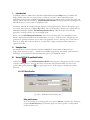
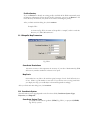
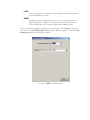
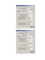
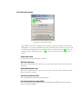
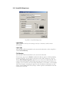
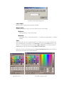
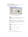
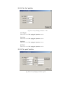
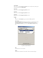
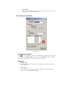
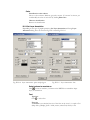
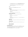
SICOM Shape DataProfiler
User’s Manual
Table of Content
I. Introduction ............................................................................................................................................................4
II. Sample Data ............................................................................................................................................................4
III.
Using SICOM ShapeDataProfiler...................................................................................................................4
III.1 RITI Data Profiler.............................................................................................................................................4
Data profile name...................................................................................................................................................4
Profile directory......................................................................................................................................................5
III. 2 Shapefile Map Parameters...............................................................................................................................5
Coordinate Resolutions .........................................................................................................................................5
Map Scale.................................................................................................................................................................5
III.3 Coordinate System ...........................................................................................................................................5
Coordinate System Type .......................................................................................................................................5
LLDG..................................................................................................................................................................6
NEMR .................................................................................................................................................................6
III.4 Data Profile Layers............................................................................................................................................8
Create New Layer...................................................................................................................................................8
Edit Selected Layer.................................................................................................................................................8
Removed Selected Layer .......................................................................................................................................8
Save Data Profile and Exit....................................................................................................................................8
Save Data Profile and Open SDM ......................................................................................................................8
III.5 Create/Edit Shape Layer.................................................................................................................................9
Layer Name .............................................................................................................................................................9
Layer Type...............................................................................................................................................................9
File Directory ..........................................................................................................................................................9
Layer Visible..........................................................................................................................................................10
Display Scale .........................................................................................................................................................10
Minimum...........................................................................................................................................................10
Maximum ..........................................................................................................................................................10
Color.......................................................................................................................................................................10
III.5.1 Edit Display Attributes ..........................................................................................................................11
III.5.1.1 For “polygon” primitive ................................................................................................................11
Fill Pattern....................................................................................................................................................11
Line Weight..................................................................................................................................................11
Line Style ......................................................................................................................................................11
Cap Style .......................................................................................................................................................11
Join Style.......................................................................................................................................................11
Border Color................................................................................................................................................11
III.5.1.2 For “line” primitive ........................................................................................................................12
Line Weight..................................................................................................................................................12
Line Style ......................................................................................................................................................12
Cap Style .......................................................................................................................................................12
Join Style.......................................................................................................................................................12
III.5.1.3 For “point” primitive .....................................................................................................................12
Line Weight..................................................................................................................................................13
Line Style ......................................................................................................................................................13
Cap Style .......................................................................................................................................................13
Join Style.......................................................................................................................................................13
Symbol ..........................................................................................................................................................13
Id ...............................................................................................................................................................13
Get Symbol..............................................................................................................................................13
Size ............................................................................................................................................................13
Angle.........................................................................................................................................................13
Constant Size...........................................................................................................................................14
III.5.2 Set Layer Classification ..........................................................................................................................14
Select column to classify.................................................................................................................................14
Classify by .........................................................................................................................................................14
Unique values...............................................................................................................................................14
Value ranges .................................................................................................................................................14
Color ..................................................................................................................................................................15
Classification color scheme .......................................................................................................................15
Remove classification .................................................................................................................................15
III.5.3 Set Layer Annotation...............................................................................................................................15
Select column to annotate on ........................................................................................................................15
Font....................................................................................................................................................................15
Type face ......................................................................................................................................................15
Font size .......................................................................................................................................................15
Color ..................................................................................................................................................................16
Alignment..........................................................................................................................................................16
Vertical..........................................................................................................................................................16
Horizontal ....................................................................................................................................................16
Annotation Display Scale ...............................................................................................................................16
Minimum ......................................................................................................................................................16
Maximum .....................................................................................................................................................16
Stretch text........................................................................................................................................................16
Fit text to curve................................................................................................................................................16
Remove Annotation........................................................................................................................................16
III.5.4 Set Primary Key ............................................................................................................................................16
Select column for Primary Key.................................................................................................................17
IV.
Contacting RITI...............................................................................................................................................17
I.
Introduction
In addition to data in CARIS format, SICOM 3.2 (Spatial Information COMponents) can handle and
display ESRI’s shape data in its native format, i.e. without conversion. Most spatial information
applications require careful compilation and artistic presentation of multiple layers of shape data. This task
could be tedious and time-consuming. SICOM ShapeDataProfiler is a data preparation tool designed for
SICOM developers’/ artists’ effort to simplify this task.
Technically, SICOM will interpret multiple shape files and their presentations based on descriptions given
in a text file with extension .saf (Spatial Agent File). The .saf file provides a default view of spatial data for
SDM (SICOM Display Module). SICOM ShapeDataProfiler provides developer an user friendly
approach to creating a profile, .saf , for each application.
Before you start SICOM ShapeDataProfiler, make sure that all shape files to be included have same
Datum. The Datum information will be needed when you create a .saf the first time. This practice will
guarantee the spatial presentation of your data is cartographically correct. Although it is not necessary to
have all you shape files under one directory, it is advisable to design a simple hierarchical database to
organize these files.
II.
Sample Data
The sample data is a subset of data developed by MASSGIS, Commonwealth of Massachusetts.
(http://www.state.ma.us/mgis/). All data are is in ESRI’s shape format. The Datum is Massachusetts
State Plane. If you need more data and information, please visit MASSGIS website.
III. Using SICOM ShapeDataProfiler
Clicking icon,
, to start SICOM ShapeDataProfiler. This program is designed to provide you with a
sequence of dialog boxes so that you don’t have to memorize the procedural details. To return to the
previous dialog box , please click
at the upper right corner. In this chapter, each dialog box will be
discussed.
III.1 RITI Data Profiler
Fig. III.1-1 RITI Data Profiler Dialog boz
Data profile name
If you are working on an exiting profile, you could use Browse to find the file. Otherwise,
complete Profile directory first, and then specify the name of profile (.saf file) without
the file extension “saf”.
Profile directory
If you use Browse to identify an existing profile, this field will be filled automatically with
the directory information for the chosen profile. Otherwise, type in or use Browse to fill
in the directory information (only down to the folder containing the profile).
After you finish with this dialog box, click continue.
Example III-1:
As shown in Fig. III-2, the name of the profile is “sample”, and it is under the
directory “C:\Data\Massachusetts”
III. 2 Shapefile Map Parameters
Fig. III.2-1
Coordinate Resolutions
The unit is in meter. This represents the accuracy of your data. Mathematically, SDM
will treat any numbers within this tolerance to be equal.
Map Scale
this number has very little to do with the typical concept of scale. It will affect the size
of text. 5000 is a good number to start with. If you feel the text is too big\small after
you display the map, you could adjust it downward\upward accordingly.
After you finish with this dialog box, click continue.
III.3 Coordinate System
The information on this page depends on the first three fields, Coordinate System Type,
Projection, and Ellipsoid.
Coordinate System Type
you could choose between geodetic (LLDG, Fig. III.3-1) or projected (NEMR,
Fig. III.3-2) systems.
LLDG
choose the appropriate ellipsoid from a large collection of ellipsoid listed in the
pull-down window for you data.
NEMR
depending on what type of projection you choose, you will need to fill in all
required parameters. Fig.III.3-2 is for Massachusetts State Plane coordinate
system, and Fig. III.4-3 is for Taiwan 2-degree TM coordinate system.
After you fill in all cartographic information on this dialog box, click continue. If there is no
layer created yet, Creat/Edit shape Layer (Fig. III.5-1) dialog box appears. Otherwise, Data
Profile Layers (Fig. III.4-1) dialog box appears.
Fig. III.3-1 LLDG Coordinate System
Fig. III.3-2 NEMR Coordinate system – Massachusetts State Plane
Fig. III.3-3 NEMR coordinate system – Taiwan 2 –degree TM
III.4 Data Profile Layers
Fig. III.4-1 Data Profile Layers
The window on the top of this dialog box, referred to as priority window, shows all the
defined layers. Layers are ordered in the order to be drawn, that is the layer at the top will
be drawn first. Remember the layer drawn could be covered by the layer drawn later. To
change the order, clicking the layer, use
down.
to move up that layer and use
to move
Create New Layer
See Section III.5, when this button is clicked.
Edit Selected Layer
This button will become active, when a layer is chosen. See Section III.5, when this button
is clicked.
Removed Selected Layer
This button will become active, when a layer is chosen. The chosen layer will be removed,
when this button is clicked.
Save Data Profile and Exit
Save the edited data profile and exit the program.
Save Data Profile and Open SDM
Save the edited data profile and open SDM to display the profiled data This provides an
interactive editing capability
III.5 Create/Edit Shape Layer
Fig. III.5-1 Create/Edit Shape Layer
Layer Name
Type in a name for this layer for creating a new layer. Otherwise, it will be shown
automatically.
Layer Type
This field will be filled automatically by the system in the edit mode or after a shape file is
selected in File Directory
File Directory
This field will be filled automatically by the system in the edit mode.
For new layer, type in or Use Browse to identify the directory path to a folder containing
the desired shape file. If more than one file exists in that folder, a dialog box (Fig. Fig.
III.5-2), Select Shape/Image File, appears for you to choose one single shape file. You
could use the absolute path or relative path with respect the location of your .saf file. For
example, if your .saf file is in the same folder, Massachusetts, as the folder, “town boundary
with coast\townsp1” containing the shape file , then only directory information you will
need is “town boundary with coast\townsp1”. Relative path is recommended so that data
could easily be relocated.
Fig. III.5-2 Select Shape/Image File
Layer Visible
The layer will be visible, when this field is checked.
Display Scale
Allows you to specify a range of scale on which the layer will be visible.
Minimum
the larger scale (1: scale1), fill in scale1
Maximum
the smaller scale (1: scale2), fill in scale2. “-1” to denote no upper limit, i.e. visible in
all scales.
Color
This will set the color of the graphic primitive, i.e. symbol color for “point”, line color for
“line”, and filled color for polygon. Click Set Color to bring up the color dialog box, Fig.
III.5.3-3. You could choose the color from the Basic color pallet, or from the extensive
color dialog box (Fig. III.3-4) by clicking Define Custom Color.
After color is chosen, click ok to return to Create/edit shape layer dialog box. The R, G,
B values for the chosen color will be displayed.
Fig. III.5-3 Color
Fig. III.5-4 extensive color
III.5.1 Edit Display Attributes
Click this button to bring up Layer Display Attributes dialog box . The information on
this dialog box depends on the type of the graphic primitive.
III.5.1.1 For “polygon” primitive
Fig. III.5.1-1 Layer Display Attributes
Fill Pattern
Click
to make your choice from a menu of filled patterns, “none”, “solid”,
“backward diagonal lines”, “crossed pattern”, “diagonal crossed pattern”,
“forward diagonal lines”, “horizontal lines”, and “vertical lines.”
Line Weight
Determine the thickness of the border of a polygon. The thickness of the line
remains constant throughout all scales, i.e. non-scaleable line. This value could
be floating. Since it is not directly correlated with a physical quantity, it is
suggested to start with “1”. If the value sets to zero, the system will provide the
minimal drawable thickness.
Line Style
to choose the style of the line: dash, dot, none and solid. Choose
Click
“none”, if you don’t need the border.
Cap Style
Click
to choose the cap style: butt, projected, round
Join Style
Click
to choose the join style: bevel, miter, round
Border Color
Choose border color. See Color
Hit continue to go back to the Create/Edit Shape Layer dialog box.
III.5.1.2 For “line” primitive
Fig. III.5.1-2 Layer Display Attributes – Line
Line Weight
Please refer to the For “polygon” primitive section.
Line Style
Please refer to the For “polygon” primitive section.
Cap Style
Please refer to the For “polygon” primitive section.
Join Style
Please refer to the For “polygon” primitive section.
III.5.1.3 For “point” primitive
Fig. III.5.1-3 Layer Display Attributes –point
Line Weight
Please refer to the For “polygon” primitive section. A default value will be given
for a chosen symbol from Get Symbol.
Line Style
Please refer to the For “polygon” primitive section.
Cap Style
Please refer to the For “polygon” primitive section.
Join Style
Please refer to the For “polygon” primitive section.
Symbol
Id
Type in or use Get Symbol to get the desired CARIS symbol ID
Get Symbol
Bring up Symbol Browser dialog box (Fig. III.5.1-4), scroll down the symbol
description window to choose (highlight) the desired symbol, and click
Select Displayed Symbol to get back to Layer Display Attributes dialog
box.
Fig. III.5.1-4 Symbol Browser
Size
Determine the size of the symbol.
Angle
Determine the orientation of the symbol. Enter the number in degree.
Constant Size
If checked, the symbol will remain the same size throughout all scale. This
option is not currently implemented.
III.5.2 Set Layer Classification
Fig. III.5.1-5
Select column to classify
Click to select an attribute, a column on the DBF file associated the shape layer, for
classification. If Unique values on the section of the Classify by panel is checked,
only columns with unique value will be available for selection.
Classify by
Unique values
Classify the primitives for the given layer according to the unique value of the
chosen attribute.
Value ranges
Classify the primitives for the given layer according to classes defined by the
chosen classes in the Number of ranges.
Color
Classification color scheme
Choose a color scheme: Rainbow, grayscale, custom. If “custom” is chosen, you
could modify the color of each class by clicking Edit Color.
Remove classification
Remove the classification
III.5.3 Set Layer Annotation
Depending on the type of graphic primitives, Set Layer Annotation will bring Layer
Annotation dialog boxes as shown in Fig. III.5.1-6 and Fig. III.5.1-7.
Fig. III.5.1-6 Layer Annotation –point and polygon
Fig. III.5.1-7 Layer Annotation –line
Select column to annotate on
Click to select an attribute, a column on the DBF file associated the shape
layer, for annotation.
Font
Type face
Click to select font
Font size
If constant is not checked, the size of the font on the view, S, is equal to D *
(Map Scale)/(Display_Scale * 1000) meters, where D (in meter) is the
chosen Font size, Map Scale chosen on shapefile Map Parameters dialog
box, and (Display Scale) is the view scale (1: Map_Scale) on the monitor.
Otherwise, the size of the font, S, is equal to D/1000, on the monitor
throughout all display scales.
Color
See Color on Create/Edit Shape Layer (Section III.5)
Alignment
Verticle
Center, bottom and top of the reference point or line, where centroid for the
polygon and the location of the point.
Horizontal
Center, left and right of the reference points or line.
Annotation Display Scale
Specify a range of scale on which the annotation will be visible.
Minimum
the larger scale (1: scale1), fill in scale1
Maximum
the smaller scale (1: scale2), fill in scale2. “-1” to denote no upper limit, i.e.
visible in all scales.
Stretch text
This only applies to “line” primitive. If checked, the text will be stretched to the
length of the line.
Fit text to curve
This only applies to “line” primitive. If checked, the text will fit the curve of a
line.
Remove Annotation
Remove the annotation.
III.5.4 Set Primary Key
This is designed to speed up query by identifing a column of the DBF file with a unique
value for each graphic primitive (each row). If there is no column with unique value, a
warning dialog boxes appear (Fig. III.5.1-7, -8). You could click ok to continue.
Otherwise, Set Primary Key (Fig. III.5.1-9) dialog box appears.
Fig. III.5.1-7 Warning message
Fig. III.5.1-8 Warning message
Select column for Primary Key
Select a column for primary key.
Fig. III.5.1-9 Set Primary Key
IV. Contacting RITI
Should you encounter any difficulties while running SICOM DataProfiler, please contact us:
E-mail:
Fax:
Address:
[email protected],
781 942 2161
274 Main Street, Suite 302,
Reading, MA 01867 USA
Our technical and customer service people will respond to you immediately once your report is received.