1
ISSN: 2321-7782 (Online)
Volume 2, Issue 6, June 2014
International Journal of Advance Research in
Computer Science and Management Studies
Research Article / Survey Paper / Case Study
Available online at: www.ijarcsms.com
Remote Video surveillance System Based on S3C2440 and
GPRS
Ayesha M. Anwar Khan1
Prof. Chanchal V. Dahat2
Dept. of Computer Science and Technology
Nagpur Institute of Technology
Nagpur – India
Dept. of Electronics and Telecommunication
Nagpur Institute of Technology
Nagpur – India
Prof. Dinesh Katole3
Dept. of Electronics and Telecommunication
Nagpur Institute of Technology
Nagpur – India
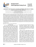
Abstract: In this paper a wireless robust system for video monitoring is designed using ARM9 core and GPRS connectivity.
Client server architecture is employed in which S3C2440, webcam and GPRS module is on server side and client side is the
monitoring device. Programming is done using DOT NET coding. The image is captured using a webcam, compressed and
transmitted to the monitor client both via MMS and email. The received image is decompressed using JPEG and viewed in
real time. A novel system can be used as per the requirement. Most effective for applications where it is difficult for humans
to reach.
Keywords: S3C2440, GPRS, Linux Fedora, JPEG, MMS.
I. INTRODUCTION
With the advancements in the embedded system, networking and communications technology, the video monitoring systems
are playing a major role in today’s world, especially in the military, industrial and civilian security applications. Traditional
video surveillance can generally achieve close distance monitoring, by using the PC as a monitoring unit connected to
surveillance camera with coaxial cable. These video surveillance systems are broadly classified into analog and digital video
surveillance systems. But today in this digital world, the video surveillance systems based on embedded technology are more
advantageous compared to the traditional surveillance systems, as it provides high performance at low cost and good stability.
Meanwhile, it possess some advantages, for example, enhanced design simplicity, compact construct, portable, low power
consumption, long-distance transmission This paper puts forward a video surveillance system based on ARM9 architecture
based S3C2440 controller which is an Friendly ARM platform.
Video data is captured using a USB web camera, compressed into JPEG format, transferred through the 3G network under
the control of the ARM9 chip; then, the monitor client will receive the data frames which are later compressed to restructure,
and recompose video images. To demonstrate mobility the server is placed on a robot model which will take a square path and
capture an image.
The video capture is the core part of the system. The camera capture video images, this data is compressed, and transferred
into a video stream format. GSM transceiver module is used for GPRS wireless network module [2] [3].
© 2014, IJARCSMS All Rights Reserved
44 | P a g e
Ayesha et al.
International Journal of Advance Research in Computer Science and Management Studies
Volume 2, Issue 6, June 2014 pg. 44-52
WEB
CAMERA
A
ARM9
ROBOT
MODEL
(S3C2440)
GPRS
GPS
RECIEVER
MODULE
RECEIVER
Front end
application in
system
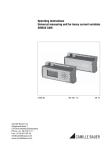
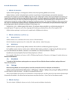
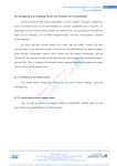
Fig. 1. Basic block diagram of proposed video surveillance system
Images are transmitted on MMS and email via GPRS network. The system can be applied in smart anti-theft, dynamic
transportation, smart home for security, medical treatment, as well as in all kinds of video surveillance systems. The system
structure is shown in Figure 1. Compared with video capture systems based on the digital signal processor (DSP), this system
has the advantages of fewer and simplified modules, cost effective, enhanced intelligence, greater system stability and higher
security.
II. DESIGNING THE HARDWARE
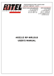
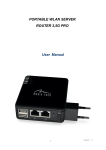
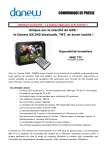
Block Diagram of System hardware is shown in Figure 2. After comparison and research, the S3C2440 microprocessor is
regarded as the main chip for video capture and processing. The S3C2440 offers outstanding features with its CPU core, 16/32
bit ARM920T RISC processor designed by Samsung, Ltd equipment as well as is cost-effective and requires less power. The
chip implements MMU (memory management unit), AMBA (advanced microcontroller bus architecture), BUS, and Harvard
cache architecture with separate 16kB instruction and 16Kb data caches, each with 8-word line length long. It has 1-port USB
Device and 2 port USB Host, support 64MB Flash and 64 MB SDRAM memory cell.
Fig. 2. Block Diagram of System hardware
A. ARM920T processor
ARM920T processor is used in our model due to its advanced features described below. Samsung S3C2440 32-bit ARM
processor is the contemporary general purpose microprocessor in the embedded market used in industrial level applications.
ARM9 consists of a number of peripherals interfaced to it. We use LCD display, keypad matrix, UARTS, GPIO and I2C
protocol. ARM9 processor is a link between GPS and GSM modules for communication. The description of ARM9 is discussed
in further sections.
FEATURES:
32-bit ARM920T microcontroller 400MHz, max. 533Mhz
© 2014, IJARCSMS All Rights Reserved
ISSN: 2321-7782 (Online)
45 | P a g e
Ayesha et al.
International Journal of Advance Research in Computer Science and Management Studies
Volume 2, Issue 6, June 2014 pg. 44-52
64MByte SDRAM, 32bit Bus, 100MHz Clock.
64MByte or 128MByte NAND Flash, 2MByte NOR Flash with Bios
In-System Programming (ISP) and In-Application Programming via on-chip boot-loader software. Single sector or full
chip erase takes 400ms.
B Two 32-bit timers (with 4 capture and 4 compare channels), PWM timer (4 channel), Real Time Clock and
Watchdog.
Multiple serial interfaces including three UARTs (1 RS232), I2C 20C08 EEPROM (1024bytes) and two SPIs 60MHz
maximum CPU clock available from programmable on-chip Phase-Locked Loop.
On-chip system clock is of 12 MHz crystal.
OS support: Linux2.6, Android, Windows CE 5and6.
Two low power modes Power down and Idle.
Processor wake-up from Power-down mode via external interrupt.
B. GPRS communication module
General Packet Radio Services (GPRS) is a packet oriented mobile data service on 2G and 3G cellular communication
system’s global system for mobile communication (GSM). GSM is the most widely used mobile technology using a simple
Subscriber Identity Module (SIM) it has taken the world of mobile communication to new heights. Even with the introduction
of new technologies like CDMA, GSM has stood its strength due to its efficiency and simplicity.
A GSM modem is a wireless modem that works with a GSM wireless network. Computers use AT commands to control
modems. Both dial-up modems and GSM modems support a common set of standard AT commands. So we can use a GSM
modem just like a dial-up modem. The difference between them is that a dial-up modem sends and receives data through a fixed
telephone line while a wireless modem sends and receives data through radio waves.
The following AT commands are used:
Goal: Call a phone
Dial 123-456-7890 = ATD1234567890;\r
This command returns OK or ERROR. Returns NO CARRIER when phone hangs up
Goal: Send a text
AT+CMSF=1\r
Find message
Returns OK or ERROR
AT+CSCS= “GSM”\r
Select TE Character Set
Returns OK or ERROR
AT+CSCA= “+13123149810”\r Service Center Address
Returns OK or ERROR. This number +13123149810 is the short message center for AT&T/Singular service. T-Mobile’s is
+12063130004
AT+CSMP=17, 167, 0,240\r Set Text Mode Parameters
Returns OK or ERROR. These numbers refer to settings for text message sending.
© 2014, IJARCSMS All Rights Reserved
ISSN: 2321-7782 (Online)
46 | P a g e
Ayesha et al.
International Journal of Advance Research in Computer Science and Management Studies
Volume 2, Issue 6, June 2014 pg. 44-52
Send Message
AT+CMGS= ‘1234567890”\r
Returns>, prompting what message to send. 1234567890 is the phone number the text will be sent to.
Hello this is a message<Ctrl+z>
Type any message, and then press <Ctrl+z>. Returns conformation message and Message ID number
Goal: Read a text
AT+CMGF=1\r
Preferred Message Format
Returns OK or ERROR
AT+CMGDA= “DEL ALL”
Delete all text
AT+CNMI=0, 0
New Message Indication
Disable unsolicited error code
AT+CMGR=1
Read Message
Read Message #1
AT+CMGL= “REC UNREAD”
List Message
Read all received unread messages
GSM is one of the most vital components in our set up since all the communication between the users and Centralized unit
takes place through this modem. GSM communicates with ARM through I2C bus.
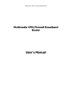
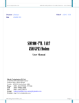
Fig. 3. Interfacing circuit with 6-pin SIM card.
The single supply voltage range is 3.4V-4.5V. Its current consumption is as low as 1.5mA in SLEEP mode. Normal
operating temperature range is -30˚C to +80˚C which are best suited for this application which will be used in places where
human reach is difficult.
GSM module SIMCOM SIM900A is used. SIM900A is a quad-band GSM/GPRS engine which works on frequencies GSM
850MHz; EGSM 900MHz and PCS 1900MHz. SIM900 features GPRS multi-slot class 10/ class 8 and supports the GPSR coding
Schemes CS-1, CS-2, CS-3 and CS-4. This GSM module is interfaced with a 6pin SIM card. AT commands are used to get
information in SIM card.
C. Global Positioning System (GPS)
GPS is wireless communication module. This design adapts the current leading GPS technology and the integrated
positioning chip Cirocomm 600L. Specifically Designed for OEM Applications, it is a GPS receiver module with high
sensitivity, low power consumption, and 51 channels. Com- pared with other independent GPS solutions GPS600L is able to
© 2014, IJARCSMS All Rights Reserved
ISSN: 2321-7782 (Online)
47 | P a g e
Ayesha et al.
International Journal of Advance Research in Computer Science and Management Studies
Volume 2, Issue 6, June 2014 pg. 44-52
help users gain and continuously track GPS signals at a very low signal intensity, which means GPS600L can be used in the
environment where it has never been thought to be accessible, such as buildings of the city, dense forest, garage, and many
indoor environment, with a position accuracy of less than 10 meters. With only an addition of relevant circuit at the periphery,
longitude, latitude, positioning information including time, rate, moving direction, etc., can be output through the serial.
The GPS module can receive data when connected to ARM9 development-board through RS232port. When the ARM9 chip
sends the instruction AT to GPS module, the GPS module starts receiving the data and saves it into memory. This instruction
sends the region information to the support-server center through GSM net. Because the system is based on GPS data which is
sent through GPRS net, it must be initiated at first.
The GPS is initialized as:
private void textBox3_TextChanged(object sender, EventArgs e)
{
buffer = textBox3.Text;
try
{
gps = buffer.Substring(0, 200);
buffer = "";
if (gps.Length >= 200)
{
for (i = 0; i < 200; i++)
{
Thread.Sleep(100);
if (gps.Substring(i, 6) == "$GPRMC")
{
textBox4.Text = gps.Substring(i + 20, 9);
textBox2.Text = gps.Substring(i + 32, 10);
textBox3.Text = "";
gps = "";
timer2.Enabled = false;
still();
upload();
send();
timer1.Enabled = true;
}
}
© 2014, IJARCSMS All Rights Reserved
ISSN: 2321-7782 (Online)
48 | P a g e
Ayesha et al.
International Journal of Advance Research in Computer Science and Management Studies
Volume 2, Issue 6, June 2014 pg. 44-52
}
}
D. JTAG circuit
IEEE 1149.1 commonly known as JTAG (Joint Test Action Group) is an international standard test protocol. It is mainly
used for chip internal test, system simulation and debugging [4][5]. JTAG technology is an embedded debugging technique.
Inside the chip it packages a special test circuit TAP (Test Access Port). It uses the dedicated JTAG test tools to test the internal
nodes [6][7].
Fig. 4. The JTAG interface circuit
The most complex devices present till now such as FPGA, ARM, and DSP etc support JTAG protocol. The standard JTAG
interface is 4-wire: TMS, TCK, TDI, and TDO [10]. They are test mode select, test clock, test data input and test data output [8].
JTAG is a simple and efficient means of developing and debugging embedded systems as all the internal parts can be accessed
through JTAG interface. At present there are two standards to connect the JTAG interface: 14 pin connector and 20 pin
connector. This design uses a 20-pin JTAG interface. The system's JTAG interface circuit is shown in Fig 4.
III. SOFTWARE DESIGN
A. The image capturing process
The core of the entire video capture module is video capture. First the camera is initialized using the following:
private void cmdConnect_Click(object sender, EventArgs e)
{
cam_.setMediaType(resolutionCombo.SelectedIndex);
if (!cam_.init())
{
MessageBox.Show("Cannot Init camera");
}
}
The video capture is finished once the robot model completes a square path. The OV511 chip with built-in drive is used in
the system [1]. Driver loading process is as follows: making menuconfig in the kernel directory, and then selecting the Video
© 2014, IJARCSMS All Rights Reserved
ISSN: 2321-7782 (Online)
49 | P a g e
Ayesha et al.
International Journal of Advance Research in Computer Science and Management Studies
Volume 2, Issue 6, June 2014 pg. 44-52
for Linux USB support directory, and support for USB and USB camera the OV511 support, finally save and exit. The program
can be loaded successfully and the system starts with the new kernel after running the OV511. O.
The system functions are as follows:
DirectShowNETCF.Camera.Camera cam_ = null;
private void capTypeCombo_SelectedIndexChanged(object sender, EventArgs e)
{
cam_.CapType = (DirectShowNETCF.Camera.CaptureType)capTypeCombo.SelectedIndex;
}
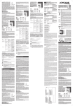
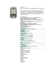
The external device is managed by the device file in the Linux operating system. So, the operations of external devices are
transformed into the operation of the device files. The main process is shown in Figure 5.
After the above steps, the camera video data is acquisited into memory. First the video data of collection is compressed into
JPEG. Then the data is packaged into the data packet transmission to the video application server for processing.
Fig. 5. The image capturing process
B. Video compression
The JPEG compression encoding scheme is used in the system based on the DCT (Discrete Cosine Transform) sequence.
The original image is divided into 8 × 8 small video image after DCT transform. The low frequency components are
concentrated in the upper left corner, and high-frequency components are in the lower right corner (DCT transform is actually a
low-pass filter of the spatial domain).
The high spatial frequency for the human eye is far from low-frequency sensitive, so the treatment of visual loss is very
small. The video image is clear and true by the method. The data is quantified after DCT. The quantization is a value divided by
the quantization table corresponding value. Due to the smaller value of the upper-left corner of the quantization table, the value
of the upper right corner on the upper left corner of the low frequency components can be maintained, high-frequency
component can be fully inhibited. After Quantified at high spatial frequencies a large numbers of consecutive zero will appear.
The coding process is used. The system uses Huffman variable length coding to encode the quantized DCT coefficients, so that
the entropy is minimum. The JPEG encoding under Linux can use the library Libjpeg, that is used under Linux standard library,
and its function is the picture in accordance with a certain percentage of compressed into JPEG format pictures or JPEG format
to decompress. Much software operating on JPEG are based on this library.
© 2014, IJARCSMS All Rights Reserved
ISSN: 2321-7782 (Online)
50 | P a g e
Ayesha et al.
International Journal of Advance Research in Computer Science and Management Studies
Volume 2, Issue 6, June 2014 pg. 44-52
C. Program design- Communication module
The client and server programming are the two parts of system programming. This system adopts a very simple approach of
client and server program. The server program realizes the data collection, encoding and sending while the client program
completes the data reception, decoding and display. At the client side Linux Fedora 50 operating system is used on which
internet is accessed on QT creator based on QT platform. For communication between client and GPRS networking is used. In
order to distinguish between different application processes and connections, many computer operating systems provide for the
application by TCP / IP protocol. This interact is called the socket. Its main parameters are three: the destination IP address,
transport layer protocol and port number. These three parameters can be distinguished from a different application process or a
network connection communication, concurrent services of data transmission. The system uses the stream socket design whose
communication process is shown in Figure 6.
Fig. 6. The TCP communication process between C/S
D. Program design- Server side
The server program realizes the data collection, encoding and sending while the client program completes the data reception,
decoding and display. Coding at the server side is done in CSharp using Windows Embedded compact OS, commonly known as
WinCE.
E. Program design- Client side
First its IP address is obtained by the domain name server, and then a socket is created. The data is received from the server
after connection is successful by connect function; finally the socket is closed after the communication is finished.
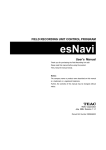
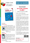
IV. EXPERIMENTAL RESULTS AND ANALYSIS
The system is stable. Size is adjusted after compression; and frame rate can be improved.
The result is obtained from the experimental data.
1. The transmission rate is varied; with the changes of the network.
2. The image is smooth due to USB driver. The performance can be raised by improving the USB.
3. Stability of the system is achieved.
© 2014, IJARCSMS All Rights Reserved
ISSN: 2321-7782 (Online)
51 | P a g e
Ayesha et al.
International Journal of Advance Research in Computer Science and Management Studies
Volume 2, Issue 6, June 2014 pg. 44-52
Fig. 7. Image received wirelessly on email.
V. CONCLUSION
Now-a-days video monitoring is not only used for security purpose but also can be used in many other applications such as,
searching lost ones from mountain ranges, in coal mines, or for making wildlife documentaries. The future scope of this project is
with different advancements according to the requirement. The proposed system is based on ARM9 with GPRS and GPS
connectivity which allows real time data transfer. Also the problem of range for data transfer is overcome by using internet
connectivity through GPRS. Thus the system is reliable, stable and can be used in most critical conditions.
ACKNOWLEDGEMENT
I acknowledge Prof. Chanchal V. Dahat, HOD-ETC department and Prof. Dinesh Katole for their guidance and suggestion.
References
1.
Lihui Zhao,Chunbao Huo, Hongzhe Yang “ The Design of Remote Video Monitoring System Based on S3C2416 and GPRS” proc. Of International
Conference on System Science and Engineering, June 30-July 2, 2012 Dalian, China, IEEE.
2.
K. Sandeep Kumar, P. Sudhakar, R. Shivaji “ Design of ARM-Linux based Video Surveillance System” International Journal of Engineering Research and
Development, Volume 4, Issue 10 (November 2012).
3.
R. Anil Kumar, G. Jyothirmai, K. RameshBabu “Design and Development of Arm Based Embedded Intelligent Public Transport Vehicle Position
System” International Journal of Internet Computing ISSN No: 2231 – 6965, VOL- 1, ISS- 3 2012.
4.
Zhou, L.G., 2005. ARM Embedded System Software Development Instance. Beihang University Press, Beijing.
5.
Wei, K.J., C.Y. Yang and H. Li, 2011. Surface meteorological data collector based on ARM embedded system. Microcomput. Infor., 27(12): 53-54.
6.
Li, J.W. and H.J. He, 2011. Skin-hearing systems designs based on ARM. Comp. Eng. Design, 32(1): 107-284.
7.
Ji, W.K., J. Yang and Y.Q. Hong, 2007. BSP development of WinCE system for vehicle navigation device based on S3C2440. Proceedings of the 8th
Electronic Measurement and Instruments, pp: 389-391.
8.
Shi, J.J., 2008. ARM9 based embedded Linux Transplantin. J. Wuhan Univ. Technol., 30(2): 205-208.
9.
Micro2440 user manual-2010-3-8, Guangzhou: Guangzhou friendly arms of computer science and technology Co., LTD, 2010 arms of computer science
and technology Co., LTD, 2010.
10.
Jinbiao Hou “ARM Core Unit Design of a remote Video Monitoring System” Research journal of applied sciences, engineering and technology, 5(18):
4493-4498, May 2013.
© 2014, IJARCSMS All Rights Reserved
ISSN: 2321-7782 (Online)
52 | P a g e