1
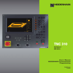
TNC 310
NC-Software
286 040-xx
User’s Manual
Conversational
Programming
7/2000
Controls on the TNC
Controls on the visual display unit
Split screen layout
Soft keys
Machine control buttons
Axis direction buttons
Rapid traverse button
Spindle rotation direction
Coolant
Change arithmetic sign
Confirm entry and resume dialog
End block
Clear numerical entry or TNC error message
Abort dialog, delete program section
MOD functions
Spindle ON/OFF
NC start/NC stop
Override control knobs for feed rate/spindle speed
100
100
50
150
S %
0
Numbers
Programming aids
Tool release
150
...
Decimal point
Shift soft-key rows
50
Coordinate numbers, editing
HELP functions
Moving the cursor, going directly to blocks, cycles and
parameter functions
Move highlight
Move highlight, skip dialog question
F %
0
Machine operating modes
MANUAL OPERATION
POSITIONING WITH MDI
PROGRAM RUN, SINGLE BLOCK
PROGRAMMING AND EDITING
Select blocks and cycles directly
Contents
TNC Models, Software and
Features
This manual describes functions and features provided by
the TNCs with the following NC software number.
TNC Model
NC Software No.
TNC 310
286 040 xx
The machine tool builder adapts the useable features of the
TNC to his machine by setting machine parameters. Therefore, some of the functions described in this manual may
not be among the features provided by your machine tool.
TNC functions that may not be available on your machine
include:
■ Probing function for the 3-D touch probe
■ Digitizing option
■ Tool measurement with the TT 120
■ Rigid tapping
Please contact your machine tool builder to become familiar
with the individual implementation of the control on your
machine.
Many machine manufacturers, as well as HEIDENHAIN,
offer programming courses for the TNCs. We recommend
these courses as an effective way of improving your
programming skill and sharing information and ideas with
other TNC users.
Location of use
The TNC complies with the limits for a Class A device in
accordance with the specifications in EN 55022, and is
intended for use primarily in industrially-zoned areas.
HEIDENHAIN TNC 310
I
Contents
Contents
Introduction
Manual Operation and Setup
Positioning with Manual Data Input (MDI)
Programming: Fundamentals of NC,
File Management, Programming Aids
Programming: Tools
Programming: Programming Contours
Programming: Miscellaneous Functions
Programming: Cycles
Programming: Subprograms and Program
Section Repeats
Test Run and Program Run
3-D Touch Probes
MOD Functions
Tables and Overviews
HEIDENHAIN TNC 310
III
1
2
3
4
5
6
7
8
9
10
11
12
13
Contents
1 INTRODUCTION 1
1.1 The TNC 310 2
1.2 Visual Display Unit and Keyboard 3
1.3 Modes of Operation 4
1.4 Status Displays 7
1.5 Accessories: HEIDENHAIN 3-D Touch Probes and Electronic Handwheels 11
2 MANUAL OPERATION AND SETUP 13
2.1 Switch-On 14
2.2 Moving the Machine Axes 15
2.3 Spindle Speed S, Feed Rate F and Miscellaneous Functions M 18
2.4 Datum Setting (Without a 3-D Touch Probe) 19
3 POSITIONING WITH MANUAL DATA INPUT (MDI) 21
3.1 Programming and Executing Simple Positioning Blocks
22
4 PROGRAMMING: FUNDAMENTALS OF NC, FILE MANAGEMENT, PROGRAMMING AIDS 23
4.1 Fundamentals of NC 24
4.2 File Management 29
4.3 Creating and Writing Programs 32
4.4 Interactive Programming Graphics 37
4.5 HELP Function 39
5 PROGRAMMING: TOOLS 41
5.1 Entering Tool-Related Data 42
5.2 Tool Data 43
5.3 Tool Compensation 48
IV
Contents
Contents
6 PROGRAMMING: PROGRAMMING CONTOURS 53
6.1 Overview of Tool Movements 54
6.2 Fundamentals of Path Functions 55
6.3 Path Contours — Cartesian Coordinates 58
Overview of path functions 58
Straight line L 59
Inserting a chamfer CHF between two straight lines 59
Circle center CC 60
Circular path C around circle center CC 61
Circular path CR with defined radius 62
Circular path CT with tangential connection 63
Corner Rounding RND 64
Example: Linear movements and chamfers with Cartesian coordinates 65
Example: Circular movements with Cartesian coordinates 66
Example: Full circle with Cartesian coordinates 67
6.4 Path Contours—Polar Coordinates 68
Polar coordinate origin: Pole CC 68
Straight line LP 69
Circular path CP around pole CC 69
Circular path CTP with tangential connection 70
Helical interpolation 71
Example: Linear movement with polar coordinates 73
Example: Helix 74
7 PROGRAMMING: MISCELLANEOUS FUNCTIONS 75
7.1 Entering Miscellaneous Functions M and STOP 76
7.2 Miscellaneous Functions for Program Run Control, Spindle and Coolant 77
7.3 Miscellaneous Functions for Coordinate Data 77
7.4 Miscellaneous Functions for Contouring Behavior 79
7.5 Miscellaneous Function for Rotary Axes 82
HEIDENHAIN TNC 310
V
Contents
8 PROGRAMMING: CYCLES 83
8.1 General Overview of Cycles 84
8.2 Drilling Cycles 86
PECKING (Cycle 1) 86
DRILLING (Cycle 200) 88
REAMING (Cycle 201) 89
BORING (Cycle 202) 90
UNIVERSAL DRILLING (Cycle 203) 91
TAPPING with a floating tap holder (Cycle 2) 93
RIGID TAPPING (Cycle 17) 94
Example: Drilling cycles 95
Example: Drilling cycles 96
8.3 Cycles for Milling Pockets, Studs and Slots 97
POCKET MILLING (Cycle 4) 98
POCKET FINISHING (Cycle 212) 99
STUD FINISHING (Cycle 213) 101
CIRCULAR POCKET MILLING (Cycle 5) 102
CIRCULAR POCKET FINISHING (Cycle 214) 104
CIRCULAR STUD FINISHING (Cycle 215) 105
SLOT MILLING (Cycle 3) 107
SLOT with reciprocating plunge-cut (Cycle 210) 108
CIRCULAR SLOT with reciprocating plunge-cut (Cycle 211)
110
Example: Milling pockets, studs and slots 112
8.4 Cycles for Machining Hole Patterns 114
CIRCULAR PATTERN (Cycle 220) 115
LINEAR PATTERN (Cycle 221)
116
Example: Circular hole patterns 118
8.5 Cycles for multipass milling 120
MULTIPASS MILLING (Cycle 230) 120
RULED SURFACE (Cycle 231) 122
Example: Multipass milling 124
VI
Contents
Contents
8.6 Coordinate transformation cycles 125
DATUM SHIFT (Cycle 7) 126
MIRROR IMAGE (Cycle 8) 127
ROTATION (Cycle 10) 128
SCALING FACTOR (Cycle 11)
129
Example: Coordinate transformation cycles 130
8.7 Special Cycles 132
DWELL TIME (Cycle 9)
132
PROGRAM CALL (Cycle 12) 132
ORIENTED SPINDLE STOP (Cycle 13)
133
9 PROGRAMMING: SUBPROGRAMS AND PROGRAM SECTION REPEATS 135
9.1 Marking Subprograms and Program Section Repeats 136
9.2 Subprograms 136
9.3 Program Section Repeats 137
9.4 Nesting 139
Subprogram within a subprogram 139
Repeating program section repeats 140
Repeating a subprogram 141
9.5 Programming Examples 142
Example: Milling a contour in several infeeds 142
Example: Groups of holes 143
Example: Groups of holes with several tools 144
10 TEST RUN AND PROGRAM RUN 147
10.1 Graphics 148
10.2 Test Run 152
10.3 Program Run 154
10.4 Optional Program Run Interruption 158
10.5 Blockwise Transfer: Running Longer Programs 158
11 3-D TOUCH PROBES 159
11.1Touch probe cycles in the operating mode MANUAL OPERATION 160
Calibrating a touch trigger probe 161
Compensating workpiece misalignment 162
11.2 Setting the Datum with a 3-D Touch Probe 163
11.3 Measuring Workpieces with a 3-D Touch Probe 166
HEIDENHAIN TNC 310
VII
Contents
12 MOD FUNCTIONS 169
12.1 Selecting, Changing and Exiting the MOD Functions 170
12.2 System Information 170
12.3 Enter Code Number 171
12.4 Setting the Data Interface 171
12.5 Machine-Specific User Parameters 172
12.6 Position Display Types 172
12.7 Unit of Measurement 173
12.8 Enter Axis Traverse Limits
173
13 TABLES AND OVERVIEWS 175
13.1 General User Parameters 176
Input possibilities for machine parameters 176
Selecting general user parameters 176
External data transfer 177
3-D Touch Probes 178
TNC displays, TNC editor 178
Machining and program run 180
Electronic handwheels 180
13.2 Pin Layout and Connecting Cable for the Data Interface 181
RS-232-C/V.24 Interface 181
13.3 Technical Information 182
TNC features 182
Programmable functions 183
TNC Specifications 183
13.4 TNC Error Messages 184
TNC error messages during programming 184
TNC error messages during test run and program run 184
13.5 Exchanging the Buffer Battery 187
VIII
Contents
1
Introduction
1.1 The TNC 310
1.1 The TNC 310
HEIDENHAIN TNC controls are shop-floor programmable
contouring controls for milling, drilling and boring machines.
You can program conventional milling, drilling and boring operations
right at the machine with the easily understandable interactive
conversational guidance. The TNC 310 can control up to 4 axes.
Instead of the fourth axis, you can also change the angular position
of the spindle under program control.
Keyboard and screen layout are clearly arranged in a such way that
the functions are fast and easy to use.
Programming: HEIDENHAIN conversational format
HEIDENHAIN conversational programming is an especially easy
method of writing programs. Interactive graphics illustrate the
individual machining steps for programming the contour. Workpiece
machining can be graphically simulated during test run.
You can also enter one program while the TNC is running another.
Compatibility
The TNC can execute all part programs that were written on
HEIDENHAIN controls TNC 150 B and later.
2
1 Introduction
1.2 Visual Display Unit and Keyboard
1.2 Visual Display Unit and Keyboard
Visual display unit
The figure at right shows the keys and controls on the VDU:
Setting the screen layout
Soft key selector keys
Switching the soft-key rows
Header
When the TNC is on, the selected operating mode is shown in
the screen header. Dialog prompts and TNC messages also
appear here (unless the TNC is showing only graphics).
Soft keys
In the right margin the TNC indicates additional functions in a softkey row. You can select these functions by pressing the keys
immediately beside them . Directly beneath the soft-key row are
rectangular boxes indicating the number of soft-key rows. These
rows can be called with the shift key. The box representing the
active soft-key row is filled in.
Screen layout
You select the screen layout yourself: In the PROGRAMMING AND
EDITING mode of operation, for example, you can have the TNC
show program blocks in the left window while the right window
displays programming graphics. You could also display help
graphics for cycle definition in the right window instead, or display
only program blocks in one large window. The available screen
windows depend on the selected operating mode.
To change the screen layout:
Press the SPLIT SCREEN key: The soft-key row
shows the available layout options.
<
Select the desired screen layout.
HEIDENHAIN TNC 310
3
1.3 Modes of Operation
Keyboard
The figure at right shows the keys of the keyboard grouped
according to their functions:
MOD function,
HELP function
Numerical input
Dialog buttons
Arrow keys and GOTO jump command
Modes of Operation
Machine control buttons
Override control knobs for feed rate/spindle speed
The functions of the individual keys are described in the foldout of
the front cover. The exact functioning of the machine control
buttons, e.g. NC START, is described in more detail in your Machine
Manual.
1.3 Modes of Operation
The TNC offers the following modes of operation for the various
functions and working steps that you need to machine a workpiece:
MANUAL OPERATION and ELECTRONIC
HANDWHEEL Operating Modes
The MANUAL OPERATION mode is required for setting up the
machine tool. In this operating mode, you can position the machine
axes manually or by increments. Datums can be set by the usual
scratching method or by using the TS 220 triggering touch probe.
The TNC also supports the manual traverse of the machine axes
using a HR electronic handwheel.
Soft keys for selecting the screen layout
There are no select options available. The TNC always shows the
position display.
4
1 Introduction
1.3 Modes of Operation
POSITIONING WITH MANUAL DATA INPUT (MDI)
This mode of operation is used for programming simple traversing
movements, such as for face milling or pre-positioning.
Soft keys for selecting the screen layout
There are no select options available. The TNC always shows the
position display.
PROGRAMMING AND EDITING
In this mode of operation you can write your part programs. The
various cycles help you with programming and add necessary
information. If desired, you can have the programming graphics
show the individual steps.
Soft keys for selecting the screen layout
Screen windows
Soft key
Program blocks
Left: program blocks, right: help graphics for
cycle programming
Left: program blocks, right: programming graphics
Interactive Programming Graphics
HEIDENHAIN TNC 310
5
1.3 Modes of Operation
TEST RUN
In the TEST RUN mode of operation, the TNC checks programs and
program sections for errors, such as geometrical incompatibilities,
missing or incorrect data within the program or violations of the
work space. This simulation is supported graphically in different
display modes. Use a soft key to activate the test run in the PROGRAM RUN operating mode.
Soft keys for selecting the screen layout
Screen windows
Soft key
Program blocks
n Test run graphics
Left: program blocks, right: general
program information
Left: program blocks, right: positions and
coordinates
Left: program blocks, right: tool
information
Left: program blocks, right: coordinate
transformations
6
1 Introduction
1.4 Status Displays
PROGRAM RUN/SINGLE BLOCK and
PROGRAM RUN/FULL SEQUENCE
In the PROGRAM RUN, FULL SEQUENCE mode of operation the
TNC executes a part program continuously to its end or to a manual
or programmed stop. You can resume program run after an
interruption.
In the PROGRAM RUN, SINGLE BLOCK mode of operation you
execute each block separately by pressing the NC START button.
Soft keys for selecting the screen layout
Screen windows
Soft key
Program blocks
Left: program blocks, right: general
program information
Left: program blocks, right: positions and
coordinates
Left: program blocks, right: tool
information
Left: program blocks, right: coordinate
transformations
1.4 Status Displays
“General” status display
The status display informs you of the current state of the machine
tool. It is displayed automatically in all modes of operation:
In the operating modes MANUAL OPERATION and ELECTRONIC
HANDWHEEL and POSITIONING WITH MDI the status display
appears in the large window .
HEIDENHAIN TNC 310
7
1.4 Status Displays
Information in the status display
Symbol Meaning
ACTL.
X Y Z
Actual or nominal coordinates of the current position
Machine axes
S F M Spindle speed S, feed rate F and active M functions
Program run started
Axis locked
ROT
Axes are moving
under a basic rotation.
Additional status displays
The additional status displays contain detailed information on the
program run. They can be called in all operating modes, except in
the MANUAL OPERATION mode.
To switch on the additional status display:
Call the soft-key row for screen layout.
<
Select the layout option for the additional status
display, e.g. positions and coordinates.
8
1 Introduction
1.4 Status Displays
You can also choose between the following additional status
displays:
General program information
Name of main program / Active block number
Program called via Cycle 12
Active machining cycle
Circle center CC (pole)
Dwell time counter
Operating time
Positions and coordinates
Name of main program / Active block number
Position display
Type of position display, e.g. distance-to-go
Angle of a basic rotation
HEIDENHAIN TNC 310
9
1.4 Status Displays
Information on tools
T: Tool number
Tool axis
Tool length and radius
Oversizes (delta values) from TOOL CALL block
Coordinate transformations
Name of main program / Active block number
Active datum shift (Cycle 7)
Active rotation angle (Cycle 10)
Mirrored axes (Cycle 8)
Active scaling factor (Cycle 11)
See also section 8.7 “Coordinate Transformation Cycles.”
10
1 Introduction
1.5 Accessories: HEIDENHAIN 3-D Touch Probe and Electronic Handwheels
1.5 Accessories: HEIDENHAIN 3-D
Touch Probes and Electronic
Handwheels
3-DTouch Probes
With the various HEIDENHAIN 3-D touch probe systems you can:
■ Automatically align workpieces
■ Quickly and precisely set datums
TS 220 touch trigger probe
This touch probe is particularly effective for automatic workpiece
alignment, datum setting and workpiece measurement. The TS 220
transmits the triggering signals to the TNC via cable.
Principle of operation: HEIDENHAIN triggering touch probes feature
a wear resisting optical switch that generates an electrical signal as
soon as the stylus is deflected. This signal is transmitted to the
TNC, which stores the current position of the stylus as an actual
value.
HR electronic handwheels
Electronic handwheels facilitate moving the axis slides precisely by
hand. A wide range of traverses per handwheel revolution is
available. Apart from the HR 130 and HR 150 integral handwheels,
HEIDENHAIN also offers the HR 410 portable handwheel.
HEIDENHAIN TNC 310
11
2
Manual Operation and Setup
2.1 Switch-On
2.1 Switch-On
Switch-on and traversing the reference points can
vary depending on the individual machine tool. Refer
to your machine manual for more information.
Switch on the power supply for control and machine.
The TNC automatically initiates the following dialog
MEMORY TEST
<
The TNC memory is automatically checked.
POWER INTERRUPTED
<
TNC message that the power was
interrupted — clear the message.
TRANSLATE PLC PROGRAM
<
The PLC program of the TNC is automatically translated.
RELAY EXT. DC VOLTAGE MISSING
<
Switch on the control voltage.
The TNC checks the functioning of the
EMERGENCY STOP circuit.
TRAVERSE REFERENCE POINTS
<
Cross the reference points in any sequence:
Press and hold the machine axis direction
button for each axis until the reference point
has been traversed, or
Cross the reference points with several axes
at the same time: Use softkeys to select the
axes (axes are then shown highlighted on
the screen), and then press the NC START
button.
The TNC is now ready for operation in the
MANUAL OPERATION mode.
14
2 Manual Operation and Setup
2.2 Moving the Machine Axes
2.2 Moving the Machine Axes
Traversing the machine axes with the axis direction keys
is a machine-dependent function. Refer to your machine
tool manual for more information on operating times.
Traverse the axis with the axis direction keys
Select the MANUAL OPERATION mode.
<
Press the axis direction button and hold it as
long as you wish the axis to move.
...or move the axis continuously:
and
Press and hold the axis direction button, then
press the NC START button: The axis continues
to move after you release the keys.
Press the NC STOP key to stop the axis.
You can move several axes at a time with these two methods.
HEIDENHAIN TNC 310
15
2.2 Moving the Machine Axes
Traversing with the HR 410 electronic handwheel
The portable HR 410 handwheel is equipped with two permissive
buttons. The permissive buttons are located below the star grip.
You can only move the machine axes when an permissive button is
depressed (machine-dependent function).
The HR 410 handwheel features the following operating elements:
EMERGENCY STOP
Handwheel Modes
Permissive buttons
Axis address keys
Actual-position-capture key
Keys for defining the feed rate (slow, medium, fast; the feed rates
are set by the machine tool builder)
Direction in which the TNC moves the selected axis
Machine function
(set by the machine tool builder)
The red indicators show the axis and feed rate you have selected.
To move an axis:
Select the MANUAL OPERATION mode.
<
Activate handwheel, set soft key to ON
<
Press the permissive button.
<
Select the axis on the handwheel
<
Select the feed rate.
<
or
16
Move the active axis in the positive or negative
direction.
2 Manual Operation and Setup
2.2 Moving the Machine Axes
Incremental jog positioning
With incremental jog positioning you can move a machine axis by a
preset distance each time you press the corresponding axis
direction button.
Z
Select the MANUAL OPERATION mode.
<
8
8
Select incremental jog positioning, set the
softkey to ON
JOG INCREMENT?
<
8
16
X
Enter the jog increment in millimeters (here,
8 mm), or
Select the jog increment via soft key (select 2nd
or 3rd soft-key row)
<
Press the axis direction button to position as
often as desired
HEIDENHAIN TNC 310
17
2.3 Spindle Speed S, Feed Rate F and Miscellaneous Functions M
2.3 Spindle Speed S, Feed Rate F and
Miscellaneous Functions M
In the operating mode MANUAL OPERATION, you can enter the
spindle speed S and the miscellaneous functions M with soft keys.
The miscellaneous functions are described in Chapter 7
”Programming: Miscellaneous Functions.” The feed rate is defined
in a machine parameter and can be changed only with the override
knobs (see next page).
Entering values
Example: Entering the spindle speed S
To select the spindle speed, press the S soft
key.
SPINDLE SPEED S=
<
1000
Enter the desired spindle speed,
and confirm with the NC START button
The spindle speed S with the entered rpm is started with a
miscellaneous function.
Proceed in the same way to enter the miscellaneous functions M.
Changing the spindle speed and feed rate
With the override knobs you can vary the spindle speed S and feed
rate F from 0% to 150% of the set value.
The knob for spindle speed override is effective only on
machines with a stepless spindle drive.
The machine tool builder determines which
miscellaneous functions M are available on your TNC and
what effects they have.
18
2 Manual Operation and Setup
Y
You fix a datum by setting the TNC position display to the
coordinates of a known position on the workpiece.
Z
X
Preparation
Y
Clamp and align the workpiece.
Insert the zero tool with known radius into the spindle.
X
Ensure that the TNC is showing the actual position values.
Setting the datum
Fragile workpiece? If the workpiece surface must not be scratched,
you can lay a metal shim of know thickness d on it. Then enter a
tool axis datum value that is larger than the desired datum by the
value d.
Select the MANUAL OPERATION mode.
<
Move the tool slowly until it touches the
workpiece surface.
<
Select the function for setting the datum
<
Select the axis.
DATUM SET Z=
<
Zero tool: Set the display to a known workpiece
position (here, 0) or enter the thickness d of the
shim.
Repeat the process for the remaining axes.
If you are using a preset tool, set the display of the tool axis to the
length L of the tool or enter the sum Z=L+d.
HEIDENHAIN TNC 310
19
2.4 Setting the Datum
2.4 Datum Setting
(Without a 3-D Touch Probe)
3
Positioning with Manual Data
Input (MDI)
3.1 Programming and Executing Simple Positioning Blocks
3.1 Programming and Executing
Simple Positioning Blocks
The operating mode POSITIONING WITH MANUAL DATA INPUT is
particularly convenient for simple positioning blocks and for
programming a tool call. You can write the individual blocks in
HEIDENHAIN conversational programming and execute them
immediately. The entered blocks are not stored by the TNC.
Select the POSITIONING WITH MDI mode of
operation.
<
Enter a simple positioning block without radius
compensation and feed rate,
e.g. X+25 R0 F50
<
Conclude entry.
<
Press the NC START button: The TNC executes
the entered block.
22
3 Positioning with Manual Data Input (MDI)
4
Programming:
Fundamentals of NC,
File Management,
Programming Aids
4.1 Fundamentals of NC
4.1 Fundamentals of NC
Z
Position encoders and reference marks
Y
The machine axes are equipped with position encoders that
register the positions of the machine table or tool. When a machine
axis moves, the corresponding position encoder generates an
electrical signal. The TNC evaluates this signal and calculates the
precise actual position of the machine axis.
X
If there is an interruption of power, the calculated position will no
longer correspond to the actual position of the machine slide. The
TNC can re-establish this relationship with the aid of reference
marks when power is returned. The scales of the position encoders
contain one or more reference marks that transmit a signal to the
TNC when they are crossed over. From the signal the TNC identifies
that position as the machine-axis reference point and can reestablish the assignment of displayed positions to machine axis
positions.
Linear encoders are generally used for linear axes. Rotary tables
and tilt axes have angle encoders. If the position encoders feature
distance-coded reference marks, you only need to move each axis a
maximum of 20 mm (0.8 in.) for linear encoders, and 20° for angle
encoders, to re-establish the assignment of the displayed positions
to machine axis positions.
24
XMP
X (Z,Y)
4 Programming: Fundamentals of NC, File Management, Programming Aids
4.1 Fundamentals of NC
Reference system
A reference system is required to define positions in a plane or in
space. The position data are always referenced to a predetermined
point and are described through coordinates.
The Cartesian coordinate system (a rectangular coordinate system)
is based on three coordinate axes X, Y and Z. The axes are mutually
perpendicular and intersect at one point called the datum. A
coordinate identifies the distance from the datum in one of these
directions. A position in a plane is thus described through two
coordinates, and a position in space through three coordinates.
Z
Y
X
Coordinates that are referenced to the datum are referred
to as absolute coordinates. Relative coordinates are referenced to
any other known position (datum) you define within the coordinate
system. Relative coordinate values are also referred to as
incremental coordinate values.
Reference systems on milling machines
When using a milling machine, you orient tool movements to the
Cartesian coordinate system. The illustration at right shows how
the Cartesian coordinate system describes the machine axes. The
figure at right illustrates the “right-hand rule” for remembering the
three axis directions: the middle finger is pointing in the positive
direction of the tool axis from the workpiece toward the tool (the Z
axis), the thumb is pointing in the positive X direction, and the index
finger in the positive Y direction.
+Z
+Y
The TNC 310 can control up to 4 axes. The axes U, V and W are
secondary linear axes parallel to the main axes X, Y and Z,
respectively. Rotary axes are designated as A, B and C. The
illustration shows the assignment of secondary axes and rotary
axes to the main axes.
+X
+Z
+X
+Y
Z
Y
W+
C+
B+
V+
X
A+
U+
HEIDENHAIN TNC 310
25
4.1 Fundamentals of NC
Polar coordinates
If the production drawing is dimensioned in Cartesian coordinates,
you also write the part program using Cartesian coordinates.
For parts containing circular arcs or angles it is often simpler to give
the dimensions in polar coordinates.
While the Cartesian coordinates X, Y and Z are three-dimensional
and can describe points in space, polar coordinates are twodimensional and describe points in a plane. Polar coordinates have
their datum at a circle center (CC), or pole. A position in a plane can
be clearly defined by the
Y
PR
PA2
PA3
PR
PR
PA1
10
0°
CC
■ Polar Radius, the distance from the circle center CC to the
position, and the
X
30
■ Polar Angle, the size of the angle between the reference axis and
the line that connects the circle center CC with the position.
See figure to the lower right.
Definition of pole and angle reference axis
The pole is set by entering two Cartesian coordinates in one of the
three planes. These coordinates also set the reference axis for the
polar angle PA.
Y
Z
Coordinates of the pole (plane) Reference axis of the angle
XY
YZ
ZX
Z
+X
+Y
+Z
Y
X
Z
Y
X
X
26
4 Programming: Fundamentals of NC, File Management, Programming Aids
4.1 Fundamentals of NC
Absolute and relative workpiece positions
Absolute workpiece positions
Absolute coordinates are position coordinates that are referenced
to the datum of the coordinate system (origin). Each position on the
workpiece is uniquely defined by its absolute coordinates.
Y
3
30
Example 1: Holes dimensioned in absolute coordinates
2
Hole
Hole
Hole
20
X=10 mm
Y=10 mm
X=30 mm
Y=20 mm
X=50 mm
Y=30 mm
10
1
Relative workpiece positions
Relative coordinates are referenced to the last programmed
nominal position of the tool, which serves as the relative (imaginary)
datum. When you write a part program in incremental coordinates,
you thus program the tool to move by the distance between the
previous and the subsequent nominal positions. Incremental
coordinates are therefore also referred to as chain dimensions.
X
10
To program a position in incremental coordinates, enter the prefix
“I”(soft key) before the axis.
50
30
Y
Example 2: Holes dimensioned with relative coordinates
6
:
Hole
referenced to hole
IX= 20 mm
IY= 10 mm
10
X= 10 mm
Y= 10 mm
Hole
referenced to hole
5
10
Absolute coordinates of hole
4
IX= 20 mm
IY= 10 mm
10
Absolute and incremental polar coordinates
Absolute polar coordinates always refer to the pole and the
reference axis.
X
20
20
10
Incremental polar coordinates always refer to the last programmed
nominal position of the tool.
Y
+IPR
PR
PR
+IPA +IPA
PR
PA
10
0°
CC
X
30
HEIDENHAIN TNC 310
27
A production drawing identifies a certain point on the workpiecee
— usually a cornerr — as the absolute datum. Before setting the
datum, you align the workpiece with the machine axes and move
the tool in each axis to a known position relative to the workpiece.
You then set the TNC display to either zero or a predetermined
position value. This establishes the reference system for the
workpiece, which will be used for the TNC display and your part
program.
Z
Y
X
If the production drawing is dimensioned in relative coordinates,
simply use the coordinate transformation cycles. For further
information, refer to section 8.6 “Coordinate Transformation
Cycles.”
If the production drawing is not dimensioned for NC, set the datum
at a position or corner on the workpiece, which is the most suitable
for deducing the dimensions of the remaining workpiece positions.
The fastest, easiest and most accurate way of setting the datum is
by using a 3-D touch probe from HEIDENHAIN. For further
information, refer to section 11.2 “Setting the Datum with a 3-D
Touch Probe.”
750
7
150
0
6
-150
5
320
4
3
0
Example
The workpiece drawing at right illustrates the holes to , which
are dimensioned to an absolute datum with the coordinates X=0
Y=0. The holes to are referenced to a relative datum with the
absolute coordinates X=450 Y=750. By using the DATUM SHIFT
cycle you can shift the datum temporarily to the position X=450,
Y=750 and program the holes to without any further
calculations.
Y
300±0,1
4.1 Fundamentals of NC
Selecting the datum
1
325 450
2
900
X
950
28
4 Programming: Fundamentals of NC, File Management, Programming Aids
4.2 File Management
4.2 File Management
Files and file management
When you write a part program on the TNC, you must first enter a
file name. The TNC then stores the program as a file with the same
name. You can also store tables as files.
File names
The name of a file can have up to 8 characters. When you store
programs and tables as files, the TNC adds an extension to the file
name, separated by a point. This extension identifies the file type
(see table at right).
35720
.H
File name
File type
Files in theTNC
Type
Programs
in HEIDENHAIN conversational format .H
Table for
Tools
.T
The TNC can manage up to 64 files. Their total size, however, must
not exceed 128 MB.
Working with the file manager
This section informs you about the meaning of the individual
screen information, and describes how to select files. If you are not
yet familiar with the TNC file manager, we recommend that you
read this section completely and test the individual functions on
your TNC.
Call the file manager.
Press the PGM NAME soft key:
the TNC displays the file management window
Display
Meaning
FILE NAME
Name with up to 8 characters
and file type Number following
the name:
Status
M
P
File size in bytes
Properties of the file:
Program is selected
in a Program Run
operating mode
Protect a file against editing
and erasure (Protected)
The window shows all of the files that are stored in the TNC. Each
file is shown with additional information that is illustrated in the
table on the next page.
HEIDENHAIN TNC 310
29
4.2 File Management
Select a file
Delete a file
ú Move the highlight to the file you want to delete.
ú To select the erasing function,
Call the file manager.
press the DELETE soft key.
The TNC inquires whether you
really intend to erase the file.
<
Use the arrow keys to move the highlight to the desired file:
Move the highlight up or down
Enter the first or more numbers of the file you wish to select and
then press the GOTO key: The highlight moves to the first file that
matches these numbers.
<
ú To confirm erasure: Press the YES
soft key. Abort with the NO soft key
if you do not wish to erase the
directory
Protecting a file/Canceling file
protection
ú Move the highlight to the file you want to protect.
The selected file is opened in the operating
mode from which you have the called file
manager: Press ENT.
ú To enable file protection, press the
PROTECT/UNPROTECT soft key.
The file now has status P.
To cancel file protection, proceed in the same way
using the PROTECT/UNPROTECT soft key. You also
need to enter the code number 86357.
Copy a file
ú Move the highlight to the file you wish to copy.
ú Press the COPY soft key to select the copying
function.
ú Enter the name of the destination file and confirm your entry with
the ENT key: The TNC copies the file. The original file is retained.
Rename a file
ú Move the highlight to the file you wish to rename.
ú Select the renaming function.
ú Enter the new file name; the file type cannot be
changed.
ú To execute renaming, press the ENT key.
30
4 Programming: Fundamentals of NC, File Management, Programming Aids
4.2 File Management
Read in/read out files
ú To read in or read out files: Press the ENT soft key.
The TNC provides the following functions:
Functions for reading in/reading out files
Soft key
Read in all files
Only read in selected files; To accept a file
suggested by the TNC, press the YES soft key;
Press the NO soft key if you do not want to accept it.
Read in the selected file: Enter the file name
Read out the selected file: Move the highlight to
the desired file and confirm with ENT
Read out all of the files in the TNC memory
Display the file directories of the external unit on
your TNC screen
HEIDENHAIN TNC 310
31
4.3 Creating and Writing Programs
4.3 Creating and Writing Programs
Organization of an NC program in HEIDENHAIN
conversational format.
A part program consist of a series of program blocks. The figure at
right illustrates the elements of a block.
Block:
10 L X+10 Y+5 R0 F100 M3
The TNC numbers the blocks in ascending sequence.
The first block of a program is identified by “BEGIN PGM,” the
program name and the active unit of measure.
Path function
Words
Block number
The subsequent blocks contain information on:
■ The blank form
■ tool definitions and tool calls,
■ Feed rates and spindle speeds as well as
■ Path contours, cycles and other functions.
The last block of a program is identified by “END PGM,” the program name and the active unit of measure.
Defining the blank form — BLK FORM
Immediately after initiating a new program, you define a cuboid
workpiece blank. This definition is needed for the TNC’s graphic
simulation feature. The sides of the workpiece blank lie parallel to
the X, Y and Z axes and can be up to 30 000 mm long. The blank
form is defined by two of its corner points:
■ MIN point: the smallest X, Y and Z coordinates of the blank form,
Z
MAX
Y
entered as absolute values.
■ MAX point: the largest X, Y and Z coordinates of the blank form,
X
entered as absolute or incremental values.
The TNC can display the graphic only if the short side of
the BLK FORM is longer than 1/64 of the long side.
32
MIN
4 Programming: Fundamentals of NC, File Management, Programming Aids
4.3 Creating and Writing Programs
Creating a new part program
You always enter a part program in the PROGRAMMING AND
EDITING mode of operation.
Program initiation in an example:
Select the PROGRAMMING AND EDITING
mode of operation.
<
Call up the file manager: Press the PGM NAME
soft key
FILE NAME=
<
3056
Enter the new program number and confirm
your entry with the ENT key.
Program input : HDH / MM
<
Select the default setting for unit of
measurement (mm): Press the ENT key, or
Switch to using inches: Press the CHANGE MM/
INCH soft key
HEIDENHAIN TNC 310
33
4.3 Creating and Writing Programs
Define the blank
Open the dialog for blank definition: Press the
BLK FORM soft key
WORKING SPINDLE AXIS X/Y/Z ?
<
Enter the spindle axis.
DEF BLK FORM: MIN-CORNER?
<
0
Enter in sequence the X, Y and Z coordinates of
the MIN point.
0
-40
DEF BLK FORM: MAX-CORNER?
<
100
Enter in sequence the X, Y and Z coordinates of
the MAX point.
100
0
The program blocks window shows the following BLK FORM
definition
0
1
2
3
BEGIN PGM 3056 MM
BLK FORM 0.1 Z X+0 Y+0 Z-40
BLK FORM 0.2 X+100 Y+100 Z+0
END PGM 3056 MM
Program begin, name, unit of measure
Tool axis, MIN point coordinates
MAX point coordinates
Program end, name, unit of measure
The TNC automatically generates the block numbers as well as the
BEGIN and END blocks.
34
4 Programming: Fundamentals of NC, File Management, Programming Aids
4.3 Creating and Writing Programs
Programming tool movements in conversational
format
To program a block, initiate the dialog by pressing a soft key. In the
screen headline, the TNC then asks you for all the information
necessary to program the desired function.
Example of a dialog
Initiate the dialog.
COORDINATES ?
<
10
Enter the target coordinate for the X axis.
<
5
Enter the target coordinate for the Y axis,
and go to the next question with ENT.
RADIUS COMP. RL/RR/NO COMP. ?
<
Enter “No radius compensation” and go to
the next question with ENT.
FEED RATE ?
F=
<
100
Enter a feed rate of 100 mm/min for this
path contour; go to the next question with
ENT.
Functions during the dialog
Key
Ignore the dialog question
End the dialog immediately
Abort the dialog and erase the block
MISCELLANEOUS FUNCTION M ?
<
3
Enter the miscellaneous function M3
“spindle ON”; pressing the ENT key will
terminate this dialog.
The program blocks window will display the following line:
3 L X+10 Y+5 R0 F100 M3
HEIDENHAIN TNC 310
35
4.3 Creating and Writing Programs
Editing program lines
While you are creating or editing a part program, you can select any
desired line in the program or individual words in a block with the
arrow keys (see table at right).
Selecting blocks or words
Looking for the same words in different blocks
Select individual words in a block
To select a word in a block, press the arrow keys
repeatedly until the highlight is on the desired
word.
Keys
Move from one block to the next
Erasing blocks and words
Key
Set the selected word to zero
Select a block with the arrow keys.
Erase an incorrect number
Clear a (non-blinking) error message
The word that is highlighted in the new block is the same as the
one you selected previously.
Inserting blocks at any desired location
ú Select the block after which you want to insert a new block and
initiate the dialog.
Editing and inserting words
ú Select a word in a block and overwrite it with the new one. The
plain-language dialog is available while the word is highlighted.
ú To conclude editing, press the END key.
Delete the selected word
Delete the selected block (cycle)
Delete the program sections:
First select the last block of the
program section to be erased, then
erase with the DEL key.
If you want to insert a word, press the horizontal arrow keys
repeatedly until the desired dialog appears. You can then enter the
desired value.
36
4 Programming: Fundamentals of NC, File Management, Programming Aids
4.4 Interactive Programming Graphics
4.4 Interactive Programming Graphics
While you are writing the part program, you can have the TNC
generate a graphic illustration of the programmed contour.
To generate/not generate graphics during programming:
ú To switch the screen layout to displaying program blocks to the
left and graphics to the right, press the SPLIT SCREEN key and
PGM + GRAPHICS soft key.
ú Set the AUTO DRAW soft key to ON. While you are
entering the program lines, the TNC generates
each path contour you program in the graphics
window in the right screen half.
If you do not wish to have graphics generated during programming,
set the AUTO DRAW soft key to OFF.
AUTO DRAW ON does not simulate program section repeats.
To generate a graphic for an existing program:
ú Use the arrow keys to select the block up to which you want the
graphic to be generated, or press GOTO and enter the desired
block number.
ú To generate graphics, press the RESET + START
soft key.
Functions
Soft key
Generate interactive graphics
blockwise
Generate a complete graphic
or complete it after
RESET + START
Additional functions are listed in the table at right.
To erase the graphic:
ú Shift the soft-key row (see figure at right)
Interrupt interactive graphics
This soft key only appears while the
TNC generates the interactive graphics
ú Delete graphic: Press CLEAR GRAPHIC soft key
HEIDENHAIN TNC 310
37
4.4 Interactive Programming Graphics
Magnifying or reducing a detail
You can select the graphics display by selecting a detail with the
frame overlay. You can now magnify or reduce the selected detail.
ú Select the soft-key row for detail magnification/reduction
(last row, see figure at right)
The following functions are available:
Function
Soft key
Reduce the frame overlay — press and
hold the soft key to reduce the detail
Enlarge the frame overlay — press and
hold the soft key to magnify the detail
Move the frame overlay to the left:
Press and hold the soft key. Move the frame
overlay to the right:
Press and hold the arrow to the right soft key
ú Confirm the selected section with the WINDOW
DETAIL soft key
With the WINDOW BLK FORM soft key, you can restore the original
section.
38
4 Programming: Fundamentals of NC, File Management, Programming Aids
4.5 HELP Function
4.5 HELP Function
Certain TNC programming functions are explained in more detail in
the HELP function. You can select a HELP topic using soft keys.
.
Select the HELP function
ú Press the HELP key
ú Select a topic: Press one of the available soft keys
Help topics / Functions
Soft key
M functions
Cycle parameters
HELP that is entered by the machine
manufacturers (optional)
Go to previous page
Go to next page
Go to beginning of file
Go to end of file
Select search functions; Enter a number,
Begin search with ENT key
Leave HELP function
Press the END key or the HELP key.
HEIDENHAIN TNC 310
39
5
Programming:
Tools
5.1 Entering Tool-Related Data
5.1 Entering Tool-Related Data
Z
Feed rate F
The feed rate is the speed (in millimeters per minute or inches per
minute) at which the tool center moves. The maximum feed rates
can be different for the individual axes and are set in machine
parameters.
S
S
Y
F
X
Input
You can enter the feed rate in every positioning block. For further
information refer to section 6.2 “Fundamentals of Path Contours.”
Rapid traverse
If you wish to program rapid traverse, enter FMAX. To enter F, press
the ENT key or the FMAX soft key as soon as the dialog question
“FEED RATE F = ?” appears on the TNC screen.
Duration of effect
A feed rate entered as a numerical value remains in effect until a
block with a different feed rate is reached. F MAX is only effective in
the block in which it is programmed. After the block with F MAX is
executed, the feed rate will return to the last feed rate entered as a
numerical value.
Changing the spindle speed during program run
You can adjust the feed rate during program run with the feed-rate
override knob.
Spindle speed S
The spindle speed S is entered in revolutions per minute (rpm) in a
TOOL CALL block.
Programmed change
In the part program, you can change the spindle speed in a TOOL
CALL block by entering the spindle speed only:
ú To program a tool call, press the
TOOL CALL soft key (3rd soft-key row)
ú Ignore the dialog question for „TOOL NUMBER ?“
with the right arrow key
ú Ignore the dialog question for „WORKING SPINDLE
AXIS X/Y/Z ?“ with the right arrow key
ú Enter the new spindle speed for the dialog
question “SPINDLE SPEED S= ?”.
Changing the spindle speed during program run
You can adjust the spindle speed during program run with the
spindle-speed override knob.
42
5 Programming: Tools
5.2 Tool Data
5.2 Tool Data
Z
You usually program the coordinates of path contours as they are
dimensioned in the workpiece drawing. To allow the TNC to
calculate the tool center path — i.e. the tool compensation — you
must also enter the length and radius of each tool you are using.
Tool data can be entered either directly in the part program with
TOOL DEF or (and) separately in tool tables. The TNC will consider
all of the data entered when executing the part program.
Tool number
Each tool is identified by a number between 0 and 254. If you are
working with tool tables, each tool in the table is given a number
between 0
and 99.
L0
X
The tool number 0 is automatically defined as the zero tool with the
length L=0 and the radius R=0. In tool tables, tool 0 should also be
defined with L=0 and R=0.
Tool length L
There are two ways to determine the tool length L:
1 The length L is the difference between the length of the tool and
that of a zero tool L0.
For the algebraic sign:
■ The tool is longer than the zero tool
L>L0
■ The tool is shorter than the zero tool:
L<L0
To determine the length:
ú Move the zero tool to the reference position in the tool axis
(e.g. workpiece surface with Z=0).
ú Set the datum in the tool axis to 0 (datum setting).
ú Insert the desired tool.
ú Move the tool to the same reference position as the zero tool.
ú The TNC displays the difference between the current tool and the
zero tool.
ú Enter the value in the TOOL DEF block or in the tool table by
pressing the „ACTUAL POSITION“ key
2 If you determine the length L with a tool presetter, this value can
be entered directly in the TOOL DEF block without further
calculations.
HEIDENHAIN TNC 310
43
5.2 Tool Data
Tool radius R
You can enter the tool radius R directly.
Delta values for lengths and radii
Delta values are offsets in the length and radius of a tool.
R
A positive delta value describes a tool oversize (DR>0), a negative
delta value describes a tool undersize (DR<0). Enter the delta
values when you are programming with TOOL CALL.
Input range: You can enter a delta value with up to ± 99.999 mm.
L
Entering tool data into the program
The number, length and radius of a specific tool is defined in the
TOOL DEF block of the part program.
ú To select tool definition, press the TOOL DEF key.
R
DR<0
DR>0
DL<0
DL>0
ú Enter the TOOL NUMBER: Each tool is uniquely
identified by its number. When the tool table is
active, enter tool numbers greater than 99
(dependent on MP7260)
ú To enter the TOOL LENGTH, enter the
compensation value for the tool length.
ú Enter the TOOL RADIUS.
During the dialog, you can take the values for length and
radius directly from the position display with the soft
keys „CUR.POS X, CUR.POS Y or CUR.POS Z“.
Resulting NC block:
4 TOOL DEF 5 L+10 R+5
44
5 Programming: Tools
5.2 Tool Data
Entering tool data in tables
You can define and store up to 99 tools and their tool data in the
tool table TOOL.T. (The maximum number of tools in the table can
be set in machine parameter 7260).
Tool table: Available input data
Abbr.
Input
Dialog
T
L
R
Number by which the tool is called in the program
Value for tool length compensation
Tool radius R
–
TOOL LENGTH ?
TOOL RADIUS ?
Editing the tool table
The tool table has the file name TOOL.T. The
TOOL.T file can be edited in the PROGRAMMING AND EDITING
operating mode. TOOL.T is automatically active in a program run
operating mode.
To open the tool table TOOL.T:
Select the PROGRAMMING AND EDITING mode of operation.
ú call the file manager.
ú Move the highlight to TOOL.T. Confirm with the
ENT key.
When you have opened the tool table, you can edit the tool data by
moving the cursor to the desired position in the table with the
arrow keys (see figure at center right). You can overwrite the stored
values, or enter new values at any position. The available editing
functions are illustrated in the table on the next page.
To leave the tool table:
ú Finish editing the tool table: Press the END key.
ú Call the file manager and select a file of a different type, e.g. a
part program.
HEIDENHAIN TNC 310
45
5.2 Tool Data
Editing functions for tool tables
Soft key
Take the value from the position
display
Go to the previous page of the table
(2nd soft-key row)
Go to the next page of the table
(2nd soft-key row)
Move the highlight one column to
the left
Move the highlight one column to
the right
Delete incorrect numerical value,
re-establish preset value
Re-establish the last value stored
Move the highlight back to beginning of line
46
5 Programming: Tools
5.2 Tool Data
Calling tool data
A TOOL CALL block in the part program is defined with the
following data:
ú Select the tool call function with the TOOL CALL
key
ú TOOL NUMBER: Enter the number of the tool. The
tool must already be defined in a TOOL DEF block
or in the tool table.
ú WORKING SPINDLE AXIS X/Y/Z: Enter the tool axis.
ú SPINDLE SPEED S
ú TOOL LENGTH OVERSIZE: Enter the delta value for
the tool length.
ú TOOL RADIUS OVERSIZE: Enter the delta value for
the tool radius.
Example:
Call tool number 5 in the tool axis Z with a spindle speed 2500 rpm.
The tool length is to be programmed with an oversize of 0.2 mm,
the tool radius with an undersize of 1 mm.
20 TOOL CALL 5 Z S2500 DL+0.2 DR-1
The character D preceding L and R designates delta values.
Tool change
The tool change function can vary depending on the
individual machine tool. Your machine manual provides
more information on M101.
Tool change position
A tool change position must be approachable without collision. With
the miscellaneous functions M91 and M92, you can enter machinereferenced (rather than workpiece-referenced) coordinates for the
tool change position. If TOOL CALL 0 is programmed before the
first tool call, the TNC moves the tool spindle in the tool axis to a
position that is independent of the tool length.
Manual tool change
To change the tool manually, stop the spindle and move the tool to
the tool change position:
ú Move to the tool change position under program control.
ú Interrupt program run (see section 10.3 “Program Run”).
ú Change the tool.
ú Resume the program run (see section 10.3 “Program Run”).
HEIDENHAIN TNC 310
47
5.3 Tool Compensation
5.3 Tool Compensation
The TNC adjusts the spindle path in the tool axis by the
compensation value for the tool length. In the working plane, it
compensates the tool radius.
If you are writing the part program directly on the TNC, the tool
radius compensation is effective only in the working plane.
Tool length compensation
Length compensation becomes effective automatically as soon as a
tool is called and the tool axis moves. To cancel length
compensation call a tool with the length L=0.
If you cancel a positive length compensation with TOOL
CALL 0, the distance between tool and workpiece will
be reduced.
After TOOL CALL, the path of the tool in the tool axis, as
entered in the part program, is adjusted by the difference
between the length of the previous tool and that of the
new one.
For tool length compensation, the TNC takes the delta values from
the TOOL CALL block into account:
Compensation value = L + DLTOOL CALL where
L
is the tool length L from the TOOL DEF block or tool
table
DLTOOL CALL
is the oversize for length DL in the TOOL CALL block
(not taken into account by the position display)
Tool radius compensation
The NC block for programming a tool movement contains:
■ RL or RR for compensation in the tool radius
■ R+ or R– for radius compensation in single-axis movements
■ R0 if no radius compensation is required
Radius compensation becomes effective as soon as a tool is called
and is moved in the working plane with RL or RR. To cancel radius
compensation, program a positioning block with R0.
48
5 Programming: Tools
Compensation value = R + DRTOOL CALL, where
R
is the tool radius R from the TOOL DEF block or tool
table
DRTOOL CALL
is the oversize for radius DR in the TOOL CALL block
(not taken into account by the position display)
5.3 Tool Compensation
For tool radius compensation, the TNC takes the delta values from
the TOOL CALL block into account:
RL
R0
R
Tool movements without radius compensation: R0
The tool center moves in the working plane to the programmed
path or coordinates.
R
Applications: Drilling and boring, pre-positioning
(see figure at center right)
Tool movements with radius compensation: RR and RL
RR The tool moves to the right of the programmed contour
RL The tool moves to the left of the programmed contour
The tool center moves along the contour at a distance equal to the
radius. “Right” or “left” are to be understood as based on the
direction of tool movement along the workpiece contour (see
illustrations on the next page).
Z
Y
Between two program blocks with different radius
compensations (RR and RL) you must program at least
one block without radius compensation (that is, with R0).
Radius compensation does not come into effect until the
end of the block in which it is first programmed.
Whenever radius compensation is activated with RR/RL
or canceled with R0, the TNC positions the tool
perpendicular to the programmed starting or end
position. Position the tool at a sufficient distance from
the first or last contour point to prevent the possibility of
damaging the contour.
HEIDENHAIN TNC 310
X
Y
X
49
5.3 Tool Compensation
Entering radius compensation
When you program a path contour, the following dialog question is
displayed after entry of the coordinates:
Y
RADIUS COMP. RL/RR/NO COMP. ?
<
To select tool movement to the left of the
contour, press the RL soft key, or
RL
To select tool movement to the right of the
contour, press the RR soft key, or
X
To select tool movement without radius
compensation or to cancel radius
compensation, press the ENT key or the R0 soft
key.
Y
To terminate the dialog, press the END key.
RR
X
50
5 Programming: Tools
5.3 Tool Compensation
Radius compensation: Machining corners
Outside corners
If you program radius compensation, the TNC moves the tool in a
transitional arc around corners. The tool “rolls around” the corner
point. If necessary, the TNC reduces the feed rate at outside
corners to reduce machine stress, for example at very great
changes of direction.
RL
Inside corners
The TNC calculates the intersection of the tool center paths at
inside corners under radius compensation. From this point it then
starts the next contour element. This prevents damage to the
workpiece. The permissible tool radius, therefore, is limited by the
geometry of the programmed contour.
To prevent the tool from damaging the contour, be
careful not to program the starting or end position for
machining inside corners at a corner of the contour.
Machining corners without radius compensation
If you program the tool movement without radius compensation,
you can change the tool path and feed rate at workpiece corners
with the miscellaneous function M90. See ”7.4 Miscellaneous
Functions for Contouring Behavior.”
RL
HEIDENHAIN TNC 310
RL
51
6
Programming:
Programming Contours
Path functions
L
CC
L
L
A workpiece contour is usually composed of several contour
elements such as straight lines and circular arcs. With the path
functions, you can program the tool movements for straight lines
and circular arcs.
C
Miscellaneous functions M
With the TNC’s miscellaneous functions you can affect
■ program run, such as a program interruption
■ machine functions, such as switching spindle rotation and coolant
supply on and off
■ contouring behavior of the tool.
Subprograms and program section repeats
If a machining sequence occurs several times in a program, you can
save time and reduce the chance of programming errors by
entering the sequence once and then defining it as a subprogram
or program section repeat. If you wish to execute a specific program section only under certain conditions, you also define this
machining sequence as a subprogram. In addition, you can have a
part program call a separate program for execution.
Y
80
CC
60
R4
0
6.1 Overview of Tool Movements
6.1 Overview of Tool Movements
40
How subprograms and program section repeats are used in
programming is described in Chapter 9.
X
10
54
115
6 Programming: Programming Contours
6.2 Fundamentals of Path Functions
6.2 Fundamentals of Path Functions
Programming tool movements for workpiece
machining
Z
You create a part program by programming the path functions for
the individual contour elements in sequence. You usually do this by
entering the coordinates of the end points of the contour
elements given in the production drawing. The TNC calculates the
actual path of the tool from these coordinates, and from the tool
data and radius compensation.
Y
X
The TNC moves all axes programmed in a single block
simultaneously.
100
Movement parallel to the machine axes
The program block contains only one coordinate. The TNC thus
moves the tool parallel to the programmed axis.
Depending on the individual machine tool, the part program is
executed by movement of either the tool or the machine table on
which the workpiece is clamped. Nevertheless, you always program path contours as if the tool moves and the workpiece remains
stationary.
Z
Example:
Y
L X+100
L
Path function for “straight line”
X+100
Coordinate of the end point
X
50
The tool retains the Y and Z coordinates and moves to the position
X=100. See figure at upper right.
70
Movement in the main planes
The program block contains two coordinates. The TNC thus moves
the tool in the programmed plane.
Example:
L X+70 Y+50
The tool retains the Z coordinate and moves in the XY plane to the
position X=70, Y=50. See figure at center right.
Three-dimensional movement
The program block contains three coordinates. The TNC thus moves
the tool in space to the programmed position.
Z
Y
X
Example:
L X+80 Y+0 Z-10
This example is illustrated in the figure at lower right.
-10
HEIDENHAIN TNC 310
80
55
6.2 Fundamentals of Path Functions
Circles and circular arcs
The TNC moves two axes simultaneously in a circular path relative
to the workpiece. You can define a circular movement by entering
the circle center CC.
Y
Y
When you program a circle, the TNC assigns it to one of the main
planes. This plane is defined automatically when you set the
spindle axis during a tool call:
Spindle axis
Main plane
Z
Y
X
XY
ZX
YZ
YCC
CC
X
XCC
X
Direction of rotation DR for circular movements
When a circular path has no tangential transition to another contour
element, enter the direction of rotation DR:
Clockwise direction of rotation: DR–
Counterclockwise direction of rotation: DR+
Radius compensation
Radius compensation must be programmed before the block
containing the coordinates for the first contour element. You cannot
begin radius compensation in a circle block. It must be activated
beforehand in a straight-line block.
Pre-positioning
Before running a part program, always pre-position the tool to
prevent the possibility of damaging it or the workpiece.
56
Z
Y
DR+
DR–
CC
CC
X
6 Programming: Programming Contours
6.2 Fundamentals of Path Functions
Creating the program blocks with the path function keys
Use the path function keys to open a conversational dialog. The
TNC asks you successively for all the necessary information and
inserts the program block into the part program.
Example — programming a straight line:
Initiate the programming dialog (here, for a
straight line).
COORDINATES ?
<
10
Enter the coordinates of the straight-line end
point.
5
Transfer the coordinates of the selected axis:
Press ACTUAL POSITION soft key (second softkey row)
RADIUS COMP. RL/RR/NO COMP. ?
<
Select the radius compensation (here, press the
RL soft key — the tool moves to the left of the
programmed contour).
FEED RATE
<
100
F=
Enter the feed rate (here, 100 mm/min), and
confirm your entry with ENT.
MISCELLANEOUS FUNCTION M ?
<
3
Enter a miscellaneous function (here, M3), and
terminate the dialog with ENT.
The part program now contains the following line:
L X+10 Y+5 RL F100 M3
HEIDENHAIN TNC 310
57
6.3 Path Contours — Cartesian Coordinates
6.3 Path Contours — Cartesian
Coordinates
Overview of path functions
Function
Tool movement
Required input
Line L
Straight line
Coordinates of the straight-line
end point
CHamFer
Chamfer between two straight lines
Chamfer side length
Circle Center
No tool movement
Coordinates of the circle center or
pole
Circle
Circular arc around a circle
center CC to an arc end point
Coordinates of the arc end point,
direction of rotation
Circle by Radius
Circular arc with a certain radius
Coordinates of the arc end point,
arc radius, direction of rotation
Circle Tangential
Circular arc with tangential connection
to the preceding contour element
Coordinates of the arc end point
Corner RouNDing
Circular arc with tangential connection
Rounding-off radius R
to the preceding and subsequent contour
elements
58
Contour function soft key
6 Programming: Programming Contours
Y
40
15
The tool moves on a straight line from its current position to the
line end point. The starting point for the straight line is the end
point that was programmed in the preceding block.
Further entries, if necessary:
10
ú Enter the COORDINATES of the end point.
ú RADIUS COMPENSATION RL/RR/R0
ú FEED RATE F
ú MISCELLANEOUS FUNCTION M
X
20
10
Example NC blocks
7 L X+10 Y+40 RL F200 M3
8 L IX+20 IY-15
9 L X+60 IY-10
60
Inserting a chamfer CHF between two straight lines
Y
The chamfer enables you to cut off corners at the intersection of
two straight lines.
■ The blocks before and after the CHF block must be in the same
working plane.
■ The radius compensation before and after the chamfer block must
be the same.
■ An inside chamfer must be large enough to accommodate the
current tool.
X
ú CHAMFER SIDE LENGTH: Enter the length of the
chamfer
30
12
5
You cannot start a contour with a CHF block
Y
12
Example NC blocks
7 L X+0 Y+30 RL F300 M3
8 L X+40 IY+5
9 CHF 12
10 L IX+5 Y+0
A chamfer is possible only in the working plane.
The feed rate for chamferring is taken from the
preceding block.
The corner point is cut off by the chamfer and is not part
of the contour.
5
X
40
HEIDENHAIN TNC 310
59
6.3 Path Contours — Cartesian Coordinates
Straight line L
6.3 Path Contours — Cartesian Coordinates
Circle center CC
You can define a circle center CC for circles that are programmed
with the C soft key (circular path C). This is done in the following
ways:
Y
■ Entering the Cartesian coordinates of the circle center
Z
CC
■ Using the circle center defined in an earlier block
■ Capturing the coordinates with the
YCC
X
„ACTUAL POSITION“ soft key
ú Select circle functions: Press the „CIRCLE“ soft key
(2nd soft-key row)
ú COORDINATES CC: Enter the circle center
X CC
coordinates
If you want to use the last programmed position,
do not enter any coordinates.
Example NC blocks
5 CC X+25 Y+25
or
10 L X+25 Y+25
11 CC
The program blocks 10 and 11 do not refer to the illustration.
Duration of effect
The circle center definition remains in effect until a new circle
center is programmed.
Entering the circle center CC incrementally
If you enter the circle center with incremental coordinates, you
have programmed it relative to the last programmed position of the
tool.
The only effect of CC is to define a position as a circle
center — the tool does not move to the position.
The circle center also serves as the pole for polar
coordinates.
60
6 Programming: Programming Contours
6.3 Path Contours — Cartesian Coordinates
Circular path C around circle center CC
Y
Before programming a circular path C, you must first enter the
circle center CC. The last programmed tool position before the C
block is used as the circle starting point.
ú Move the tool to the circle starting point.
ú Select circle functions: Press the „CIRCLE“ soft key
(2nd soft-key row)
S
E
CC
ú Enter the COORDINATES of the circle center.
ú Enter the COORDINATES of the arc end point
ú DIRECTION OF ROTATION DR
X
Further entries, if necessary:
ú FEED RATE F
ú MISCELLANEOUS FUNCTION M
Example NC blocks
5 CC X+25 Y+25
6 L X+45 Y+25 RR F200 M3
7 C X+45 Y+25 DR+
Full circle
Enter the same point you used as the starting point for the end
point in a C block.
Y
DR+
25
CC
The starting and end points of the arc must lie on the
circle.
DR–
Input tolerance: up to 0.016 mm.
25
HEIDENHAIN TNC 310
45
X
61
6.3 Path Contours — Cartesian Coordinates
Circular path CR with defined radius
Y
The tool moves on a circular path with the radius R.
ú Select circle functions: Press the „CIRCLE“ soft key
(2nd soft-key row)
ú Enter the COORDINATES of the arc end point.
R
ú RADIUS R
E1=S2
Note: The algebraic sign determines the size of the
arc.
S1=E2
CC
ú DIRECTION OF ROTATION DR
Note: The algebraic sign determines whether the
arc is concave or convex.
X
Further entries, if necessary:
ú FEED RATE F
ú MISCELLANEOUS FUNCTION M
Full circle
For a full circle, program two CR blocks in succession:
Y
The end point of the first semicircle is the starting point of the
second. The end point of the second semicircle is the starting point
of the first. See figure at upper right.
Central angle CCA and arc radius R
The starting and end points on the contour can be connected with
four arcs of the same radius:
1
40
R
DR+
ZW
R
2
Smaller arc: CCA<180°
Enter the radius with a positive sign R>0
Larger arc: CCA>180°
Enter the radius with a negative sign R<0
X
40
70
The direction of rotation determines whether the arc is curving
outward (convex) or curving inward (concave):
Convex: Direction of rotation DR– (with radius compensation RL)
3
Y
Concave: Direction of rotation DR+ (with radius compensation RL)
Example NC blocks
See figures at middle and lower right.
10 L X+40 Y+40 RL F200 M3
11 CR X+70 Y+40 R+20 DR (arc 1)
or
ZW
R
R
40
11 CR X+70 Y+40 R+20 DR+ (arc 2)
or
11 CR X+70 Y+40 R-20 DR- (arc 3)
or
11 CR X+70 Y+40 R-20 DR+ (arc 4)
DR+
4
40
70
X
Please observe the notes on the next page!
62
6 Programming: Programming Contours
6.3 Path Contours — Cartesian Coordinates
The distance from the starting and end points of the arc
diameter cannot be greater than the diameter of the arc.
The maximum possible radius is 30 m.
Circular path CT with tangential connection
Y
The tool moves on an arc that starts at a tangent with the previously
programmed contour element.
A transition between two contour elements is called “tangential”
when there is no kink or corner at the intersection between the two
contours — the transition is smooth.
The contour element to which the tangential arc connects must be
programmed immediately before the CT block. This requires at
least two positioning blocks.
30
25
20
ú Select circle functions: Press the „CIRCLE“ soft key
(2nd soft-key row)
ú Enter the COORDINATES of the arc end point.
Further entries, if necessary:
25
45
X
ú FEED RATE F
ú MISCELLANEOUS FUNCTION M
Example NC blocks
7 L X+0 Y+25 RL F300 M3
8 L X+25 Y+30
9 CT X+45 Y+20
10 L Y+0
A tangential arc is a two-dimensional operation: the
coordinates in the CT block and in the contour element
preceding it must be in the same plane of the arc.
HEIDENHAIN TNC 310
63
6.3 Path Contours — Cartesian Coordinates
Corner Rounding RND
Y
The RND function is used for rounding off corners.
The tool moves on an arc that is tangentially connected to both the
preceding and subsequent contour elements.
40
The rounding arc must be large enough to accommodate the tool.
R5
ú ROUNDING-OFF RADIUS: Enter the radius of the
25
arc.
ú FEED RATE for rounding the corner.
Example NC blocks
5 L X+10 Y+40 RL F300 M3
6 L X+40 Y+25
7 RND R5 F100
8 L X+10 Y+5
5
X
10
40
In the preceding and subsequent contour elements,
both coordinates must lie in the plane of the rounding
arc.
The corner point is cut off by the rounding arc and is not
part of the contour.
A feed rate programmed in the RND block is effective
only in that block. After the RND block, the previous feed
rate becomes effective again.
You can also use an RND block for a tangential contour
approach if you do not want to use an APPR function.
64
6 Programming: Programming Contours
6.3 Path Contours — Cartesian Coordinates
Example: Linear movements and chamfers with Cartesian coordinates
Y
10
20
10
95
5
20
5
0
1
2
3
4
5
6
7
8
9
10
11
12
13
14
15
16
17
18
19
BEGIN PGM 10 MM
BLK FORM 0.1 Z X+0 Y+0 Z-20
BLK FORM 0.2 X+100 Y+100 Z+0
TOOL DEF 1 L+0 R+10
TOOL CALL 1 Z S4000
L Z+250 R0 F MAX
L X-20 Y-10 R0 F MAX
L Z-5 R0 F1000 M3
L X+5 Y+5 RL F300
RND R2
L Y+95
L X+95
CHF 10
L Y+5
CHF 20
L X+5
RND R2
L X-20 R0 F1000
L Z+250 R0 F MAX M2
END PGM 10 MM
HEIDENHAIN TNC 310
X
95
Define blank form for graphic workpiece simulation
Define tool in the program
Call tool in the spindle axis and with the spindle speed S
Retract tool in the spindle axis at rapid traverse FMAX
Pre-position the tool
Move to working depth at feed rate F = 1000 mm/min
Approach the contour at point 1
Tangential approach to circle with R=2 mm
Move to point 2
Point 3: first straight line for corner 3
Program chamfer with length 10 mm
Point 4: 2nd straight line for corner 3, 1st straight line for corner 4
Program chamfer with length 20 mm
Move to last contour point 1, second straight line for corner 4
Tangential departure from circle with R=2 mm
Retract tool in the working plane
Retract tool in the spindle axis, end of program
65
Y
95
85
0
R3
6.3 Path Contours — Cartesian Coordinates
Example: Circular movements with Cartesian coordinates
R10
40
5
5
0
1
2
3
4
5
6
7
8
9
10
11
12
13
14
15
16
17
18
19
20
21
66
BEGIN PGM 20 MM
BLK FORM 0.1 Z X+0 Y+0 Z-20
BLK FORM 0.2 X+100 Y+100 Z+0
TOOL DEF 1 L+0 R+10
TOOL CALL 1 Z S4000
L Z+250 R0 F MAX
L X-20 Y-20 R0 F MAX
L Z-5 R0 F1000 M3
L X+5 Y+5 RL F300
RND R2
L Y+85
RND R10 F150
L X+30
CR X+70 Y+95 R+30 DRL X+95
L Y+40
CT X+40 Y+5
L X+5
RND R2
L X-20 Y-20 R0 F1000
L Z+250 R0 F MAX M2
END PGM 20 MM
30 40
70
95
X
Define blank form for graphic workpiece simulation
Define tool in the program
Call tool in the spindle axis and with the spindle speed S
Retract tool in the spindle axis at rapid traverse FMAX
Pre-position the tool
Move to working depth at feed rate F = 1000 mm/min
Approach the contour at point 1
Tangential approach to circle with R=2 mm
Point 2: first straight line for corner 2
Insert radius with R = 10 mm, feed rate: 150 mm/min
Move to point 3: Starting point of the arc with CR
Move to point 4: End point of the arc with CR, radius 30 mm
Move to point 5
Move to point 6
Move to point 7: End point of the arc, radius with tangential
connection to point 6, TNC automatically calculates the radius
Move to last contour point 1
Tangential departure from circle with R=2 mm
Retract tool in the working plane
Retract tool in the spindle axis, end of program
6 Programming: Programming Contours
6.3 Path Contours — Cartesian Coordinates
Example: Full circle with Cartesian coordinates
Y
50
CC
50
0
1
2
3
4
5
6
7
8
9
10
11
12
13
14
15
BEGIN PGM 30 MM
BLK FORM 0.1 Z X+0 Y+0 Z-20
BLK FORM 0.2 X+100 Y+100 Z+0
TOOL DEF 1 L+0 R+12.5
TOOL CALL 1 Z S3150
CC X+50 Y+50
L Z+250 R0 F MAX
L X-40 Y+50 R0 F MAX
L Z-5 R0 F1000 M3
L X+0 Y+50 RL F300
RND R2
C X+0 DRRND R2
L X-40 Y+50 R0 F1000
L Z+250 R0 F MAX M2
END PGM 30 MM
HEIDENHAIN TNC 310
X
Define the blank form
Define the tool
Call the tool
Define the circle center
Retract the tool
Pre-position the tool
Move to working depth
Approach starting point of circle
Tangential approach to circle with R=2 mm
Move to the circle end point (= circle starting point)
Tangential departure from circle with R=2 mm
Retract tool in the working plane
Retract tool in the spindle axis, end of program
67
6.4 Path Contours– Polar Coordinates
6.4 Path Contours—
Polar Coordinates
With polar coordinates you can define a position in terms of its
angle PA and its distance PR relative to a previously defined pole
CC. See section ”4.1 Fundamentals of NC.”
Polar coordinates are useful with:
■ Positions on circular arcs
■ Workpiece drawing dimensions in degrees, e.g. bolt hole circles
Overview of path functions with polar coordinates
Function
Contour function soft keys
Tool movement
Required input
Polar radius, polar angle of the
straight-line end point
Line LP
+
Straight line
Circular arc CP
+
Circular path around circle center/pole Polar angle of the arc end point,
CC to arc end point
direction of rotation
Circular arc CTP
+
Circular path with tangential
connection to the preceding contour
element
Polar radius, polar angle of the arc
end point
Helix
(Helix)
+
Combination of a circular and a linear
movement
Polar radius, polar angle of the arc
end point, coordinate of the end
point in the tool axis
Polar coordinate origin: Pole CC
Y
You can define the pole CC anywhere in the part program before
blocks containing polar coordinates. Enter the pole in Cartesian
coordinates as a circle center in a CC block.
ú Select circle functions: Press the „CIRCLE“ soft key
ú COORDINATES CC: Enter Cartesian coordinates for
YCC
CC
the pole, or:
If you want to use the last programmed position,
do not enter any coordinates.
X
XCC
68
6 Programming: Programming Contours
ú Select straight line function: Press the L soft key
60°
30
Y
The tool moves in a straight line from its current position to the
straight-line end point. The starting point for the straight line is the
end point that was programmed in the preceding block.
60°
ú Select entry of polar coordinates: Press the P soft
25
CC
key (2nd soft-key row). POLAR COORDINATESRADIUS PR: Enter the distance from the pole CC to
the straight-line end point.
ú POLAR COORDINATES-ANGLE PA: Angular
X
position of the straight-line end point between –
360° and +360°
45
The sign of PA depends on the angle reference
axis:
Angle from angle reference axis to PR is
counterclockwise: PA>0
Angle from angle reference axis to PR is clockwise:
PA<0
Example NC blocks
12 CC X+45 Y+25
13 LP PR+30 PA+0 RR F300 M3
14 LP PA+60
15 LP IPA+60
16 LP PA+180
Circular path CP around pole CC
Y
The polar coordinate radius PR is also the radius of the arc. It is
defined by the distance from the starting point to the pole CC. The
last programmed tool position before the CP block is the starting
point of the arc.
ú Select circle functions: Press the „CIRCLE“ soft key
0
R2
25
ú Select circular path C: Press the C soft key
CC
ú Select entry of polar coordinates: Press the P soft
key (2nd soft-key row).
ú POLAR COORDINATES-ANGLE PA: Angular
25
X
position of the arc end point between –5400° and
+5400°
ú DIRECTION OF ROTATION DR
HEIDENHAIN TNC 310
69
6.4 Path Contours– Polar Coordinates
Straight line LP
For incremental coordinates, enter the same sign for DR
and PA.
Circular path CTP with tangential connection
Y
The tool moves on a circular path, starting tangentially from a
preceding contour element.
ú Select circle functions: Press the „CIRCLE“ soft key
5
120°
ú Select the circular path CT: Press the CT soft key
ú Select entry of polar coordinates: Press the P soft
0
R3
30°
R2
6.4 Path Contours– Polar Coordinates
Example NC blocks
18 CC X+25 Y+25
19 LP PR+20 PA+0 RR F250 M3
20 CP PA+180 DR+
35
CC
key (2nd soft-key row).
ú POLAR COORDINATES-RADIUS PR: Distance from
the arc end point to the pole CC.
ú POLAR COORDINATES-ANGLE PA: Angular
position of the arc end point.
X
40
Example NC blocks
12 CC X+40 Y+35
13 L X+0 Y+35 RL F250 M3
14 LP PR+25 PA+120
15 CTP PR+30 PA+30
16 L Y+0
The pole CC is not the center of the contour arc!
70
6 Programming: Programming Contours
A helix is a combination of a circular movement in a main plane and
a linear movement perpendicular to this plane.
A helix is programmed only in polar coordinates.
Z
Y
CC
Applications
X
■ Large-diameter internal and external threads
■ Lubrication grooves
Calculating the helix
To program a helix, you must enter the total angle through which
the tool is to move on the helix in incremental dimensions, and the
total height of the helix.
For calculating a helix that is to be cut in a upward direction, you
need the following data:
Thread revolutions n
Total height h
Incremental
total angle IPA
Starting coordinate Z
Thread revolutions + thread overrun at
the start and end of the thread
Thread pitch P x thread revolutions n
Thread revolutions x 360° + angle for
beginning of thread + angle for thread
overrun
Thread pitch P x (thread revolutions +
thread overrun at start of thread)
Shape of the helix
The table below illustrates in which way the shape of the helix is
determined by the work direction, direction of rotation and radius
compensation.
Internal thread
Work direct. Direction
Radius compens.
Right-handed
Left-handed
Right-handed
Left-handed
External thread
Z+
Z+
Z–
Z–
DR+
DR–
DR–
DR+
RL
RR
RR
RL
Right-handed
Left-handed
Right-handed
Left-handed
Z+
Z+
Z–
Z–
DR+
DR–
DR–
DR+
RR
RL
RL
RR
HEIDENHAIN TNC 310
71
6.4 Path Contours– Polar Coordinates
Helical interpolation
Always enter the same algebraic sign for the direction of
rotation DR and the incremental total angle IPA. The tool
may otherwise move in a wrong path and damage the
contour.
For the total angle IPA, you can enter a value from
–5400° to +5400°. If the thread has of more than 15
revolutions, program the helix in a program section
repeat (see section 9.2 “Program Section Repeats”).
Z
Y
CC
270°
R3
5
6.4 Path Contours– Polar Coordinates
Programming a helix
X
25
40
ú Select circle functions: Press the „CIRCLE“ soft key
ú Select circular path C: Press the C soft key
ú Select entry of polar coordinates: Press the P soft
key (2nd soft-key row).
ú POLAR COORDINATES-ANGLE: Enter the total
angle of tool traverse along the helix in incremental
dimensions. After entering the angle, identify the
tool axis using a soft key.
ú Enter the COORDINATE for the height of the helix
in incremental dimensions.
ú Direction of rotation DR
Clockwise helix: DR–
Counterclockwise helix: DR+
ú RADIUS COMPENSATION RL/RR/R0
Enter the radius compensation according to the
table above.
Example NC blocks
12 CC X+40 Y+25
13 Z+0 F100 M3
14 LP PR+3 PA+270 RL F50
15 CP IPA1800 IZ+5 DR RL F50
72
6 Programming: Programming Contours
6.4 Path Contours – Polar Coordinates
Example: Linear movement with polar coordinates
Y
R4
5
100
60°
CC
50
5
5
0
1
2
3
4
5
6
7
8
9
10
11
12
13
14
15
16
17
18
19
20
BEGIN PGM 40 MM
BLK FORM 0.1 Z X+0 Y+0 Z-20
BLK FORM 0.2 X+100 Y+100 Z+0
TOOL DEF 1 L+0 R+7.5
TOOL CALL 1 Z S4000
CC X+50 Y+50
L Z+250 R0 F MAX
LP PR+60 PA+180 R0 F MAX
L Z-5 R0 F1000 M3
LP PR+45 PA+180 RL F250
RND R1
LP PA+120
LP PA+60
LP PA+0
LP PA-60
LP PA-120
LP PA+180
RND R1
LP PR+60 PA+180 R0 F1000
L Z+250 R0 F MAX M2
END PGM 40 MM
HEIDENHAIN TNC 310
50
100
X
Define the blank form
Define the tool
Call the tool
Define the datum for polar coordinates
Retract the tool
Pre-position the tool
Move to working depth
Approach the contour at point 1
Tangential approach to circle with R=1 mm
Move to point 2
Move to point 3
Move to point 4
Move to point 5
Move to point 6
Move to point 1
Tangential departure from circle with R=1 mm
Retract tool in the working plane
Retract tool in the spindle axis, end of program
73
Y
100
50
CC
50
0
1
2
3
4
5
6
7
8
9
10
11
12
13
14
15
BEGIN PGM 50 MM
BLK FORM 0.1 Z X+0 Y+0 Z-20
BLK FORM 0.2 X+100 Y+100 Z+0
TOOL DEF 1 L+0 R+5
TOOL CALL 1 Z S1400
L Z+250 R0 F MAX
L X+50 Y+50 R0 F MAX
CC
L Z-12.75 R0 F1000 M3
LP PR+32 PA-180 RL F100
RND R2
CP IPA+3240 IZ+13,5 DR+ F200
RND R2
L X+50 Y+50 R0 F MAX
L Z+250 R0 F MAX M2
END PGM 50 MM
M64 x 1,5
6.4 Path Contours – Polar Coordinates
Example: Helix
100
X
Define the blank form
Define the tool
Call the tool
Retract the tool
Pre-position the tool
Transfer the last programmed position as the pole
Move to working depth
Approach contour
Tangential approach to circle with R=2 mm
Helical interpolation
Tangential departure from circle with R=2 mm
Retract tool in the working plane
Retract tool in the spindle axis, end of program
To cut a thread with more than 16 revolutions
...
8 L Z-12.75 R0 F1000
9 LP PR+32 PA-180 RL F100
10 LBL 1
11 CP IPA+360 IZ+1.5 DR+ F200
12 CALL LBL 1 REP 24
74
Identify beginning of program section repeat
Enter the thread pitch as an incremental IZ dimension
Program the number of repeats (thread revolutions)
6 Programming: Programming Contours
7
Programming:
Miscellaneous Functions
7.1 Entering Miscellaneous Functions M and STOP
7.1 Entering Miscellaneous Functions
M and STOP
With the TNC’s miscellaneous functions — also called M functions
— you can affect:
■ Program run, such as a program interruption
■ Machine functions, such as switching spindle rotation and coolant
supply on and off
■ Contouring behavior of the tool
The machine tool builder may add some M functions
that are not described in this User’s Manual. Refer to
your machine manual for more information.
M functions are always entered at the end of a positioning block.
The TNC then displays the following dialog question:
MISCELLANEOUS FUNCTION M ?
Only enter the number of the M function in the programming
dialog.
In the MANUAL OPERATION operating mode, the M functions are
entered with the M soft key.
Please note that some F functions become effective at the start of
a positioning block, and other at the end.
M functions come into effect in the block in which they are called.
Unless the M function is only effective blockwise, it is canceled in a
subsequent block or at the end of program. Some M functions are
effective only in the block in which they are called.
Entering an M function in a STOP block
If you program a STOP block, the program run or test run is
interrupted at the block, for example for tool inspection. You can
also enter an M function in a STOP block:
ú To program an interruption of program run,
press the STOP key.
ú Enter a MISCELLANEOUS FUNCTION M.
Resulting NC block
87 STOP M6
76
7 Programming: Miscellaneous Functions
7.2 Miscellaneous Functions for Program Run Control, Spindle and Coolant
7.2 Miscellaneous Functions for Program Run Control, Spindle and
Coolant
M
Effect
Effective at
M00
Stop program run
Spindle STOP
Coolant OFF
Stop program run
Stop program run
Spindle STOP
Coolant OFF
Go to block 1
Clear the status display (dependent
on machine parameter 7300)
Spindle ON clockwise
Spindle ON counterclockwise
Spindle STOP
Tool change
Spindle STOP
Program run stop (dependent on
machine parameter 7440)
Coolant ON
Coolant OFF
Spindle ON clockwise
Coolant ON
Spindle ON counterclockwise
Coolant ON
Same as M02
Block end
M01
M02
M03
M04
M05
M06
M08
M09
M13
M14
M30
Block end
Block end
Block start
Block start
Block end
Block end
Block start
Block end
Block start
Block start
Block end
7.3 Miscellaneous Functions for
Coordinate Data
XMP
Programming machine-referenced coordinates:
M91/M92
X (Z,Y)
Scale reference point
On the scale, a reference mark indicates the position of the scale
reference point.
Machine datum
The machine datum is required for the following tasks:
■ Defining the limits of traverse (software limit switches)
■ Moving to machine-referenced positions (such as tool change
positions)
■ Setting the workpiece datum
HEIDENHAIN TNC 310
77
7.3 Miscellaneous Functions for Coordinate Data
The distance in each axis from the scale reference point to the
machine datum is defined by the machine tool builder in a machine
parameter.
Standard behavior
The TNC references coordinates to the workpiece datum (see
“Datum setting”).
Behavior with M91 — Machine datum
If you want the coordinates in a positioning block to be referenced
to the machine datum, end the block with M91.
The coordinate values on the TNC screen are referenced to the
machine datum. Switch the display of coordinates in the status
display to REF (see section 1.4 “Status Displays”).
Behavior with M92 — Additional machine datum
In addition to the machine datum, the machine tool
builder can also define an additional machine-based
position as a reference point.
For each axis, the machine tool builder defines the
distance between the machine datum and this additional
machine datum. Refer to the machine manual for more
information.
If you want the coordinates in a positioning block to be based on
the additional machine datum, end the block with M92.
Z
Z
Radius compensation remains the same in blocks that
are programmed with M91 or M92. The tool length,
however, is not compensated.
Y
Y
X
Effect
M91 and M92 are effective only in the blocks in which they are
programmed with M91 or M92.
M91 and M92 become effective at the start of block.
X
M
Workpiece datum
The figure at right shows coordinate systems with the machine
datum and workpiece datum.
78
7 Programming: Miscellaneous Functions
7.4 Miscellaneous Functions for Contouring Behavior
7.4 Miscellaneous Functions for
Contouring Behavior
Y
Smoothing corners: M90
Standard behavior
The TNC stops the tool briefly in positioning blocks without tool
radius compensation. This is called an accurate stop.
In program blocks with radius compensation (RR/RL), the TNC
automatically inserts a transition arc at outside corners.
Behavior with M90
The tool moves at corners with constant speed: This provides a
smoother, more continuous surface. Machining time is also
reduced. See figure at center right.
X
Example application: Surface consisting of a series of straight line
segments.
Effect
M90 is effective only in the blocks in which it is programmed with
M90.
Y
M90 becomes effective at the start of block. Operation with servo
lag must be active.
Independently of M90, you can use machine parameter
MP7460 to set a limit value up to which the tool moves at
constant path speed (effective with servo lag and
feedforward control).
X
HEIDENHAIN TNC 310
79
7.4 Miscellaneous Functions for Contouring Behavior
Machining small contour steps: M97
Standard behavior
The TNC inserts a transition arc at outside corners. If the contour
steps are very small, however, the tool would damage the contour.
See figure at upper right.
Y
In such cases the TNC interrupts program run and generates the
error message “TOOL RADIUS TOOL LARGE.”
Behavior with M97
The TNC calculates the intersection of the contour elements — as
at inside corners — and moves the tool over this point. See figure
at lower right.
Program M97 in the same block as the outside corner.
X
Effect
M97 is effective only in the blocks in which it is programmed with
M97.
A corner machined with M97 will not be completely
finished. You may wish to rework the contour with a
smaller tool.
Y
S
S
13
16
17
14
15
X
Example NC blocks
5
TOOL DEF L ... R+20
...
13
L X ... Y ... R.. F .. M97
14
L IY0.5 .... R .. F..
15
L IX+100 ...
16
L IY+0.5 ... R .. F.. M97
17
L X .. Y ...
80
Large tool radius
Move to contour point 13
Machine small contour step 13 to 14
Move to contour point 15
Machine small contour step 15 to 16
Move to contour point 17
7 Programming: Miscellaneous Functions
7.4 Miscellaneous Functions for Contouring Behavior
Machining open contours: M98
Standard behavior
The TNC calculates the intersections of the cutter paths at inside
corners and moves the tool in the new direction at those points.
Y
If the contour is open at the corners, however, this will result in
incomplete machining (see figure at upper right).
Behavior with M98
With the miscellaneous function M98, the TNC temporarily
suspends radius compensation to ensure that both corners are
completely machined (see figure at lower right).
S
S
Effect
M98 is effective only in the blocks in which it is programmed with
M98.
X
M98 becomes effective at the end of block.
Example NC blocks
Move to the contour points 10, 11 and 12 in succession:
10
11
12
L X ... Y... RL F
L X... IY... M98
L IX+ ...
Y
10
11
HEIDENHAIN TNC 310
12
X
81
7.5 Miscellaneous Function for Rotary Axes
7.5 Miscellaneous Function for Rotary
Axes
Reducing display of a rotary axis to a value less than
360°: M94
Standard behavior
The TNC moves the tool from the current angular value to the
programmed angular value.
Example:
Current angular value:
Programmed angular value:
Actual path of traverse:
538°
180°
–358°
Behavior with M94
At the start of block, the TNC first reduces the current angular value
to a value less than 360° and then moves the tool to the
programmed value. If several rotary axes are active, M94 will
reduce the display of all rotary axes.
Example NC blocks
To reduce display of all active rotary axes:
L M94
To reduce display of all active rotary axes and then move the tool in
the C axis to the programmed value:
L C+180 FMAX M94
Effect
M94 is effective only in the block in which M94 is programmed.
M94 becomes effective at the start of block.
82
7 Programming: Miscellaneous Functions
8
Programming:
Cycles
8.1 General information on Cycles
8.1 General Overview of Cycles
Group of Cycles
Frequently recurring machining cycles that comprise several
working steps are stored in the TNC memory as standard cycles.
Coordinate transformations and other special cycles are also
provided as standard cycles. The table at right shows the various
cycle groups.
Cycles for pecking, reaming, boring
and tapping
Fixed cycles with number starting with 200 use Q parameters as
transfer parametersParameters with specific functions that are
required in several cycles always have the same number: For
example, Q200 is always assigned the setup clearance, Q202 the
plunging depth, etc.
Defining a cycle
ú The soft-key row shows the available groups of
cycles
ú Press the soft key for the desired group of cycles,
for example DRILLING for the drilling cycles
ú Select a cycle, e.g. DRILLING The TNC initiates the
programming dialog and asks all required input
values. At the same time a graphic of the input
parameters is displayed in the right screen
window. The parameter that is asked for in the
dialog prompt is highlighted. Select the screen
layout PROGRAM + HELP GRAPHIC.
Soft Key
Cycles for milling pockets, studs
and slots
Coordinate transformation cycles
which enable datum shift, rotation,
mirror image, enlarging and reducing
for various contours
Cycles for producing hole patterns,
such as circular or linear patterns
Cycles for face milling of flat or
twisted surfaces
Special cycles such as dwell time,
program call and oriented spindle stop
ú Enter all parameters asked by the TNC and
conclude each entry with the ENT key
ú The TNC terminates the dialog when all required
data have been entered
Resulting NC blocks
14 CYCL DEF 200 DRILLING
Q200=2
Q201=-40
Q206=250
Q202=5
Q210=0
Q203=-10
Q204=20
84
8 Programming: Cycles
8.1 General information on Cycles
Calling the Cycle
Prerequisites
The following data must always be programmed before a
cycle call
■ BLK FORM for graphic display (needed only for
test graphics)
■ Call the tool
■ Direction of spindle rotation (M functions M3/M4)
■ Cycle definition (CYCL DEF).
For some cycles, additional prerequisites must be
observed. They are described with the individual cycle.
The following cycles become effective automatically as soon as
they are defined in the part program. These cycles cannot and must
not be called:
■ Cycles for circular and linear hole patterns
■ Coordinate transformation cycles
■ DWELL TIME cycle
All other cycles are called as described below.
If the TNC is to execute the cycle once after the last programmed
block, program the cycle call with the miscellaneous function M99
or with CYCL CALL:
ú Press the CYCL CALL soft key to program a cycle
call
ú Enter a miscellaneous function, for example for
coolant supply.
If the TNC is to execute the cycle automatically after every
positioning block, program the cycle call with M89 (depending on
machine parameter 7440).
To cancel M89, enter
■ M99 or
■ CYCL CALL or
■ CYCL DEF
HEIDENHAIN TNC 310
85
8.2 Drilling Cycles
8.2 Drilling Cycles
The TNC offers 7 cycles for all types of drilling operations:
Cycle
Soft Key
1 PECKING
Without automatic pre-positioning
200 DRILLING
With automatic pre-positioning and
2nd set-up clearance
201 REAMING
With automatic pre-positioning and
2nd set-up clearance
202 BORING
With automatic pre-positioning and
2nd set-up clearance
203 UNIVERSAL DRILLING
With automatic pre-positioning, 2nd set-up
clearance, chip breaking, and decrement
2 TAPPING
With a floating tap holder
17 RIGID TAPPING
Without a floating tap holder
86
8 Programming: Cycles
8.2 Drilling Cycles
PECKING (Cycle 1)
1 The tool drills from the current position to the first PECKING
DEPTH at the programmed FEED RATE F.
Z
2 When it reaches the first pecking depth, the tool retracts in rapid
traverse FMAX to the starting position and advances again to the
first PECKING DEPTH minus the advanced stop distance t.
3 The advanced stop distance is automatically calculated by the
control:
X
■ At a total hole depth of up to 30 mm: t = 0.6 mm
■ At a total hole depth exceeding 30 mm: t = hole depth / 50
Maximum advanced stop distance: 7 mm
4 The tool then advances with another infeed at the programmed
FEED RATE F.
5 The TNC repeats this process (1 to 4) until the programmed
TOTAL HOLE DEPTH is reached.
6 After a dwell time at the hole bottom, the tool is returned to the
starting position in rapid traverse FMAX for chip breaking.
Before you begin programming, note the following:
Program a positioning block for the starting point (hole
center) in the working plane with RADIUS
COMPENSATION R0.
Program a positioning block for the starting point in the tool
axis (SET-UP CLEARANCE above the workpiece surface).
The algebraic sign for the cycle parameter TOTAL HOLE
DEPTH determines the working direction.
ú SET-UP CLEARANCE
(incremental value):
Distance between tool tip (at starting position) and
workpiece surface
ú TOTAL HOLE DEPTH
(incremental value):
Distance between workpiece surface and bottom
of hole (tip of drill taper)
ú PECKING DEPTH
(incremental value):
Infeed per cut. The tool will drill to the DEPTH in
one movement if:
■ the PECKING DEPTH equals the TOTAL HOLE
DEPTH
■ the PECKING DEPTH is greater than the MILLING
DEPTH
The TOTAL HOLE DEPTH does not have to be a
multiple of the PECKING DEPTH.
ú DWELL TIME IN SECONDS: Amount of time the
tool
remains at the total hole depth for chip breaking
ú FEED RATE F: Traversing speed of the tool during
drilling in mm/min
HEIDENHAIN TNC 310
87
8.2 Drilling Cycles
DRILLING (Cycle 200)
1 The TNC positions the tool in the tool axis at rapid traverse FMAX
to the SET-UP CLEARANCE above the workpiece surface.
Z
2 The tool drills to the first PLUNGING DEPTH at the programmed
FEED RATE F.
3 The tool is retracted to SET-UP CLEARANCE in FMAX, remains
there — if programmed— for the entered dwell time, and
advances again in FMAX to 0.2 mm above the first PLUNGING
DEPTH.
Q206
Q210
Q200
Q204
Q203
Q202
Q201
4 The tool then drills deeper by the PLUNGING DEPTH at the
programmed FEED RATE F.
5 The TNC repeats this process (2 to 4) until the programmed TOTAL
HOLE DEPTH is reached.
X
6 At the hole bottom, the tool is retraced to SET-UP CLEARANCE or
— if programmed — to the 2ND SET-UP CLEARANCE in rapid
traverse FMAX.
Before you begin programming, note the following:
Program a positioning block for the starting point (hole
center) in the working plane with RADIUS
COMPENSATION R0.
The algebraic sign for the DEPTH parameter determines
the working direction.
ú SET-UP CLEARANCE Q200 (incremental value):
Distance between tool tip and workpiece surface.
ú DEPTH Q201 (incremental value): Distance
between workpiece surface and bottom of hole (tip
of drill taper)
ú FEED RATE FOR PLUNGING Q206: Traversing
speed of the tool during drilling in mm/min
ú PLUNGING DEPTH Q202 (incremental value):
Infeed per cut. The tool will drill to the DEPTH in
one movement if:
■ the PLUNGING DEPTH is equal to the DEPTH
■ the PLUNGING DEPTH is greater than the
DEPTH
The DEPTH does not have to be a multiple of the
PLUNGING DEPTH.
ú DWELL TIME AT TOP Q210: Time in seconds that
the tool remains at SET-UP CLEARANCE after
having been retracted from the hole for chip
release.
88
8 Programming: Cycles
8.2 Drilling Cycles
ú WORKPIECE SURFACE COORDINATE Q203 (absolu-
te): coordinate of workpiece surface
ú 2ND SET-UP CLEARANCE Q204 (incremental
value): Coordinate in the tool axis at which no
collision between tool and workpiece (clamping
devices) can occur.
REAMING (Cycle 201)
1 The TNC positions the tool in the tool axis at rapid traverse FMAX
to the programmed SET-UP CLEARANCE above the workpiece
surface.
Z
Q206
2 The tool reams to the entered DEPTH at the programmed FEED
RATE F.
3 If programmed, the tool remains at the hole bottom for the
entered dwell time.
4 The tool then retracts to SET-UP CLEARANCE at the FEED RATE F,
and from there — if programmed — to the 2ND SET-UP
CLEARANCE in FMAX.
Q200
Q204
Q203
Q201
Q208
Q211
Before you begin programming, note the following:
Program a positioning block for the starting point (hole
center) in the working plane with RADIUS
COMPENSATION R0.
X
The algebraic sign for the DEPTH parameter determines
the working direction.
ú SET-UP CLEARANCE Q200 (incremental value):
Distance between tool tip and workpiece surface.
ú DEPTH Q201 (incremental value): Distance
between workpiece surface and bottom of hole
ú FEED RATE FOR PLUNGING Q206:
Traversingspeed of the tool during reaming in mm/
min
ú DWELL TIME AT DEPTH Q211: Time in seconds
that the tool remains at the hole bottom
ú RETRACTION FEED RATE Q208: Traversing speed
of the tool in mm/min when retracting from the
hole. If you enter Q208 = 0, the tool retracts at the
REAMING FEED RATE.
ú WORKPIECE SURFACE COORDINATE Q203 (absolu-
te): coordinate of workpiece surface
ú 2ND SET-UP CLEARANCE Q204 (incremental
value): Coordinate in the tool axis at which no
collision between tool and workpiece (clamping
devices) can occur.
HEIDENHAIN TNC 310
89
8.2 Drilling Cycles
BORING (Cycle 202)
Z
Machine and control must be specially prepared by the
machine tool builder to enable Cycle 202.
Q206
1 The TNC positions the tool in the tool axis at rapid traverse FMAX
to SET-UP CLEARANCE above the workpiece surface.
2 The tool drills to the programmed DEPTH at the FEED RATE FOR
PLUNGING.
3 If programmed, the tool remains at the hole bottom for the
entered dwell time with active spindle rotation for cutting free.
Q200
Q204
Q203
Q201
Q208
Q211
4 The TNC then orients the spindle to the 0° position
with an oriented spindle stop.
5 If retraction is selected, the tool retracts in the programmed
direction by 0.2 mm (fixed value).
X
6 The tool then retracts to SET-UP CLEARANCE at the RETRACTION
RATE F, and from there — if programmed — to the 2ND SET-UP
CLEARANCE in FMAX.
Before you begin programming, note the following:
Program a positioning block for the starting point (hole
center) in the working plane with RADIUS
COMPENSATION R0.
The algebraic sign for the cycle parameter DEPTH
determines the working direction.
ú SET-UP CLEARANCE Q200 (incremental value):
Distance between tool tip and workpiece surface.
ú DEPTH Q201 (incremental value): Distance
between workpiece surface and bottom of hole
ú FEED RATE FOR PLUNGING Q206: Traversing
speed of the tool during boring in mm/min
ú DWELL TIME AT DEPTH Q211: Time in seconds
that the tool remains at the hole bottom
ú RETRACTION FEED RATE Q208: Traversing speed
of the tool in mm/min when retracting from the
hole. If you enter Q208 = 0, the tool retracts at
FEED RATE FOR PLUNGING.
ú WORKPIECE SURFACE COORDINATE Q203 (absolu-
te): coordinate of workpiece surface
ú 2ND SET-UP CLEARANCE Q204 (incremental
value): Coordinate in the tool axis at which no
collision between tool and workpiece (clamping
devices) can occur.
90
8 Programming: Cycles
8.2 Drilling Cycles
ú DISENGAGING DIRECTION (0/1/2/3/4) Q214:
Determine the direction in which the TNC retracts
the tool at the hole bottom (after spindle
orientation).
0:
Do not retract tool
1:
Retract tool in the negative main axis direction
2:
Retract tool in the negative secondary axis direction
3:
Retract tool in the positive main axis direction
4:
Retract tool in the positive secondary axis direction
Danger of collision
Check the position of the tool tip when you program a
spindle orientation to 0° (for example, in the
POSITIONING WITH MANUAL DATA INPUT mode of
operation). Align the tool tip so that it is parallel to a
coordinate axis. Select a DISENGAGING DIRECTION in
which the tool moves away from the edge of the hole.
UNIVERSAL DRILLING (Cycle 203)
1 The TNC positions the tool in the tool axis at rapid traverse FMAX
to the programmed SET-UP CLEARANCE above the workpiece
surface.
2 The tool drills to the first PLUNGING DEPTH at the programmed
FEED RATE F.
3 If you have programmed chip breaking, the tool then retracts by
0.2 mm. If you are working without chip breaking, the tool retracts
at the RETRACTION FEED RATE to SET-UP CLEARANCE, remains
there — if programmed — for the entered dwell time, and
advances again in FMAX to 0.2 mm above the first PLUNGING
DEPTH.
4 The tool then advances with another infeed at the programmed
FEED RATE. If programmed, the PLUNGING DEPTH is decreased
after each infeed by the DECREMENT.
5 The TNC repeats this process (2 to 4) until the programmed
TOTAL HOLE DEPTH is reached.
6 The tool remains at the hole bottom — if programmed — for the
entered DWELL TIME to cut free, and then retracts to SET-UP
CLEARANCE at the RETRACTION FEED RATE. If you have entered
a 2ND SET-UP CLEARANCE, the tool subsequently moves to that
position in FMAX.
HEIDENHAIN TNC 310
91
8.2 Drilling Cycles
Before you begin programming, note the following:
Z
Program a positioning block for the starting point (hole
center) in the working plane with RADIUS
COMPENSATION R0.
The algebraic sign for the cycle parameter DEPTH
determines the working direction.
Q206
Q208
Q210
Q200
Q204
Q203
ú SET-UP CLEARANCE Q200 (incremental value):
Q202
Q201
Distance between tool tip and workpiece surface.
ú DEPTH Q201 (incremental value): Distance between
workpiece surface and bottom of hole (tip of drill
taper)
ú FEED RATE FOR PLUNGING Q206: Traversing speed
of the tool during drilling in mm/min
Q211
X
ú PLUNGING DEPTH Q202 (incremental value):
Infeed per cut. The tool will drill to the DEPTH in one
movement if:
■ the PECKING DEPTH equals the DEPTH
■ the PECKING DEPTH is greater than the DEPTH
The DEPTH does not have to be a multiple of the
PLUNGING DEPTH.
ú DWELL TIME AT TOP Q210: Time in seconds that the
tool remains at SET-UP CLEARANCE after having
been retracted from the hole for chip breaking.
ú WORKPIECE SURFACE COORDINATE Q203 (absolu-
te): coordinate of workpiece surface
ú 2ND SET-UP CLEARANCE Q204 (incremental value):
Coordinate in the tool axis at which no collision
between tool and workpiece (clamping devices) can
occur.
ú DECREMENT Q212 (incremental value): Value by
which the TNC decreases the PLUNGING DEPTH
after each infeed.
ú NR OF BREAKS BEFORE RETRACTING Q213:
Number of chip breaks after which the TNC is to
withdraw the tool from the hole for chip release. For
chip breaking, the TNC retracts the tool each time by
0.2 mm.
ú MINIMUM PLUNGING DEPTH Q205 (incremental
value): If you have entered a decrement, the TNC
limits the PLUNGING DEPTH to the value entered
with Q205.
ú DWELL TIME AT DEPTH Q211: Time in seconds that
the tool remains at the hole bottom
ú RETRACTION FEED RATE Q208: Traversing speed of
the tool in mm/min when retracting from the hole. If
you enter Q208 = 0, the tool retracts in FMAX.
92
8 Programming: Cycles
8.2 Drilling Cycles
TAPPING with a floating tap holder (Cycle 2)
1 The thread is cut in one pass.
2 Once the tool has reached the TOTAL HOLE DEPTH, the direction
of spindle rotation is reversed and the tool is retracted to the
starting position at the end of the DWELL TIME.
3 At the starting position, the direction of spindle rotation reverses
once again.
Z
Before you begin programming, note the following:
Program a positioning block for the starting point (hole
center) in the working plane with RADIUS
COMPENSATION R0.
Program a positioning block for the starting point in the
tool axis (SET-UP CLEARANCE above the workpiece
surface).
X
The algebraic sign for the DEPTH parameter determines
the working direction.
A floating tap holder is required for tapping. It must
compensate the tolerances between feed rate and
spindle speed during the tapping process.
When a cycle is being run, the spindle speed override
knob is disabled. The feed rate override knob is active
only within a limited range, which is defined by the
machine tool builder (refer to your machine manual).
For tapping right-hand threads activate the spindle with
M3, for left-hand threads use M4.
ú SET-UP CLEARANCE
(incremental value):
Distance between tool tip (at starting position) and
workpiece surface. Standard value: approx. 4 times
the thread pitch
ú TOTAL HOLE DEPTH
(thread length, incremental
value): Distance between workpiece surface and
end of thread
ú DWELL TIME IN SECONDS: Enter a value between
0 and 0.5 seconds to avoid wedging of the tool
during retraction.
ú FEED RATE F: Traversing speed of the tool during
tapping
The feed rate is calculated as follows: F = S x p,
where
F is the feed rate in mm/min),
S is the spindle speed in rpm,
and p is the thread pitch in mm
HEIDENHAIN TNC 310
93
8.2 Drilling Cycles
RIGID TAPPING (Cycle 17)
Machine and control must be specially prepared by the
machine tool builder to enable rigid tapping.
Z
The TNC cuts the thread without a floating tap holder in one or
more passes.
Rigid tapping offers the following advantages over tapping with a
floating tap holder
X
■ Higher machining speeds possible
■ Repeated tapping of the same thread is possible; repetitions are
enabled via spindle orientation to the 0° position during cycle call
(depending on machine parameter 7160).
■ Increased traverse range of the spindle axis due to absence of a
floating tap holder.
Before you begin programming, note the following:
Program a positioning block for the starting point (hole
center) in the working plane with RADIUS
COMPENSATION R0.
Program a positioning block for the starting point in the
tool axis (SET-UP CLEARANCE above the workpiece
surface).
The algebraic sign for the parameter TOTAL HOLE
DEPTH determines the working direction.
The TNC calculates the feed rate from the spindle speed.
If the spindle speed override is used during tapping, the
feed rate is automatically adjusted.
The feed-rate override knob is disabled.
At the end of the cycle the spindle comes to a stop.
Before the next operation, restart the spindle with M3 (or
M4).
ú SET-UP CLEARANCE
(incremental value):
Distance between tool tip (at starting position) and
workpiece surface
ú TOTAL HOLE DEPTH
(incremental value):
Distance between workpiece surface (beginning of
thread) and end of thread
ú PITCH
:
Pitch of the thread. The algebraic sign differentiates
between right-hand and left-hand threads:
+ = right-hand thread
– = left-hand thread
94
8 Programming: Cycles
8.2 Drilling Cycles
Example: Drilling cycles
Y
100
90
10
10 20
0
1
2
3
4
5
6
7
8
9
10
11
12
13
BEGIN PGM 200 MM
BLK FORM 0.1 Z X+0 Y+0 Z-20
BLK FORM 0.2 X+100 Y+100 Z+0
TOOL DEF 1 L+0 R+3
TOOL CALL 1 Z S4500
L Z+250 R0 F MAX
CYCL DEF 200 DRILLING
Q200=2
Q201=-15
Q206=250
Q202=5
Q210=0
Q203=-10
Q204=20
L X+10 Y+10 R0 F MAX M3
CYCL CALL
L Y+90 R0 F MAX M99
L X+90 R0 F MAX M99
L Y+10 R0 F MAX M99
L Z+250 R0 F MAX M2
END PGM 200 MM
HEIDENHAIN TNC 310
80 90 100
X
Define the blank form
Tool definition
Call the tool
Retract the tool
Define cycle
Setup clearance
Depth
Feed rate for boring
Pecking
Dwell time above
Coordinate surface
2nd set-up clearance
Approach hole 1, spindle ON
Cycle call
Approach hole 2, call cycle
Approach hole 3, call cycle
Approach hole 4, call cycle
Retract in the tool axis, end of program
95
Process
■ Plate has already been pilot drilled for
M12, depth of the plate: 20 mm
100
M12
■ Program tapping cycle
Y
■ For safety reasons, pre-positioning should be
done first of all in the main plane and then in the
spindle axis
70
M12
8.2 Drilling Cycles
Example: Drilling cycles
20
20
0 BEGIN PGM 2 MM
1 BLK FORM 0.1 Z X+0 Y+0 Z-20
2 BLK FORM 0.2 X+100 Y+100 Z+0
3 TOOL DEF 1 L+0 R+4.5
4 TOOL CALL 1 Z S100
5 L Z+250 R0 FMAX
6 CYCL DEF 2 .0 TAPPING
7 CYCL DEF 2 .1 SET UP 2
8 CYCL DEF 2 .2 DEPTH -25
9 CYCL DEF 2 .3 DWELL 0
10 CYCL DEF 2 .4 F175
11 L X+20 Y+20 R0 FMAX M3
12 L Z+2 R0 FMAX M99
13 L X+70 Y+70 R0 FMAX M99
14 L Z+250 R0 FMAX M2
15 END PGM 2 MM
96
70
100
X
Define the blank form
Tool definition
Call the tool
Retract the tool
Cycle definition for tapping
Approach hole 1 in the machining plane
Pre-position in the tool axis
Approach hole 2 in the machining plane
Retract in the tool axis, end of program
8 Programming: Cycles
8.3 Cycle for Milling Pockets, Studs and Slots
8.3 Cycles for Milling Pockets, Studs
and Slots
Cycle
Soft Key
4 POCKET MILLING (rectangular)
Roughing cycle without automatic pre-positioning
212 POCKET FINISHING (rectangular)
Finishing cycle with automatic pre-positioning and
2nd set-up clearance
213 STUD FINISHING (rectangular)
Finishing cycle with automatic pre-positioning and
2nd set-up clearance
5 CIRCULAR POCKET MILLING
Roughing cycle without automatic pre-positioning
214 CIRCULAR POCKET FINISHING
Finishing cycle with automatic pre-positioning and
2nd set-up clearance
215 CIRCULAR STUD FINISHING
Finishing cycle with automatic pre-positioning and
2nd set-up clearance
3 SLOT MILLING
Roughing/finishing cycle without automatic
pre-positioning, vertical downfeed
210 SLOT WITH RECIPROCATING PLUNGE-CUT
Roughing/finishing cycle with automatic
pre-positioning and reciprocating plunge-cut
211 CIRCULAR SLOT
Roughing/finishing cycle with automatic
pre-positioning and reciprocating plunge-cut
HEIDENHAIN TNC 310
97
8.3 Cycle for Milling Pockets, Studs and Slots
POCKET MILLING (Cycle 4)
1 The tool penetrates the workpiece at the starting position (pocket
center) and advances to the first PECKING DEPTH.
2 The cutter begins milling in the positive axis direction of the
longer side (on square pockets, always starting in the positive Y
direction) and then roughs out the pocket from the inside out.
Z
3 This process (1 to 3) is repeated until the DEPTH is reached.
4 At the end of the cycle, the TNC retracts the tool to the starting
position.
X
Before you begin programming, note the following:
Program a positioning block for the starting point (pocket
center) in the working plane with RADIUS
COMPENSATION R0.
Program a positioning block for the starting point in the
tool axis (SET-UP CLEARANCE above the workpiece
surface).
The algebraic sign for the DEPTH parameter determines
the working direction.
This cycle requires a center-cut end mill (ISO 1641), or
pilot drilling at the pocket center.
ú SET-UP CLEARANCE
(incremental value):
Distance between tool tip (at starting position) and
workpiece surface
ú MILLING DEPTH
(incremental value): Distance
between workpiece surface and bottom of pocket
ú PECKING DEPTH
(incremental value):
Infeed per cut. The tool will advance to the DEPTH
in one movement if:
■ the PECKING DEPTH equals the DEPTH
■ the PECKING DEPTH is greater than the DEPTH
ú FEED RATE FOR PECKING: Traversing speed of the
tool during penetration
ú FIRST SIDE LENGTH
: Pocket length, parallel to
the main axis of the working plane
ú SECOND SIDE LENGTH
: Pocket width
ú FEED RATE F: Traversing speed of the tool in the
working plane
98
8 Programming: Cycles
8.3 Cycle for Milling Pockets, Studs and Slots
ú DIRECTION OF THE MILLING PATH
DR + : climb milling with M3
DR – : up-cut milling with M3
ú Rounding radius: Radius of the pocket corners.
If radius = 0 is entered, the pocket corners will be
rounded with the radius of the cutter.
Calculations:
Stepover factor k = K x R
where
K is the overlap factor, preset in machine parameter 7430, and
R: is the cutter radius
POCKET FINISHING (Cycle 212)
1 The TNC automatically moves the tool in the tool axis to SET-UP
CLEARANCE, or, if programmed, to the
2nd SET-UP CLEARANCE and then to the center of the pocket
2 From the pocket center, the tool moves in the working plane to
the starting point for machining. The TNC takes the ALLOWANCE
and tool radius into account for calculating the starting point. If
necessary, the TNC plunge-cuts into the pocket center.
3 If the tool is at the 2ND SET-UP CLEARANCE, it moves in rapid
traverse FMAX to SET-UP CLEARANCE, and from there advances
to the first PLUNGING DEPTH at the FEED RATE FOR PLUNGING.
4 The tool then moves tangentially to the contour of the finished
part and, using climb milling, machines one revolution.
5 After this, the tool departs the contour tangentially and returns to
the starting point in the working plane.
6 This process (3 to 5) is repeated until the programmed DEPTH is
reached.
7 At the end of the cycle, the TNC retracts the tool in rapid traverse
to SET-UP CLEARANCE, or — if programmed — to the 2ND SETUP CLEARANCE, and finally to the center of the pocket (end
position = starting position).
Before you begin programming, note the following:
The algebraic sign for the DEPTH parameter determines
the working direction.
If you want to clear and finish the pocket with the same
tool, use a center-cut end mill (ISO 1641) and enter a low
FEED RATE FOR PLUNGING.
Minimum size of the pocket: 3 times the tool radius.
HEIDENHAIN TNC 310
99
8.3 Cycle for Milling Pockets, Studs and Slots
ú SET-UP CLEARANCE Q200 (incremental value):
Distance between tool tip and workpiece surface.
ú DEPTH Q201 (incremental value): Distance
between workpiece surface and bottom of pocket
Q206
ú FEED RATE FOR PLUNGING Q206: Traversing
speed of the tool in mm/min when moving to
DEPTH. If you are plunge-cutting into the material,
enter a low value; if you have already cleared the
pocket, enter a higher feed rate.
Z
Q204
Q200
Q203
Q202
ú PLUNGING DEPTH Q202 (incremental value):
Q201
Infeed per cut; enter a value greater than 0.
ú FEED RATE FOR MILLING Q207: Traversing speed
of the tool in mm/min while milling.
X
ú WORKPIECE SURFACE COORDINATE Q203 (absolu-
te): coordinate of workpiece surface
ú 2ND SET-UP CLEARANCE Q204 (incremental
value): Coordinate in the tool axis at which no
collision between tool and workpiece (clamping
devices) can occur.
Y
Q218
ú CENTER IN 1ST AXIS Q216 (absolute value): Center
of the pocket in the main axis of the working plane
ú CENTER IN 2ND AXIS Q217 (absolute value):
Q
22
0
Q217
Q219
Center of the pocket in the secondary axis of the
working plane
Q207
ú FIRST SIDE LENGTH Q218 (incremental value):
Pocket length, parallel to the reference axis of the
working plane
ú SECOND SIDE LENGTH Q219 (incremental value):
Pocket length, parallel to the secondary axis of the
working plane
Q216
Q221
X
ú CORNER RADIUS Q220: Radius of the pocket
corner If you make no entry here, the TNC assumes
that the CORNER RADIUS is equal to the tool
radius.
ú ALLOWANCE IN 1ST AXIS Q221 (incremental
value): Allowance in the main axis of the working
plane referenced to the length of the pocket. This
value is only required by the TNC for calculating the
preparatory position.
100
8 Programming: Cycles
1 The TNC moves the tool in the tool axis to SET-UP CLEARANCE,
or — if programmed — to the 2ND SET-UP CLEARANCE, and
subsequently to the center of the stud.
Y
2 From the stud center, the tool moves in the working plane to the
starting point for machining. The starting point lies to the right of
the stud by a distance approx. 3.5 times the tool radius.
3 If the tool is at the 2ND SET-UP CLEARANCE, it moves in rapid
traverse FMAX to SET-UP CLEARANCE, and from there advances
to the first PLUNGING DEPTH at the FEED RATE FOR PLUNGING.
4 The tool then moves tangentially to the contour of the finished
part and, using climb milling, machines one revolution.
X
5 After this, the tool departs the contour tangentially and returns to
the starting point in the working plane.
6 This process (3 to 5) is repeated until the programmed DEPTH is
reached.
7 At the end of the cycle, the TNC retracts the tool in FMAX to SETUP CLEARANCE, or — if programmed — to the 2ND SET-UP
CLEARANCE, and finally to the center of the stud (end position =
starting position).
Q206
Z
Before you begin programming, note the following:
The algebraic sign for the DEPTH parameter determines
the working direction.
If you want to clear and finish the stud with the same
tool, use a center-cut end mill (ISO 1641) and enter a low
FEED RATE FOR PLUNGING.
Q200
Q204
Q203
Q202
Q201
ú SET-UP CLEARANCE Q200 (incremental value):
Distance between tool tip and workpiece surface.
X
ú DEPTH Q201 (incremental value): Distance between
workpiece surface and bottom of stud
ú FEED RATE FOR PLUNGING Q206: Traversing speed
of the tool in mm/min when moving to DEPTH. If you
are plunge-cutting into the material, enter a low value;
if you have already cleared the stud, enter a higher
feed rate.
ú PLUNGING DEPTH Q202 (incremental value):
Infeed per cut. The tool will drill to the DEPTH in one
movement if: Enter a value greater than 0.
ú FEED RATE FOR MILLING Q207: Traversing speed of
the tool in mm/min while milling.
HEIDENHAIN TNC 310
101
8.3 Cycle for Milling Pockets, Studs and Slots
STUD FINISHING (Cycle 213)
coordinate of workpiece surface
Y
Q218
ú 2ND SET-UP CLEARANCE Q204 (incremental value):
Coordinate in the tool axis at which no collision
between tool and workpiece (clamping devices) can
occur.
Q
Q207
ú CENTER IN 1ST AXIS Q216 (absolute value): Center of
the stud in the reference axis of the working plane
22
0
Q219
8.3 Cycle for Milling Pockets, Studs and Slots
ú WORKPIECE SURFACE COORDINATE Q203 (absolute):
Q217
ú CENTER IN 2ND AXIS Q217 (absolute value): Center of
the stud in the secondary axis of the working plane
ú FIRST SIDE LENGTH Q218 (incremental value): Stud
length, parallel to the reference axis of the working
plane
Q216
ú SECOND SIDE LENGTH Q219 (incremental value):
X
Q221
Stud length, parallel to the secondary axis of the
working plane
ú CORNER RADIUS Q220: Radius of the stud corner
ú ALLOWANCE IN 1ST AXIS Q221 (incremental value):
Allowance in the main axis of the working plane
referenced to the length of the stud. This value is only
required by the TNC for calculating the preparatory
position.
CIRCULAR POCKET MILLING (Cycle 5)
Y
1 The tool penetrates the workpiece at the starting position (pocket
center) and advances to the first PECKING DEPTH.
2 The tool subsequently follows a spiral path at the FEED RATE F —
see figure at right. For calculating the stepover factor k, see Cycle
4 POCKET MILLING.
3 This process is repeated until the DEPTH is reached.
4 At the end of the cycle, the TNC retracts the tool to the starting
position.
Before you begin programming, note the following:
Program a positioning block for the starting point (pocket
center) in the working plane with RADIUS
COMPENSATION R0.
X
Program a positioning block for the starting point in the
tool axis (SET-UP CLEARANCE above the workpiece
surface).
The algebraic sign for the DEPTH parameter determines
the working direction.
This cycle requires a center-cut end mill (ISO 1641), or
pilot drilling at the pocket center.
102
8 Programming: Cycles
8.3 Cycle for Milling Pockets, Studs and Slots
ú SET-UP CLEARANCE
(incremental value):
Distance between tool tip (at starting position) and
workpiece surface
ú MILLING DEPTH
(incremental value): Distance
between workpiece surface and bottom of pocket
Z
ú PECKING DEPTH
(incremental value):
Infeed per cut. The tool will advance to the DEPTH
in one movement if:
n the PECKING DEPTH equals the DEPTH
n the PECKING DEPTH is greater than the DEPTH
X
ú FEED RATE FOR PECKING: Traversing speed of the
tool during penetration
ú CIRCLE RADIUS: Radius of the circular pocket
ú FEED RATE F: Traversing speed of the tool in the
working plane
ú DIRECTION OF THE MILLING PATH
DR + : climb milling with M3
DR – : up-cut milling with M3
Y
DR+
R
X
HEIDENHAIN TNC 310
103
8.3 Cycle for Milling Pockets, Studs and Slots
CIRCULAR POCKET FINISHING (Cycle 214)
Y
1 The TNC automatically moves the tool in the tool axis to SET-UP
CLEARANCE, or, if programmed, to the
2nd SET-UP CLEARANCE and then to the center of the pocket
2 From the pocket center, the tool moves in the working plane to
the starting point for machining. The TNC takes the workpiece
blank diameter and tool radius into account for calculating the
starting point. If you enter a workpiece blank diameter of 0, the
TNC plunge-cuts into the pocket center.
3 If the tool is at the 2ND SET-UP CLEARANCE, it moves in rapid
traverse FMAX to SET-UP CLEARANCE, and from there advances
to the first PLUNGING DEPTH at the FEED RATE FOR PLUNGING.
X
4 The tool then moves tangentially to the contour of the finished
part and, using climb milling, machines one revolution.
5 After this, the tool departs the contour tangentially and returns to
the starting point in the working plane.
6 This process (4 to 5) is repeated until the programmed DEPTH is
reached.
7 At the end of the cycle, the TNC retracts the tool in FMAX to SETUP CLEARANCE, or — if programmed — to the 2ND SET-UP
CLEARANCE, and finally to the center of the pocket (end position
= starting position).
Q206
Z
Before you begin programming, note the following:
The algebraic sign for the DEPTH parameter determines
the working direction.
Q204
Q200
Q203
Q202
Q201
If you want to clear and finish the pocket with the same
tool, use a center-cut end mill (ISO 1641) and enter a low
FEED RATE FOR PLUNGING.
ú SET-UP CLEARANCE Q200 (incremental value):
X
Distance between tool tip and workpiece surface.
ú DEPTH Q201 (incremental value): Distance between
workpiece surface and bottom of pocket
ú FEED RATE Q206 FOR PLUNGING: Traversing speed
of the tool in mm/min when moving to DEPTH. If you
are plunge-cutting into the material, enter a low value;
if you have already cleared the stud, enter a higher
feed rate.
ú PLUNGING DEPTH Q202 (incremental value):
Infeed per cut
ú FEED RATE FOR MILLING Q207: Traversing speed of
the tool in mm/min while milling.
104
8 Programming: Cycles
coordinate of workpiece surface
Y
ú 2ND SET-UP CLEARANCE Q204 (incremental value):
Coordinate in the tool axis at which no collision
between tool and workpiece (clamping devices) can
occur.
Q207
the pocket in the main axis of the working plane
Q222
Q223
ú CENTER IN 1ST AXIS Q216 (absolute value): Center of
Q217
ú CENTER IN 2ND AXIS Q217 (absolute value): Center of
the pocket in the secondary axis of the working plane
ú WORKPIECE BLANK DIA. Q222: Diameter of the
premachined pocket. Enter the workpiece blank
diameter to be less than the diameter of the finished
part. If you enter
Q222 = 0, then the TNC plunge-cuts into the pocket
center.
X
Q216
ú FINISHED PART DIA. Q223: Diameter of the finished
pocket. Enter the diameter of the finished part to be
greater than the workpiece blank diameter.
CIRCULAR STUD FINISHING (Cycle 215)
1 The TNC automatically moves the tool in the tool axis to SET-UP
CLEARANCE, or, if programmed, to the
2nd SET-UP CLEARANCE and then to the center of the stud
Y
2 From the stud center, the tool moves in the working plane to the
starting point for machining. The starting point lies to the right of
the stud by a distance approx. 3.5 times the tool radius.
3 If the tool is at the 2ND SET-UP CLEARANCE, it moves in rapid
traverse FMAX to SET-UP CLEARANCE, and from there advances
to the first PLUNGING DEPTH at the FEED RATE FOR PLUNGING.
4 The tool then moves tangentially to the contour of the finished
part and, using climb milling, machines one revolution.
5 After this, the tool departs the contour tangentially and returns to
the starting point in the working plane.
X
6 This process (4 to 5) is repeated until the programmed DEPTH is
reached.
7 At the end of the cycle, the TNC retracts the tool in FMAX to SETUP CLEARANCE, or, if programmed, to the
2nd SET-UP CLEARANCE and then to the center of the pocket
(end position = starting position)
HEIDENHAIN TNC 310
105
8.3 Cycle for Milling Pockets, Studs and Slots
ú WORKPIECE SURFACE COORDINATE Q203 (absolute):
8.3 Cycle for Milling Pockets, Studs and Slots
Before you begin programming, note the following:
The algebraic sign for the DEPTH parameter determines
the working direction.
Q206
If you want to clear and finish the stud with the same
tool, use a center-cut end mill (ISO 1641) and enter a low
FEED RATE FOR PLUNGING.
Z
Q204
Q200
ú SET-UP CLEARANCE Q200 (incremental value):
Q203
Q202
Distance between tool tip and workpiece surface.
Q201
ú DEPTH Q201 (incremental value): Distance between
workpiece surface and bottom of stud
ú FEED RATE Q206 FOR PLUNGING: Traversing speed
of the tool in mm/min when moving to DEPTH. If you
are plunge-cutting into the material, enter a low value;
if you have already cleared the stud, enter a higher
feed rate.
X
ú PLUNGING DEPTH Q202 (incremental value):
Y
Infeed per cut; enter a value greater than 0.
ú FEED RATE FOR MILLING Q207: Traversing speed of
the tool in mm/min while milling.
Q207
ú WORKPIECE SURFACE COORDINATE Q203 (absolute):
ú 2ND SET-UP CLEARANCE Q204 (incremental value):
Q223
Q222
coordinate of workpiece surface
Q217
Coordinate in the tool axis at which no collision
between tool and workpiece (clamping devices) can
occur.
ú CENTER IN 1ST AXIS Q216 (absolute value): Center of
the stud in the reference axis of the working plane
ú CENTER IN 2ND AXIS Q217 (absolute value): Center of
X
Q216
the stud in the secondary axis of the working plane
ú WORKPIECE BLANK DIAMETER Q222: Diameter of
the premachined stud. Enter the workpiece blank
diameter to be greater than the diameter of the
finished part.
ú DIAMETER OF FINISHED PART Q223: Diameter of the
finished stud. Enter the diameter of the finished part
to be less than the workpiece blank diameter.
106
8 Programming: Cycles
Roughing process
1 The TNC moves the tool inward by the milling allowance (half the
difference between the slot width and the tool diameter). From
there it plunge-cuts into the workpiece and mills in the longitudinal direction of the slot.
2 After downfeed at the end of the slot, milling is performed in the
opposite direction.
This process is repeated until the programmed MILLING DEPTH
is reached.
Finishing process
3 The TNC advances the tool at the slot bottom on a tangential arc
to the outside contour. The tool subsequently climb mills the
contour (with M3).
4 At the end of the cycle, the tool is retracted in rapid traverse
FMAX to SET-UP CLEARANCE.
If the number of infeeds was odd, the tool returns to the starting
position at the level of the SET-UP CLEARANCE.
Before you begin programming, note the following:
Program a positioning block for the starting point in the
working plane — to the center of the slot (SECOND SIDE
LENGTH) and, within the slot, offset by the tool radius —
with RADIUS COMPENSATION R0.
Z
X
Program a positioning block for the starting point in the
tool axis (SET-UP CLEARANCE above the workpiece
surface).
The algebraic sign for the DEPTH parameter determines
the working direction.
This cycle requires a center-cut end mill (ISO 1641), or
pilot drilling at the starting point.
The cutter diameter must be not be larger than the SLOT
WIDTH and not smaller than half the SLOT WIDTH.
Y
ú SET-UP CLEARANCE
(incremental value):
Distance between tool tip (at starting position) and
workpiece surface
ú MILLING DEPTH
(incremental value): Distance
between workpiece surface and bottom of pocket
ú PECKING DEPTH
(incremental value): Infeed per
cut. The tool will advance to the DEPTH in one
operation if:
■ the PECKING DEPTH equals the DEPTH
■ the PECKING DEPTH is greater than the DEPTH
HEIDENHAIN TNC 310
X
107
8.3 Cycle for Milling Pockets, Studs and Slots
SLOT MILLING (Cycle 3)
8.3 Cycle for Milling Pockets, Studs and Slots
ú FEED RATE FOR PECKING: Traversing speed of the
tool during penetration
ú FIRST SIDE LENGTH
: Slot length; specify the
sign to determine the first milling direction
ú SECOND SIDE LENGTH
: Slot width
ú FEED RATE F: Traversing speed of the tool in the
working plane
SLOT with reciprocating plunge-cut (Cycle 210)
Before you begin programming, note the following:
The algebraic sign for the DEPTH parameter determines
the working direction.
The cutter diameter must not be larger than the SLOT
WIDTH and not smaller than a third of the SLOT WIDTH.
The cutter diameter must be smaller than half the slot
length. The TNC otherwise cannot execute this cycle.
Roughing process
1 At rapid traverse, the TNC positions the tool in the tool axis to the
2ND SET-UP CLEARANCE and subsequently to the center of the
left circle. From there, the TNC positions the tool to SET-UP
CLEARANCE above the workpiece surface.
2 The tool moves at the FEED RATE FOR MILLING to the
workpiece surface. From there, the cutter advances in the
longitudinal direction of the slot — plunge-cutting obliquely into
the material — until it reaches the center of the right circle.
3 The tool then moves back to the center of the left circle, again
with oblique plunge-cutting. This process is repeated until the
programmed MILLING DEPTH is reached.
4 At the MILLING DEPTH, the TNC moves the tool for the purpose
of face milling to the other end of the slot and then back to the
center of the slot.
Finishing process
5 The TNC advances the tool from the slot center tangentially to
the contour of the finished part. The tool subsequently climb
mills the contour (with M3).
6 When the tool reaches the end of the contour, it departs the
contour tangentially and returns to the center of the slot.
7 At the end of the cycle, the tool is retracted in rapid traverse
FMAX to SET-UP CLEARANCE and, if programmed, to the
2nd SET-UP CLEARANCE
108
8 Programming: Cycles
Distance between tool tip and workpiece surface.
ú DEPTH Q201 (incremental value): Distance between
workpiece surface and bottom of slot
ú FEED RATE FOR MILLING Q207: Traversing speed of
Z
Q207
the tool in mm/min while milling.
ú PLUNGING DEPTH Q202 (incremental value): Total
extent by which the tool is fed in the tool axis during a
reciprocating movement.
Q204
Q200
Q203
Q202
ú MACHINING OPERATION (0/1/2) Q215:
Q201
Define the extent of machining:
0: Roughing and finishing
1: Roughing only
2: Finishing only
X
ú WORKPIECE SURFACE COORDINATE Q203 (absolute
value): Coordinate of the workpiece surface
ú 2ND SET-UP CLEARANCE Q204 (incremental value): Z
coordinate at which no collision between tool and
workpiece (clamping devices) can occur.
Y
ú CENTER IN 1ST AXIS Q216 (absolute value): Center of
the slot in the reference axis of the working plane
Q218
ú CENTER IN 2ND AXIS Q217 (absolute value): Center of
the slot in the secondary axis of the working plane
axis of the working plane): Enter the length of the slot
ú SECOND SIDE LENGTH Q219 (value parallel to the
secondary axis of the working plane): Enter the slot
width. If you enter a slot width that equals the tool
diameter, the TNC will carry out the roughing process
only (slot milling).
Q224
Q217
Q219
ú FIRST SIDE LENGTH Q218 (value parallel to the main
Q216
X
ú ANGLE OF ROTATION Q224 (absolute value): Angle by
which the entire slot is rotated. The center of rotation
lies in the center of the slot.
HEIDENHAIN TNC 310
109
8.3 Cycle for Milling Pockets, Studs and Slots
ú SET-UP CLEARANCE Q200 (incremental value):
8.3 Cycle for Milling Pockets, Studs and Slots
CIRCULAR SLOT with reciprocating plunge-cut
(Cycle 211)
Roughing process
1 At rapid traverse, the TNC positions the tool in the tool axis to the
2ND SET-UP CLEARANCE and subsequently to the center of the
right circle.From there, the tool is positioned to the programmed
SET-UP CLEARANCE above the workpiece surface.
2 The tool moves at the MILLING FEED RATE to the workpiece
surface. From there, the cutter advances — plunge-cutting
obliquely into the material — to the other end of the slot.
3 The tool then moves at a downward angle back to the starting
point, again with oblique plunge-cutting. This process (2 to 3) is
repeated until the programmed MILLING DEPTH is reached.
4 At the MILLING DEPTH, the TNC moves the tool for the purpose
of face milling to the other end of the slot.
Finishing process
5 For finishing the slot, the TNC advances the tool tangentially to
the contour of the finished part. The tool subsequently climbmills the contour (with M3). The starting point for the finishing
process is the center of the right circle.
Z
6 When the tool reaches the end of the contour, it departs the
contour tangentially.
7 At the end of the cycle, the tool is retracted in rapid traverse
FMAX to SET-UP CLEARANCE and, if programmed, to the
2nd SET-UP CLEARANCE
Before you begin programming, note the following:
Q207
Q204
Q200
Q203
Q202
Q201
The algebraic sign for the DEPTH parameter determines
the working direction.
The cutter diameter must not be larger than the slot
width and not smaller than a third of the slot width.
X
The cutter diameter must be smaller than half the slot
length. The TNC otherwise cannot execute this cycle.
ú SET-UP CLEARANCE Q200 (incremental value):
Distance between tool tip and workpiece surface.
ú DEPTH Q201 (incremental value): Distance between
workpiece surface and bottom of slot
ú FEED RATE FOR MILLING Q207: Traversing speed of
the tool in mm/min while milling.
ú PLUNGING DEPTH Q202 (incremental value): Total
extent by which the tool is fed in the tool axis during a
reciprocating movement.
110
8 Programming: Cycles
Y
Define the extent of machining:
0: Roughing and finishing
1: Roughing only
2: Finishing only
ú WORKPIECE SURFACE COORDINATE Q203 (absolute
Q219
value): Coordinate of the workpiece surface
ú 2ND SET-UP CLEARANCE Q204 (incremental value): Z
Q248
Q24
Q245
4
Q217
coordinate at which no collision between tool and
workpiece (clamping devices) can occur.
ú CENTER IN 1ST AXIS Q216 (absolute value): Center of
the slot in the reference axis of the working plane
ú CENTER IN 2ND AXIS Q217 (absolute value): Center of
the slot in the secondary axis of the working plane
Q216
X
ú PITCH CIRCLE DIAMETER Q244: Enter the diameter of
the pitch circle
ú SECOND SIDE LENGTH Q219: Enter the slot width. If
you enter a slot width that equals the tool diameter,
the TNC will carry out the roughing process only (slot
milling).
ú STARTING ANGLE Q245 (absolute value): Enter the
polar angle of the starting point.
ú ANGULAR LENGTH Q248 (incremental value): Enter
the angular length of the slot
HEIDENHAIN TNC 310
111
8.3 Cycle for Milling Pockets, Studs and Slots
ú MACHINING OPERATION (0/1/2) Q215:
Y
90°
5
50
112
BEGIN PGM 210 MM
BLK FORM 0.1 Z X+0 Y+0 Z-40
BLK FORM 0.2 X+100 Y+100 Z+0
TOOL DEF 1 L+0 R+6
TOOL DEF 2 L+0 R+3
TOOL CALL 1 Z S3500
L Z+250 R0 F MAX
CYCL DEF 213 STUD FINISHING
Q200=2
Q201=-30
Q206=250
Q202=5
Q207=250
Q203=+0
Q204=20
Q216=+50
Q217=+50
Q218=90
Q219=80
Q220=0
Q221=5
45°
R2
80
8
50
0
1
2
3
4
5
6
7
Y
90
100
70
8.3 Cycle for Milling Pockets, Studs and Slots
Example: Milling pockets, studs and slots
100
X
-40 -30 -20
Z
Define the blank form
Define the tool for roughing/finishing
Define slotting mill
Call the tool for roughing/finishing
Retract the tool
Define cycle for machining the contour outside
Setup clearance
Depth
Feed rate for plunging
Plunging depth
Feed rate for milling
Coordinate surface
2nd set-up clearance
Center in X axis
Center in Y axis
1st side length
2nd side length
Rounding-off radius
Oversize
8 Programming: Cycles
HEIDENHAIN TNC 310
8.3 Cycle for Milling Pockets, Studs and Slots
8 CYCL CALL M3
9 CYCL DEF 5.0 CIRCULAR POCKET
10 CYCL DEF 5.1 SET UP 2
11 CYCL DEF 5.2 DEPTH -30
12 CYCL DEF 5.3 PLNGNG 5 F250
13 CYCL DEF 5.4 RADIUS 25
14 CYCL DEF 5.5 F400 DR+
15 L Z+2 R0 F MAX M99
16 L Z+250 R0 F MAX M6
17 TOOL CALL 2 Z S5000
18 CYCL DEF 211 CIRCULAR SLOT
Q200=2
Q201=-20
Q207=250
Q202=5
Q215=0
Q203=+0
Q204=100
Q216=+50
Q217=+50
Q244=70
Q219=8
Q245=+45
Q248=90
19 CYCL CALL M3
20 CYCL DEF 211 CIRCULAR SLOT
Q200=2
Q201=-20
Q207=250
Q202=5
Q215=0
Q203=+0
Q204=100
Q216=+50
Q217=+50
Q244=70
Q219=8
Q245=+225
Q248=90
21 CYCL CALL
22 L Z+250 R0 F MAX M2
23 END PGM 210 MM
Cycle call for stud
Define CIRCULAR POCKET MILLING cycle
Call CIRCULAR POCKET MILLING cycle
Tool change/
Call slotting mill
Define cycle for slot 1
Setup clearance
Depth
Feed rate for plunging
Plunging depth
Machining operation
Coordinate surface
2nd set-up clearance
Center in X axis
Center in Y axis
Pitch circle diameter
2nd side length
Starting angle
Angular length
Call cycle for slot 1
Cycle definition for slot 2
Setup clearance
Depth
Feed rate for plunging
Plunging depth
Machining operation
Coordinate surface
2nd set-up clearance
Center in X axis
Center in Y axis
Pitch circle diameter
2nd side length
New starting angle
Angular length
Call cycle for slot 2
Retract in the tool axis, end of program
113
8.4 Cycles for Machining Hole Patterns
8.4 Cycles for Machining Hole Patterns
The TNC provides two cycles for machining hole patterns:
Cycle
Soft Key
220 CIRCULAR PATTERN
221 LINEAR PATTERN
You can combine Cycle 220 and Cycle 221 with the following fixed
cycles:
Cycle
Cycle
Cycle
Cycle
Cycle
Cycle
1
2
3
4
5
17
PECKING
TAPPING with a floating tap holder
SLOT MILLING
POCKET MILLING
CIRCULAR POCKET MILLING
RIGID TAPPING
Cycle
Cycle
Cycle
Cycle
Cycle
Cycle
Cycle
Cycle
200
201
202
203
212
213
214
215
DRILLING
REAMING
BORING
UNIVERSAL MILLING CYCLE
POCKET FINISHING
STUD FINISHING
CIRCULAR POCKET FINISHING
CIRCULAR STUD FINISHING
114
8 Programming: Cycles
1 At rapid traverse, the TNC moves the tool from its current
position to the starting point for the first machining operation.
Z
The tool is positioned in the following sequence:
■ Move to 2ND SET-UP CLEARANCE (tool axis)
■ Approach starting point in the working plane
■ Move to SET-UP CLEARANCE above the workpiece surface
(tool axis)
Q200
Q204
Q203
2 From this position, the TNC executes the last defined fixed cycle.
3 The tool then approaches the starting point for the next
machining operation on a straight line at SET-UP CLEARANCE (or
2ND SET-UP CLEARANCE).
4 This process (1 to 3) is repeated until all machining operations
have been executed.
X
Before you begin programming, note the following:
Cycle 220 is DEF active, which means that Cycle 220
automatically calls the last defined fixed cycle.
Y
N = Q241
If you combine Cycle 220 with one of the fixed cycles
200 to 204 and 212 to 215, the SET-UP CLEARANCE,
workpiece surface and 2ND SET-UP CLEARANCE that
you defined in Cycle 220 will be effective for the
selected fixed cycle.
Q247
Q24
Q246
4
Q245
Q217
ú CENTER IN 1ST AXIS Q216 (absolute value): Center of
the pitch circle in the main axis of the working plane
ú CENTER IN 2ND AXIS Q217 (absolute value): Center of
the pitch circle in the secondary axis of the working
plane
ú PITCH CIRCLE DIAMETER Q244: Diameter of the pitch
circle
Q216
X
ú STARTING ANGLE Q245 (absolute value): Angle
between the main axis of the working plane and the
starting point for the first machining operation on the
pitch circle
ú STOPPING ANGLE Q246 (absolute value): Angle
between the main axis of the working plane and the
starting point for the last machining operation on the
pitch circle. Do not enter the same value for the
STOPPING ANGLE and STARTING ANGLE. If you enter
the STOPPING ANGLE greater than the STARTING
ANGLE, machining will be carried out
counterclockwise; otherwise, machining will be
clockwise.
HEIDENHAIN TNC 310
115
8.4 Cycles for Machining Hole Patterns
CIRCULAR PATTERN (Cycle 220)
8.4 Cycles for Machining Hole Patterns
ú STEPPING ANGLE Q247 (incremental value): Angle
between two machining operations on a pitch circle. If
you enter a STEPPING ANGLE of 0, the TNC will
calculate the STEPPING ANGLE from the STARTING
and STOPPING ANGLES. If you enter a value other
than 0, the TNC will not take the STOPPING ANGLE
into account. The sign for the STEPPING ANGLE
determines the working direction (– = clockwise).
ú NUMBER OF REPETITIONS Q241: Number of
machining operations on a pitch circle
ú SET-UP CLEARANCE Q200 (incremental value):
Distance between tool tip and workpiece surface.
Enter a positive value.
ú WORKPIECE SURFACE COORDINATE Q203 (absolute):
coordinate of workpiece surface
ú 2ND SET-UP CLEARANCE Q204 (incremental value):
Coordinate in the tool axis at which no collision
between tool and workpiece (clamping devices) can
occur.
LINEAR PATTERN (Cycle 221)
Z
Before you begin programming, note the following:
Cycle 221 is DEF active, which means that Cycle 221
calls the last defined fixed cycle.
If you combine Cycle 221 with one of the fixed cycles
200 to 215, the SET-UP CLEARANCE, workpiece surface
and 2ND SET-UP CLEARANCE that you defined in Cycle
221 will be effective for the selected fixed cycle.
Y
X
1 The TNC automatically moves the tool from its current position to
the starting point for the first machining operation.
The tool is positioned in the following sequence:
■ Move to 2ND SET-UP CLEARANCE (tool axis)
■ Approach starting point in the working plane
■ Move to SET-UP CLEARANCE above the workpiece surface
(tool axis)
2 From this position, the TNC executes the last defined fixed cycle.
3 The tool then approaches the starting point for the next
machining operation in the positive main axis direction at SET-UP
CLEARANCE (or 2ND SET-UP CLEARANCE).
4 This process (1 to 3) is repeated until all machining operations on
the first line have been executed. The tool is located above the
last point on the first line.
116
8 Programming: Cycles
8.4 Cycles for Machining Hole Patterns
5 The tool subsequently moves to the last point on the second line
where it carries out the machining operation.
6 From this position, the tool approaches the starting point for the
next machining operation in the negative main axis direction.
7 This process (5 to 6) is repeated until all machining operations in
the second line have been executed.
8 The tool then moves to the starting point of the next line.
9 All subsequent lines are processed in a reciprocating movement.
ú STARTING POINT 1ST AXIS Q225 (absolute value):
Y
Coordinate of the starting point in the main axis of
the working plane
ú STARTING POINT 2ND AXIS Q226 (absolute value):
7
Q23
Coordinate of the starting point in the secondary
axis of the working plane
ú SPACING IN 1ST AXIS Q237 (incremental value):
N=
Spacing between the individual points on a line
Q238
3
Q24
ú SPACING IN 2ND AXIS Q238 (incremental): Spacing
N=
2
Q24
between the individual lines
ú NUMBER OF COLUMNS Q242: Number of
Q224
Q226
machining operations on a line
ú NUMBER OF LINES Q243: Number of passes
X
Q225
ú ANGLE OF ROTATION Q224 (absolute value): Angle
by which the entire pattern is rotated. The center of
rotation lies in the starting point.
ú SET-UP CLEARANCE Q200 (incremental value):
Distance between tool tip and workpiece surface.
ú WORKPIECE SURFACE COORDINATE Q203 (absolu-
te): coordinate of workpiece surface
Z
ú 2ND SET-UP CLEARANCE Q204 (incremental
value): Coordinate in the tool axis at which no
collision between tool and workpiece (clamping
devices) can occur.
Q200
Q204
Q203
X
HEIDENHAIN TNC 310
117
8.4 Cycles for Machining Hole Patterns
Example: Circular hole patterns
Y
100
70
R25
30°
R35
25
30
0
1
2
3
4
5
6
118
BEGIN PGM 3589M
BLK FORM 0.1 Z X+0 Y+0 Z-40
BLK FORM 0.2 X+100 Y+100 Z+0
TOOL DEF 1 L+0 R+3
TOOL CALL 1 Z S3500
L Z+250 R0 F MAX M3
CYCL DEF 200 DRILLING
Q200=2
Q201=-15
Q206=250
Q202=4
Q210=0
Q203=+0
Q204=0
90 100
X
Define the blank form
Tool definition
Call the tool
Retract the tool
Cycle definition: drilling
Setup clearance
Depth
Feed rate for boring
Plunging depth
Dwell time above
Coordinate surface
2nd set-up clearance
8 Programming: Cycles
CYCL DEF 220 POLAR PATTERN
8
Q216=+30
Q217=+70
Q244=50
Q245=+0
Q246=+360
Q247=+0
Q241=10
Q200=2
Q203=+0
Q204=100
CYCL DEF 220 POLAR PATTERN
Q216=+90
Q217=+25
Q244=70
Q245=+90
Q246=+360
Q247=30
Q241=5
Q200=2
Q203=+0
Q204=100
9 L Z+250 R0 F MAX M2
10 END PGM 3589 MM
HEIDENHAIN TNC 310
Define cycle for circular pattern 1, CYCL 200 is called automatically,
Q200, Q203 and Q204 are effective as defined in Cycle 220
Center in X axis
Center in Y axis
Pitch circle diameter
Starting angle
Finishing angle
Angle increment
Machining operations
Setup clearance
Coordinate surface
2nd set-up clearance
Define cycle for circular pattern 2, CYCL 200 is called automatically,
Q200, Q203 and Q204 are effective as defined in Cycle 220
Center in X axis
Center in Y axis
Pitch circle diameter
Starting angle
Finishing angle
Angle increment
Machining operations
Setup clearance
Coordinate surface
2nd set-up clearance
Retract in the tool axis, end of program
119
8.4 Cycles for Machining Hole Patterns
7
8.5 Cycles for Multipass Milling
8.5 Cycles for multipass milling
The TNC offers two cycles for machining surfaces with the
following characteristics:
■ Flat, rectangular surfaces
■ Flat, oblique-angled surfaces
■ Surfaces that are inclined in any way
■ Twisted surfaces
Cycle
Soft Key
230 MULTIPASS MILLING
For flat rectangular surfaces
231 RULED SURFACE
For oblique, inclined or twisted surfaces
MULTIPASS MILLING (Cycle 230)
1 From the current position, the TNC positions the tool in rapid
traverse in the working plane to the starting position. During
this movement, the TNC also offsets the tool by its radius to the
left and upward.
2 The tool then moves in FMAX in the tool axis to SET-UP
CLEARANCE. From there it approaches the programmed starting
position in the tool axis at the FEED RATE FOR PLUNGING.
3 The tool subsequently advances to the stopping point 2 at the
FEED RATE FOR MILLING. The stopping point is calculated
from the programmed starting point, the programmed length and
the tool radius.
Z
Y
X
4 The TNC offsets the tool to the starting point in the next pass at
the STEPOVER FEED RATE. The offset is calculated from the
programmed width and the number of cuts.
5 The tool then returns in the negative X direction
6 Multipass milling is repeated until the programmed surface has
been completed.
7 At the end of the cycle, the tool is retracted in FMAX to SET-UP
CLEARANCE.
120
8 Programming: Cycles
Y
From the current position, the TNC positions the tool at
the starting point 1, first in the working plane and then in
the tool axis.
ú STARTING POINT IN 1ST AXIS Q225 (absolute
value): MIN point coordinate of the surface to be
multipass-milled in the main axis of the working
plane
N = Q240
Q219
Pre-position the tool in such a way that no collision
between tool and clamping devices can occur.
Q207
Q209
Q226
ú STARTING POINT IN 2ND AXIS Q226 (absolute
value): MIN point coordinate of the surface to be
multipass-milled in the secondary axis of the
working plane
Q218
Q225
X
ú STARTING POINT IN 3RD AXIS Q227 (absolute
value): Height in the spindle axis at which
multipass-milling is carried out.
ú FIRST SIDE LENGTH Q218 (incremental value):
Q206
Length of the surface to be multipass-milled in the
main axis of the working plane, referenced to the
STARTING POINT IN 1ST AXIS
Z
ú SECOND SIDE LENGTH Q219 (incremental value):
Length of the surface to be multipass-milled in the
secondary axis of the working plane, referenced to
the STARTING POINT IN 2ND AXIS
Q200
Q227
ú NUMBER OF CUTS Q240: Number of passes to be
made over the width
ú FEED RATE FOR PLUNGING Q206: Traversing
speed of the tool in mm/min when moving from
SET-UP CLEARANCE to the milling depth
X
ú FEED RATE FOR MILLING Q207: Traversing speed
of the tool in mm/min while milling.
ú STEPOVER FEED RATE Q209: Traversing speed of
the tool in mm/min when moving to the next pass.
If you are moving the tool transversely in the
material, enter Q209 to be smaller than Q207 If you
are moving it transversely in the open, Q209 may
be greater than Q207.
ú SET-UP CLEARANCE Q200 (incremental value):
Distance between tool tip and milling depth for
positioning at the start and end of the cycle.
HEIDENHAIN TNC 310
121
8.5 Cycles for Multipass Milling
Before you begin programming, note the following:
8.5 Cycles for Multipass Milling
RULED SURFACE (Cycle 231)
1 From the current position, the TNC positions the tool in a linear 3D movement to the starting point 1.
Z
2 The tool then moves to the stopping point 2 at the FEED RATE
FOR MILLING.
3 From this point, the tool moves in rapid traverse FMAX by the tool
diameter in the positive tool axis direction, and then back to
starting point 1.
4 At the starting position
last traversed Z value.
Y
the TNC moves the tool back to the the
X
5 Then the TNC moves the tool in all three axes from point
direction of point to the next line.
in the
6 From this point, the tool moves to the stopping point on this
and an
pass. The TNC calculates the stopping point using point
offset in the direction of point
7 Multipass milling is repeated until the programmed surface has
been completed.
Z
8 At the end of the cycle, the tool is positioned above the highest
programmed point in the tool axis, offset by the tool diameter.
Cutting motion
You can freely choose the starting point and thus the milling
direction since the TNC always performs the individual cuts from
point to point and the process sequence is executed from
points / to point / . You can position point in any corner of
the surface to be machined.
Y
If you are using an end mill for the machining operation, you can
optimize the surface finish in the following ways
X
■ a shaping cut (tool axis coordinate of point
axis coordinate of point
greater than tool
) for slightly inclined surfaces.
■ a drawing cut (tool axis coordinate of point
coordinate of point
less than tool axis
) for steep surfaces
■ When milling twisted surfaces, program the main cutting
direction (from point to point ) parallel to the direction of the
steeper inclination. See figure at center right.
Z
If you are using a spherical cutter for the machining operation, you
can optimize the surface finish in the following way
■ When milling twisted surfaces, program the main cutting
to point ) perpendicular to the direction
direction (from point
of the steeper inclination. See figure at lower right.
Y
X
122
8 Programming: Cycles
From the current position, the TNC positions the tool in a
linear 3-D movement to the starting point 1. . Pre-position the
tool in such a way that no collision between tool and clamping
devices can occur.
Z
The TNC moves the tool with RADIUS COMPENSATION R0 to
the programmed positions.
Q236
If required, use a center-cut end mill (ISO 1641).
Q233
Q227
ú STARTING POINT IN 1ST AXIS Q225 (absolute value):
Starting point coordinate of the surface to be multipassmilled in the main axis of the working plane
Q230
X
ú STARTING POINT IN 2ND AXIS Q226 (absolute value):
Q228
Starting point coordinate of the surface to be multipassmilled in the secondary axis of the working plane
Q231
Q234
Q225
ú STARTING POINT IN 3RD AXIS Q227 (absolute value):
Starting point coordinate of the surface to be multipassmilled in the tool axis
Y
ú 2ND POINT IN 1ST AXIS Q228 (absolute value):
Stopping point coordinate of the surface to be
multipass milled in the main axis of the working plane
Q235
Q232
ú 2ND POINT IN 2ND AXIS Q229 (absolute value):
Stopping point coordinate of the surface to be
multipass milled in the secondary axis of the working
plane
N = Q240
ú 2ND POINT IN 3RD AXIS Q230 (absolute value):
Q229
Stopping point coordinate of the surface to be
multipass milled in the tool axis
Q226
ú 3RD POINT IN 1ST AXIS Q231 (absolute): Coordinate of
point in the main axis of the working plane
Q207
X
ú 3RD POINT IN 2ND AXIS Q232 (absolute): Coordinate of
point
in the subordinate axis of the working plane
ú 3RD POINT IN 3RD AXIS Q233 (absolute): Coordinate of
point
in the tool axis
ú 4TH POINT IN 1ST AXIS Q234 (absolute): Coordinate of
point
in the main axis of the working plane
ú 4TH POINT IN 2ND AXIS Q235 (absolute): Coordinate of
point
in the subordinate axis of the working plane
ú 4TH POINT IN 3RD AXIS Q236 (absolute): Coordinate of
point
in the tool axis
ú NUMBER OF CUTS Q240: Number of passes to be
made between points
and
and , and between points
ú FEED RATE FOR MILLING Q207: Traversing speed of
the tool in mm/ min when milling the first pass. The
TNC calculates the feed rate for all subsequent passes
dependentof the stepover factor of the tool
(offset less than tool radius = higher feed rate, high
stepover factor = lower feed rate)
HEIDENHAIN TNC 310
123
8.5 Cycles for Multipass Milling
Before you begin programming, note the following:
8.5 Cycles for Multipass Milling
Example: Multipass milling
Y
Y
100
100
0
1
2
3
4
5
6
BEGIN PGM 230 MM
BLK FORM 0.1 Z X+0 Y+0 Z+0
BLK FORM 0.2 X+100 Y+100 Z+40
TOOL DEF 1 L+0 R+5
TOOL CALL 1 Z S3500
L Z+250 R0 F MAX
CYCL DEF 230 MULTIPASS MILLNG
Q225=+0
Q226=+0
Q227=+35
Q218=100
Q219=100
Q240=25
Q206=250
Q207=400
Q209=150
Q200=2
7 L X-25 Y+0 R0 F MAX M3
8 CYCL CALL
9 L Z+250 R0 F MAX M2
10 END PGM 230 MM
124
X
35
Z
Define the blank form
Tool definition
Call the tool
Retract the tool
Cycle definition: MULTIPASS MILLING
Starting point for X axis
Starting point for Y axis
Starting point for Z axis
1st side length
2nd side length
Number of cuts
Feed rate for plunging
Feed rate for milling
Feed rate for cross pecking
Setup clearance
Pre-position near the starting point
Cycle call
Retract in the tool axis, end of program
8 Programming: Cycles
8.6 Cycles for Coordinate Transformations
8.6 Coordinate transformation cycles
Once a contour has been programmed, you can position it on the
workpiece at various locations and in different sizes through the
use of coordinate transformations. The TNC provides the following
coordinate transformation cycles:
Cycle
Soft Key
7 DATUM SHIFT
For shifting contours directly within the program
8 MIRROR IMAGE
For mirroring contours
10 ROTATION
For rotating contours in the working plane
11 SCALING FACTOR
For increasing or reducing the size of contours
Effect of coordinate transformations
A coordinate transformation becomes effective as soon as it is
defined — it is not called. It remains in effect until it is changed or
canceled.
To cancel coordinate transformations:
■ Define cycles for basic behavior with a new value, such as scaling
factor 1.0
■ Execute a miscellaneous function M02, M30, or an END PGM
block (depending on machine parameter 7300)
■ Select a new program
HEIDENHAIN TNC 310
125
8.6 Cycles for Coordinate Transformations
DATUM SHIFT (Cycle 7)
A datum shift allows machining operations to be repeated at various
locations on the workpiece.
Z
Y
Z
Y
X
Effect
When the DATUM SHIFT cycle is defined, all coordinate data is
based on the new datum. The TNC displays the datum shift in each
axis in the additional status display.
X
ú DATUM SHIFT: Enter the coordinates of the new
datum. Absolute values are referenced to the
manually set workpiece datum. Incremental values
are always referenced to the datum which was last
valid — this can be a datum which has already been
shifted.
ú REF: Press the REF soft key (2nd soft-key row) to
reference the programmed datum to the machine
datum. In this case the TNC indicates the first cycle
block with REF
Cancellation
A datum shift is canceled by entering the datum shift coordinates
X=0, Y=0 and Z=0.
Z
Y
Status Displays
If datums are referenced to the machine datum, then
■ The actual position values are referenced to the active (shifted)
IY
X
IX
datum.
■ The datum shown in the additional status display is referenced to
the machine datum, whereby the TNC accounts for the manually
set datum.
126
8 Programming: Cycles
The TNC can machine the mirror image of a contour in the working
plane. See figure at upper right.
Z
Y
Effect
The MIRROR IMAGE cycle becomes effective as soon as it is
defined in the program. Cycle 10 is also effective in the
POSITIONING WITH MDI mode of operation. The active mirrored
axes are shown in the additional status display.
X
■ If you mirror only one axis, the machining direction of the tool is
reversed (except in fixed cycles).
■ If you mirror two axes, the machining direction remains the same.
The result of the mirror image depends on the location of the
datum
■ If the datum lies on the contour to be mirrored, the element
simply flips over — see figure at lower right.
■ If the datum lies outside the contour to be mirrored, the element
also “jumps” to another location — see figure at lower right.
Z
ú MIRROR IMAGE: Enter the axis you wish to mirror.
The tool axis cannot be mirrored.
Cancellation
Program the MIRROR IMAGE cycle once again with NO ENT.
Y
X
Z
Y
X
HEIDENHAIN TNC 310
127
8.6 Cycles for Coordinate Transformations
MIRROR IMAGE (Cycle 8)
8.6 Cycles for Coordinate Transformations
ROTATION (Cycle 10)
The TNC can rotate the coordinate system about the active datum
in the working plane within a program.
Effect
The ROTATION cycle becomes effective as soon as it is defined in
the program. Cycle 10 is also effective in the POSITIONING WITH
MDI mode of operation. The active rotation angle is shown in the
additional status display.
Z
Z
Y
Y
X
X
Reference axis for the rotation angle:
■ X/Y plane
X axis
■ Y/Z plane
Y axis
■ Z/X plane
Spindle axis
Before you begin programming, note the following:
An active radius compensation is canceled by defining
Cycle 10 and must therefore be reprogrammed, if
necessary.
After defining Cycle 10, you must move both axes of the
working plane to activate rotation for all axes.
ú ROTATION: Enter the rotation angle in degrees (°).
Input range: –360° to +360° (absolute or
incremental).
Cancellation
Program the ROTATION cycle once again with a rotation angle of 0°.
128
8 Programming: Cycles
The TNC can increase or reduce the size of contours within a
program, enabling you to program shrinkage and oversize
allowances.
Effect
The SCALING FACTOR becomes effective as soon as it is defined in
the program. It is also effective in the POSITIONING WITH MDI
mode of operation. The active scaling factor is shown in the additional status display.
8.6 Cycles for Coordinate Transformations
SCALING FACTOR (Cycle 11)
Z
Y
Y
Z
X
X
The scaling factor can be applied
■ in the working plane, or on all three coordinate axes at the same
time (depending on machine parameter 7410)
■ to the dimensions in cycles
■ to the parallel axes U,V,W
Prerequisite
It is advisable to set the datum to an edge or a corner of the contour
before enlarging or reducing the contour.
ú SCALING FACTOR ?: Enter the scaling factor SCL.
The TNC multiplies the coordinates and radii by the
SCL factor (as described under “Activation” above)
Enlargement: SCL greater than 1 (up to 99.999 999)
Reduction
SCL less than 1 (down to 0.000 001)
Cancellation
Program the SCALING FACTOR cycle once again with a scaling
factor of 1.
HEIDENHAIN TNC 310
129
Y
■ Program the machining operation in subprogram
1 (see section 9 “Programming: Subprograms and
Program Section Repeats”)
R5
10
Process
■ Program the coordinate transformations in the
main program
R5
10
8.6 Cycles for Coordinate Transformations
Example: Coordinate transformation cycles
130
45°
X
20
10
30
65
65
0
1
2
3
4
5
6
7
8
9
10
11
12
13
14
15
16
17
18
19
20
130
BEGIN PGM 11 MM
BLK FORM 0.1 Z X+0 Y+0 Z-20
BLK FORM 0.2 X+130 Y+130 Z+0
TOOL DEF 1 L+0 R+1
TOOL CALL 1 Z S4500
L Z+250 R0 F MAX
CYCL DEF 7.0 DATUM SHIFT
CYCL DEF 7.1 X+65
CYCL DEF 7.2 Y+65
CALL LBL 1
LBL 10
CYCL DEF 10.0 ROTATION
CYCL DEF 10.1 IROT+45
CALL LBL 1
CALL LBL 10 REP 6/6
CYCL DEF 10.0 ROTATION
CYCL DEF 10.1 ROT+0
CYCL DEF 7.0 DATUM SHIFT
CYCL DEF 7.1 X+0
CYCL DEF 7.2 Y+0
L Z+250 R0 F MAX M2
130
X
Define the blank form
Tool definition
Call the tool
Retract the tool
Shift datum to center
Call milling operation
Set label for program section repeat
Rotate by 45° (incremental)
Call milling operation
Return jump to LBL 10; execute the milling operation six times
Reset the rotation
Reset the datum shift
Retract in the tool axis, end of program
8 Programming: Cycles
LBL 1
L X+0 Y+0 R0 F MAX
L Z+2 R0 F MAX M3
L Z-5 R0 F200
L X+30 RL
L IY+10
RND R5
L IX+20
L IX+10 IY-10
RND R5
L IX-10 IY-10
L IX-20
L IY+10
L X+0 Y+0 R0 F500
L Z+20 R0 F MAX
LBL 0
END PGM 11 MM
HEIDENHAIN TNC 310
8.6 Cycles for Coordinate Transformations
21
22
23
24
25
26
27
28
29
30
31
32
33
34
35
36
37
Subprogram 1:
Define milling operation
131
8.7 Special Cycles
8.7 Special Cycles
DWELL TIME (Cycle 9)
This cycle causes the execution of the next block within a running
program to be delayed by the programmed dwell time. A dwell
time can be used for such purposes as chip breaking.
Effect
Cycle 9 becomes effective as soon as it is defined in the program.
Modal conditions such as spindle rotation are not affected.
ú DWELL TIME IN SECONDS: Enter the dwell time in
seconds
Input range: 0 to 30 000 seconds (approx. 8.3
hours) in increments of 0.001 seconds
PROGRAM CALL (Cycle 12)
Routines that you have programmed (such as special drilling cycles
or geometrical modules) can be written as main programs and then
called like fixed cycles.
ú PROGRAM NAME: Number of the program to be
called up
The program is called with
■ CYCL CALL (separate block) or
■ M99 (blockwise) or
■ M89 (modally)
7 CYCL DEF 12.0
PGM CALL
8 CYCL DEF 12.1
31
9 ... M99
END PGM 31
Example: Program call
A callable program 50 is to be called into a program via a cycle call.
Resulting NC blocks
55 CYCL DEF 12.0 PGM CALL
56 CYCL DEF 12.1 PGM 50
57 L X+20 Y+50 FMAX M99
132
0 BEGIN PGM 31 MM
Definition:
Program 50 is a cycle”
Call program 50
8 Programming: Cycles
The TNC and the machine tool must be specially
prepared by the machine tool builder for the use of Cycle
13.
The control can address the machine tool spindle as a 4th axis and
rotate it to a given angular position.
Y
Z
X
Oriented spindle stops are required for
■ Orientation of the transmitter/receiver window of HEIDENHAIN
3-D touch probes with infrared transmission
Effect
The angle of orientation defined in the cycle is positioned to by
entering M19.
If you program M19 without having defined Cycle 13, the TNC
positions the machine tool spindle to an angle that has been set in
a machine parameter (see your machine manual).
ú ANGLE OF ORIENTATION: Enter the angle
according to the reference axis of the working
plane.
Input range
0 to 360°
Input resolution
0.1°
HEIDENHAIN TNC 310
133
8.7 Special Cycles
ORIENTED SPINDLE STOP (Cycle 13)
9
Programming:
Subprograms and
Program Section Repeats
9.1 Marking Subprograms and Program Section Repeats; 9.2 Subprograms
9.1 Marking Subprograms and
Program Section Repeats
Subprograms and program section repeats enable you to program a
machining sequence once and then run it as often as desired.
Labels
The beginnings of subprograms and program section repeats are
marked in a part program by labels.
A label is identified by a number between 1 and 254. Each label can
be set only once with LABEL SET in a program.
LABEL 0 (LBL 0) is used exclusively to mark the end of a
subprogram and can therefore be used as often as desired.
9.2 Subprograms
0 BEGIN PGM ...
Operating sequence
1 The TNC executes the part program up to the block in which a
subprogram is called with CALL LBL.
CALL LBL1
2 The subprogram is then executed from beginning to end. The
subprogram end is marked with LBL 0.
3 The TNC then resumes the part program from the block after the
subprogram call.
L Z+100 M2
LBL1
Operating constraints
■ A main program can contain up to 254 subprograms.
LBL0
END PGM ...
■ You can call subprograms in any sequence and as often as
desired.
■ A subprogram cannot call itself.
■ Write subprograms at the end of the main program (behind the
block with M2 or M30).
■ If subprograms are located before the block with M02 or M30,
they will be executed at least once even if they are not called.
136
9 Programming: Subprograms and Program Section Repeats
9.3 Program Section Repeats
Programming a subprogram
ú To mark the beginning, press the LBL SET key and
enter a LABEL NUMBER.
ú Enter the subprogram.
ú To mark the end, press the LBL SET key and enter
the LABEL NUMBER “0”.
Calling a subprogram
ú To call a subprogram, press the LBL CALL key.
ú LABEL NUMBER: Enter the label number of the
program you wish to call.
ú REPEAT REP: Ignore the dialog question with the
NO ENT key. REPEAT REP is used only for program
section repeats.
CALL LBL 0 is not permitted (label 0 is only used to mark
the end of a subprogram).
9.3 Program Section Repeats
The beginning of a program section repeat is marked by the label
LBL. The end of a program section repeat is identified by
CALL LBL /REP.
Operating sequence
1 The TNC executes the part program up to the end of the labeled
program section, i.e. to the block with CALL LBL /REP.
2 Then the program section between the called LBL and the label
call is repeated the number of times entered after REP.
0 BEGIN PGM ...
LBL1
CALL LBL1 REP 2/2
3 The TNC then resumes the part program after the last repetition.
END PGM ...
Operating constraints
■ You can repeat a program section up to 65 534 times in
succession.
■ The number behind the slash after REP indicates the number of
repetitions remaining to be run.
■ The total number of times the program section is executed is
always one more than the programmed number of repeats.
HEIDENHAIN TNC 310
137
9.3 Program Section Repeats
Programming a program section repeat
ú To mark the beginning, press the LBL SET key and
enter a LABEL NUMBER for the program section
you wish to repeat.
ú Enter the program section.
Calling a program section repeat
ú Press the LBL CALL key and enter the LABEL
NUMBER of the program section you want to
repeat as well as the number of repeats (with
REPEAT REP).
138
9 Programming: Subprograms and Program Section Repeats
9.4 Nesting
9.4 Nesting
You can nest subprograms and program section repeats in the
following ways:
■ Subprograms within a subprogram
■ Program section repeats within a program section repeat
■ Subprograms repeated
■ Program section repeats within a subprogram
Nesting depth
The nesting depth is the number of successive levels in which
program sections or subprograms can call further program sections
or subprograms.
■ Maximum nesting depth for subprograms: 8
■ You can nest program section repeats as often as desired
Subprogram within a subprogram
Example NC blocks
0
BEGIN PGM 15 MM
...
17
CALL LBL 1
...
35
L Z+100 R0 FMAX M2
36
...
39
...
45
46
...
62
63
Call the subprogram marked with LBL1
LBL 1
Last program block of the
main program (with M2)
Beginning of subprogram 1
39
Call the subprogram marked with LBL2
CALL LBL 2
LBL 0
LBL 2
End of subprogram 1
Beginning of subprogram 2
LBL 0
END PGM 15 MM
End of subprogram 2
HEIDENHAIN TNC 310
139
9.4 Nesting
Program execution
1st step: Main program 15 is executed up to block 17.
2nd step: Subprogram 1 is called, and executed up to block 39.
3rd step:
Subprogram 2 is called, and executed up to block 62.
End of subprogram 2 and return jump to the
subprogram from which it was called.
4th step:
Subprogram 1 is called, and executed from block 40
up to block 45. End of subprogram 1 and return jump
to the main program 15.
5th step:
Main program 15 is executed from block 18 to block
35. Return jump to block 1 and end of program.
Repeating program section repeats
Example NC blocks
0 BEGIN PGM 16 MM
...
15 LBL 1
...
20 LBL 2
...
27 CALL LBL 2 REP 2/2
...
35 CALL LBL 1 REP 1/1
...
50 END PGM 16 MM
Beginning of program section repeat 1
Beginning of program section repeat 2
The program section between this block and LBL 2
(block 20) is repeated twice.
The program section between this block and LBL 1
(block 15) is repeated once.
Program execution
1st step:
Main program 16 is executed up to block 27.
2nd step: Program section between block 27 and block 20 is
repeated twice.
3rd step:
Main program 16 is executed from block 28 to block
35.
4th step:
Program section between block 35 and block 15 is
repeated once (including the program section repeat
between 20 and block 27).
5th step:
Main program 16 is executed from block 36 to block
50. End of program.
140
9 Programming: Subprograms and Program Section Repeats
Example NC blocks
0 BEGIN PGM 17 MM
...
10 LBL 1
11 CALL LBL 2
12 CALL LBL 1 REP 2/2
...
19 L Z+100 R0 FMAX M2
20 LBL 2
...
28 LBL 0
29 END PGM 17 MM
Beginning of the program section repeat
Subprogram call
The program section between this block and LBL1
(block 10) is repeated twice
Last program block of the main program with M2
Beginning of subprogram
End of subprogram
Program execution
1st step:
Main program 17 is executed up to block 11.
2nd step: Subprogram 2 is called and executed.
3rd step:
Program section between block 12 and block 10 is
repeated twice. This means that subprogram 2 is
repeated twice.
4th step:
Main program 17 is executed from block 13 to block
19. End of program.
HEIDENHAIN TNC 310
141
9.4 Nesting
Repeating a subprogram
Process
■ Pre-position the tool to the workpiece surface
Y
■ Enter the infeed depth in incremental values
■ Mill the contour
■ Repeat downfeed and contour-milling
95
85
0
R3
9.5 Programming Examples
Example: Milling a contour in several infeeds
R10
40
5
5
0
1
2
3
4
5
6
7
8
9
10
11
12
13
14
15
16
17
18
19
20
21
22
23
24
142
BEGIN PGM 95 MM
BLK FORM 0.1 Z X+0 Y+0 Z-40
BLK FORM 0.2 X+100 Y+100 Z+0
TOOL DEF 1 L+0 R+10
TOOL CALL 1 Z S4000
L Z+250 R0 F MAX
L X-20 Y-20 R0 F MAX
L Z0 R0 F2000 M3
Lbl 1
L IZ-4 r0 F2000
L X+5 Y+5 RL F300
RND R2
L Y+85
RND R10 F150
L X+30
CR X+70 Y+95 R+30 DRL X+95
L Y+40
CT X+40 Y+5
L X+5
RND R2
L X-20 Y-20 R0 F1000
Call LBL 1 REP 4/4
L Z+250 R0 F MAX M2
END PGM 95 MM
30 40
70
95
X
Define the tool
Call the tool
Retract the tool
Pre-position in the working plane
Pre-position in the spindle axis
Set label for program section repeat
Infeed depth in incremental values (in the open)
Approach contour
Point 2: first straight line for corner 2
Insert radius with R = 10 mm, feed rate: 150 mm/min
Move to point 3
Move to point 4
Move to point 5
Move to point 6
Move to point 7
Move to last contour point 1
Depart contour
Return jump to LBL 1; section is repeated a total of 4 times
Retract in the tool axis, end of program
9 Programming: Subprograms and Program Section Repeats
9.5 Programming Examples
Example: Groups of holes
Process
■ Approach the groups of holes in the main
program
Y
■ Call the group of holes (subprogram 1)
■ Program the group of holes only once in
100
subprogram 1
60
5
20
20
10
15
0
1
2
3
4
5
6
7
8
9
10
11
12
13
BEGIN PGM UP1 MM
BLK FORM 0.1 Z X+0 Y+0 Z-20
BLK FORM 0.2 X+100 Y+100 Z+0
TOOL DEF 1 L+0 R+2.5
TOOL CALL 1 Z S5000
L Z+250 R0 F MAX
CYCL DEF 200 DRILLING
Q200=2
Q201=-10
Q206=250
Q202=5
Q210=0
Q203=+0
Q204=10
L X+15 Y+10 R0 F MAX M3
CALL LBL 1
L X+45 Y+60 R0 F MAX
CALL LBL 1
L X+75 Y+10 R0 F MAX
CALL LBL 1
L Z+250 R0 F MAX M2
HEIDENHAIN TNC 310
45
75
100
X
Define the tool
Call the tool
Retract the tool
Cycle definition: drilling
Set-up clearance
Depth
Feed rate for drilling
Pecking depth
Dwell time at top
Surface coordinate
2nd set-up clearance
Move to starting point for group 1
Call the subprogram for the group
Move to starting point for group 2
Call the subprogram for the group
Move to starting point for group 3
Call the subprogram for the group
End of main program
143
LBL 1
CYCL CALL
L IX+20 R0 F MAX M99
L IY+20 R0 F MAX M99
L IX-20 R0 F MAX M99
LBL 0
END PGM UP1 MM
Beginning of subprogram 1: Group of holes
1st hole
Move to 2nd hole, call cycle
Move to 3rd hole, call cycle
Move to 4th hole, call cycle
End of subprogram 1
Example: Groups of holes with several tools
Process
■ Program the fixed cycles in the main program
Y
■ Call the entire hole pattern (subprogram 1)
■ Approach the groups of holes in subprogram
Y
100
1, call group of holes (subprogram 2)
■ Program the group of holes only once in
subprogram 2
60
5
20
20
9.5 Programming Examples
14
15
16
17
18
19
20
10
15
45
75
100
X
Z
-15
-20
0
1
2
3
4
5
6
7
144
BEGIN PGM UP2 MM
BLK FORM 0.1 Z X+0 Y+0 Z-20
BLK FORM 0.2 X+100 Y+100 Z+0
TOOL DEF 1 L+0 R+4
TOOL DEF 2 L+0 R+3
TOOL DEF 3 L+0 R+3.5
TOOL CALL 1 Z S5000
L Z+250 R0 F MAX
Define tool: center drill
Define tool: drill
Define tool: reamer
Call tool: center drill
Retract the tool
9 Programming: Subprograms and Program Section Repeats
9
10
11
12
13
14
15
16
17
18
19
CYCL DEF 200 DRILLING
Q200=2
Q201=-3
Q206=250
Q202=3
Q210=0
Q203=+0
Q204=10
CALL LBL 1
L Z+250 R0 F MAX M6
TOOL CALL 2 Z S4000
FN 0: Q201 = -25
FN 0: Q202 = +5
CALL LBL 1
L Z+250 R0 F MAX M6
TOOL CALL 3 Z S500
CYCL DEF 201 REAMING
Q200=2
Q201=-15
Q206=250
Q211=0,5
Q208=400
Q203=+0
Q204=10
CALL LBL 1
L Z+250 R0 F MAX M2
Cycle definition: Centering
Set-up clearance
Depth
Feed rate for drilling
Pecking depth
Dwell time at top
Surface coordinate
2nd set-up clearance
Call subprogram 1 for the entire hole pattern
Tool change
Call the drilling tool
New depth for drilling
New plunging depth for drilling
Call subprogram 1 for the entire hole pattern
Tool change
Tool call: reamer
Cycle definition: REAMING
Set-up clearance
Depth
Feed rate for reaming
Dwell time at depth
Retraction feed rate
Surface coordinate
2nd set-up clearance
Call subprogram 1 for the entire hole pattern
End of main program
20
21
22
23
24
25
26
27
LBL 1
L X+15 Y+10 R0 F MAX M3
CALL LBL 2
L X+45 Y+60 R0 F MAX
CALL LBL 2
L X+75 Y+10 R0 F MAX
CALL LBL 2
LBL 0
Beginning of subprogram 1: Entire hole pattern
Move to starting point for group 1
Call subprogram 2 for the group
Move to starting point for group 2
Call subprogram 2 for the group
Move to starting point for group 3
Call subprogram 2 for the group
End of subprogram 1
28
29
30
31
32
33
34
LBL 2
CYCL CALL
L IX+20 R0 F MAX M99
L IY+20 R0 F MAX M99
L IX-20 R0 F MAX M99
LBL 0
END PGM UP2 MM
Beginning of subprogram 2: Group of holes
1st hole with active fixed cycle
Move to 2nd hole, call cycle
Move to 3rd hole, call cycle
Move to 4th hole, call cycle
End of subprogram 2
HEIDENHAIN TNC 310
9.5 Programming Examples
8
145
10
Test Run
and Program Run
10.1 Graphics
10.1 Graphics
In the TEST RUN mode of operation the TNC graphically simulates
the machining of the workpiece. Using soft keys, select whether
you desire:
■ Plan view
■ Projection in 3 planes
■ 3-D view
The TNC graphic depicts the workpiece as if it were being
machined with a cylindrical end mill.
The TNC will not show a graphic if
■ the current program has no valid blank form definition
■ no program is selected
A graphic simulation is not possible for program sections
or programs in which rotary axis movements are defined.
In this case, the TNC will display an error message.
Overview of display modes
After you have pressed the PGM TEST soft key in the operating
mode PROGRAM RUN, the TNC displays the following soft keys:
Display mode
Soft key
Plan view
Projection in 3 planes
3-D view
148
10 Test Run and Program Run
10.1 Graphics
Plan view
ú Press the soft key for plan view.
The deeper the surface, the darker the shade.
Plan view is the fastest of the three graphic display
modes.
Projection in 3 planes
Similar to a workpiece drawing, the part is displayed with a plan
view and two sectional planes. A symbol to the lower left indicates
whether the display is in first angle or third angle projection
according to ISO 6433 (selected with MP7310).
In addition, you can shift the sectional planes with the
corresponding soft keys:
ú Press the soft key for projection in three planes.
ú Shift the soft-key row until the TNC displays the
following soft keys:
Function
Soft keys
Shift the vertical sectional plane
to the left or to the right
Shift the horizontal sectional plane
upwards or downwards
The positions of the sectional planes are visible during shifting.
HEIDENHAIN TNC 310
149
10.1 Graphics
3-D view
The workpiece is displayed in three dimensions, and can be rotated
about the vertical axis.
The workpiece is displayed in three dimensions, and can be rotated
about the vertical axis.
In the TEST RUN mode of operation you can isolate details for
magnification (see “Magnifying details”).
ú Press the soft key for 3-D view.
To rotate the 3-D view
Shift the soft-key row until the following soft keys appear:
Function
Soft keys
Rotate the workpiece in 90° steps
about the vertical axis
Magnifying details
You can isolate a detail in the TEST RUN operating mode, when the
3-D display mode is selected.
The graphic simulation must first have been stopped. A detail
magnification is always effective in all display modes.
Shift the soft-key row in the TEST RUN mode of operation until the
following soft keys appear:
Function
Soft keys
Select the workpiece surface to be
trimmed: Press the soft key several times
Shift the sectional plane to reduce or
magnify the blank form
Select the isolated detail
150
10 Test Run and Program Run
10.1 Graphics
To change the detail magnification:
The soft keys are listed in the table above.
ú Interrupt the graphic simulation, if necessary.
ú Select the workpiece surface with the corresponding
soft key (see table).
ú To reduce or magnify the blank form, press the minus
or plus soft key, respectively.
ú To select the isolated detail, press the TRANSFER
DETAIL soft key
ú Restart the test run or program run.
Repeating graphic simulation
A part program can be graphically simulated as often as desired,
either with the complete workpiece or with a detail of it.
Function
Soft key
Restore workpiece blank to the detail
magnification in which it was last shown
Reset detail magnification so that the machined
workpiece or workpiece blank is displayed as it
was programmed with BLK FORM
The WINDOW BLK FORM soft key will return the blank
form to its original shape or size, even if a detail has
been isolated and not yet magnified with TRANSFER
DETAIL.
HEIDENHAIN TNC 310
151
10.2 Test Run
Measuring the machining time
program run modes of operation
The timer counts and displays the time from program start to
program end. The timer stops whenever machining is interrupted.
TEST RUN
The timer displays the approximate time which the TNC calculates
from the duration of tool movements. The time calculated by the
TNC cannot be used for calculating the production time because
the TNC does not account for the duration of machine-dependent
interruptions, such as tool change.
To activate the stopwatch function
Shift the soft-key rows until the TNC displays the following soft keys
with the stopwatch functions:
Stopwatch functions
Soft key
Store displayed time
Display the sum of stored time
and displayed time
Clear displayed time
10.2 Test Run
In the TEST RUN mode of operation you can simulate programs and
program sections to prevent errors from occurring during program
run. The TNC checks the programs for the following errors:
■ Geometrical incompatibilities
■ Missing data
■ Impossible jumps
■ Violation of the machine’s working space
The following functions are also available:
■ Blockwise test run
■ Interrupt test at any block
■ Functions for graphic simulation
■ Additional status display
152
10 Test Run and Program Run
10.2 Test Run
Running a program test
ú Select the PROGRAM RUN operating mode
ú Select the TEST RUN mode of operation.
ú Call the file manager with the PGM NAME key and
select the file you wish to test, or
ú Go to the program beginning: Select line “0” with
the GOTO key and confirm you entry with the ENT
key.
The TNC displays the following soft keys (1st or 2nd soft-key row):
Function
Soft key
Test the entire program
Test each program block individually
Show the blank form and test the entire program
Interrupt the test run
Running a program test up to a certain block
With the STOP AT N function the TNC does a test run up to the
block with block number N.
ú Go to the program beginning in the TEST RUN mode of
operation.
ú To do a test run up to a certain block, press the STOP AT N soft
key.
ú TO BLOCK NUMBER =: Enter the block number at
which you wish the test to stop.
ú To test a program section, press the ENT soft key.
The TNC will test the program up to the entered
block.
HEIDENHAIN TNC 310
153
10.3 Program Run
10.3 Program Run
In the PROGRAM RUN operating mode the TNC executes a part
program either in single block or continuously.
Function
Soft key
PROGRAM RUN, SINGLE BLOCK
(default setting)
PROGRAM RUN, FULL SEQUENCE
In PROGRAM RUN, SINGLE BLOCK you must start each block
separately by pressing the NC START button.
In PROGRAM RUN, FULL SEQUENCE the TNC executes a part
program continuously to its end or up to a program stop.
The following TNC functions can be used in the program run
modes of operation:
■ Interrupt program run
■ Start program run from a certain block
■ Additional status display
To run a part program:
To prepare the TNC:
1 Clamp the workpiece to the machine table.
2 Set the datum
3 Select the part program (status M).
You can adjust the feed rate and spindle speed with the
override knobs.
PROGRAM RUN, FULL SEQUENCE
ú Start machining program with the NC start button
PROGRAM RUN, SINGLE BLOCK
ú Start each block of the part program individually with the NC
START button.
154
10 Test Run and Program Run
10.3 Program Run
Interrupt machining.
There are several ways to interrupt a program run:
■ Programmed interruptions
■ Machine STOP button
■ Switching to PROGRAM RUN, SINGLE BLOCK
If the TNC registers an error during program run, it automatically
interrupts the machining process.
Programmed interruptions
You can program interruptions directly in the part program. The TNC
interrupts the program run at a block containing one of the
following entries:
■ STOP (with and without a miscellaneous function)
■ Miscellaneous functions M0, M1 (see „10.4 Optional Program
Run Interruption“), M2 or M30
■ Miscellaneous function M6 (determined by the machine tool
builder)
Interruption with NC STOP button
ú Press the NC STOP button: The block which the TNC is currently
executing is not completed. The asterisk in the status display
blinks.
ú If you do not wish to continue the machining process you can
reset the TNC with the STOP soft key. The asterisk in the status
display goes out. In this case, the program must be restarted
from the program beginning.
Interruption of machining by switching to the PROGRAM RUN,
SINGLE BLOCK mode of operation.
You can interrupt a program that is being run in the PROGRAM
RUN, FULL SEQUENCE mode of operation by switching to PROGRAM RUN, SINGLE BLOCK. The TNC interrupts the machining
process at the end of the current block.
HEIDENHAIN TNC 310
155
10.3 Program Run
Resuming program run after an interruption
If a program run is interrupted during a fixed cycle, the
program must be resumed from the beginning of the
cycle. This means that some machining operations will
be repeated.
When a program run is interrupted, the TNC stores:
■ The data of the last defined tool
■ Active coordinate transformations
■ The coordinates of the circle center that was last defined
■ The current count of program section repeats
■ The number of the block where a subprogram
or a program section repeat was last called
156
10 Test Run and Program Run
10.3 Program Run
Resuming program run with the NC START button
You can resume program run by pressing the NC START button if
the program was interrupted in one of the following ways:
■ NC STOP button was pressed
■ A programmed interruption
■ The EMERGENCY STOP button was pressed (machine-dependent
function)
If you interrupted program run with the STOP soft key,
you can select another block with the GOTO key and
resume machining there.
If you select block 0, the TNC resets all stored data (tool
data, etc.)
If you interrupted program run during a program section
repeat, you can only use GOTO to select other blocks
within the program section repeat.
Resuming program run after an error
■ If the error message is not blinking
ú Remove the cause of the error.
ú To clear the error message from the screen, press the CE key.
ú Restart the program, or resume program run at the place at which
it was interrupted.
■ If the error message is blinking
ú Switch off the TNC and the machine.
ú Remove the cause of the error.
ú Start again.
If you cannot correct the error, write down the error message and
contact your repair service agency.
HEIDENHAIN TNC 310
157
10.4 Optional Program Run Interruption;
10.5 Blockwise Transfer: Running Longer Programs
10.4 Optional Program Run Interruption
The TNC optionally interrupts the program or test run at blocks
containing M01:
ú Do not interrupt program run or test run at blocks
containing M01: Set soft key to OFF
ú Interrupt program run or test run at blocks
containing M01: Set soft key to ON
10.5 Blockwise Transfer: Running Longer
Programs
Machine programs that require more memory space than is
available in the TNC can be transferred „blockwise“ from an
external memory.
The program blocks are read in via data interface and are then
deleted immediately after being executed. In this way programs of
unlimited length can be executed.
The program may have a maximum of 20 TOOL DEF
blocks. If you require more tools then use a tool table.
If the program contains a PGM CALL block, the called
program must be stored in the TNC memory.
The program may not include:
■
Subprograms
■
Program section repeats
■
Function FN15:PRINT
Blockwise program transfer
Configure the data interface with the ”Set block buffer” MOD
function (see section 12.4 ”Setting the Data Interface”).
ú Select the Program Run, Full Sequence mode or the
Program Run, Single Block mode.
ú Begin blockwise transfer: Press the BLOCKWISE
TRANSFER soft key.
ú Enter the program name and confirm your entry with
the ENT key. The TNC reads in the selected program
via data interface
ú Start the part program with the machine start button. If
you have defined a block buffer greater than 0, the
TNC waits with the program start until the defined
number of NC blocks has been read in.
158
10 Test Run and Program Run
11
3-D Touch Probes
11.1 Touch probe cycles in the operating mode MANUAL OPERATION
11.1 Touch probe cycles in the operating
mode MANUAL OPERATION
The TNC must be specially prepared by the machine tool
builder for the use of a 3-D touch probe.
Z
Y
After you press the NC START button, the touch probe approaches
the workpiece in a paraxial movement in the selected probe
function. The machine tool builder sets the probe feed rate (see
figure at right). When the probe contacts the workpiece, it
X
F
■ transmits a signal to the TNC: the coordinates of the probed
position are stored,
F MAX
■ The touch probe stops moving, and
■ returns to its starting position in rapid traverse.
If the stylus is not deflected within a defined distance, the TNC
displays an error message (MP 6130).
Select the touch probe function
ú Select the MANUAL OPERATION mode.
ú To choose the touch probe functions, press the
TOUCH PROBE soft key (2nd soft-key row). The TNC
displays additional soft keys — see table at right.
Function
Soft key
Calibrate the effective length
(2nd soft-key row)
Calibrate the effective radius
(2nd soft-key row)
Basic rotation
Set the datum
Set the datum at a corner
Set the datum at a circle center
160
11 3-D Touch Probes
11.1 Touch probe cycles in the operating mode MANUAL OPERATION
Calibrating a touch trigger probe
The touch probe must be calibrated
■ commissioning
Z
■ when the stylus breaks
■ when the stylus is changed
Y
■ when the probe feed rate is changed
■ in case of irregularities such as those resulting from
thermal changes in the machine
5
X
During calibration, the TNC finds the “effective” length of the stylus
and the “effective” radius of the ball tip. To calibrate the touch
probe, clamp a ring gauge of known height and known internal
radius to the machine table.
To calibrate the effective length:
ú Set the datum in the tool axis such that for the machine tool table
Z=0.
ú To select the calibration function for the touch
probe length, press the TOUCH PROBE and CAL L
soft keys. The TNC then displays a menu window
with four input fields.
Z
ú Use a soft key to select the TOOL AXIS
ú DATUM: Enter the height of the ring gauge.
ú The menu items EFFECTIVE BALL RADIUS and
Y
EFFECTIVE LENGTH do not require input.
X
ú Move the touch probe to a position just above the
ring gauge.
10
ú To change the displayed traverse direction (if
necessary), press an arrow key.
ú To probe the upper surface, press the NC START
button
Calibrating the effective radius and compensating center
misalignment
After the touch probe is inserted it normally needs to be exactly
aligned with the spindle axis. The misalignment is measured with
this calibration function and compensated electronically.
For this operation the TNC rotates the 3-D touch probe by 180°. The
rotation is initiated by a miscellaneous function that is set by the
machine tool builder in the machine parameter 6160.
HEIDENHAIN TNC 310
161
11.1 Touch probe cycles in the operating mode MANUAL OPERATION
The center misalignment is measured after the effective ball tip
radius is calibrated.
ú In the MANUAL OPERATION mode, position the ball tip in the
bore of the ring gauge.
ú To select the calibration function for the ball-tip
radius and the touch probe center misalignment,
press the CAL R soft key.
ú Enter the TOOL AXIS. The remaining menu items
do not require input.
ú To start probing: 4 x NC START button. The touch
probe contacts a position on the bore in each axis
direction and calculates the effective ball-tip radius.
ú If you want to terminate the calibration function at
this point, press the END soft key.
ú If you want to determine the ball-tip center
misalignment, press the 180° soft key. The TNC
rotates the touch probe by 180°.
ú To start probing: 4 x NC START button. The touch
probe contacts a position on the bore in each axis
direction and calculates the ball-tip center
misalignment.
Displaying calibration values
The TNC stores the effective length and radius, and the center
misalignment for use when the touch probe is needed again. You
can display the values on the screen with the soft keys CAL L and
CAL R.
Compensating workpiece misalignment
The TNC electronically compensates workpiece misalignment by
computing a “basic rotation.”
For this purpose, the TNC sets the rotation angle to the desired
angle with respect to the reference axis in the working plane. See
figure at lower right.
Select the probe direction perpendicular to the angle
reference axis when measuring workpiece
misalignment.
To ensure that the basic rotation is calculated correctly
during program run, program both coordinates of the
working plane in the first positioning block.
Y
Y
PA
X
X
A
162
B
11 3-D Touch Probes
11.2 Setting the Datum with a 3-D Touch Probe
ú To select the touch probe function: Press the
PROBING ROT soft key
ú Position the ball tip at a starting position near the
first touch point.
ú Select the probe direction perpendicular to the
angle reference axis: Select the axis with an arrow
key.
ú To probe the workpiece, press the NC START
button
ú Position the ball tip at a starting position near the
second touch point.
ú To probe the workpiece, press the NC START
button
The TNC saves the basic rotation in non-volatile memory. The basic
rotation is effective for all subsequent program runs and test runs.
Displaying a basic rotation
The angle of the basic rotation appears after ROTATION ANGLE
whenever PROBING ROT is selected. The TNC also displays the
rotation angle in the additional status display (STATUS POS.) .
In the status display a symbol is shown for a basic rotation
whenever the TNC is moving the axes according to a basic rotation.
To cancel a basic rotation:
ú To select the touch probe function: Press the PROBING ROT soft
key
ú Enter a ROTATION ANGLE of zero and confirm with the ENT key.
ú To terminate the probe function, press the END key.
11.2 Setting the Datum with a 3-D Touch
Probe
The following functions are available for setting the datum on an
aligned workpiece:
■ Datum setting in any axis with PROBING POS
■ Defining a corner as datum with PROBING P
■ Setting the datum at a circle center with PROBING CC
HEIDENHAIN TNC 310
163
11.2 Setting the Datum with a 3-D Touch Probe
To set the datum in any axis (see figure at upper right)
ú To select the touch probe function: Press the
PROBING POS soft key
ú Move the touch probe to a starting position near the
touch point.
Z
ú Select the probe axis and direction in which you
Y
wish to set the datum, such as Z in direction Z–.
Selection is made with the arrow keys.
ú To probe the workpiece, press the NC START button
X
ú DATUM: Enter the nominal coordinate and confirm
you entry with ENT.
Corner as datum — using points that were already probed for a
basic rotation (see figure at center right)
ú Select the touch probe function: Press the PROBING
P soft key
ú TOUCH POINTS OF BASIC ROTATION?: Press YES to
transfer the touch point coordinates to memory.
Y
ú Position the touch probe at a starting position near
Y
the first touch point of the side that was not probed
for basic rotation.
ú Select the probe direction: Select the axis with an
arrow key.
ú To probe the workpiece, press the NC START button
ú Position the touch probe near the second touch point
Y=?
on the same side.
ú To probe the workpiece, press the NC START button
P
P
X
X
X=?
ú DATUM: Enter both datum coordinates into the
menu window, and confirm your entry with the ENT
key.
ú To terminate the probe function, press the END key.
Corner as datum — without using points that were already probed
for a basic rotation
ú Select the touch probe function: Press the PROBING
P soft key
ú TOUCH POINTS OF BASIC ROTATION?: Press NO to
ignore the previous touch points. (The dialog
question only appears if a basic rotation was made
previously.)
ú Probe both workpiece sides twice.
ú Enter the datum coordinates and confirm your entry
with ENT.
ú To terminate the probe function, press the END key.
164
11 3-D Touch Probes
Y
Inside circle
Y+
The TNC automatically probes the inside wall in all four coordinate
axis directions.
X–
For incomplete circles (circular arcs) you can choose the appropriate
probing direction.
X+
ú Position the touch probe approximately in the center of the circle.
Y–
ú Select the touch probe function: Press the PROBING
CC soft key
ú To probe the workpiece, press the NC START button
X
four times The touch probe touches four points on
the inside of the circle.
ú If you are probing to find the stylus center (only
available on machines with spindle orientation,
depending on MP6160), press the 180° soft key and
probe another four points on the inside of the circle.
Y
Y–
ú If you are not probing to find the stylus center, press
the END key.
X+
ú DATUM: Enter both circle center coordinates into the
menu window, and confirm your entry with ENT.
ú To terminate the probe function, press the END key.
Outside circle
X–
ú Position the touch probe at the starting position for the first touch
point outside of the circle.
ú Select the probe direction with a soft key.
Y+
X
ú To probe the workpiece, press the NC START button
ú Repeat the probing process for the remaining three points.See
figure at center right.
ú Enter the datum coordinates and confirm your entry with ENT.
After the probing procedure is completed, the TNC displays the
coordinates of the circle center and the circle radius PR.
HEIDENHAIN TNC 310
165
11.2 Setting the Datum with a 3-D Touch Probe
Circle center as datum
With this function, the centers of bore holes, circular pockets,
cylinders, studs, circular islands, etc. can be defined as datums.
11.3 Measuring Workpieces with a 3-D Touch Probe
11.3 Measuring Workpieces with a
3-D Touch Probe
With a 3-D touch probe you can determine:
■ position coordinates, and from them,
■ dimensions and angles on the workpiece.
To find the coordinate of a position on an aligned
workpiece:
ú To select the touch probe function: Press the
PROBING POS soft key
ú Move the touch probe to a starting position near
the touch point.
ú Select the probe direction and axis of the
coordinate. Use the arrow keys for selection.
ú To start probing, press the NC START button
The TNC shows the coordinates of the touch point as DATUM.
Finding the coordinates of a corner in the working
plane
Find the coordinates of the corner point as described under “Corner as datum.” The TNC displays the coordinates of the probed
corner as datum.
Measuring workpiece dimensions
ú To select the touch probe function: Press the
Z
PROBING POS soft key
ú Position the touch probe at a starting position near
the first touch point A.
ú Select the probe direction with the arrow key.
ú To probe the workpiece, press the NC START
button
ú If you will need the current datum later, write down
A
Y
B
X
the value that appears in the DATUM display.
ú DATUM: Enter “0”.
l
ú To terminate the dialog, press the END key.
ú Select the touch probe function again: Press the
PROBING POS soft key
166
11 3-D Touch Probes
11.3 Measuring Workpieces with a 3-D Touch Probe
ú Position the touch probe at a starting position near
the second touch point B.
ú Select the probe direction with an arrow key: Same
axis but opposite direction as for A.
ú To probe the workpiece, press the NC START
button
The value displayed as DATUM is the distance between the two
points on the coordinate axis.
To return to the datum that was active before the
length measurement:
ú To select the touch probe function: Press the PROBING POS soft
key
ú Probe the first touch point again.
ú Set the DATUM to the value that you wrote down previously.
ú To terminate the dialog, press the END key.
Measuring angles
You can also use the 3-D touch probe to measure angles in the
working plane. You can measure
■ the angle between the angle reference axis and a workpiece
side, or
■ the angle between two sides.
The measured angle is displayed as a value of maximum 90°.
To find the angle between the angle reference axis and
a side of the workpiece:
ú Select the touch probe function: Press the
PROBING ROT soft key
ú ROTATION ANGLE: If you will need the current
basic rotation later, write down the value that
appears under ROTATION ANGLE.
ú Make a basic rotation with the side of the
workpiece (see “Compensating workpiece
misalignment”).
ú Press the PROBING ROT soft key to display the
angle between the angle reference axis and the
side of the workpiece as the ROTATION ANGLE.
ú Cancel the basic rotation, or restore the previous
basic rotation:
ú This is done by setting the ROTATION ANGLE to
the value that you wrote down previously.
HEIDENHAIN TNC 310
167
11.3 Measuring Workpieces with a 3-D Touch Probe
To measure the angle between two workpiece sides:
ú To select the touch probe function: Press the PROBING ROT soft
key
ú ROTATION ANGLE: If you will need the current basic rotation later,
write down the value that appears under ROTATION
ANGLE.
ú Make a basic rotation for the first side (see “Compensating
workpiece misalignment”).
ú Probe the second side as for a basic rotation, but do not set the
ROTATION ANGLE to zero!
ú Press the PROBING ROT soft key to display the angle PA between
PA
the two sides as the ROTATION ANGLE.
ú Cancel the basic rotation, or restore the previous basic rotation by
setting the ROTATION ANGLE to the value that you wrote down
previously.
168
11 3-D Touch Probes
12
MOD Functions
12.1 Selecting, Changing and Exiting the MOD Functions; 12.2 System Information
12.1 Selecting, Changing and Exiting
the MOD Functions
The MOD functions provide additional displays and input
possibilities.
To select the MOD functions
Call the mode of operation in which you wish to change the MOD
function.
ú To select the MOD functions, press the MOD key. The
figure at upper right shows the „MOD screen“.
You can make the following changes:
■ Select position display
■ Unit of measurement (mm/inches)
■ Enter code number
■ Set data interface
■ Machine-specific user parameters
■ Axis traverse limits
■ Display NC software number
■ Display PLC software number
To change the MOD functions:
ú Select the desired MOD function in the displayed menu with the
arrow keys.
ú Press the ENT key repeatedly until the desired function is
highlighted, or enter the appropriate numbers and confirm your
entry with ENT.
To exit the MOD functions:
ú To exit the MOD function, press the END key.
12.2 System Information
You can use the soft key INFO SYSTEM to display the following
information:
■ Free program memory
■ NC software number
■ PLC software number
are displayed on the TNC screen after the functions have been
selected.
170
12 MOD Functions
12.3 Enter Code Number; 12.4 Setting the Data Interface
12.3 Enter Code Number
To enter the code number, press the soft key with the key symbol.
The TNC requires a code number for the following functions:
Function
Code number
Selecting user parameters
Cancel file protection
Operating hours counter for:
CONTROL ON
PROGRAM RUN
SPINDLE ON
123
86357
857282
12.4 Setting the Data Interface
Press the soft key marked RS 232 SETUP to call a menu with the
following options for setting the data interfaces:
Setting the OPERATING MODE of the external
device
External device
RS232 INTERFACE
HEIDENHAIN floppy disk unit
FE 401 and FE 401B
FE
Non-HEIDENHAIN devices such as
tape punchers, PC without TNC.EXE
EXT1, EXT2
PC with HEIDENHAIN software
TNC.EXE
FE
No data transfer; e.g. working
without a connected external device
none
Setting the BAUD RATE
You can set the BAUD-RATE (data transfer speed) from 110 to
115,200 baud. The TNC stores an individual BAUD RATE for each
operating mode (FE, EXT1 etc.). When you select BAUD RATE using
an arrow key, the TNC recalls the value that was last stored for this
operating mode.
HEIDENHAIN TNC 310
171
12.5 Machine-Specific User Parameters, 12.6 Position Display Types
12.5 Machine-Specific User Parameters
The machine tool builder can assign functions to up to 16
USER PARAMETERS. Refer to your machine manual.
12.6 Position Display Types
In the MANUAL OPERATION mode and in the program run modes
of operation, you can select the type of coordinates to be displayed.
NOML.
ACTL.
LAG
The figure at right shows the different tool positions:
Starting position
Target position of the tool
REF
DIST.
Workpiece datum
Machine datum
The TNC position displays can show the following coordinates:
Function
Nominal position: the value presently commanded
by the TNC
Actual position: current tool position
Reference position: the actual position as referenced
to the machine datum
Distance remaining to the programmed position;
difference between actual and target positions
Servo lag: difference between nominal and actual
positions
Display
NOML.
ACTL.
REF
DIST.
LAG
With the MOD function POSITION DISPLAY 1 you can select the
position display in the status display. With POSITION DISPLAY 2 you
can select the position display in the additional status display.
172
12 MOD Functions
The MOD function CHANGE MM/INCHES determines whether the
coordinates are displayed in millimeters (metric system) or inches.
■ To select the metric system (e.g. X = 15.789 mm) set the
CHANGE MM/INCHES function to MM. The value is displayed
with 3 digits after the decimal point.
■ To select the inch system (e.g. X = 0.6216 inch) set the CHANGE
MM/INCHES function to INCHES. The value is displayed to 4
decimal places.
This MOD function also determines the unit of measurement when
you open a new program.
12.8 Enter Axis Traverse Limits
Z
The AXIS LIMIT mod function allows you to set limits to axis
traverse within the machine’s actual working envelope.
Possible application:
to protect an indexing fixture against tool collision.
The maximum range of traverse of the machine tool is defined by
software limit switches. This range can be additionally limited
through the AXIS LIMIT mod function. With this function, you can
enter the maximum and minimum traverse positions for each axis,
referenced to the machine datum.
Z max
Z min
Y
X min
Ymax
X max
Working without additional traverse limits
To allow a machine axis to use its full range of traverse, enter the
maximum traverse of the TNC (+/- 30 000 mm) as the AXIS LIMIT.
Ymin
X
To find and enter the maximum traverse:
ú Select POSITION DISPLAY REF
ú Move the spindle to the positive and negative end positions of
the X, Y and Z axes.
ú Write down the values, including the algebraic sign.
ú To select the MOD functions, press the MOD key.
ú To enter the traverse limits, press the AXIS LIMIT
soft key and enter the values that you wrote down
as LIMITS in the corresponding axes.
ú To exit the MOD function, press the END key.
The tool radius is not automatically compensated in the
axis traverse limit value.
The traverse range limits and software limit switches
become active as soon as the reference points are
traversed.
HEIDENHAIN TNC 310
173
12.7 Unit of Measurement; 12.8 Enter Axis Traverse Limits
12.7 Unit of Measurement
13
Tables and Overviews
13.1 General User Parameters
13.1 General User Parameters
General user parameters are machine parameters affecting TNC
settings that the user may want to change in accordance with his
requirements.
Some examples of user parameters are:
■ Dialog language
■ Interface behavior
■ Traversing speeds
■ Sequence of machining
■ Effect of overrides
Input possibilities for machine parameters
Enter the machine parameters as decimal numbers
Some machine parameters have more than one function. The input
value for these machine parameters is the sum of the individual
values. For these machine parameters the individual values are
preceded by a plus sign.
Selecting general user parameters
General user parameters are selected with code number 123 in the
MOD functions.
The MOD functions also include machine-specific user
parameters (USER PARAMETERS).
176
13 Tables and Overviews
13.1 General User Parameters
External data transfer
Determining the control character for blockwise transfer
Integrating TNC interfaces EXT1 (5020.0) and EXT2 (5020.1) to an external device
MP5020.x
7 data bits (ASCII code, 8th bit = parity): +0
8 data bits (ASCII code, 9th bit = parity): +1
Block Check Character (BCC) any: +0
Block Check Character (BCC) control character not permitted: +2
Transmission stop through RTS active: +4
Transmission stop through RTS inactive: +0
Transmission stop through DC3 active: +8
Transmission stop through DC3 inactive: +0
Character parity even: +0
Character parity odd: +16
Character parity not desired: +0
Character parity desired: +32
11/2 stop bits: +0
2 stop bits: +64
1 stop bit: +128
1 stop bit: +192
RTS always active: +0
RTS only active if data transfer has been started: +256
Send EOT after ETX: +0
Do not send EOT after ETX: +512
Example:
Use the following setting to adjust the TNC
interface EXT2 (MP 5020.1) to an external nonHEIDENHAIN device:
8 data bits, any BCC, transmission stop through
DC3, even character parity, character parity
desired, 2 stop bits
Input for MP 5020.1: 1+0+8+0+32+64 = 105
HEIDENHAIN TNC 310
177
13.1 General User Parameters
3-D Touch Probes
Probing feed rate for triggering touch probes
MP6120
80 to 3000 [mm/min]
Maximum traverse to first probe point
MP6130
0.001 to 30 000 [mm]
Safety clearance to probing point during automatic measurement
MP6140
0.001 to 30 000 [mm]
Rapid traverse for triggering touch probes
MP6150
1 to 30 000 [mm/min]
Measure center misalignment of the stylus when calibrating a triggering touch probe
MP6160
No 180° rotation of the 3-D touch probe during calibration: 0
M function for 180° rotation of the touch probe during
calibration: 1 to 88
TNC displays, TNC editor
Programming station
MP7210
TNC with machine: 0
TNC as programming station with active PLC: 1
TNC as programming station with inactive PLC: 2
Acknowledgment of POWER INTERRUPTED after switch-on
MP7212
Acknowledge with key: 0
Acknowledge automatically: 1
Dialog language
MP7230
German: 0
English: 1
Configure tool tables
MP7260
Inactive: 0
Number of tools in the tool table: 1 to 99
178
13 Tables and Overviews
MP7270
Display feed rate F only if an axis direction button is pressed: +0
Display feed rate F even if no axis direction button is pressed (feed
rate of the „slowest“ axis): +1
Spindle speed S and miscellaneous function M effective after STOP: +0
Spindle speed S and miscellaneous function M no longer effective
after STOP: +2
Decimal character
MP7280
The decimal character is a comma: 0
The decimal character is a point: 1
Position display in the tool axis
MP7285
Display is referenced to the tool datum: 0
Display in the tool axis is referenced
to the tool face: 1
Display step for the X axis
MP7290.0
0.1 mm or 0.1°: 0
0.05 mm or 0.05°: 1
0.01 mm or 0.01°: 2
0.005 mm or 0.005°: 3
0.001 mm or 0.001°: 4
Display step for the Y axis
MP7290.1
see MP 7290.0
Display step for the Z axis
MP7290.2
see MP 7290.0
Display step for the IVth axis
MP7290.3
see MP 7290.0
Reset status display, Q parameters and tool data
MP7300
Do not cancel Q parameters and status display: +0
Q parameters and status display with M02, M30, END PGM: +1
After a power interruption do not activate tool data that was last active: +0
After a power interruption re-activate tool data that was last active: +4
HEIDENHAIN TNC 310
179
13.1 General User Parameters
MANUAL OPERATION MODE: Display of feed rate
13.1 General User Parameters
Graphic display mode
MP7310
Projection in three planes according to ISO 6433, projection method 1: +0
Projection in three planes according to ISO 6433, projection method 2: +1
Do not rotate coordinate system for graphic display: +0
Rotate coordinate system for graphic display by 90°: +2
Machining and program run
Cycle 17: Oriented spindle stop at beginning of cycle
MP7160
Spindle orientation: 0
No spindle orientation: 1
Effect of Cycle 11 SCALING FACTOR
MP7410
SCALING FACTOR effective in 3 axes: 0
SCALING FACTOR effective in the working plane only: 1
Cycle 4 POCKET MILLING and Cycle 5 CIRCULAR POCKET MILLING: Overlap factor
MP7430
0.1 to 1.414
Angle of tool-path directional change up to which the feed rate will remain constant
(applies for radius-compensated inside corners and corners with R0)
This feature works both during operation with servo lag as well as with velocity feedforward.
MP7460
0.000 to 179.999 [°]
Maximum contouring speed at a feed rate override setting of 100% in the program run modes
MP7470
0 to 99 999 [mm/min]
Electronic handwheels
Handwheel type
MP7640
Machine without handwheel: 0
HR 330 with additional keys _ the handwheel keys for traverse
direction and rapid traverse are evaluated by the NC: 1
HR 130 without additional keys: 2
HR 330 with additional keys _ the handwheel keys for traverse
direction and rapid traverse are evaluated by the PLC: 3
HR 332 with twelve additional keys: 4
Multi-axis handwheel with additional keys: 5
HR 410 with miscellaneous functions: 6
180
13 Tables and Overviews
RS-232-C/V.24 Interface
HEIDENHAIN devices
HEIDENHAIN devices
External
device
HEIDENHAIN
standard cable
3m
RS-422 Adapter
block
HEIDENHAIN
connecting cable
max. 17 m
X21
TNC
e.g. FE
Id.-Nr. 274 545 01
Id.-Nr. 239 758 01
Id.-Nr. 286 998 ..
WH/BN
ws/br
ge
gn
rs
gr
br
rt
YL
GN
PK
GY
BN
RD
1
2
3
4
5
6
7
8
9
1
2
3
4
5
6
7
8
9
TXD
RXD
DSR
GND
DTR
CTS
RTS
Transmit Data
Receive Data
Data Set Ready
Signal Ground
Data Terminal Ready
Clear To Send
Request To Send
bl
BL
The connector pin layout on the adapter block differs
from that on the TNC logic unit (X21).
Non-HEIDENHAIN devices
The connector pin layout of a non-HEIDENHAIN device may differ
considerably from that of a HEIDENHAIN device.
This often depends on the unit and type of data transfer. The figure
above shows the connector pin layout on the adapter block.
HEIDENHAIN TNC 310
181
13.2 Pin Layout and Connecting Cable for the Data Interface
13.2 Pin Layout and Connecting Cable
for the Data Interface
13.3 Technical Information
13.3 Technical Information
TNC features
Description
Contouring control for machines with:
4 controlled axes and non-controlled spindle
3 controlled axes and controlled spindle
Components
Compact control with integrated flat-panel display (192 mm x 120 mm,
640 x 400 pixels) and integrated operating keys
Data interface
Simultaneous axis control for contour elements
Background programming
Graphics
File types
Program memory
n RS-232-C / V.24
n Straight lines: up to 3 axes
n Circles: up to 2 axes
n Helixes: 3 axes
One part program can be edited while the TNC runs another program
n Interactive programming graphics
n Test run graphics
n HEIDENHAIN conversational programming
n Tool table
n Buffer battery back-up for approx. 6000 NC blocks
(dependent on length of block), 128 KB
n Up to 64 files possible
Tool definitions
Programming support
182
Up to 254 tools in the program or up to 99
in the table
n Functions for approaching and departing the contour
n HELP
13 Tables and Overviews
Contour elements
Program jumps
Fixed cycles
n Straight line
n Chamfer
n Circular arc
n Circle center
n Circle radius
n Tangentially connecting circle
n Corner rounding
n Straight lines and circular arcs for contour approach and departure
n Subprograms
n Program section repeats
n Drilling cycles for drilling, pecking, reaming, boring, tapping with a
floating tap holder, rigid tapping
Coordinate transformations
3-D touch probe applications
n Milling and finishing rectangular and circular pockets
n Cycles for milling linear and circular slots
n Linear and circular hole patterns
n Cycles for multipass milling of flat and twisted surfaces
n Datum shift
n Mirroring
n Rotation
n Scaling
n Touch probe functions for setting the datum
TNC Specifications
Block processing time
40 ms/block
Control loop cycle time
Contouring interpolation: 6 ms
Data transfer rate
Maximum 115 200 baud
Ambient temperature
n In operation: 0°C to +45°C
n Storage: –30°C to +70°C
Traverse range
Maximum 30 m (1181 inches)
Traversing speed
Maximum 30 m/min (1181 inches/min)
Spindle speed
Maximum 30 000 rpm
Input range
n Minimum 1 µm (0.0001 inches) or 0.001°
n Maximum 30 000 mm (1181 inches) or 30 000°
HEIDENHAIN TNC 310
183
13.3 Technical Information
Programmable functions
13.4 TNC Error Messages
13.4 TNC Error Messages
The TNC automatically generates error messages when it
detects problems such as
■
■
■
■
Incorrect data input
Logical errors in the program
Contour elements that are impossible to machine
Incorrect use of the touch probe system
Some of the more frequent TNC error messages are
explained in the following list.
An error message that contains a program block number
was caused by an error in the indicated block or in the
preceding block. To clear the TNC error message, first
correct the error and then press the CE key.
TNC error messages during programming
FURTHER PROGRAM ENTRY IMPOSSIBLE
Erase some old files to make room for new ones.
EXT. IN-/OUTPUT NOT READY
n Enter a correct label number.
n Note the input limits.
n Connect the data transfer cable
n Transfer cable is defective or not soldered properly
n Switch on the connected device (PC, printer).
n The data transfer speeds (baud rates) are not identical
PROTECTED PGM !
Cancel edit protection if you wish to edit the program.
LABEL NUMBER ALREADY ASSIGNED
A given label number can only be entered once in a program.
JUMPTO LABEL 0 NOT PERMITTED
Do not program CALL LBL 0.
ENTRY VALUE INCORRECT
TNC error messages during test run and program run
AXIS DOUBLE PROGRAMMED
Each axis can have only one value for position coordinates.
SELECTED BLOCK NOT ADDRESSED
Before a test run or program run, you must enter GOTO 0.
TOUCH POINT INACCESSIBLE
n Pre-position the 3-D touch probe to a position nearer the model
ARITHMETICAL ERROR
You have calculated with non-permissible values
n Define values within the range limits.
n Choose probe positions for the 3-D touch probe that are farther apart.
PATH OFFSET WRONGLY ENDED
Do not cancel tool radius compensation in a block with a circular path.
PATH OFFSET WRONGLY STARTED
n Use the same radius compensation before and after an RND and
CHF block.
n Do not begin tool radius compensation in a block with a circular path
184
13 Tables and Overviews
BLK FORM DEFINITION INCORRECT
PLANEWRONGLY DEFINED
WRONG AXIS PROGRAMMED
n Define the cycles with all data in the proper sequence
n Do not call the coordinate transformation cycles
n Define a cycle before calling it
n Enter a pecking depth other than 0
n Program the MIN and MAX points according to the instructions
n Choose a ratio of sides that is less than 200:1
n Do not change the tool axis while a basic rotation is active
n Correctly define the main axes for circular arcs
n Define both main axes for CC
n Do not attempt to program locked axes.
n Program a rectangular pocket or slot in the working plane.
n Do not mirror rotary axes.
n Enter a positive chamfer length.
13.4 TNC Error Messages
CYCL INCOMPLETE
WRONG RPM
Program a spindle speed within the programmed range.
CHAMFER NOT PERMITTED
A chamfer block must be located between two straight-line blocks with
identical radius compensation.
FAULTY PROGRAM DATA
The program that was read in through the data interface contains
incorrect block formats.
GROSS POSITIONING ERROR
The TNC monitors positions and movements. If the actual position
deviates excessively from the nominal position, this blinking error
message is displayed. You must press the END key for a few seconds
to acknowledge the error message (system reset).
NO EDITING OF RUNNING PROGRAM
A program cannot be edited while it is being executed.
CIRCLE END POS. INCORRECT
CIRCLE CENTER UNDEFINED
n Enter complete information for the connecting arc.
n Enter end points that lie on the circular path.
n Define a circle center with the CC key
n Define a pole with the CC key
LABEL NUMBER NOT FOUND
Only call label numbers that have been set.
SCALING FACTOR NOT PERMITTED
Enter identical scaling factors for coordinate axes in the plane of
the circle.
PGM-SECTION CANNOT BE SHOWN
n Enter a smaller tool radius.
■ Enter a tool axis for simulation that is the same as the axis
in the BLK FORM.
RADIUS COMP. UNDEFINED
Radius compensation RR or RL is only possible when
tool radius is not equal to 0
ROUNDING-OFF NOT PERMITTED
Enter tangentially connecting arcs and rounding arcs correctly.
ROUNDING RADIUSTOOL LARGE
Rounding arcs must fit between contour elements.
HEIDENHAIN TNC 310
185
13.4 TNC Error Messages
KEY NON-FUNCTIONAL
This message always appears when you press a key that is not needed
for the current dialog.
STYLUS ALREADY IN CONTACT
Before probing, pre-position the stylus where it is not touching the
workpiece surface.
PROBE SYSTEM NOT READY
PROGRAM START UNDEFINED
n Check whether the touch probe is ready for operation
n Begin the program only with a TOOL DEF block
n Do not resume an interrupted program at a block with a
tangential arc or if a previously defined pole is needed.
FEED RATE IS MISSING
TOOL RADIUS TOO LARGE
ANGLE REFERENCE MISSING
EXCESSIVE SUBPROGRAMMING
n Enter the feed rate for the positioning block.
n Enter FMAX in each block.
Enter a tool radius that
n lies within the given limits
n permits the contour elements to be calculated and machined
n Complete your definition of the arc and its end points.
n If you enter polar coordinates, define the polar angle correctly.
n Conclude all subprograms with LBL0.
n Program CALL LBL for subprograms without REP.
n Program CALL LBL for program section repeats to include the
repetitions (REP).
n Subprograms cannot call themselves.
n Subprograms cannot be nested in more than eight levels.
186
13 Tables and Overviews
13.5 Exchanging the Buffer Battery
13.5 Exchanging the Buffer Battery
A buffer battery supplies the TNC with current to prevent the data in
RAM memory from being lost when the TNC is switched off.
If the TNC displays the error message EXCHANGE BUFFER
BATTERY, then you must replace the batteries. The batteries are
located in the control housing (refer also to your Machine Manual).
The TNC also has an power storage device that provide the control
with current while you are exchanging the batteries (for a maximum
of 24 hours).
To exchange the buffer battery, first switch off the TNC!
The buffer battery must be exchanged only by trained
service personnel!
Battery type: Three AA-size cells, leak-proof, IEC designation „LR6“
HEIDENHAIN TNC 310
187
3-D touch probe
D
triggering touch probe 161
Compensating center
misalignment 161
3-D view 150
A
Accessories 11
H
Data interface
calibrating
Helical interpolation 71
pin layout 181
Helix 71
setting 171
HELP function 39
Data transfer
speed 171
HELP function 39
Hole patterns
Datum selection 28
circular pattern 115
Datum shift 126
linear pattern 116
Drilling 88
overview 114
Dwell time 132
Actual position capture 57
I
E
B
Index
SYMBOLS
Interrupting machining 155
Error messages
Blank form definition 32
during programming 184
Blocks
during test run
and program run 184
editing 36
erasing 36
Exchanging buffer battery 187
inserting 36
Blockwise Transfer 158
Boring 90
M
Machine parameters
F
Feed rate, changing 18
File management
C
K
Keyboard 4
calling 29
for 3-D touch probes 178
for external data transfer 177
Machine-referenced
coordinates: M91/M92 77
Chamfer 59
copying files 30
Circle center CC 60
deleting files 30
Machining small contour steps: M97
80
Circular pattern 115
file name 29
Main axes 25
Circular pocket
file type 29
Mirror image 127
finishing 104
protecting files 30
Miscellaneous functions
milling 102
reading in files 31
entering 76
renaming files 30
for contouring behavior 79
Circular slot with reciprocating plungecut 110
Circular stud finishing 105
Code number 171
Constant
contouring speed :M90 79
Conversational format 35
Conversational format 35
Coordinate transformation
Overview 125
Corner rounding 64
Cycle
File status 29
for coordinate data 77
Full circle 61
for program run control 77
for rotary axes 82
G
for the spindle 77
Graphic simulation 151
Graphics
during programming 37
Graphics
detail magnification 150
MOD functions
changing 170
exiting 170
selecting 170
Modes of operation 4
display modes 148
calling 85
defining 84
groups 84
HEIDENHAIN TNC 310
I
Index
M
P
Moving the machine axes
Positioning
with incremental jog positioning 17
with the electronic handwheel 16
R
with manual data input 22
Program blocks
with the machine axis direction
buttons 15
Reference system 25
Returning to the contour 157
Rotary axis
reducing the display 82
creating 32
Multipass milling 120
defining 33
Rotation 128
editing 36
Ruled surface 122
Program call
N
Nesting 139
with a cycle 132
S
Program management. See File
management
Scaling factor 129
Open contours: M98 81
Program name See File management:
File name
Secondary axes 25
Oriented spindle stop 133
Program Run
O
executing 154
P
Path contours
Cartesian coordinates 58
circular path around
circular center 61
overview 154
corner as datum 164
resuming after an
interruption 156
in any axis 164
calling 138
circular path with tangential
connection 63
programming 138
Polar coordinates 68
circular path around pole CC
69
circular path with tangential
connection 70
operating sequence 137
programming notes 137
Programming graphics 37
Projection in 3 planes 149
Radius compensation 48
entering 50
inside corners 51
straight line 69
machining corners 51
fundamentals 55
outside corners 51
Rapid traverse 42
circles and circular arcs 56
Reaming 89
pre-positioning 56
Rectangular pocket
Pecking 87
Plan view 149
without 3-D touch probe 19
Setting the BAUD RATE 171
Setting the RS232-C interface 171
Slot milling 107
with reciprocating plunge cut 108
Slot milling 108
Software number 170
Spindle speed
changing 18
R
overview 68
Path functions
with a 3-D touch probe 163
circle center as
datum 165
circular path with
defined radius 62
straight line 59
Set the datum
interrupting 155, 158
Program section repeat
overview 58
Screen layout 3
finishing 99
milling 98
entering 18, 42
Status Display
additional 8
general 7
Subprogram
calling 137
operating limitations 136
operating sequence 136
programming 137
Switch-on 14
Polar coordinates
fundamentals 26
setting the pole 26
II
Index
Index
T
U
Tapping
Unit of measure 173
rigid tapping 94
Unit of measure, selecting 33
with a floating tap holder 93
Universal drilling 91
Teach In 57
User parameters
Technical information 182
general 176
Test Run
for 3-D touch probes and
digitizing 178
executing 153
for external data transfer
177
overview 152
up to a certain block 153
for machining and program
run 180
TNC 410 2
Tool change 47
for TNC displays,
TNC editor 178
automatic 48
machine-specific 172
Tool compensation
length 48
radius 48
Tool Data
calling 47
delta values 44
entering into tables 45
entering into the program 44
Tool length 43
Tool movements
V
Visual display unit 3
W
Workpiece measurement 166
Workpiece misalignment,
compensating 162
Workpiece positions
absolute 27
entering 44
incremental 27
overview 54
relative 27
programming 35
Tool number 43
Tool radius 44
Tool table
available input data 45
editing 45
editing functions 46
leaving 45
selecting 45
Touch probe cycles 160
Traverse limits 173
Traversing the reference points 14
HEIDENHAIN TNC 310
III
Effect of M Function
M00
M01
M02
Stop program run/Spindle STOP/Coolant OFF
Optional program run interruption
Stop program run/Spindle STOP/Coolant OFF/Clear status display
(depending on machine parameter)/Go to block 1
Spindle ON clockwise
Spindle ON counterclockwise
Spindle STOP
Tool change/Stop program run (depending on machine parameter)/Spindle STOP
Coolant ON
Coolant OFF
Spindle ON clockwise/Coolant ON
Spindle ON counterclockwise/Coolant ON
Same function as M02
Vacant miscellaneous function or
Cycle call, modally effective (depending on machine parameter)
Only in lag mode: Constant contouring speed at corners
Within the positioning block: Coordinates are referenced to machine datum
Within the positioning block: Coordinates are referenced to position defined
by machine tool builder, such as tool change position
Reduce display of rotary axis to value less than 360°
Machine small contour steps
Completely machine open contours
Blockwise cycle call
M03
M04
M05
M06
M08
M09
M13
M14
M30
M89
M90
M91
M92
M94
M97
M98
M99
Effective at block
start
end
Page
■
■
77
158
■
77
■
■
77
77
■
77
■
77
77
■
■
■
■
■
■
■
■
85
79
77
■
■
■
77
82
80
87
85
■
■
■
Miscellaneous Functions
M
DR. JOHANNES HEIDENHAIN GmbH
Dr.-Johannes-Heidenhain-Straße 5
83301 Traunreut, Germany
{ +49 (86 69) 31-0
| +49 (86 69) 50 61
E-Mail: [email protected]
Technical support | +49 (86 69) 31-10 00
E-Mail: [email protected]
Measuring systems { +49 (86 69) 31-31 04
E-Mail: [email protected]
TNC support
{ +49 (86 69) 31-31 01
E-Mail: [email protected]
NC programming { +49 (86 69) 31-31 03
E-Mail: [email protected]
PLC programming { +49 (86 69) 31-31 02
E-Mail: [email protected]
Lathe controls
{ +49 (7 11) 95 28 03-0
E-Mail: [email protected]
www.heidenhain.de
Ve 00
313 509-22 · 7/2000 · pdf · Subject to change without notice