1
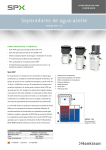
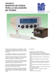
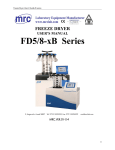
USER’S MANUAL
Laboratory Freeze Dryer
CRYODOS
CRYODOS_I_rev0105US
Telstar Industrial, S.L.
Josep Tapiolas, 120
08226 TERRASSA (Spain)
Tel. +34 937 36 16 00
Fax: +34 937 85 93 42
[email protected]
www.etelstar.com
Page 2 of 20
INDEX
1.
GENERAL DETAILS _________________________________________________ 3
2.
DETAILS OF THE FREEZE DRYER ______________________________________ 4
2.1.
Aim of this manual_____________________________________________ 4
2.2.
Description ___________________________________________________ 4
2.3.
Application ___________________________________________________ 5
2.4.
Required services______________________________________________ 5
2.5.
Technical features _____________________________________________ 6
3.
TRANSPORT ______________________________________________________ 7
4.
CAUTIONS BEFORE START-UP________________________________________ 8
4.1.
Positioning ___________________________________________________ 8
4.2.
Electrical connection ___________________________________________ 8
4.3.
Vacuum Pump ________________________________________________ 8
4.4.
Ice condenser ________________________________________________ 9
4.5.
Refrigerating unit ______________________________________________ 10
4.6.
Lubrication ___________________________________________________ 10
4.7.
Connection of the vacuum pump discharge__________________________ 10
4.8.
Long storage / Periods of non-use_________________________________ 10
5.
WORKING PRINCIPLE ______________________________________________ 11
5.1.
Freezing _____________________________________________________ 11
5.2.
Freeze drying _________________________________________________ 11
5.3.
Air entering drying chamber at end of the process ____________________ 12
6.
ACCESSORIES ____________________________________________________ 13
7.
OPERATING INSTRUCTIONS _________________________________________ 14
7.1.
Previous operations before start-up _______________________________ 14
7.2.
Control panel _________________________________________________ 14
7.3.
Instructions for start-up ________________________________________ 14
7.4.
Stopping the freeze dryer _______________________________________ 15
7.5.
Remarks on equipment operation _________________________________ 15
7.6.
Alarms ______________________________________________________ 16
7.6.1. Vacuum system alarm __________________________________________16
7.6.2. Vacuum probe alarm ___________________________________________17
7.6.3. Temperature probe alarm _______________________________________17
8.
ATTACHED _______________________________________________________ 18
8.1.
Working principle ______________________________________________ 18
8.2.
Guarantee certificate ___________________________________________ 19
8.3.
CE Certificate _________________________________________________ 20
Page 3 of 20
1. GENERAL DETAILS
This Operation Manual is valid for laboratory Freeze dryer models:
CRYODOS -50
CRYODOS -80
WARNING
•
It is mandatory to read and fully understand this manual before using the unit.
•
All safety instructions contained herein must be respected.
•
Before carrying out any maintenance work on the equipment, it must be disconnected
from the energy source.
•
Use or application of the equipment that does not conform to the recommendations in
this manual may cause danger and lead to the loss of the manufacturer’s guarantee.
MANUFACTURER:
TELSTAR INDUSTRIAL, S.L.
Josep Tapiolas, 120
08226 – TERRASSA (BARCELONA)
Telf. +34-93-736-16-00
Fax. +34-93-785-93-42
Web: www.etelstar.com
E-mail: [email protected]
Page 4 of 20
2. DETAILS OF THE FREEZE DRYER
2.1.
AIM OF THIS MANUAL
The main aim of this manual is to give the user guidelines for the handling and operation of
the TELSTAR CRYODOS –50 and CRYODOS –80.
2.2.
DESCRIPTION
The CRYODOS freeze dryer in a compact desktop version. The basic unit comprises a metal
cabinet, with a door at the back, which gives access to the inside for maintenance of all the
components. The vacuum pump is delivered separately from the unit
Cryodos components
•
One two-stage vacuum pump provided with Gas-Ballast. It holds inside a closing valve
which, when the pump stops, cuts the pump off from the freeze dryer unit and keeps it
under vacuum, while atmospheric pressure is re-established inside the pump, so that the
oil cannot flow back. It also has an exhaust filter.
•
One cooling system, cooling the condenser coil down to working temperature. The
condensation surface is designed to a size that ensures condensation of the vapour given
off by the product being freeze dried, preventing it from reaching the vacuum pump.
-
CRYODOS –50: one air condensing one-stage hermetic compressor.
-
CRYODOS –80: two air condensing one-stage hermetic compressors.
At the top, there is a stainless steel cylinder with 8 3/4” (18.7 mm) cocks and key. The
cylinder has a top cover made of a transparent acrylic material to enable inspection of the
condenser during the process. Each of the 8 cocks is equipped with its 3-way valve providing
cutting off and re-establishing atmospheric pressure in each individual vial. These enable
emery ground vial mouths to be connected with the tapering adapter they hold. (Outside
diameter, 29-32 mm – Inside diameter, 18 mm). Tubes and vials can be inserted directly
when this adapter is removed.
On the front, there is the control panel composed of a LCD alphanumeric viewer showing the
freeze-drying cycle menu. During the whole process, a screen with the condenser
temperature and vacuum value will appear, inserting every 3 seconds another that shows
the process time.
1
8
7
2
6
3
5
4
7
Page 5 of 20
1.- Condenser with 8 cocks
5.- Electrical connection
2.- LCD alphanumeric viewer
6.- Main switch
3.- Pressing buttons panel
7.- Vacuum pump
4.- Draining pipe
2.3.
APPLICATION
Using the various operative systems that make up the unit, and the possibility of connecting
several accessories, this freeze-dryer can be used for freeze drying in flasks, vials and
bottles or in bulk.
WARNING
•
Under no circumstances may the unit be used with corrosive, inflammable or explosive
gases.
•
In the event of freeze drying product containing corrosive or explosive solvent, please
contact the Technical Service, with a view to taking the specific preventive
measurements for the product in question.
2.4.
REQUIRED SERVICES
Power supply: 230 V single-phase + earth, 50 Hz / 230 V single-phase + earth, 60 Hz.
Power capacity installed: 1 kW for the CRYODOS –50 and 1,5 kW for the CRYODOS –80.
Consumption (Amps): 5,5 A for the CRYODOS –50 and 8,5 A for the CRYODOS –80.
Maximum working room temperature: +30ºC.
Page 6 of 20
2.5.
TECHNICAL FEATURES
VACUUM PUMP
CRYODOS –50
CRYODOS –80
50 Hz / 60 Hz
50 Hz / 60 Hz
Model
VARIAN DS 102
Dimensions
LxWxH
Weight
Kg.
Suction flow
3
22
m /h
Motor velocity
Electric consumption
Oil
430 x 132 x 212
Load capacity
5/6
r.p.m.
1500 / 1800
kW
0,45 / 0,55
Litres
0,5
Type
AV-30
ICE CONDENSER
Condensing surface
m2
0,136
0,136
Final temperature
ºC
-50
-80
kg.
4 (1,5 kg/24 h)
4 (4 kg/24 h)
Ice capacity
Condenser unit material
AISI – 316L
REFRIGERATING UNIT
Nr. of compressors
1
Hermetic type
2
Single-stage compressor
Refrigerating power
W
Refrigerant free of CFCs
450
900
R-404a
R-404a / R-23
Assembly refrigeration
By air circulation
UNIT
Electrical connection
V/ph/hz
Power capacity installed (unloaded)
kW
Vacuum at the pump inlet
mbar
Process vacuum
mbar
230/1/50
230/1/50
230/1/60
230/1/60
1
1,5
5 x 10⁻³
5 x 10⁻³
4 x 10⁻²
Condenser at –45ºC (CRYODOS -50)
1 x 10⁻³
Condenser at –75ºC (CRYODOS -80)
With room temperature not higher than +21ºC
Dimensions
High
mm
700
700
Width
mm
660
660
Depth
mm
730
730
Vacuum gauge
DIGITAL
DIGITAL
PT100 Temperature probe
DIGITAL
DIGITAL
60
90
Weight
Kg.
Page 7 of 20
3. TRANSPORT
The freeze-dryer is supplied as an individual package and in a suitable way to prevent it from being
damaged, during transportation.
With the freeze-dryer is supplied the vacuum pump separately crated, including technical
documentation and 1-litre bottle of oil. A tin of silicone oil is also supplied, for proper condenser
seals maintenance.
When unpacking the freeze-dryer, check if the supply includes optional accessories, each of which
would be separately packed to ensure suitable protection.
This manual is also included.
Page 8 of 20
4. CAUTIONS BEFORE START-UP
For a correct start-up procedure, the following instructions must be followed step by step.
4.1.
POSITIONING
The unit may be placed directly on a table if the surface is perfectly smooth and horizontal. The
base unit must be firmly settled to prevent vibration.
4.2.
ELECTRICAL CONNECTION
a) Connect the electrical cable of the unit to the power supply.
b) Check that the supply voltage is the correct one for the unit.
c)
The connecting cable is supplied with European plug.
WARNING
•
Before switching the freeze dryer on, check that the supply voltage is the same as that
mentioned on the specification plate.
•
Whenever there is a power cut or the supply fails for a long period, stop the Freeze
Dryer.
•
Installation in the place where the Freeze-Dryer is connected must comply with curent
safety regulations according to each country.
4.3.
VACUUM PUMP
Steps to follow in order to assembly the filter and the gas-ballast. This operation must be
carried out before the start-up of the vacuum pump.
1.
Connect the oil return filter to the vacuum pump by means of the centering ring and the clamp
to the DN25 connection
2.
Take out the screw and a oil return connection washer.
Filter
Screw
Washer
Screw
Gas-ballast
assembly
Top
washer
Clamp
Centering
ring
Inferior
washer
Page 9 of 20
3.
Insert the gas-ballast assembly to the screw and thread to the oil return connection.
Filter
Gas-ballast assembly
Screw
Elbow racord
Top washer
Inferior washer
Black pipe
4.
Connect the black pipe to the elbow racord placed in the connection filter base.
Pour new oil into the filling hole. Verify the level. Vacuum pump oil capacity: 0,5 litres (see
paragraph 2.1.3. maintenance manual).
It is recommended to open ¼ the gas ballast during the lyophilisation cycle in order to
prevent product vapours not to sublimate in the condenser. If this occurs, the vacuum pump
oil can contaminate
The vacuum pump is equipped with an exhaust filter, which job is to retain oils vapours.
The electrical connection of the vacuum pump has to be connected to the base placed in the
backside of the unit. Furthermore, the vacuum pump admission has to be connected to the
base unit through the supplied pipe.
4.4.
ICE CONDENSER
Before each operation, open the condenser water drain valve to ensure that the condensed
ice from the previous operation has been totally removed. If any water remains in the
condenser or drainpipe, it will freeze as a result of the vacuum, thus possibly compromising
work conditions.
Page 10 of 20
4.5.
REFRIGERATING UNIT
In order to ensure that the refrigerating unit works properly (refrigeration via forced air
circulation by means of a fan), all vents must be separated, minimum 20 cms. away from
other equipment or the wall.
4.6.
LUBRICATION
Slightly grease the airtight seals with the silicone grease. The contact surfaces should always
be kept cleaned and greased. Avoid dirtiness accumulation.
4.7.
CONNECTION OF THE VACUUM PUMP DISCHARGE
In the event that smoke from the vacuum pump is ducted outside, connect this tube to the
vacuum unit discharge, avoiding the installed filter.
4.8.
LONG STORAGE / PERIODS OF NON-USE
In the event that the freeze-dryer is placed in storage for a long time, the vacuum pump oil
must be changed to ensure that there is no corrosive waste that could damage it. Disconnect
the unit from the electricity supply. Clean the inside of the chamber, check that the
condenser has been completely emptied and lubricate the chamber and the condenser’s
gaskets.
Page 11 of 20
5. WORKING PRINCIPLE
5.1.
FREEZING
Products must be frozen before they are freeze-dried. The layer of product should be as thin
as possible (recommended inferior than 20 mm.). The length the freeze drying process
depends essentially on this height and the solid composition of the product. Fully
recommended are: even loading of the freeze dryer and equal heights in different containers
of product to dry. For the same reason, a mixture of products to dry should be avoided.
Freezing temperature is proportionate to product solidifying point. Freezing speed influences
the size of the crystals and, consequently, sublimation speed. Therefore, the most suitable
freezing parameters for each product must be determined. It is advisable to freeze products
at a temperature below -20°C for a period of between 3 and 4 hours.
5.2.
FREEZE DRYING
When the condenser reaches the programmed temperature and the vacuum pump is running, the
bottles or flasks with the frozen product are now connected to the condenser cylinder valves. Open
the valves so that the vacuum is produced in the container and product sublimation starts. As soon
as all the flasks have been connected and valves opened, there should be a vacuum of less than 10
mbar in 4 minutes; otherwise, the pump will stop, appearing the alarm of the vacuum system. If
this happens, check the valve-to-bottle connections for leaking. To continue with the process, press
the ENTER key.
When wishing to connect the flask when the freeze drying process has begun, proceed as below:
1.
2.
3.
4.
Connect the new flask and open this valve.
Wait for a while until a vacuum is recovered in the unit.
Connect the next flask.
When all the flasks have been connected, let the equipment run until the product has
been totally dried out.
If exterior heating has to be applied to the product while it is dried out to speed up the drying
process, the heating source should be at the right distance to apply the radiation heat that the
product requires. Heat from hot air directed directly onto the flasks may also be used.
At the beginning of the process, a layer of ice will form on the outside wall of the flask and this will
gradually disappear as drying out continues. Total disappearance of product ice is indicated when
the flask is at ambient temperature showing that the process has finished. When it has finished,
the appropriate manifold cocks are closed and air enters in the flask or flasks, so they can be
removed.
CONNECTING VALVE
Air inlet to flask
Vacuum to flask
Page 12 of 20
The length of the main drying process during freeze drying, depends essentially on:
•
•
•
•
•
•
•
The heating temperature that can be applied to product (outside the equipment).
The maximum heating temperature accepted by the product.
The final degree of humidity desired.
The percentage of solid material in the product.
The vacuum level obtained.
The total amount of product to be dried each time.
Condenser temperature.
5.3.
AIR ENTERING DRYING CHAMBER AT END OF THE PROCESS
Stop the process by pressing the ON/OFF key, which stops the pump and cooling unit and opens to
let air in through some of the taps. Place a recipe at the end of the draining tube and remove the
stopper. De-freezing can be sped up by applying hot air to the condenser coil. In any case, it is
advisable to remove the cylinder with the valves to accelerate coil ice de-freezing.
Before starting a new process, ensure that the condenser is totally defrost, there are no remains of
water in the drainpipe and that the valve is once again closed.
Page 13 of 20
6. ACCESSORIES
1- Stoppering chamber. Ref. 7801
Glass cylindrical chamber (Ø 200 mm.) with 3 non thermostatized shelves and manual vial closing
device. Includes 3 trays (for vials and serum).
2- Chamber. Ref. 8956
Glass cylindrical chamber (Ø 200 mm.) with 3 shelves and 3 trays (for vials, serum bottles and raw
material).
3- 8 port manifold. Ref. 70205
Including 8 rubber three way valves CN29/32 for flasks.
4- 40 port manifold. Ref. 7917
Manifold with 40 ports for tubes of 13 mm. Ø. REMARK: To install this manifold is necessary to
install the adapter plate for manifolds.
5- Adapter plate for manifold. Ref. 7820
Adapter to place manifolds with connection DN-50.
Page 14 of 20
7. OPERATING INSTRUCTIONS
7.1.
•
•
•
PREVIOUS OPERATIONS BEFORE START-UP
Check that all the water remains from de-freezing during the previous operation has been
removed by opening the draining valve. Close again.
Check that the condenser transparent cover is on.
Check that the all the cocks of the chamber are turned off.
7.2.
CONTROL PANEL
7.3.
INSTRUCTIONS FOR START-UP
To start the equipment, proceed as follows:
Set the switch on placed in the back side, just above the electric inlet plug to position I.
The following screen will appear:
CRYODOS
V 3.1 -50
TELSTAR ( c )
Fig. 1
After a few seconds the main screen will show:
SYSTEM READY
Press ON/OFF key and the screen will show:
Fig. 2
VAC.:
0.000 mBar
TEMP.:
-000.0 ºC
Fig. 3
The vacuum level inside the chamber and temperature in the condenser will appear.
Page 15 of 20
At this point, the following process automatically begins:
•
•
•
The cooling system starts (compressor 1).
In the CRYODOS –80, compressor 2 starts 4 minutes after compressor 1 has already started.
When the condenser reaches a programmed temperature (T), the vacuum pump automatically
starts.
T=-30ºC in the CRYODOS-50
T=-45ºC in the CRYODOS-80
REMARK: These pump starting Temperature Points are set and cannot be modified by the user.
Every 3 seconds Fig. 3 will be merge with Fig. 4.
COOL + VACUUM
TIME:
00:00:00
Fig. 4
7.4.
STOPPING THE FREEZE DRYER
Both models, when the freeze drying process ends, the equipment is stopped by pressing the
ON/OFF key. Compressor 1 will continue running for 2 minutes to collect the system fluid
refrigerant.
Accidental freeze dryer stopping.
If there is in the CRYODOS –50 an accidental stop, disconnection or power cut, the freeze dryer
stops and the vacuum in the chamber is maintained. Once the current is re-established, the
process continues working at the same conditions before the stop.
If it happens in the CRYODOS –80 and once the current is re-established, compressor 2 will run
after 4 minutes of the start-up.
7.5.
REMARKS ON EQUIPMENT OPERATION
Auxiliary screens. There are four auxiliary time counters viewing screens, for: compressor 1,
compressor 2 (CRYODOS –80 only), vacuum pump and language selection. To accede to the
auxiliary screens, simply press the UP/DOPWN keys one after the other being the freeze dryer at
rest, before pressing the ON/OFF key, so that “SYSTEM READY” is shown.
If there is a delay of more than 5 seconds in pressing the UP/DOWN keys on any of these screens,
the program automatically goes back to the main screen.
HOUR COUNTER
PUMP
00150 H
Fig. 5
HOUR COUNTER
COMP E2
Fig. 6
00070 H
Page 16 of 20
HOUR COUNTER
COMP E1
00080 H
Fig. 7
SELECT LANGUAGE
ENGLISH
Fig. 8
Language change
This option allows changing the screen language. There are 4 possibilities: Spanish, English, French
and German. By means of the ENTER key, languages will change. To fix one, press the UP/DOWN
keys.
SELECT LANGUAGE
English
SELECCIÓN IDIOMA
Español
SELECTION LANGUE
Français
SPRACHWAHL
Deutsch
7.6.
7.6.1.
ALARMS
VACUUM SYSTEM ALARM
If, when the vacuum pump is running, the vacuum level falls below 10 mbar in less then 4
minutes, the pump is stopped and the following message appears:
ALARM
[< -]
VACUUM SYSTEM
Fig. 9
Check all seals. Verify that valves and drain are closed.
Page 17 of 20
Once the leak has been found the message will disappear by pressing the ENTER key. The vacuum
pump will run again.
If the alarm does not disappear, contact the Technical Service Dept.
7.6.2.
VACUUM PROBE ALARM
If the vacuum reading falls below 1x10⁻³ mbar, this shows that the vacuum gauge is broken or
disconnected. The following message will appear:
ALARM
[< -]
VACUUM PROBE
Fig. 10
Review the probe and replace it in case is broken. Once it is verified, connect again by pressing the
ENTER key.
7.6.3.
TEMPERATURE PROBE ALARM
If the temperature probe is broken or disconnected , the following message will appear:
ALARM
[< -]
TEMP PROBE
Fig. 11
Review the probe and replace it in case is broken. Once it is verified, connect again by pressing the
ENTER key.
Page 18 of 20
8. ATTACHED
8.1.
WORKING PRINCIPLE
CRYODOS V3.1 -50
TELSTAR (c)
VAC:
TEMP:
0.010 mBar
-045.0ºC
ON/OFF
SYSTEM READY
TECHNICAL ASISTANCE
PROGRAM
ALARMS
3 Seg.
COOL + VACUUM
ON
TIME:
11:23:45
HOUR
PUMP
COUNTER
00150 H
ALARM
[<-]
VACUUM SYSTEM
COOL
OFF
ON/OFF
COOL
TEMP:
HOUR
COMP E1
COUNTER
00160 H
ALARM
[<-]
VACUUM PROBE
PUMP
OFF
ON/OFF
PUMP
VAC:
HOUR
COMP E2
COUNTER
00099 H
ALARM
TEMP
HOUR
COMP
COUNTER
00160 H
ENTER
E1
RESET ?
COMP
E1
[<-]
00160 H
HOUR
COMP
COUNTER
00160 H
ENTER
E2
RESET ?
COMP
E2
[<-]
00099 H
COUNTER
00160 H
ENTER
RESET ?
PUMP
[<-]
00150 H
SELECT
LANGUAGE
English
[<-]
PROBE
HOUR
PUMP
CRYODOS V3.1
ON
-091.0ºC
ON
0.010 mBar
Page 19 of 20
8.2.
GUARANTEE CERTIFICATE
TELSTAR INDUSTRIAL, S.L. guarantees the replacement FREE of CHARGE of all the pieces suffering
breakdown in the period of ONE YEAR, starting in the date of the expedition of the equipment.
The replacement of the pieces in guarantee can not in any case extend or modify the date of it.
TELSTAR INDUSTRIAL, S.L. will send in carriage forward and FREE of CHARGE the pieces to be
replaced, against the reception of the defective pieces. The necessary work to be done for its
substitution will be paid by the customer.
If the substitution of the pieces would take place in TELSTAR INDUSTRIAL, S.L. facilities, the client
will pay the transport of the unit.
This equipment has undergone satisfactorily all the tests and revisions. Therefore, any damage
caused by transport or wrong installation is excluded of this guarantee.
This guarantee does not include any of the fungible materials comprised in the equipment, such as
filters, fluids, filaments, etc.
The inappropriate use of this equipment provokes the guarantee to be void. This involves the
exclusion of any liability in concept of indemnity for eventual direct or indirect damages of any
nature, either material or personal.
Likewise, this guarantee will be void if pieces other than the ones supplied by TELSTAR
INDUSTRIAL, S. L. are used for the repairing of the equipment.
NOTE. This guarantee is valid for all the equipment unless otherwise stated. In order to
obtain any information about this guarantee, please contact with our Quality Assurance
Department.
Page 20 of 20
8.3.
CE CERTIFICATE
DECLARACIÓN DE CONFORMIDAD
DECLARATION OF CONFORMITY
Este certificado se emite para el aparato eléctrico/ This certificate is issued for the electrical
apparatus:
LIOFILIZADORES DE LABORATORIO E INVESTIGACIÓN
LABORATORY AND RESEARCH FREEZE DRYERS
MODELOS/ MODELS: CRYODOS-50, CRYODOS-80
Fabricada y sometida a Certificación por TELSTAR INDUSTRIAL, S. L./ Manufactured and
submitted for Certification by TELSTAR INDUSTRIAL, S. L.
91/368/EEC y 93/68/EEC Directivas Seguridad en Máquinas/ Machinery Safety Directives.
Normativa respecto a la cual se declara conformidad/ Standard(s) to which conformity is
declared:
EN 292-1, EN 292-2, EN 294, EN 418, EN 349
73/23/EEC Directiva Seguridad Eléctrica/ Electrical Safety Directive.
Normativa respecto a la cual se declara conformidad/ Standard(s) to which conformity is
declared:
EN 61010-1 (Requisitos de seguridad de equipos eléctricos de medida, control y uso en
laboratorio/ Safety requirements for electrical equipment for measurement, control and
laboratory use).
Directiva 89/336/EEC Compatibilidad Electromagnética/ Electromagnetic Compatibility
Directive.
Normativa respecto a la cual se declara conformidad/ Standard(s) to which conformity is
declared:
EN 50082-1, EN 55022, EN 61000-3-2
El año de marcaje CE fue en 1997/ The CE marking was affixed in 1997.
Por la presente, TELSTAR INDUSTRIAL declara que el equipo arriba especificado cumple con
las Directivas y Normativas arriba mencionadas, siempre y cuando la instalación sea acorde a las
especificaciones del fabricante.
TELSTAR INDUSTRIAL hereby declares that the equipment specified above conforms to the
above Directives and Standards, when installed in accordance with the manufacturers
specifications.
Eva Perelló
Quality Assurance
Terrassa July 2005