1
Karel Skipala
Automatization of production processes, machine control modernization, production of
industrial electronics
http://www.skipala.cz
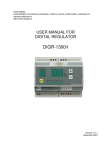
USER MANUAL FOR
DIGITAL REGULATOR
Version: 1.8
January 2008
1. Technical properties
Supply voltage
Maximal output current
Coverage
Working temperature
Power dissipation
Suppression of interference
Short circuit proof
Dimensions
Weight
230V AC/50Hz
8A
IP54
10-55oC (50-130°F)
10W
EN 55011/B
1.5kA
130x185x65 (WxHxD)
1.2kg
2. Generally
Regulator DIGR1200/E is intended to power regulation
of vibration feeders driven by electromagnetic coil.
Regulator’s main component is triac, which is switched
with phase shift. Regulator enables step setting of
frequency: 100Hz, 50Hz, 33Hz, 25Hz, and 20Hz. The
intensity of oscillations can be set from range 20–99%.
Function of regulator is programmed from control panel
by user. Regulator can be controlled from control panel
or by external analog or digital signals.
Small dimensions and effective user functions create
preconditions for using these regulators (working alone
or with superior system PLC) in most applications of
vibration feeders.
3. Before connection
Check up the regulator. Be sure it hasn’t been damaged
by transport. In the case of damage contact the
supplier.
If you see dewiness, wait for it’s evaporating.
4. Installation
Regulator can be mounted in horizontal or vertical
position with outlets down.
Drill holes to the main board, where the regulator
should be attached (pic.1), and make screw thread M4.
Attach the regulator with 4 screws M4x8.
2/12
pic.1 – holes for attaching
5. Connection
Only
persons
with
adequate
electrotechnical
qualification are allowed to connect the regulator.
Warning! Connect only when disconnected from power
network.
Unscrew four screws M3 attaching the cover (pic.2) and
remove it.
pic.2 – dismounting the cover
M3
M3
M3
M3
Terminal clamps are placed under this cover (pic.3).
3/12
pic.3 – terminal clamps
Make connection according to pic.4. If the supply
cable does not suit you, dismount it and connect clamps
L,N,PE with voltage 230V through cable H03VV-F3Cx1mm2 or
fungible. Connect coil of vibration feeder with clamps
U1,N1 and protective clamp marked by green-yellow
combination.
Connect
sensors
and
digital
or
analog
signals
according to demands of current application (pic.4). For
advanced
explanation
see
chapter
8
–
Functions
description. Sensors are powered by safely separate
voltage 24V DC, current drain of both sensors must not
exceed 50mA. Prefer sensors of PNP type (output signal
is attached to +24V). If you use sensors NPN, it’s
necessary to put a 3.3kΩ resistor between supply
clamp +24V and signal.
After your finishing the connection mount back the
cover and connect the regulator to the power network.
Status when the regulator is under voltage, but isn’t
switched-on, is signalised on display by turning on the
decimal point.
4/12
pic.4 – outer connection of regulator
L
N
PE
power supply
230V AC
U1
N1
vibration feeder
SQ1
max.
store
PNP
SQ2
min.
store
PNP
remote
control
signal
+24V
S
0V
1
2
3
+24V
S
0V
7
8
9
+24V
max 50mA
0V
4
5
6
+24V
0V
RP1
10
11
12
power
regulation 1-10k/N
+5V
560Ω
0-20mA
0V
11
12
0-10V
0V
11
12
5/12
6. Switching-on
There are three ways how to switch on the regulator:
I.Push the button on/off
.
For switching off push the button again.
II.Switching-on by remote control: Signal change on
clamp no.5 from 0V to +24V causes switching-on the
regulator. Signal change on clamp no.5 from +24V to
0V causes switching-off the regulator.
III.The regulator will automatically switch on after
connection of power supply. For this switching-on
set function no.5 to value 01. This type of
switching-on is possible only when the regulator is
controlled by superior controlling system. However
this setting is not suitable as START - STOP of
regulator because there is a min. 3s time-out
between switching-off and switching-on. If this
time-out is not kept the regulator may get blocked.
In that case you must do restart (see chapter 9).
Connect signal START-STOP with clamps no.2 (+24V)
and no.3 (0V) (see pic.4).
7. Setting
Switch on the regulator and press button
. The
number of function and its value will be shown on the
display. Set the number of required function by buttons
. Set the value of function by buttons
.
After setting all values press button
which will save
these values into memory. If you want to leave setting
without saving press button
. If you are not in
setting mode you can set only value of function no.0. –
required power. Regulator can’t save the change of value
when running. Save will be done after changing state to
STOP or when the regulator is switched off by button
on/off or by remote control signal. Warning! If the
regulator is RUN mode and you switch it off by
disconnecting it from power network, the value of
function no.0 won’t be saved into memory.
The meaning of functions and their values is described
in chapter 8 and in table pic.5.
6/12
8. Functions description
Function no.0 – required power
The regulator regulates power in maximal range 20-99%
with step 0.5%. Value 0.5% is expressed by turning on
the decimal point. The range of required power is
limited by values of function no.6 – minimal power
and no.7 – maximal power.
Function no.1 – sensors
Regulator can work according to the needs of concrete
application without sensors, with one sensor or with
two sensors. Signals from sensors set the regulator
to STOP or RUN mode. Status STOP is signalised by
turning on the decimal point at number showing the
number of function. The influence of sensors depends
on value of function no.1:
00- Sensors
are
not
connected.
The
feeder
is
constantly in RUN mode after switching-on.
01- One sensor is connected: SQ1 - maximal store. If
the sensor is active (there’s +24V on clamp no.2)
the feeder is in STOP mode. In other case the
feeder is in RUN mode. The change from STOP to
RUN mode and otherwise is done with a time-out
set by value of function no.2 and no.3 (see
down).
02- Two sensors are connected: SQ1 and SQ2. If sensor
SQ2 is not active (there’s 0V on clamp no.8)
regulator is in RUN mode. If both sensor SQ1 and
SQ2 are active (there’s +24V on clamps no.8 and
no.2) regulator is in STOP mode. The change from
STOP to RUN mode and otherwise is done with a
time-out set by value of function no.2 and no.3
(see down).
03- One sensor is connected: SQ1 - maximal store. Its
behaviour is inverse to value 01. If the sensor
is not active (there’s 0V on clamp no.2) the
feeder is in STOP mode. In other case the feeder
is in RUN mode. The change from STOP to RUN mode
and otherwise is done with a time-out set by
value of function no.2 and no.3 (see down). If
you start the regulator by superior controlling
7/12
system PLC, use this setting. Connect the START
signal with clamp no.2.
04- Two sensors are connected: SQ1 and SQ2. Their
behaviour is inverse to value 02. If sensor SQ2
is active (there’s +24V on clamp no.8) regulator
is in RUN mode. If both sensors (SQ1 and SQ2) are
not active (there’s 0V on clamps no.8 and no.2)
regulator is in STOP mode. The change from STOP
to RUN mode and otherwise is done with a time-out
set by value of function no.2 and no.3 (see
down).
Function no.2 – time-out when changing to RUN mode
Regulator is in STOP or RUN mode according to the
information from sensors. The change from STOP to RUN
mode is done with a time-out. This time-out is
expressed by value 0 – 99 which means 0 – 9.9s.
Function no.3 – time-out when changing to STOP mode
Regulator is in STOP or RUN mode according to the
information from sensors. The change from RUN to STOP
mode is done with a time-out. This time-out is
expressed by value 0 – 99 which means 0 – 9.9s.
Function no.4 – regulation method
The value of function no.4 determines the way how the
required power is set.
.
00- Power is set by buttons
01- Power is set by voltage signal 0-5V on clamp
no.11. This setting is suitable for using the
potentiometer. Value of the potentiometer must be
from range 1-10kΩ.
02- Power is set by voltage signal 0-10V or by
current signal 0-20mA on clamp no.11. If you use
current signal it’s necessary to put a 560Ω
resistor between clamp no.11 and clamp no.12.
Function no.5 – automatic switching-on
00- Automatic switching-on is blocked
01- The regulator will be automatically switched on
after connection of supply voltage.
8/12
Function no.6 – minimal power
Low limit of regulation is set by value of this
function. Minimal value is 20, maximal value is 10
units lower than the value of maximal power (function
no.7).
Function no.7 – maximal power
High limit of regulation is set by value of this
function. Minimal value is 10 units higher than the
value of minimal power (function no.6), maximal value
is 99.
Function no.8 – oscillations frequency
The range for frequency of oscillations is 20-100Hz.
The gist of frequency change consists in skipping a
certain count of sinusoid half-waves of regulated
voltage. Its result is a discontinuous “jump” change.
The range of this function is 0 – 4 that means
frequency 100-20Hz (see table pic.5).
Function no.9 – run-up, run-out
In some cases it is desirable to run-up and run-out
the feeder continuously. You can set the speed of
run-up and run-out ramp by setting this value from
range 0-5. Value 5 means time 5s for run-up
from 0% to 100%.
9. Maintenance
Regulator doesn’t require any special maintenance. In
case of failure do not do any repairs and send the
regulator to the manufacturer. A permissible faint power
oscillation can occur when the regulator works. This is
caused by interference from supply network.
If the regulator doesn’t work properly you can do the
restart that sets all functions to default. To restart
the regulator disconnect it from power network, press
the button SET, connect the regulator to the power
network and finally release the SET button.
9/12
pic.5 – Functions table
function no.
0 power
1 sensors
2 RUN
time-out
3 STOP
time-out
4 control
value
20-99
00
01
02
03
04
00-99
00-99
00
01
02
5 switching-on
6 min. power
00
01
20-89
7 max. power
30-99
8 oscillations
frequency
00
01
02
03
04
0-5
9 run-up
description
required power (20-99%)
no sensors
one sensor, log.1 switches off
two sensors, log.1 switches off
one sensor, log.0 switches off
two sensors, log.0 switches off
time-out when switching from
status STOP to RUN (0 – 9.9s)
time-out when switching from
status RUN to STOP (0 – 9.9s)
power is set by control panel
power is set by potentiometer
RP1
power is set by signal 0-10V or
0-20mA
automatic switching-on blocked
automatic switching-on allowed
minimal power limitation
(20-89%)
maximal power limitation
(30-99%)
100 Hz
50 Hz
33 Hz
25 Hz
20 Hz
time of run-up and run-out ramp
(0–5s from 0% to 100%)
10/12
pic.6 – control panel description
Signalling
under voltage
status when
the regulator
is switched
off
Required
power, value
of function in
setting mode
0.5%
Value
increasing
Number of
function (shown
only in setting
mode)
Value
decreasing
Signalling
of STOP
status
ENTER –
saving set
values into
memory
SET – entry
to the
setting mode
Selection of
function in
setting mode
on/off
11/12
10. Manufacturer’s declaration
Manufacturer declares that the product corresponds to
all requirements consequent on decree of the government
no. 17/2003 Sb. and no. 18/2003 Sb. about technical
requirements on products in full wording. Ground for
this declaration is certificate of Electrotechnical
testing institute no.1060967.
This product is safe under condition of usual using
and conditions noticed in this manual.
11. Warranty
We provide you a 12 months warranty since the day of
sale.
Serial number:
Dealer:
Date of sale:
12. Manufacturer
Production and service by:
Karel Skipala
Rybník 162
560 02 Česká Třebová
Czech Republic
tel.: 00420 465 533 410
e-mail: [email protected]
http://www.skipala.cz
12/12