1
08/2000
New Multi-Body Module for GHS & GLM
08/2000
Bug Notices for version 7.00
08/2000
Model Converter Gets New Features
08/2000
Project Directory Management Tips
08/2000
BOOM Command Update
12/1995
Another Approach to the Weather CriterionAnother
12/1995
Creative System BBS
12/1995
Digitizing the Ship
12/1995
Version 6.40 Update
04/1995
GHS VERSION 6.3
04/1995
Grain ShiftingGrain
04/1995
How to get your GHS Upgrades
04/1995
New Companion Products
01/1994
Criterion Crisis #1
01/1994
Dear GHS, BHS and BHS/Yacht Users
01/1994
Is Software Reliable?
01/1994
The GHS (General HydroStatics) Family
01/1994
WHERE IS GHS HEADED?
01/1993
The New GHS Grounding Method
10/1992
GHS Development
04/1992
IN DEPTH by Phil ReedApril
04/1992
VIRUS ALERT
April 1992 IN DEPTH by Phil Reed
The GHS.LIB file is very useful for customizing GHS to meet your particular needs. The GHS.LIB
file is a library file that can be setup with MACROS and KEY commands to automate many of the
procedures that you use on a regular basis. For example, the library file can be setup to enter
Part Maker using a single function key.
When the GHS.LIB file exists in your GHS directory, the MACROS and KEY commands in the file
will automatically be loaded into GHS when the program is run. Once the macros have been
entered into GHS, they are available to be used either interactively or through run files until they
are cleared or rewritten. Key definitions are available until the individual key definitions are
rewritten or the command KEY OFF is issued.
Placing macros in your GHS.LIB file eliminates the need to type or copy them over and over
again for each vessel. This saves time and eliminates the chance of typographical errors. The
GHS.LIB file can be setup so that everyone in your office is using the same commands and
macros, thus standardizing both the calculations and the output of the reports issued from your
office.
The following is an example GHS.LIB file. The first set of macros are run using the
corresponding KEY commands which follow. For example, you can automatically enter Section
Editor by pressing F7; or you can bring up the menu system by pressing F6.
MESSAGE "Reading GHS Library File....
MACRO HELP
IF "%1"="" THEN HELP|EXIT
SHELL GHSHELP %1
/
MACRO INTACT
units lt
limit(*) off
limit title Intact Stability Criteria
limit gm upright > 0.49
limit RA at 30 or MAX > 0.66
limit absolute angle at MAX > 25
limit from area 0 to 30 > 10.3
limit from area 0 to 40 or FLD > 16.9
limit from area 30 to 40 or FLD > 5.6
limit absolute angle at RA0 > 60
/
MACRO OUTPUT
status summary /vol:ga /brief
status /noref /fsm
ghs
status crtpt
/
`Sets Intact Stability Criteria
`Macro to output status report
KEY F1 "HELP|.HELP " "HELP" `Prompts for GHSHELP
KEY F2 "DIR | EDIT " "EDIT" `Prompts to edit a file
KEY F3 "DIR | VIEW " "VIEW" `Prompts to view a file
KEY F4 "COMPONENT|"
`List components of geometry file
KEY F5 "LIST|" "MACROS"
`List current macros
KEY F6 "RUN MENU.LIB|" "MENU" `Run the menu system
KEY F7 "SE|" "SE"
`Enter Section Editor
KEY F8 "ENTER PM|" "PM"
`Enter Part Maker
KEY F9 "LOAD(*) EDIT|" "LE" `Enter Load Editor, if available
KEY F10 QUIT|
`Quit GHS and exits to DOS
KEY C-S SOLVE|
`Solves for equilibrium
KEY C-T STATUS|
`Shows status of current condition
KEY C-I .INTACT|
`Runs the macro INTACT
KEY C-O .OUTPUT|
`Runs the macro OUTPUT
KEY SHOW
The CTRL-S and CTRL-T key combinations will solve for equilibrium and show a status of the
condition respectively. Pressing the CTRL-I key combination will automatically run the Macro
INTACT and set the limits as defined in that macro. Pressing the CTRL-O key combination will
automatically run the Macro OUTPUT and produce the output as defined in that macro. These
macros can also be called from a run file just as if they were defined in the run file.
Creative Systems will be distributing a GHS.LIB file along with the new menu system described
earlier. The F6 key will be configured to invoke the menu system. You can modify this file, or
create your own GHS.LIB file, using your text editor. Add your own macros or setup the KEY
commands as desired. Details on the KEY command can be found in the GHS Command
Dictionary.
April 1992 VIRUS ALERT
While Creative Systems has never distributed a disk containing a virus, and has never had a
virus infect its computers, GHS developer Bill Plice keeps reminding his staff that virus vigilance
is essential:
"The virus problem has become so prevalent that we have to take it quite seriously. A virus is a
clever bit of programming which someone produces with the specific aim of harming or
inconveniencing others, and which has the ability to replicate itself. Remember that viruses
never happen spontaneously, and they are always programs. This means that only executable
files and the boot sector of a disk (which is a primitive form of an executable file) can host
viruses. The same pattern of bits which constitutes a virus would be harmless in a data file, as
long as it remains a data file. Once the computer's stream of execution leads it to the virus (the
pattern of bits being interpreted as instructions), then and only then does the virus have an
opportunity to insert itself into the system, thereafter to be executed on a regular basis.
We must develop an abhorrence for a floppy disk being left in the slot from which the computer
will try to boot when the power is turned on. NEVER leave a disk in the slot longer than is
necessary to copy files to or from it. If you follow this simple rule, you will have almost no chance
of getting a boot- sector virus. Since a momentary loss of power to the computer will cause it to
reboot, any disk which happens to be in drive A has a potential opportunity to spread a virus from
its boot sector. Some computers have a BIOS setup program which allows you to have the boot
sequence ignore the floppy drives altogether and boot only from the hard disk. If your computer
has this feature, by all means take advantage of it and get complete protection from boot-sector
viruses. Remember that disks from big-name vendors and even blank disks, if they have been
formatted, can contain a boot-sector virus.
If you buy a new computer, I recommend reformatting its hard disk and reinstalling DOS only
from a new package. Then install a virus-scanning program -- also only from a new package -which has the ability to identify known virus patterns ("signatures") in executable program files.
Beware of any program files which are not from new packages; and even then scan them for
viruses before executing them. Make sure that everyone using your computer understands and
follows these precautions; and keep those floppy drives out of reach of any visitor with a dubious
disk in his hand.
These measures are simple, but each time they are overlooked you have a potential for a virus
infection. If you are careful to observe them, you need have no fear of copying data files from
any source whatever, including bulletin boards. With caution, you can also take in new program
files from reputable sources. It is always a good idea to scan new programs for virus signatures
and to run a virus activity monitor at least for awhile after a new program is installed in case it
discharges a virus whose signature was unknown to the scanning program.
Unfortunately, it is virtually impossible for a virus-scanning program to determine whether a given
program is a Trojan Horse or contains a "bomb" before such a program actually does its evil
work; so anti-virus programs do not give protection against absolutely anything. (This is usually
not the same as an innocent program which has been infected by a virus.) Fortunately, it is
unlikely that such a program would exist in a commercial product, since it would be the result of
sabotage by someone on the development team."
March 1993 The New GHS Grounding Method
A new development in GHS (also available in BHS) is a novel method of modeling ground
reactions which
yields greater realism than has been possible in the past.
Theory
The method assumes that forces due to grounding are buoyancies applied at the points of
grounding. These
buoyancies are derived by treating the ground as a very dense liquid.
Consider a point on the vessel where there is a present or potential contact between the vessel
and the ground. This will be called a "grounding point". The surface of the ground near such a
point is set to a certain level relative to the surface of the waterplane. This represents the depth
of the water at the grounding point. When the vessel tries to sink into the ground, it receives a
large buoyant force at the grounding point which prevents it from penetrating very far into the
ground. Conversely, if the vessel is raised up (relative to the ground) so that the grounding point
is actually above the ground surface, the buoyant force due to the ground becomes zero.
Just as the buoyant parts of the vessel receive upward, buoyant forces from the water which
depend on the depth of immersion, so the grounding points receive upward buoyant forces which
depend on their depths of immersion into the ground.
Implementation
In applying this theory, GHS makes the assumption that the ground buoyancy vs. penetration
function always
has the form,
b = C * (d - d0)2 for d > d0
b=0
for d ó d0
Equation 1
where b is the buoyant force at the grounding point, d is the depth of the grounding point below
the waterplane, and d0 is the depth of the ground surface below the waterplane near that point.
Figure 1 depicts this function.
The constant C is chosen such that the buoyant force becomes sufficiently large to "stop" the
vessel so that it sinks not very far into the ground. Note that this is one of the simplest ways of
meeting the requirement that the grounding buoyancy respond sharply to the penetration. It is
not intended to model any other characteristic of the ground/vessel interaction. Unlike real
ground, this model springs back when the penetration is reduced: the same buoyancy appears
at the same penetration regardless of whether it is approached from a lesser or a greater
penetration.
Equation 1 also allows an effective "waterplane area" to be derived at a given penetration by
taking the first
derivative:
a * D = « C * (d - d0) for d > d0
a=0
for d ó d0
Equation 2
where D is the density of the water (weight per volume), and a is the effective waterplane area.
In this manner the total effective waterplane area, center and moments of inertia can be
calculated (assuming, for inertia purposes, that the grounding point is truly a point).
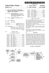
Grounding points are defined through an extension of the ADD command in a manner analogous
to the definition of weight items; viz. description, magnitude of force and location are given. The
simplest form is
ADD "description" b, l,t,v /GR
The /GR parameter indicates that a grounding point is being defined, rather than a fixed weight
item. The point (l,t,v) is the location of the grounding point (usually a point on the bottom of the
hull) where the coordinates are in the ship's coordinate system (grounding points are tied to the
vessel).
The b parameter is the magnitude of the buoyancy due to the grounding point at the present
water depth. Therefore, the waterplane must be set up to represent the grounded condition
before the ADD command is issued.
The above form of the command assumes that the grounding point is in contact with the ground.
If b = 0, then the depth to the ground is assumed to be exactly the same as the depth of the
grounding point. If b > 0, the depth of the grounding point is taken to be greater than the depth of
the ground; ie. enough greater to cause the force b to result from the penetration according to
equation 1. Values of b < 0 are not allowed.
It may seem that there is a difficulty with this method, since the value of b will seldom be
accurately unknown. However, due to firmness of the ground, an error in the initial specification
of b will usually not have significant consequences. Note that the b value given with the ADD
command is only at the present depth. As soon as the depth changes, the value of b
automatically changes also. Therefore, if the given value is too small, the vessel will settle down
to a slightly deeper draft. If the given value is too great it will rise up a bit until the ground reaction
makes up whatever buoyancy is missing from the displacement of water. But the change in draft
required will often be relatively small compared with the accuracy required in the analysis.
It is possible to define a grounding point which is, at the time of definition, not in contact with the
ground.
For example,
ADD "Port Bilge", 0, 12A, 35P, 1 /GR: -2.0
The "-2.0" is the penetration into the ground, but being negative it indicates a distance above the
ground surface. In other words, this grounding point will have to go 2.0 length units deeper
before it contacts the ground. Obviously, the b value must be zero when the penetration
parameter is negative.
Comparison with the Negative Weight Method
A traditional method of representing a ground reaction is to locate a "negative weight" at the point
of grounding (GHS is still able to apply this method also).
While the same ground reactions can be simulated with either method, the "negative weight"
method has limited usefulness for ascertaining stability when grounded. This is due to the
inability of the negative weights to respond to changes in the trim or heel of the vessel.
While the GM calculated with a negative weight is valid for single-point grounding where the point
of ground contact happens to be under the center of flotation, it is less valid in other cases. On
the other hand, the positive buoyancy method, by contributing to the waterplane properties,
results in a GM which is theoretically valid, though it may change very rapidly due the inherent
nonlinearity of the ground forces.
Another advantage of the new method is that the distribution of the ground reaction among
several grounding points is automatic.
January 1994 Criterion Crisis #1
GHS represents stability criteria by means of the LIMITS command. The RAH command can
then be used to determine whether a particular condition meets the applicable criterion. The
MAXVCG command can be used to calculate the maximum allowable VCG for any combination
of displacement and LCG (assuming TCG is zero). The MAXVCG command runs righting arm
curves for varying VCG's until it finds the highest VCG such that one of the defined limits is met
and the vessel still has positive stability.
LIMIT(1) ANGLE AT EQUILIBRIUM < 14.00 In an ideal situation, the MAXVCG
calculation solves for a VCG such that equilibrium occurs at exactly 14 degrees (RA1). In
calculating the maximum VCG, the MAXVCG command sets the VCG at its starting value and
solves for The problem occurs when GHS cannot get the Limit Margin to zero. For example,
there may be a condition where, as GHS lowers the VCG, equilibrium occurs before 14 degrees
and the Limit Margin is positive (RA4). If GHS raises the VCG to force equilibrium to occur at 14
degrees, the vessel no longer has positive stability (RA5). That is, the vessel runs out of stability
before the Limit Margin reaches zero. In this case, GHS cannot meet the requirement of the limit
.
The solution is to add another limit which requires positive stability. Such a limit
command is: LIMIT(2) AREA FROM EQUILIBRIUM TO RA0 > 0.00 This allows you to find the
largest possible VCG such that the vessel still has positive stability. LIMIT(2) will never be more
conservative than LIMIT(1) for those cases where GHS can satisfy LIMIT(1). It will only come
into play when LIMIT(1) cannot be met. Otherwise it will be ignored.
There are certain cases in which a maximum VCG cannot be determined. The most
common instance occurs when a heeling moment is applied to the vessel and the only limit is that
equilibrium occurs before a certain angle. This has been known to occur with the IMO Severe
Wind and Rolling criterion and the U.S. Navy Damage Stability criterion. The source of the
heeling moment may be due to wind, damage, lifting, towing, etc., but is not important. Assume
that the defined limit is as follows: equilibrium. If the angle of equilibrium occurs before 14
degrees (RA2), GHS raises the VCG and tries again. If equilibrium then occurs past 14 degrees
(RA3), GHS lowers the VCG. This iteration process continues until the Limit Margin is zero.
It could be argued that a vessel with a righting arm curve like RA4 is not a very safe
vessel. Theoretically, a mouse running from port to starboard would impose a sufficient heeling
moment to capsize it. Criteria of this type do not address this situation nor do they give you any
guidance on what to do if it occurs. Does the vessel in this condition pass the criterion? It
certainly has an equilibrium less that 14 degrees. How much area should be required between
equilibrium and the second intercept? Your professional judgement may lead you to require a
larger area. In any case, it is recommended that, for criterion such as this, you set the second
limit so that GHS can calculate a maximum allowable VCG for the given condition
Look for other Criterion Crisis articles in future editions of the Buoyancy News.
January 1994 Dear GHS, BHS and BHS/Yacht Users,
We are committed to providing our customers with the best and most current products, service
and support. We not only have a reputation to uphold, we feel that we have a moral obligation
to be here and do our best for each of our users. With each new software purchase we
provide 90 days of technical support at no charge. After that time, we offer each user the
opportunity to purchase an annual subscription. The charge for this subscription is based on
the type of program and the number of copies at the site. I thought that you would like to know
how your subscription dollars are utilized. We divide each subscription in half and apply one
half to program maintenance, development and enhancements. The other half funds your
unlimited technical support. With a current Maintenance/Support Subscription you receive, at
no additional charge, all program updates and access to any intermediate program bug fixes
and enhancements. We try to release at least one major program update each year. This
takes a monumental programming effort throughout the year to produce. When it has been
thoroughly tested and we are sure it is ready for release, we automatically send it to every user
who has a current subscription. If you allow your subscription to lapse, the cost to receive an
upgrade is 25% of your current program configuration. So you can see that the Maintenance
portion alone justifies the cost of an annual subscription. When it comes to Technical Support,
we have many subscribers who let us know that we provide some of the best they have ever
received. If after researching your documentation manual you are still encountering problems,
we expect you to fax or call us. We do our best to give you a straightforward and concise
answer to get you back to full productivity. We don't want you to struggle with something we
can help you with. But if you don't let us know that you are experiencing a problem, we can't
help you. We can offer this kind of excellent service because so many of our customers keep
their subscription current. This helps us to afford the technical staff to be here when you need
us. We want to express our appreciation to each of you who continue to support the
programming and technical expertise that it takes to keep GHS at the top of the list for quality
and user satisfaction. If you have not renewed your subscription, please call us so we can get
you current and also provide you with version 5.98, released last June. We are also looking
forward to the release of our next update during the first quarter of 1994. We are committed to
providing each of our customers with the best tools possible to meet the competitive needs of
the world marketplace. Your current subscription helps us to meet our goals and yours. If you
are still using a small, half-size documentation manual you are missing the BIG PICTURE.
Creative Systems produces full-sized manuals with tabulated section dividers and extensive,
detailed documentation on all aspects of GHS, BHS and BHS/Yacht. Each section covers its
topic thoroughly but in easy- to-understand, plain language. We issue a new and complete
manual with each new purchase, upgrade from another level of one of our programs, or a
conversion from an old AutoGHS program. We also sell manuals, at our cost, if you need an
additional or new manual. So if you are using outdated documentation and need to make the
most of your research time, call or fax us. We will be glad to get you the most current, easy-touse, thorough documentation available.
January 1994 WHERE IS GHS HEADED?
Over the past year, GHS has been under constant development to further improve its
reliability and increase its capability. This has resulted in a stream of fifteen interim versions
leading to a major upgrade which will be sent to all maintenance subscribers during the first
quarter of 1994.
What drives this development, and where is it headed? How is GHS faring against its
competition, and how is it responding to changes in the maritime and computing industries?
The technical requirements which affect GHS development can be boiled down to three
issues: 1) satisfying stability and strength regulations which prescribe certain methods of
analysis; 2) realistic simulation of loading, damage and grounding for salvage as well as for
certain operational applications; and 3) the integration of GHS into overall design and analysis
processes.
In all three of these areas expectations are escalating, presenting new challenges to GHS
which can only be met by extending its capabilities (which, in turn, will generate further
expectations on and on it goes).
Since the development of GHS is supported by its own sales, these technical expectations
cannot be satisfied without successful marketing.
Further, the usefulness of GHS often
depends on its not only being suitable in a technical sense, but also on its being recognized by
various regulatory authorities. The Politics of Stability Software
With the need to be recognized or approved by regulatory authorities, come several other
issues having little to do with technical merits: national loyalty, the favoring of internal products,
favored vendors, and the need of some agencies to be distinct from their competitors. Though
not without setbacks, GHS has been fortunate in this arena.
The best example is the Canadian Department of National Defence which bypassed its
domestic vendors and chose GHS for use in its offices and aboard its vessels. The Canadian
Coast Guard is presently following that lead. In the USA, the Navy has remained fragmented,
using hydrostatics programs from outside vendors while continuing development of its own
SHCP. GHS is used at several places within the Navy and the Military Sealift Command,
including installations aboard SWATH vessels. The US Coast Guard employs GHS at its
Marine Safety Center as well as in other places, but, like the Navy, also uses SHCP and other
programs.
Of the classification societies, ABS is the strong supporter of GHS. ABS personnel use it
in their offices worldwide and recommend it to their customers. Rinave in Portugal has also
adopted GHS. Other classification societies use and sometimes promote other software,
perhaps for competitive reasons.
Some governments and other regulators have official software approval processes which
usually involve high fees. To date, Creative Systems has not applied for many of these
approvals because of the high costs. However, it may become necessary to do so in the future,
which will, unfortunately, cause prices to rise and make further development more expensive (at
least for the approved versions).
Computer Technology & Fashions While GHS has a foot firmly planted in the maritime
industry, the other foot is in the fast-paced computer industry. Here we find fashion in full force
with the masses of computer users. Currently, mice and menus constitute the primary channel
through which people communicate with computers. But this paradigm will fall (though not
completely, for it has its place) when people eventually realize that the power in computers is
best utilized by devising recipes, not by picking from menus. Basically, a larger, more powerful
building block than the mouse click is needed
.
That Microsoft's Windows is perceived as a universal interface is a marketing success, not
a reflection of technical truth. Windows NT carries the universal interface idea even further, at
the price of an amazing complexity and an astonishing consumption of computer resources.
In the operating system battle, Unix seems to be losing for not having as much marketing
muscle behind it, for advertizing controls fashions. But lowly DOS, though old-fashioned, still
does most of the work and is the only current operating system which will still be available when
Windows becomes old-fashioned.
The major hardware race is between the "reduced-
instruction-set" (RISC) computers (often used in "workstations") and the "complex-instructionset" computers (CISC) such as are used in PCs. The trend is definitely toward CISC (even
RISCs are becoming more complex) since it puts more power (and therefore concentrates
activity) in a physically smaller space. This allows higher speed at lower cost.
In spite of all
the progress in the computer industry, software which runs on the PC and uses only DOS still
has the most secure future. Though the PC standard has always had its problems, it is and will
remain the best- supported and most economical computer for the foreseeable future.
For these reasons, GHS development remains tied primarily to the PC and DOS, though
other platforms may also be supported if sufficient demand and resources become available. It
is likely that a Windows version will be required before Windows looses its fashionable lead.
But the DOS version will certainly not be abandoned. Dividing the Pie
Although there are dozens of hydrostatics programs being used in the world, few have more
than a hundred users. In many countries, a national program is favored because it reflects local
language and custom, but it typically has little following outside of the country. Some large
design and construction systems contain hydrostatics modules, but the number of users is
limited by their high cost and the expensive hardware they require. Only a few (perhaps less
than eight) modern international hydrostatics programs have a significant number of users. Of
these, GHS and its derivatives BHS and BHS/Yacht appear to be leading, with over 440
separate users (not counting multiple copies in use by large firms and agencies). Although one
of Creative System's competitors seems to claim as many or more installations, being a former
GHS distributor they seem to be still including GHS in their figures. GHS at Sea
A growing
number of GHS users are realizing that they can provide an extra service for their clients by
installing a special form of GHS aboard their vessels. Called GLM (General Load Monitor), this
program has certain advantages over many of its competitors in the areas of efficiency,
accuracy, capability, and in connection with contingency planning and salvage operations.
Presently, over 30 ships are equipped with GLM including tankers, drilling ships, fishing vessels
and SWATHs. Many more installations are in the planning stages. Raw Reality Most stability
calculations in the office and even aboard ships are done according to somewhat artificial rules
laid down by regulators (often for archaic reasons having to do with the need to simplify hand
calculations). But when a salvage engineer looks at a stranded vessel, he is only concerned
about reality. The success of the actions he prescribes depends on how truly he is able to
simulate the situation beforehand.
Because GHS is simulation-oriented, it is a natural tool for salvage work. During the past
year, some of the world's best salvage engineers have used GHS in critical salvage operations
where it predicted results more accurately than other salvage software.
The "added buoyancy" grounding method pioneered in GHS has been successful where the
more limited and less realistic methods provided by competing software failed. The Future
Regulatory standards are changing, though slowly in many cases, and moving toward more
realism. While GHS has been ahead of its time for approaching hydrostatics on a realistic
basis, it must continue to develop in this direction. Developments which allow tanks to more
accurately simulate true behavior in conditions of partial flooding and with bulk cargos are in
progress.
When users see the benefits of the automation which GHS provides, they soon realize that
even more automation would be possible if they had more control over output formats. Plans
are in place for mechanisms which will provide this control. The goal is to allow a combination
of graphics with enhanced text such that more attractive, readable and compact reports can be
designed by the user.
Finally, more speed efficiency is in the works, both through making the fundamental
calculation processes more efficient and through extensions which help with the preparation of
input data.
While release dates for all of these improvements cannot be predicted with accuracy, the goals
are firm and progress toward them is steady.
April 1995 New Companion Products
A Special GLM for Tankers A GLM configuration for tankers has been developed by RINAVE C
& S in Protugal. It makes use of a proprietary module developed by RINAVE using the GHS
Programming Interface. In addition to the usual GLM onboard stability, longitudinal strength and
damage calculations, it offers a complete Ullage Report where product temperatures and ASTM
volume correction factors are used to compute product weights in air.
An LPG Tanker version is also available. Contact Mr. Elias Garcia, Tel: 351-1-301-6117 Fax:
351-1-301-6849. A GHS Windows Manager Visual Systems Workshop in Seattle, Washington
has released a Windows-based program called
Windows Manager for GHS (WMG) which runs along with GHS to help bridge the gap between
the command-oriented GHS and menu-oriented Windows. In addition to making GHS more
"Windows-friendly", WMG adds new capability such as a new geometry viewer which allows
views of the geometry to be cut and pasted to other applications such as word processors in
either wire-frame or rendered form. Contact Robert Horsefield, Tel: 206-285-2893.
GHS Geometry for AutoCad Tri-Coastal Marine in San Francisco, California has announced
an AutoCAD-based program AutoDock which links the design power of AutoCAD with the
abalysis power of GHS and other marine analysis software packages.
It will quickly generate intelligent 3D AutoCAD models to aid in visualization, creation of
presentation renderings, 3D layout, and detail design. Contact Keith Gallion, Tel: 415-6930853,
Fax:
415-693-0854.
April 1995 GHS VERSION 6.3
Creative Systems has added over 40 new features (compared to version 6.10) in its latest
version 6.3. Concentrated in the Main Program, they range from major improvements, to minor
convenience items. Nearly all of the new features also apply to BHS. Those that do not relate
to tanks also apply to BHS/Yacht.
Many of the new features are the direct result of ideas submitted by users. Others grew out of
experiences where Creative Systems supported users as they applied GHS in various types of
projects including salvage and shipboard applications.
In order to manage the large number of ideas and suggestions which it receives Creative
Systems maintains a list which is repeatedly analyzed, sifted and prioritized. From the ideas in
this list new features are designed and implemented in such a way that they harmonize with the
existing program. When a new feature is added, great care is taken to make it work well with
existing features, to complement as well as supplement the existing program.
Surprisingly, the addition of so many new features has not compromised the program's
performance. In fact it runs significantly faster and uses no more central memory. Version 6.3
fills gaps in the abilities of GHS and removes many minor inconveniences, making it a more
solid and useful tool than ever.
Formal Free Surface One of the major new features is the introduction of a formal freesurface- moment (FSM) attribute attached to each tank.
This replaces the old method which used aggregate "USERFSM" and "MAXFSM" values. The
new method allows you to assign formal FSM values to individual tanks where they are used
instead of true FSM values. This makes it easier to comply with regulations which call for the
treatment of free surface moments in a formalized way.
Having each tank carry its own formal FSM value removes the necessity of going through the
step of explicitly computing the "USERFSM" or "MAXFSM" with the STATUS command. Hence,
when working in the Load Editor, you get the same FSM value as when you run a righting arm
curve with RA /FSM. This makes it possible to find loading conditions using the Load Editor
which agree more closely in their stability limits with those which are computed from a rightingarm curve. For on-board use it allows better agreement with conditions shown in the vessel's
stability book.
Tank Pressure Balancing A new tank mode governs the level in the tank such that the
pressure inside the tank equals the pressure outside the tank at a given balancing point.
Inside pressure is determined by the density of the liquid and its depth at the balancing point.
Outside pressure is determined by the depth of the balancing point below the surface of the
water. If the top of the tank is sealed so that the pressure in the gas above the liquid can differ
from atmospheric pressure, that pressure difference is also taken into account. An important
application of this tank mode is in determining the outflow of oil from a damaged vessel.
Given an intact initial condition and the points of damage, the as-damaged condition and
amount of oil loss is easily and accurately determined. Smart Flooding Points Critical Points
have two new attributes. One is Flooding Status, the other is Symmetry Status. The Flooding
Status can be "Flooding", "Tight" or "Nonflooding". Hence you can use a critical point to model
a point of downflooding, a weathertight opening or some other point which does not relate to
flooding at all.
"Tight" critical points are considered to cause downflooding only when submerged at
equilibrium. For probabilistic damage you can attach a Tight or Flooding point to a division so
that it does not limit survivability when the division is already involved in the flooding
. The Symmetry Status allows a single Critical Point definition to serve as two points on
opposite sides of the vessel, or as one point, depending on the setting of the Symmetry
attribute.
Other New Features A new PERM command displays tank permeabilities and allows you to
change them from within the Main Program. Several new System Variables are available,
including HEEL, TRIM, AXIS, FP and AP.
Variable Arithmetic is now possible within the SET command. Operators include ADD,
SUBTRACT, MULTIPLY, DIVIDE, absolute value and trigonometry functions.
A new Status category, STATUS DELTA, produces a display showing the longitudinal and
transverse coordinates as well as the magnitude of the difference between weight and
displacement. HMMT TANK derives a heeling moment curve from the tanks through a given
range of angles. Useful for deriving water-on-deck heeling moments. Resetting the printer type
is made more convenient through the new PRINTER CONFIGURE command.
Tanks loads can now be specified directly in weight units both in the LOAD and the TC
command. And displacements can now be given instead of drafts for the GHS and HS
commands.
A new CHANGE command allows changing the name of a fixed-weight item
without reentering its numerical data or changing its position in the list. The VIEW command
now provides scrolling in either direction. It will also view the output file without needing to close
it first. Table headers now remain on the screen when a long table scrolls up.
There are, in addition to these highlights, more than 25 other enhancements.
April 1995 Grain Shifting
In order to handle more of the complexities involved in calculating the heeling moments
associated with the shifting of grain cargoes, a new GHS module has been developed. Called
GS (Grain Shift), this module is presently available as a menu-driven stand-alone program.
When grain is carried in general cargo vessels, imperfect loading or subsequent settling can
result in various pockets of void spaces between the surface of the grain and the undersides of
decks. These voids allow some shifting of the center of gravity of the cargo as the vessel heels.
The problem is to determine the amount of shift given the hold geometry. While some of these
cases can be modeled through the GROUP feature of the GHS Main Program, others involve
relationships between void spaces which are too complex for the tank-to-tank transfers available
through the GROUP command. The GS program takes another approach. Rather than
requiring a grain hold to be modeled as a collection of separate tanks, it provides a mechanism
whereby components within a tank can have individual surfaces. Thus a complex system of
voids can exist within a single tank part. An advantage of this approach is that the same hold
model can be used as a normal tank for damage analysis or liquid cargo. The GS program
provides screen and printer graphics, allowing the results of the grain shift to be more easily
checked. Creative Systems is offering copies of GS free of charge to current GHS users for
testing and evaluation purposes.
Creative Systems BBS
An "electronic bulletin board" system (BBS) is now on line 24 hours/day for the convenience of
GHS/BHS users who are subscribers to maintenance and support. The BBS contains three
areas: The Technical Support Forum contains answers to commonly-asked questions from
GHS/BHS users. You can browse the forum, reading or downloading these questions and
answers. You can also type in or upload your own questions. In the Library of Files you will find
a number of informational bulletins, Run Files, information about the latest versions, program
updates, special drivers, etc. The Private File Area is where you can upload and download files
in the course of your technical support communications with Creative Systems. The phone
number and other access information for the BBS is being sent to all maintenance/support
subscribers.
December 1995 Digitizing the Ship
Instruments combining laser distance measurement with precise azimuth and elevation angles
are finding increasing application in shipbuilding where accurate positioning is required.
Together with suitable software, these
instruments provide convenient and reliable
measurements of points in three- dimensional space resolved into a rectangular coordinate
system.
Through a software program developed at Creative Systems, you can use
measurements taken in this manner to produce mathematical hull models in the GHS format.
You might think of it as a three-dimensional digitizer big enough to handle a full-size ship.
When a lines drawing is unavailable or when you need an accurate as-built model of a hull, this
system could save days of work.
A GHS hull model consists of a series of two-dimensional cross sections:
planes which are parallel to one another. From a scale drawing of a "body plan" it is easy to
digitize and compile the two-dimensional sections into a GHS model: both model and drawing
use the same method of representing the three-dimensional object.
The problem with digitizing an actual hull is that there are no such sections marked. Marking
the sections or taking offsets at the required sections without markings imposes practical
difficulties. Other lines which follow more easily-marked features of the hull can theoretically be
used as the hull model, but how do you derive the needed sections from such lines?
The answer is the new software program called Shape Assembler which is able to take the
coordinates of the points which are easily obtained by surveying the hull and produce from them
the required cross sections. Given the abilities of Shape Assembler, you turn the problem of not
having section markings into an advantage.
Now you can concentrate on the true features of the hull rather than artificial cross sections.
Of course, digitizing in three dimensions and full scale is not as quick and easy as using a
digitizer tablet on a drawing.
Depending on the size of the vessel and the facilities available, it may take anywhere from one
to several minutes to obtain a single point. Obviously it is desirable to do the job with as few
points as possible. The way to economize on points is to construct lines. Well-placed lines can
represent the surface much more economically than random points. Almost all of the features of
the hull are conveniently represented as lines: the deck edge, chine, keel profile, etc. Before
the surveying session begins it is helpful to lay out the lines, either on the actual hull or on one
or more photographs. Most of the lines will go in a generally fore-and-aft direction. Each line
will be represented by a series of points.
Since Shape Assembler fits mathematical curves to represent the intervals between the points
on a line, it is able to do this with accuracy if the points are not too far apart for the degree of
curvature involved. Take the deck edge, for example. Assuming it is an unbroken sweep from
end-to-end, about 15 points will be sufficient. Where there is a knuckle or break of any kind,
the line should be broken into more than one line. In this manner, an entire single-chine hull
could be represented in as few as 60 points.
Transverse curvature, multiple chines, etc. will, of course, add to this number. T
he points which Shape Assembler receives from the survey must be in a rectangular coordinate
system; however, the system need not be aligned in a particular way with the vessel. Its origin
can be at the location of the transit, if desired, and its horizontal axes need not be aligned with
any axis of the vessel. Only the vertical axis should be reasonably close to the vertical axis of
the vessel.
Shape Assembler will accept data in the form of an ASCII file where each row on the file
represents a point from the survey. An additional file is required which you prepare after the
survey. This file specifies which points belong to which lines. The same point may be used by
more than one line, and not all points need be used. Points may be designated by name or by
row number.
Multiple surfaces can be handled, which is necessary for multihulls and whenever a prominent
appendage, such as a bilge keel, is not on the ship's centerline.
The output from Shape Assembler can be either a Geometry File or a three- dimensional DXF.
# $ K +
December 1995 Version 6.40 Update
GHS version 6.40 contains over 40 individual corrections and improvements relative to version
6.38. A significant savings in memory requirement was made in GHS by removing support for
computers which do not have math coprocessors. The math coprocessor is standard in all
Pentium class computers and most 486 class machines. Please contact Creative Systems if you
are running GHS on a computer which does not have a math coprocessor. (BHS and
BHS/Yacht do not require the math coprocessor.)
#
Version_6.40
Version 6.40
K
Version 6.40
+
BUO_NEW:0
$
# $ K +
December 1995 Another Approach to the Weather Criterion
The Weather Criterion (46 CFR 170.170) requires that the GM be at least as large as the wind
heeling arm divided by the tangent of the heel angle which reduces the freeboard by half (but not
more than 14ø). GHS can address an equivalent of this criterion through the use of certain
LIMIT commands as described in the "WEATHER" User Bulletin. Another approach is to
compute the required GM directly by making use of system variables. This can be done with
either GHS or BHS. A sample Run File implementing this method is available in the library of
the BBS (filename is REQGM170.RF).
#
Another
Another
K
Another
+
BUO_NEW:0
$
# $ K +
January 1994 The GHS (General HydroStatics) Family
In addition to GHS, Creative Systems produces and sells three other software products:
BHS, BHS/Yacht and GLM. These are all close relatives of GHS, and much that is said about
GHS applies to them as well. Two GHS packages (not distinct from GHS) also have their own
names: GHS/Salvage and GHS/Corporate. A complete GHS system actually encompases
every aspect of the other products. If you have GHS, you have it all. The BHS and GLM
products are designed to meet specific or less-demanding requirements. The Salvage and
Corporate packages are technically the same as GHS; only the licensing varies to meet special
needs. (Within each of the products and packages are one or more optional modules. Details
about specific modules are not covered in the present discussion.)
Here is a brief introduction to the members of the GHS family: BHS (Basic HydroStatics) is
very much like GHS. It lacks a few features which make stability analysis more automatic, but
otherwise covers the waterfront almost as well as GHS. It handles the same diversity of vessel
types, does damage as well as intact stability, and does all of the useful things with tanks that
GHS is known for. Some of the GHS model-building conveniences for handling appendages,
superstructure and wind planes are not present in BHS, but its hull- and tank-modeling tools are
the same as in GHS. BHS also omits tonnage calculations, and the Advanced Features module
is not available.
At a price which is roughly half that of GHS, BHS competes in a neighborhood where most of
the features it omits (and many of the features it has) are rarely found.
BHS/Yacht, in turn, looks very much like BHS. However, it does not go into the variabledisplacement aspects of hydrostatics since its intendeded use is for vessels which operate at
one displacement. It has none of the tank- related features of BHS, nor does it get involved with
damage stability. Nevertheless, it has a surprising number of features for an inexpensive
program.
Being of the same family means that many things are the same from program to program.
Geometry created with BHS or BHS/Yacht can be used by GHS and vice versa (though
BHS/Yacht ignores tanks). All of the facilities shared by the programs look and operate the
same from program to program. The advantage of this sameness is that you can upgrade from
one program to another without loosing your investment in data files and user skills. The price
you paid for the lesser program also becomes a credit toward your purchase of a more powerful
member of the family.
GLM (General Load Monitor) is a special form of GHS. Its primary application is aboard
vessels as a "trim and stability" calculator. GLM comes packaged with a special face, a menu
designed for the convenience of operating personnel who are only interested in evaluating the
stability of one particular vessel. GLM has access to the automatic stability-evaluation features
of GHS, but since it is not concerned with creating models, none of the modeling tools are
included. Each copy of GLM is also restricted to one particular vessel. These limitations in no
way limit its usefulness to the vessel operator, but they allow GLM to be priced well below most
of the competition
GHS/Salvage is a packaging of GHS with the selection of modules needed for salvage work.
In order to perform well as a salvor's tool, a hydrostatics program must be able to go well
beyond the traditional curves and tables used by naval architects. That GHS does this well is
regularly demonstrated by some of the world's leading salvage engineers.
GHS/Corporate is a complete GHS package including all optional modules and a special
licensing arrangement allowing its use in multiple locations within a company or governmental
organization.
#
The_GHS
The GHS
K
The GHS
+
BUO_NEW:0
$
# $ K +
October 1992 GHS Development
The development of the GHS system is driven by a number of forces. Primary among them are
the new technological developments in hardware and software from the computer industry, the
evolving regulatory requirements from the marine industry and, most important of all, the
requests from users. As the originator and sole developer of GHS, Creative Systems has
accumulated a great deal of information over the years about what is important to users.
This information has gone into making GHS what it is and continues to be the strongest force
driving GHS development. As long as the expectations and requirements of GHS users continue
to increase, GHS will continue to grow to meet these needs. But growth in software if not
carefully engineered can lead to conflicts of all sorts (such as incompatibilities with old data),
degraded performance and unwieldy complexity. This is where the value of Creative Systems'
20-year experience in hydrostatic program development most evident. New features are always
carefully integrated with the existing program so as to minimize any negative effects while
yielding the most widely useful enhancements.
This careful approach to development does not always result in the most speedy response to
the development forces but it ensures that GHS remains as reliable and stable as possible.
#
GHS_Development
GHS Development
K
GHS Development
+
BUO_NEW:0
$
# $ K +
January 1994 Is Software Reliable?
The mention of reliability in connection with computers brings to mind those frustrating
experiences when ... suddenly there's no response. There is nothing to do but face the death of
your session. You bury it with a Ctrl- Alt-Del. As computers have become commonplace it's
natural to think of them as appliances -- glorified typewriters into which you type information and
out of which you get reports. And this is actually true of computer hardware: it is an appliance.
For the most part it either works or it doesn't work. The distinction is usually obvious. But not
so with software -- especially "application" software, such as GHS, which applies the computer
to the real world outside of the computer. The array of ills to which software is susceptible might
surprise anyone who has been thinking of computers as appliances. Indeed, the reliability of
application software is a broader subject than might at first seem possible. While the seasoned
computer user will have some appreciation for the reliability problem, the prospective user -- the
buyer who is trying to sort out features in order to make an intelligent selection -- is most likely
not giving it nearly enough attention.
Briefly, here are a few important issues in software reliability which a purchaser would do well
to consider. - Basic Bugs Most widely recognized of software reliability problems is that
involving programming errors, commonly called "bugs".
A failure due to a bug is generally obvious, and would include anything from a complete "lockup" to a misspelled word in the output. It's probably true that no large computer program is
completely bug-free. But some are much closer than others. Given enough time and enough
use, the program should be cured of most of its bugs. The buyer might ask how long the
program has been in use and by how many users. Have the bugs been eliminated in updated
versions? - Correctness of Computations An enormous number of calculations are involved in
deriving one number of output such as a righting arm value, from the input data (the ship model
and its condition of loading, damage and miscellaneous external forces).
It is difficult to verify that everything is correctly computed in the program merely by observing
outputs resulting from certain inputs. A correct response to one set of inputs is no guarantee
that the response to another set will also be correct.
In the long run you have to trust the
software developer, but such trust need not be blind. Check the developer's reputation with
other users and other developers.
Abstractions and Assumptions Every software program which attempts to simulate reality is
inherently unreliable in a strict sense. The idea of any computer program truly predicting the
stability of a ship at sea is clearly unrealistic. Yet computer users tend to forget how wide the
gulf is which separates their printouts from the real world.
Unfortunately, some designers of computer software do not understand this as well as they
should. They unwittingly make their software unreliable by encouraging the user to ignore
important distinctions between reality and the simulation.
For example, they might allow the use of free surface moments in tanks to predict equilibrium
heel angle without mentioning the inaccuracy involved -- especially if their program is unable to
compute true CG shifts. Beware of application software which claims to be extremely easy to
use. Are the simplifications which lead to ease-of-use insulating the user from the
assumptions? Are its standard, cut-and-dried procedures so easily used that the user forgets
their limitations; or does the user find it just as easy to select the correct procedures? Readable Reports Another point at which errors occur is when output data is read, interpreted
and applied. This might be done by someone not involved in using the program, who may
#
Is_Software
Is Software
K
Is Software
+
BUO_NEW:0
$
therefore be less aware of the assumptions upon which the data is based. Software reliability
also depends on whether the reports are designed to reduce misinterpretation.
- Stability of the Source While most aspects of software reliability deal directly with
performance, this issue concerns the long-term value of the software investment. Stability of
the developer -- whether the program will still be supported and competitive in the future -affects reliability as an investment. Shifting from one hydrostatics/stability program to another
involves substantial training and data conversion costs which must be added to the cost of the
program itself.
Is GHS Reliable? Where does GHS stand on these reliability issues? Regarding bugs, thanks
to its constant use in many places over a period of several years, GHS has reached an
enviable degree of solid, bug-free maturity. GHS has a reputation for giving correct results.
When comparisons with the results from other programs show differences, the explanation
usually turns out to be that limitations in the methods employed by the other program produced
approximations or errors.
By design, GHS does not hide its assumptions. Neither does it present a standard approach to
solving problems in order to be easy to use. Rather it encourages the user to apply the most
appropriate methods to each analysis. It is typically easier to apply the procedures which lead
to the most accurate results than to use approximations. GHS reports include a mention of
units, environmental variables (such as wind, waves and water density) and pertinent
independent variables. If the exact condition of the vessel is not shown, enough information is
presented so that it is linked to the report which gives the details of the condition.
Creative Systems is a reliable self-sustaining, profitable company which has been in the same
business for over 21 years. The development and maintenance of GHS is its primary business.
It receives funding only from its customers through sales of GHS and related products and
services.
# $ K +
How to get your GHS Upgrades
All GHS, BHS and BHS/Yacht users who have current Maintenance/Support Subscriptions will
automatically receive upgrades at no additional charge. If you are not a Maintenance/Support
Subscriber, the upgrade to the current version is 25% of the new-copy price.
#
How_to
April 1995 How to get your GHS Upgrades
K
How to
+
BUO_NEW:0
$
New Multi-Body Module for GHS & GLM
Creative Systems, Inc. is announcing that its General HydroStatics (GHS) software can now
handle multiple floating bodies with points of contact between them. Ground contact can be
included simultaneously.
Applications include:
• detailed simulation of loading and unloading floating objects by partially submerging the
carrier;
• complex salvage procedure modeling;
• onboard load monitor for tug-barge units;
• ice breaker simulation;
• dry docking;
• articulated floating structures.
Equilibrium of the entire multi-body system is found automatically and the forces at the points of
contact are reported.
This new capability is available through an optional software module being called simply "MultiBody" or MB. It is tightly integrated with GHS so that the usual features of the program can be
used in conjunction with it.
The MB module allows GHS to model the interactions of multiple vessels in a wide variety of
configurations when latched together or resting on each other. It models each vessel in a
separate side-by-side session of GHS and quickly solves for simultaneous equilibrium whenever
anything in the system changes. For example, the effect of changing the load in a tank on one
vessel can be seen also in the draft, trim and heel of the vessel with which it is in contact as well
as in the contact force. The contact forces are automatically included in stability, longitudinal
strength and torque calculations.
For more details contact Creative Systems, Inc. at 360-385-6212 (phone), 360- 385-6213 (fax), or
[email protected] (e-mail).
Bug Notices for version 7.00
LIMIT RA command:
(a) LIMIT RA AT ang1 OR ang2
(b) LIMIT RA AT ang1 TO ang2
In GHS versions 6.74 through 7.02D the interpretation of these two commands was reversed. In
other words, the "OR" keyword behaved as the "TO" and vice versa. Please check any work that
you did with any version of GHS in this range and make sure that this LIMIT was not controlling
any cases.
As described in the GHS User's Manual, the value of the righting arm (RA) is taken at ang1
unless,
in form (a) ang2 is greater than ang1
in form (b) ang2 is less than ang1
in which case the RA value is to be taken at ang2.
Note: Since this bug can cause incorrect results in certain stability evaluations, a corrected
version, 7.04, is being issued to replace 7.00.
A bug involving the CRIT command has been found in GHS version 7.04J - 7.04V.
The CRIT command with the /SYMM parameter is not being properly recognized (it's actually
being interpreted the same as /FLD). It has been corrected in version 7.04W.
See the update history section of the Customer Support Center for the latest available beta
versions.
GHS 7.0 Shipments Completed
The GHS, BHS and BHS/Yacht version 7.0 update has been shipped to all users who are current
with their Maintenance/Support subscriptions.
Unfortunately, a bug has been discovered in GHS 7.00 affecting one stability criterion limit. See
Bug Notices, above.
A corrected version of GHS fixing this bug is available. Notices are being e-mailed or faxed to all
users who received a copy of GHS that was affected. The notice contains options for receiving an
update to version 7.04. If you have not received such a notice, please contact Creative Systems.
SUMARY OF NEW FEATURES
(since version 6.70)
A Windows 32-bit main program, report generator and print/plot utility are now included in
addition to their DOS-based counterparts so that we continue to be compatible with all PC
operating systems. When running under 32-bit operating systems (Windows 95, 98, NT, etc.) the
speed and capacity are much greater than in any previous release.
An entirely new SE program is included with this release. It also supplies the main-program
DISPLAY function. Please see the revised SE section in the manual for details.
Please refer to separate installation instructions. The files are compressed and require that the
installation program be run in order to decompress and copy them to the program directory.
The more significant improvements and bug fixes are listed below. Please see the manual
updates for complete descriptions of the new features.
Other Changes and Improvements
Flooded tanks now automatically assume the new density of the external environment when it is
changed (via the WATER command). Formerly the density assigned to flooded tanks only
changed in response to the TYPE and CONTENTS commands.
The actual volume in a tank when damaged or flooded can now be used to set the load when
changing the type to intact. This is accomplished by adding the parameter /HBL to the TYPE
INTACT command. The same operation can be performed in the Load Editor by entering "HBL"
rather than "INTACT" when changing the type of the tank.
The density of the water used in WDF tanks can now be specified independently of the external
water environment by means of an additional parameter on the WATER command: WATER
spgr1 /WDF: spgr2 where spgr1 sets the external water environment and spgr2 sets the density
used in WDF tanks.
A new Calibration Mode applies to tanks that have property tables augmenting the Shape in the
Geometry File. (Property tables can be added to a geometry file by menas of Model Converter.)
Initially, Calibration Mode is "off" for all tanks. It can be turned on for all tanks having property
tables or selected tanks through the TYPE CALIBRATE command. For example, TYPE (*)
CALIBRATE "turns on" Calibrate Mode for all tanks that have property tables. The former tank
type is not altered. For example, if the tank was FLOODED, it will remain so. Calibration Mode is
"turned off" when the tank type is set to anything else. For example, TYPE (*) INTACT makes all
tanks intact with Calibration Mode "off". When Calibration Mode is in effect for a tank, its name is
preceded with a "#" whenever its properties are shown, such as in the STATUS report. This is not
properly part of the tank's name, but it may be used in a TYPE command when the subject tanks
are in Calibration Mode. For example, TYPE (#*) INTACT restores only those tanks which are
presently in Calibration Mode to normal intact mode.
HMMT TANKS /CONST sets the heeling moment as a constant value derived from the present
transverse weight moment of all tanks.
New parameter on LOAD EDIT command: /API forces API units when in metric mode, replacing
KG/CM.
Load Editor now accepts "SEA" as a contents description for intact tanks, causing the contents to
become the same as the external water environment. This has the same effect as using "SEA" in
the CONTENTS command. (Subsequently changing the external water environment has no effect
on the contents of intact tanks.) Load Editor displays the contents as "SEA" unless the external
water environment becomes different, in which case it displays "SEA WATER".
GMT and roll period are no longer available in the Load Editor when the axis angle is not zero.
Formerly it was available but misleading because it was not for the rotated axis. The GHS/HS
commands now show drafts in feet and inches if they are given in that format;
e.g. 3'01, 3'02 ... 5'00 means every inch from 3 feet to 5 feet.
MAXVCG process - "Unverifiable LIMIT" error has been downgraded from fatal to warning.
A new parameter, "/LOOKUP", is available on the MAXVCG command which causes it to run in
"lookup mode" where it looks up maximum VCG values in the table already calculated in the
previous MAXVCG command (or composite of previous MAXVCG commands). An improvement
in the MAXVCG solving process results in faster convergence when some limits are insensitive to
the VCG.
Other improvements in the MAXVCG process: more tolerance of large trim angles; finds the
maximum VCG when the range of trim stability is narrow.
In the LIMIT command, a new keyword "PRE", standing for the pre-roll heel angle, is available.
This is the heel angle that exists just before the command HEEL=*-ROLL is issued.
In the HMMT command, a new parameter, /POSTROLL, is available. This causes the heeling
moment to be suspended until after the HEEL=*-ROLL command is issued.
A new LIMIT angle keyword "EQU0" refers to the equilibrium angle that would exist if there were
no external heeling or trimming moments.
In Limit reports, "Deck Immersion" is now expressed as "Deck/margin Immersion".
The RA command /STOP parameter is now active with /LIM.
A further refinement in the RA procedure enables it to return limit angles which fall into a
discontinuity. In all reports where the "with DAMAGE" phrase appeared with either FLOODED or
DAMAGED tank types, it now appears only when DAMAGED tank types are present. If
FLOODED tank types are present but no DAMAGED types, the phrase "with FLOODING"
appears. Likewise, the screen header now shows either DMGE or FLD in the main environment,
and DAMAGE or FLOOD in the Load Editor. The DECK type now causes "with WATER ON
DECK" to appear unless other tanks are DAMAGED.
In case the "with FLOODING" or "with DAMAGE" in table headers is objectionable, the GHS, RA,
CC, MAXVCG and DAMSTAB commands now allow a /BENIGN parameter to avoid having those
words appear.
New LS report format showing percentages and limits for shear and bending moment.
Activated with /LIM parameter on LS command.
There is now a capability for dual shear limits based on the sign of the bending moment. LSLIM
SHR now accepts the "l1 & l2" format as used with LSLIM MMT. However the signs on the l1 and
l2 values refer to the sign of the bending moment: negative values indicate the shear limit (for
both positive and negative shear) to be used where the bending moment is negative (sagging).
LS with frames now include the exact frame locations in the original load curve to ensure the test
possible accuracy at those points.
The LS command operates normally in the absence of a .FRA file when the /FRA parameter is
present.
Kilonewtons are now available as a units setting. UNITS KN sets the units used for weights and
forces to kilonewtons. This is applicable to LS reports and should not ordinarily be used for other
reports. It also affects the units for SMOD (M^3) and the stress and elasticity modulus
parameters on the LS command (megapascals = 1000 KN/M^2).
Bulkhead shear force correction is now available. A shear force correction factor is carried in the
geometry file in the part record, where it follows the sounding tube information (if any) and is
introduced by a line containing only "-1". If this factor is present, shear forces over the length of
the tank are modified by the addition of a linear function which is one-half of the original change in
shear over the length of the tank times the correction factor. This correction is applied
automatically unless a /NOCORrect parameter appears on the LS command. The correction
factor is calculated and added to the geometry file using Part Maker.
A new command, TORQUE, is included in the LS module. It produces a table and plot of twisting
torque due to differences in weight and buoyancy distributions.
DAMSTAB /SDIC now includes the revised Required SDI applying to vessels between 80 and
100 meters Ls (IMO Regulation 25-3 effective 7/98).
DAMSTAB /SDIP can now be used for the full (not simplified) IMO resolution A265(VIII).
DAMSTAB no longer stops with an error message when longitudinal instability is encountered.
WRITE (LOADS) now includes heel and trim angles for frozen tanks.
Reports can now be printed with boxes drawn around tables and headers.
RG.EXE is obsolete; its functions are now handled internally within GHS during REPORT, RG,or
PRINT command processing.
The PRINTER command now supports network printers (e.g. PRINTER \\server\printer), while
PRINTER ON uses printer port set in PRINTER CONFIGURE by default rather than LPT1.
Plots now use a default left margin of 0.5 inches instead of 0.25 inches, in order to allow space
for looseleaf binder punch holes and to avoid memory overflow problems on some old printers.
The REPORT and RG commands now have a new parameter /MARGIN to adjust this margin
manually.
The Report Generator was made tolerant to Cross Curve tables where data is missing in the flood
columns, and boxing performance was improved for large Cross Curve tables.
RG no longer waits before scrolling unless /WAIT parameter is used.
PRINT command recognizes /MARGIN and /WIDTH parameters same as REPORT and RG.
REPORT CLOSE in keyboard mode requires "Print report?" confirmation before printing; printing
occurs automatically in runfile mode. Likewise, when redefining the REPORT file, printing
requires confirmation in keyboard mode, but it is always suppressed in runfile mode.
PRINT /MARGIN has two different meanings. If a filename is given, /MARGIN parameter is a size
less than 1 inch (same as for REPORT and RG); otherwise, /MARGIN parameter is an integer
number of characters. PRINT CONFIGURE /16 causes causes PP instead of PP32 to be used for
printing. Vessel names appear boldface in the header of reports printed through PP32. REPORT
and RG have a new parameter /COUNT, which includes the total page count in the header (e.g.
"Page
1 of 10", "Page 2 of 10", etc.). DIR command now omits files ending in ".$$$" unless explicitly
specified. The configuration information is now stored is a special directory off the root of the
same drive where temporary files are stored. This allows the program directory to be made readonly if desired. SHELL command looks in the GHS program directory as well as the path. The
mouse can now be used to select a row and field in the Load Editor, select MENU lines and to
click the "SPACEBAR to continue". Commands and words from the screen can now be brought to
the command line at the present cursor position by clicking on them with the mouse. However, if
the mouse is dragged during clicking, then the selected text is instead made available for copying
to the clipboard by pressing Ctrl-C or choosing "Copy" after right-clicking. (32-bit mode only). The
GHSSHELL environment variable, if set, specifies the command processor and switches to
override normal shelling to auxiliary programs. The SHELL command has additional parameter
options for diagnostic purposes: (1) SHELL /V shell command - specified shell executes
command verbatim; (2) SHELL /VC [/K] command - default shell executes command verbatim; (3)
SHELL /VE [/K] command - CMD.EXE shell executes command verbatim. If /K present for (2) or
(3), command waits for EXIT before returning. If a geometry file exists in the key file directory
instead of the current directory, READ copies it into the current directory so it can be shared with
shelled programs like PM and SE. If the program starts in the key file directory and then does
CHDIR to another directory, READ can now find geometry files in the key file directory.
Multiple geometry files can now be listed in the READ command.
SCREEN MIN, SCREEN MAX, and SCREEN NORM commands minimize, maximize, and
restore the window in 32-bit mode.
General Load Monitor is now a separate program GLM.EXE, identified as GLM at the top of the
program, with a new Longitudinal Strength Graph display option not contained in GHS.
SE file [part[\component]] reads and edits the specified file and optional part. If file is not
specified, SE reads the current geometry file, and upon return the main program automatically
reads the last geometry file written by SE (if any).
The maximum allowed height of the wind pressure profile (WIND command) has been increased
from 100 to 200 meters. The maximum number of tank loading levels obtainable from the TC
command has been increased to 1001. However, plots will not be produced if the number of
levels exceeds 100. The TC report when using soundings in metric units shows millimeters for
soundings rather than centimeters as formerly.
The number of decimal places carried during variable calculations in the SET command was
increased to 5. The maximum number of macros in 32-bit mode has been raised to 200; the
maximum macros in 16-bit mode remains at 120. A new integer system variable DAMSTATE
contains 1 if there are any flooded- or damaged-type tanks; otherwise it contains 0. Recognition
of "hardware lock" dongles over a network is now possible.
BUG FIXES
A bug in the calculation of free surface moments for empty tanks in SPILLING mode was
corrected. The free surface moment obviously should be zero but it was showing up as a nonzero
number in the STATUS report.
WDF tanks in STATUS TANK:BRIEF were having their seawater represented twice. Also
STATUS WPL was showing WDF tanks even when empty or full.
Solving with DAMAGED-type tanks now avoids "negative waterplane" errors.
In some cases the HF termination angle in a LIMIT command was being interpreted as DI.
MAXVCG was not handling the direction of heel properly with very small but nonzero equilibrium
heel angles.
MAXVCG with varying ROLL (i.e. ROLL IMO) and relatively small heeling moments was
sometimes not converging. The result was VCGs which were obviously too low.
Long command lines (greater than 256 characters) were being truncated in some cases.
The Load Editor was not properly handling frozen tanks with sounding tubes: soundings were not
being correctly translated to loads, especially when the tank location was a great distance from
the origin in the presence of large trim.
Load Editor SOLVING is now more sensitive to small changes in loads.
Model Converter command lines longer than 80 characters were being truncated when specified
inside run files; this condition has been corrected.
The specific gravity table was not being properly reinitialized after a failed READ command.
Improved and corrected report formatting details. Corrected occasional appearance of extraneous
trailing characters when picking words from the screen with the arrow keys.
In the RA command with nonzero AXIS the floodpoint height was sometimes unreliable near the
downflooding angle.
When the RA curve is discontinuous due to a sudden trim shift or damaged tank flooding, the
second intercept was not being identified, causing limits referencing RA0 to be undefined.
Longitudinal Strength with large distributed weights in addition to light ship was sometimes
producing a "Weight Center Discrepancy" error.
DAMAGE type tanks were causing LS to abort with "PSI" error messages.
DAMSTAB was not progressing through all divisions when the divisions were not numbered
starting with 1.
DIVISION /FLD:n was changing the type of critical point n to FLOOD if it was TIGHT.
A READ command containing a path given at the PROJECT prompt is no longer mistaken for a
project directory specification.
Correction made to accept a colon or equal sign after the /PEN parameter on the GROUND
command. Before this correction it was shifting the first parameter after the /PEN to the second
parameter place.
Light ship weight curve terminating with a zero wt/length was giving zero weight.
ENTER command now correctly deletes temporary .RUN file even when multiple instances of
GHS are running on the same machine.
Picking items from the screen during an INPUT command sometimes failed to access columns
directly above the input field.
Corrected the tendency to miss slash parameters when not preceded by a space.
Model Converter Gets New Features
Although Model Converter has been packaged with all GHS systems sold in the last few years,
some GHS users whose original purchase preceded its availability have not been aware of the
many benefits it now provides. Even if you do have MC, you may wish to use this as a refresher
about recently- added features.
A host of recent enhancements have made Model Converter even more useful as a manipulator
of Geometry Files. Some of the things which MC now does are:
Adds and deletes stations at given locations. When it is necessary to enhance a model by adding
one or more stations at certain locations, MC makes it easy. Certain stations can likewise be
deleted. Features like these make it possible to completely automate the generation of a model
without the need for manual editing steps.
Marks the deck edge only between given longitudinal limits. Sometimes it is desirable to limit the
deck edge to avoid including hull features which are not part of the deck. MC makes it convenient
to do this without the need to edit the Geometry File directly.
Sets margin values. Margin values can now be set with MC, avoiding the need to use Part
Maker. This adds convenience when using MC to mark the deck edge.
Reorders the tanks to be in a specified sequence. Using a given list of tank names, MC will
reorder the tanks in a Geometry File to match the order in the list. This controls the order in which
tanks are presented in reports. Sets tank descriptions. Tank descriptions can be conveniently
added or replaced at the same time that their order is being rearranged. Fixes clockwise loops.
Various defects which prevent Geometry Files from being accepted by Part Maker can be
corrected using Model Converter. Small clockwise lobes are removed and stations which have
points running in the clockwise direction are corrected by reversing the sequence of the points.
Corrects shell thickness settings. Sometimes Geometry Files generated by non-GHS software
use the shell thickness fields for other purposes. MC provides a way for these to be conveniently
corrected. Deletes components. The removal of components such as hull appendages or
superstructure is facilitated by this feature which may be more convenient than using a Part
Maker.
Changes a component from being adding to being deducting. Changing the sense of a
component from positive to negative or vice versa is easy with Model Converter. Removes all
tanks or sails from a model. If tanks are not being used, a faster-running model can easily be
created.
Removes all but tanks from a model. A separate model to be used only for tank capacity
calculations can be created with this feature. Rotates a component 90 degrees about its vertical
axis. This is most useful for making wind plane (sail) components. A station can be drawn or
digitized using Section Editor or a CAD program and then rotated so that it becomes an addition
to the lateral plane. Reduces the number of stations in an entire model without sacrificing
accuracy. Since lean models run faster, this is a very useful feature for eliminating stations which
do not contribute significantly to the required accuracy.
In addition to these operations which work with GHS Geometry Files, Model Converter now has
more capability for importing and exporting. Some of these are:
• Improved DXF importing capability. Variations of the DXF format are produced by various
versions of software programs. Model Converter now has an improved ability to handle more
of these variations.
• Exporting facets in DXF format for 3-D rendering. As an alternative to the usual stationoriented "wire frame", 3-D faces can now be exported in DXF. This provides a model which
can be rendered or shaded by drawing programs.
• Exporting stations as DXF poly lines. Model Converter now exports each station as a poly
line rather than as a series of line segments. It can still import stations as either or a
combination of both.
•
•
•
Exporting longitudinal lines (e.g. deck edge) as DXF poly lines. Model Converter can
generate longitudinal lines (by marking points on stations) and also export these as poly
lines.
Importing HEC geometry models. The ability to import complete HEC (Herbert Engineering
Corp.) models is a major new addition to MC. It combines the individual files comprising the
HEC model into one GHS Geometry File.
Importing and exporting entire models in IMSA format. Not only individual components but
also entire models including appendages and tanks can now be both imported from and
exported to the IMSA (IDF) format.
Project Directory Management Tips
The Main Program can help you organize your files in suitable directories (or folders as they are
sometimes called). It can also make it very easy to access your files in various directories without
using path prefixes on your file names!
For example, you can get a listing of your various project directories merely by typing the
command PROJECT. Then you can select one of them merely by pointing to it with the cursor
keys and pressing Enter. Or, if you want to go to the project directory used most recently, simply
hit the backslash key "\" when you first get the project prompt.
If your main program version is 6.54 or later, you already have these features!
You can create new project directories easily and you can even include an additional directory
level to separate other types of files from your GHS files within the same project directory.
Although it is not difficult to set this up, a thorough description would be too long for this column.
For the complete story, get a copy of the User Bulletin entitled the Project System. Just contact
Creative Systems or get it directly from the Web site.
While you're at it, check out the related bulletin on Directory Management. This describes several
enhancements to the DIR, CHDIR and MESSAGE commands which are not yet covered in the
manual.
BOOM Command Update
Three new parameters are available on the BOOM command: pin offset, jib length and jib angle
relative to the main boom. These are additional and optional parameters which, if they are used,
appear after the topping angle parameter. They are available in version 6.54 of GHS and BHS.
The pin offset is the horizontal distance between the center of the crane base (about which the
entire crane rotates) and the boom hinge. This parameter may be used without the jib
parameters; but if the jib parameters are used the pin offset must appear also.
The jib length is the length of an auxiliary boom which is assumed to be at a distance from the
main boom hinge determined by the boom length parameter. The jib angle is the angle which the
jib makes with the main boom.
More than one boom command can be used together to model a rather complex crane with more
than one hook load.