1
NCBridge
Software
Reference Manual
Version 4.0.10
Copyright
Copyright © 1999, 2000, 2001, 2002 by Network Computing Devices, Inc. (NCD). The information
contained in this document is subject to change without notice. Network Computing Devices, Inc. shall
not be liable for errors contained herein or for incidental or consequential damages in connection with
the furnishing, performance, or use of this material. This document contains information which is
protected by copyright. All rights are reserved. No part of this document may be photocopied,
reproduced, or translated to another language without the prior written consent of Network Computing
Devices, Inc.
Copyright © 1990, 1992, 1993, 1994, 1995, 1996 Tektronix, Inc. Wilsonville, Oregon.
Printed in the United States of America or the United Kingdom. All rights reserved. This document
may not be copied in whole or in part, or otherwise reproduced except as specifically permitted under
U.S. copyright law, without the prior written consent of Network Computing Devices, Inc., 301 North
Ravendale Drive, Mountain View, CA 94043 USA.
Portions of the network computer source code are copyrighted © 1989 by Sun Microsystems, Inc. Sun
design patents pending in the U.S. and foreign countries. OPEN LOOK is a trademark of AT&T. Used
by written permission of the owners.
Portions of this NCBridge software copyright © 1984-95 Adobe Systems Incorporated. All rights
reserved.
Some fonts are copyrighted © 1986, 1985 by Bigelow & Holmes. Lucida is a registered trademark of
Bigelow & Holmes.
Trademarks
Network Computing Devices is a registered trademark of Network Computing Devices, Inc. WinDD
NCBridge and Simultiple are trademarks of Network Computing Devices, Inc.
Ethernet is a trademark of Xerox Corporation; UNIX is a registered trademark of AT&T; DEC,
DECnet, DECwindows, ULTRIX, SCAMP, VMS, and VT are trademarks of Digital Equipment
Corporation; SPARCstation is a registered trademark of SPARC International, licensed exclusively to
Sun Microsystems, Inc.; Sun Microsystems, SunOS, NFS, Sun, Sun-3, Sun-4, and OpenWindows are
trademarks of Sun Microsystems, Inc.; OSF, OSF/Motif, and Motif are trademarks of Open Software
Foundation, Inc.; X and X Window System are trademarks of the Massachusetts Institute of
Technology. Hewlett-Packard, HP, and vue are trademarks of the Hewlett-Packard company. IBM and
SMIT are trademarks of International Business Machines. Silicon Graphics and IRIS are registered
trademarks and IRIX is a trademark of Silicon Graphics, Inc. OpenConnect is a registered trademark of
OpenConnect Systems, Inc. Other trade names used in this document are trademarks or registered
trademarks of the manufacturers or vendors of the associated products.
Microsoft, Windows NT and Windows95 are registered trademarks of Microsoft Corporation.
Adobe, Acrobat, Display PostScript, and ShowPS are trademarks of Adobe Systems Incorporated
which may be registered in certain jurisdictions.
Use of a term in this book should not be regarded as affecting the validity of any trademark or service
mark.
ii
Certifications
UL 1950, CAN/CSA C22.2 No. 950, IEC 950, FCC Class A, EN55022 (class A), EN50082-1,
EN60950, C-Tick, VCCI, MPR II (monitors only), CE, Energy Star Compliant (both monitor and logic
unit).
Disclaimers
THE SOFTWARE PRODUCTS ARE PROVIDED “AS IS” WITHOUT WARRANTY OF ANY
KIND. TO THE MAXIMUM EXTENT PERMITTED BY APPLICABLE LAW, NCD FURTHER
DISCLAIMS ALL WARRANTIES, INCLUDING WITHOUT LIMITATION, ANY IMPLIED
WARRANTIES OF MERCHANTABILITY, FITNESS FOR A PARTICULAR PURPOSE AND
NONINFRINGEMENT. THE ENTIRE RISK ARISING OUT OF THE USE OR PERFORMANCE
OF THE SOFTWARE PRODUCTS AND DOCUMENTATION REMAINS WITH THE END USER.
TO THE MAXIMUM EXTENT PERMITTED BY APPLICABLE LAW, IN NO EVENT SHALL
NCD OR ITS SUPPLIERS BE LIABLE FOR ANY CONSEQUENTIAL, INCIDENTAL, DIRECT,
INDIRECT, SPECIAL, PUNITIVE, OR OTHER DAMAGES WHATSOEVER (INCLUDING,
WITHOUT LIMITATION, DAMAGES FOR LOSS OF BUSINESS PROFITS, BUSINESS
INTERRUPTION, LOSS OF BUSINESS INFORMATION, OR OTHER PECUNIARY LOSS)
ARISING OUT OF THE USE OF OR INABILITY TO USE THE SOFTWARE PRODUCTS OR
DOCUMENTATION, EVEN IF NCD HAS BEEN ADVISED OF THE POSSIBILITY OF SUCH
DAMAGES. BECAUSE SOME STATES/JURISDICTIONS DO NOT ALLOW THE EXCLUSION
OR LIMITATION OF LIABILITY FOR CONSEQUENTIAL OR INCIDENTAL DAMAGES, THE
ABOVE LIMITATION MAY NOT APPLY TO YOU.
Revisions
Revision history of this document:
Part Number
Revision Date
Description
8800671
Production Documentation CD-ROM
8800673
May, 2000
NCBridge Reference Manual,
version 4.0, Rev. A
Revised on NCD website
May, 2002
NCBridge Reference Manual,
version 4.0.10
Contact Information
Network Computing Devices, Inc.
301 Ravendale Drive
Mountain View, CA 94043 USA
1-800-800-9599 (USA and Canada)
1-503-431-8600
NCBridge Reference Manual
iii
http://www.ncd.com
iv
Contents
Assumptions .........................................................................................1-xvii
Manual Organization ............................................................................1-xvii
Conventions..........................................................................................1-xix
Map to the NCBridge Documentation ...................................................1-xxi
Discontinued Software Features ..........................................................1-xxii
Chapter 1
Introduction
Overview...............................................................................................1-1
Network Computer Environment ..........................................................1-1
X System Model for the NC ..................................................................1-2
Network Computer Software ................................................................1-3
X Server ...........................................................................................1-3
Local Clients ....................................................................................1-4
Chapter 2
Remote Configuration
Overview...............................................................................................2-1
VMS Logicals........................................................................................2-2
Command Syntax .................................................................................2-4
Editing the Remote Configuration File..................................................2-5
The xp_cnf.txt File ...........................................................................2-6
Example Configuration Files............................................................2-6
Configuring the Host.............................................................................2-10
Network Tables ................................................................................2-11
clear_table .......................................................................................2-12
ip_host_table ...................................................................................2-12
tde_host_table .................................................................................2-13
gateway_table..................................................................................2-13
nfs_table ..........................................................................................2-15
ip_host_entry ...................................................................................2-16
tde_host_entry .................................................................................2-16
gateway_entry .................................................................................2-17
nfs_entry ..........................................................................................2-17
enable_tdenet ..................................................................................2-18
enable_lat ........................................................................................2-18
lat_service_entries...........................................................................2-19
lat_services_table ............................................................................2-19
show_lat_services ...........................................................................2-20
File Host Configuration .........................................................................2-21
file_access_1 ...................................................................................2-21
file_host_name_1 ............................................................................2-22
file_path_1 .......................................................................................2-23
file_access_2, file_host_name_2, file_path_2 .................................2-23
Configuring the X Environment.............................................................2-24
retain_x_settings..............................................................................2-25
backing_store ..................................................................................2-25
NCBridge Reference Manual
v
Contents
prior_xserver_compatibility.............................................................. 2-26
dual_display_configuration.............................................................. 2-27
display_access_table ...................................................................... 2-27
enable_access_control.................................................................... 2-28
enable_bell_speaker ....................................................................... 2-29
default_visual .................................................................................. 2-30
root_depth ....................................................................................... 2-32
host_connect_method ..................................................................... 2-34
default_host_list .............................................................................. 2-35
XDMCP Security Features ................................................................... 2-36
xdmcp_connect ............................................................................... 2-37
primary_xdmcp_server .................................................................... 2-38
secondary_xdmcp_server ............................................................... 2-38
xdmcp_keepalive............................................................................. 2-38
xdmcp_keepalive_timeout ............................................................... 2-39
xdmcp_keepalive_wait_timeout ...................................................... 2-39
vms_autologin_transport ................................................................. 2-40
vms_autologin_tdenet_host ............................................................ 2-40
vms_autologin_tcpip_host ............................................................... 2-41
screen_saver ................................................................................... 2-42
Miscellaneous X Settings ..................................................................... 2-43
enable_xshm ................................................................................... 2-43
enable_xv ........................................................................................ 2-43
old_decwin_compatible ................................................................... 2-44
vendor_string................................................................................... 2-44
font_cache_limit .............................................................................. 2-45
Boot Configuration ............................................................................... 2-46
boot_method / boot_method_2 ....................................................... 2-47
boot_host_name / boot_host_name_2............................................ 2-49
boot_path / boot_path_2 ................................................................. 2-50
determine_address_from ................................................................ 2-51
boot_delay ....................................................................................... 2-52
verbose_boot_msg .......................................................................... 2-52
enable_boot_interrupt ..................................................................... 2-53
boot_config_type ............................................................................. 2-53
TCP/IP Configuration ........................................................................... 2-54
terminal_name................................................................................. 2-55
subnet_mask ................................................................................... 2-55
broadcast_address .......................................................................... 2-55
enable_broadcasts .......................................................................... 2-56
default_telnet_host .......................................................................... 2-57
name_server_1 ............................................................................... 2-57
name_server_2, name_server_3 .................................................... 2-57
enable_name_service ..................................................................... 2-58
vi
NCBridge Reference Manual
Contents
default_domain_suffix......................................................................2-58
dns_retries .......................................................................................2-59
dns_timeout .....................................................................................2-59
TDEnet Configuration ...........................................................................2-60
tdenet_terminal_name .....................................................................2-60
tdenet_terminal_address .................................................................2-61
default_cterm_host ..........................................................................2-61
enable_trigger_reboot......................................................................2-62
trigger_reboot_password .................................................................2-62
tdenet_connect_timer ......................................................................2-63
tdenet_hello_timer ...........................................................................2-63
tdenet_inactivity_timer .....................................................................2-64
tdenet_retransmit_limit ....................................................................2-64
tdenet_mop_id_timer .......................................................................2-65
dec_sme_resetserver ......................................................................2-65
Serial Ports Configuration.....................................................................2-66
data_bits_0 ......................................................................................2-67
stop_bits_0 ......................................................................................2-67
parity_0 ............................................................................................2-68
flow_control_0..................................................................................2-68
baud_rate_0.....................................................................................2-69
tty_abort_session_0.........................................................................2-69
delay_rts_signal_0...........................................................................2-70
data_bits_1 ......................................................................................2-70
stop_bits_1 ......................................................................................2-70
parity_1 ............................................................................................2-70
flow_control_1..................................................................................2-70
baud_rate_1.....................................................................................2-70
tty_abort_session_1.........................................................................2-70
delay_rts_signal_1...........................................................................2-70
Net To Port Configuration .....................................................................2-71
disable_net_to_port .........................................................................2-71
enable_net_to_port ..........................................................................2-71
define_net_port ................................................................................2-72
net_to_port_protocol........................................................................2-72
net_to_port_connections .................................................................2-73
printer_port_direction.......................................................................2-73
Keyboard and Language Configuration................................................2-74
language ..........................................................................................2-74
keyboard_type .................................................................................2-75
keyboard_language .........................................................................2-76
dp_mode..........................................................................................2-77
compose_sequences.......................................................................2-77
key_map_file....................................................................................2-78
NCBridge Reference Manual
vii
Contents
keymap_file_list_entry ..................................................................... 2-79
keysym_action_entry....................................................................... 2-80
keyboard_repeat_rate ..................................................................... 2-81
keyboard_repeat_delay................................................................... 2-81
control_alt_delete ............................................................................ 2-82
alt_num_kypd_map ......................................................................... 2-82
alt_printscreen ................................................................................. 2-82
caps_num_lock_audio_feedback .................................................... 2-83
Configuring Input Extensions ............................................................... 2-84
touchSc_Min_X ............................................................................... 2-85
touchSc_Min_Y ............................................................................... 2-85
touchSc_Max_X .............................................................................. 2-86
touchSc_Max_Y .............................................................................. 2-86
touchSc_Down_Threshold .............................................................. 2-86
touchSc_Up_Threshold................................................................... 2-87
touchSc_Jitter.................................................................................. 2-87
lightpen_Min_X................................................................................ 2-87
lightpen_Min_Y................................................................................ 2-88
lightpen_Max_X............................................................................... 2-89
lightpen_Max_Y............................................................................... 2-89
enable_lightpen ............................................................................... 2-89
lightpen_Flood ................................................................................. 2-90
input_ext_config_file_0.................................................................... 2-90
core_device_type ............................................................................ 2-91
enable_mouse_2............................................................................. 2-92
enable_ext_hotplug ......................................................................... 2-92
pointer_control................................................................................. 2-93
touchSc0_Min_X .............................................................................
touchSc0_Min_Y ........................................................................ 2-93
touchSc0_Max_X ............................................................................
touchSc0_Max_Y ....................................................................... 2-93
touchSc0_Down_Threshold ............................................................
touchSc0_Up_Threshold ............................................................ 2-93
touchSc0_Jitter................................................................................ 2-93
touchSc1_Min_X .............................................................................
touchSc1_Min_Y ........................................................................ 2-93
touchSc1_Max_X ............................................................................
touchSc1_Max_Y ....................................................................... 2-93
touchSc1_Down_Threshold ............................................................
touchSc1_Up_Threshold ............................................................ 2-93
touchSc1_Jitter................................................................................ 2-93
Configuring SNMP ............................................................................... 2-94
snmp_trap_list ................................................................................. 2-95
snmp_comm_list ............................................................................. 2-96
Token-Ring Interface............................................................................ 2-97
viii
NCBridge Reference Manual
Contents
mtu...................................................................................................2-97
Configuring Local Clients......................................................................2-98
start..................................................................................................2-98
preload.............................................................................................2-112
start_session....................................................................................2-114
Configuring Browser Parameters .........................................................2-115
Chapter 3
Remote Configuration (Continued)
Configuring LAT....................................................................................3-1
show_all_lat_services......................................................................3-1
lat_keepalive_timer ..........................................................................3-2
lat_connect_timer ............................................................................3-2
lat_retransmit_timer .........................................................................3-2
lat_circuit_timer................................................................................3-3
lat_retransmission_limit ...................................................................3-3
add_lat_group_codes ......................................................................3-3
delete_lat_group_codes ..................................................................3-4
Miscellaneous .......................................................................................3-5
unsupported_features_warnings .....................................................3-5
save_current_settings......................................................................3-6
restricted_setup ...............................................................................3-6
setup_password...............................................................................3-8
Including Other Configuration Files ......................................................3-9
include_host_access .......................................................................3-10
include .............................................................................................3-11
Restricting Configuration Parameters...................................................3-12
select ...............................................................................................3-12
Configuring Tek220 and Tek340 ..........................................................3-14
tek220_num_col, tek340_num_col ..................................................3-15
tek220_autowrap, tek340_autowrap................................................3-15
tek220_rev_video, tek340_rev_video ..............................................3-16
tek220_cursor_style, tek340_cursor_style ......................................3-16
tek220_emulation, tek340_emulation ..............................................3-17
tek220_dev_attr_resp, tek340_dev_attr_resp .................................3-18
tek220_user_features, tek340_user_features .................................3-18
tek220_keypad_mode, tek340_keypad_mode ................................3-19
tek220_cursor_key_mode, tek340_cursor_key_mode ....................3-19
tek220_newline_mode, tek340_newline_mode...............................3-20
tek220_autorepeat, tek340_autorepeat...........................................3-20
tek220_blink_cursor, tek340_blink_cursor ......................................3-21
tek220_answerback, tek340_answerback.......................................3-21
tekterm_resource_control ................................................................3-22
tekterm_menubar.............................................................................3-22
tek220_reverse_ANSI_colors, tek340_reverse_ANSI_colors .........3-23
NCBridge Reference Manual
ix
Contents
TekLogin.......................................................................................... 3-24
Black and White Pixel Compatibility ..................................................... 3-25
black_pixel....................................................................................... 3-25
Configuring Flash Memory ................................................................... 3-26
xp.cnf Commands for Configuring Flash Memory ........................... 3-26
do_flash ........................................................................................... 3-26
flash_console .................................................................................. 3-27
flash_do_not_compress .................................................................. 3-27
flash_feature.................................................................................... 3-28
Managing the Boot Monitor and Flash Memory .............................. 3-33
flash_file .......................................................................................... 3-45
update_bootrom .............................................................................. 3-45
Flash Memory Status Messages ..................................................... 3-46
HostMenu Configuration ...................................................................... 3-48
xdmcp_menu_entry......................................................................... 3-49
thm_broadcast................................................................................. 3-49
thm_entrybox................................................................................... 3-50
vms_menu_entry ............................................................................. 3-50
telnet_menu_entry........................................................................... 3-51
cterm_menu_entry .......................................................................... 3-52
ibm_menu_entry.............................................................................. 3-53
lat_menu_emulator.......................................................................... 3-54
windd_menu_entry .......................................................................... 3-54
Local Print Spooler/Printing.................................................................. 3-56
enable_print_spooler ....................................................................... 3-56
spooler_size .................................................................................... 3-57
spooler_listen_port .......................................................................... 3-57
spooler_local_queue ....................................................................... 3-58
spooler_remote_queue ................................................................... 3-58
spooler_auth_host ........................................................................... 3-59
spooler_auth_user........................................................................... 3-59
disable_lpd_authhost ...................................................................... 3-60
DEC Session Manager Configuration .................................................. 3-61
dec_sme_resetserver ...................................................................... 3-61
TFTP Daemon...................................................................................... 3-62
enable_tftp_daemon........................................................................ 3-62
Exiting Telnet ....................................................................................... 3-63
telnet_exit_on_logout ...................................................................... 3-63
Exiting a Session.................................................................................. 3-63
session_exit_on_logout................................................................... 3-63
Analog Video Configuration ................................................................. 3-64
video_source_label ......................................................................... 3-64
video_source ................................................................................... 3-65
video_attribute_group...................................................................... 3-66
x
NCBridge Reference Manual
Contents
video_visual_preference..................................................................3-67
video_encoding................................................................................3-68
video_volume...................................................................................3-69
video_switch ....................................................................................3-70
video_field_duplicate .......................................................................3-71
video_window_size ..........................................................................3-72
video_position..................................................................................3-73
video_window_position ....................................................................3-74
Digital Video Configuration ...................................................................3-75
video_multicast_entry ......................................................................3-75
Console Configuration ..........................................................................3-77
enable_remote_logging ...................................................................3-77
loghost .............................................................................................3-78
logfacility ..........................................................................................3-78
logpriority .........................................................................................3-78
console_pages.................................................................................3-79
WinDD ICA Client Configuration...........................................................3-80
default_windd_host ..........................................................................3-81
windd_host_entry.............................................................................3-81
windd_auto_login.............................................................................3-82
windd_app_name ............................................................................3-82
windd_app_login..............................................................................3-83
windd_app_pass ..............................................................................3-83
windd_app_domain..........................................................................3-83
windd_size .......................................................................................3-84
windd_auto_connect........................................................................3-84
windd_auto_reconnect.....................................................................3-84
windd_menubar ...............................................................................3-85
windd_entrybox................................................................................3-85
windd_auto_numlock .......................................................................3-85
windd_comm_port_mapping............................................................3-86
windd_colors ....................................................................................3-86
windd_server_browser.....................................................................3-87
windd_server_sort ...........................................................................3-87
windd_keysym_only.........................................................................3-88
windd_hot_toggle_keysym ..............................................................3-88
windd_exit_on_logout ......................................................................3-88
windd_ica_port.................................................................................3-89
windd_local_floppy ..........................................................................3-89
windd_outbuf_delay.........................................................................3-89
windd_bandwidth .............................................................................3-90
windd_preload_colors......................................................................3-90
windd_pixel_perfect_lines................................................................3-90
windd_compress ..............................................................................3-91
NCBridge Reference Manual
xi
Contents
windd_max_compress_disable ....................................................... 3-91
windd_show_published_apps ......................................................... 3-92
windd_show_browsed_servers ....................................................... 3-92
windd_show_preferred_servers ...................................................... 3-92
windd_cm_req_notification.............................................................. 3-93
RSHD Configuration............................................................................. 3-94
Authorization Key Manager .................................................................. 3-94
Hardware MPEG Player Configuration ................................................ 3-95
hwmpeg_dbsize .............................................................................. 3-95
hwmpeg_chunksize......................................................................... 3-95
hwmpeg_chunkdelay....................................................................... 3-96
chroma_key_index .......................................................................... 3-96
CSLIP Configuration ............................................................................ 3-97
slip_compression............................................................................. 3-97
slip_serial_port ................................................................................ 3-98
slip_dest_ip ..................................................................................... 3-98
slip_src_ip ....................................................................................... 3-98
slip_mtu ........................................................................................... 3-99
slip_mask ........................................................................................ 3-99
slip_def_route.................................................................................. 3-99
PPP Configuration................................................................................ 3-100
ppp_session_name ......................................................................... 3-101
ppp_auto_disconnect ...................................................................... 3-101
ppp_connect_type ........................................................................... 3-102
ppp_app_hostaddr .......................................................................... 3-102
ppp_dialup_number......................................................................... 3-103
ppp_port .......................................................................................... 3-103
ppp_local_ip_addr ........................................................................... 3-104
ppp_disable_all ............................................................................... 3-104
ppp_disable_ac ............................................................................... 3-105
ppp_enable_debug.......................................................................... 3-105
ppp_asyncmap ................................................................................ 3-106
ppp_disable_pap ............................................................................. 3-106
ppp_disable_chap ........................................................................... 3-107
ppp_remotename ............................................................................ 3-107
ppp_nodefaultroute ......................................................................... 3-108
ppp_proxyarp .................................................................................. 3-108
ppp_connect_method ...................................................................... 3-109
ppp_connect_string ......................................................................... 3-109
ppp_disconnect_string .................................................................... 3-110
ppp_login_username....................................................................... 3-110
ppp_login_password ....................................................................... 3-110
ppp_script_name............................................................................. 3-111
ppp_app_username ........................................................................ 3-111
xii
NCBridge Reference Manual
Contents
ppp_app_password .........................................................................3-112
ppp_app_domain .............................................................................3-112
ppp_disable_pc................................................................................3-112
ppp_disable_mn ..............................................................................3-113
ppp_disable_am ..............................................................................3-113
ppp_lcp_restart ................................................................................3-113
tarantella_user_preference..............................................................3-114
tarantella_url ....................................................................................3-114
tarantella_user .................................................................................3-114
teklogin_timeout...............................................................................3-114
teklogin_require_login......................................................................3-115
teklogin_save_passwords................................................................3-115
teklogin_show_sessions_in_launcher .............................................3-115
teklogin_force_fullscreen_windd......................................................3-116
teklogin_default_session .................................................................3-116
teklogin_close_on_connect .............................................................3-116
Script Variable Configuration ................................................................3-117
script_variable..................................................................................3-117
Chapter 4
Setup
The Setup Main Menu ..........................................................................4-2
Moving and Editing in Setup.................................................................4-9
Selecting Setup Menus and Options ...............................................4-9
Moving and Sizing the Setup Window .............................................4-9
Adding Entries in Text Fields ...........................................................4-10
Editing in Text Fields .......................................................................4-10
Saving Setup Settings to a File ............................................................4-11
Using Remote Setup ............................................................................4-12
The Setup Menus .................................................................................4-13
Configuration Summaries Menu ......................................................4-14
Network Tables and Utilities Menu ..................................................4-20
Statistics Menu ................................................................................4-22
Chapter 5
Boot Monitor
Overview...............................................................................................5-1
Accessing the Boot Monitor..................................................................5-2
Boot Monitor Commands......................................................................5-2
Authorize Command ........................................................................5-5
BAfrom (Get Boot Address From) Command ..................................5-6
BDelay Command............................................................................5-7
BMethod Command.........................................................................5-8
Boot Command................................................................................5-9
BPath Command .............................................................................5-9
CLient_id Command ........................................................................5-10
Dnode Command.............................................................................5-10
NCBridge Reference Manual
xiii
Contents
Erase Command ............................................................................. 5-10
Etherstat Command ........................................................................ 5-11
Help Command ............................................................................... 5-11
IAddr Command .............................................................................. 5-11
IEEE Command............................................................................... 5-12
IGate Command .............................................................................. 5-12
IHost Command .............................................................................. 5-12
IMask Command ............................................................................. 5-13
Keyid Command.............................................................................. 5-13
KFile Command............................................................................... 5-15
LANif Command .............................................................................. 5-15
LANSpeed Command ..................................................................... 5-16
LOcaladdr Command ...................................................................... 5-16
LS Command .................................................................................. 5-16
Mtu Command ................................................................................. 5-17
NAME Command ............................................................................ 5-18
NATion Command ........................................................................... 5-19
NDelay Command ........................................................................... 5-20
NVFactory Command ...................................................................... 5-20
NVLoad Command .......................................................................... 5-20
NVSave Command.......................................................................... 5-21
Ping Command................................................................................ 5-21
RESET Command ........................................................................... 5-21
Report Command ............................................................................ 5-22
SElftest Command .......................................................................... 5-22
VE Command .................................................................................. 5-23
Chapter 6
Diagnostics
Kernel Self-Test ................................................................................... 6-2
Fault Information ............................................................................. 6-2
Keyboard LED Indicators ................................................................ 6-2
Extended Self-Test............................................................................... 6-6
Chapter 7
Setting Up SNMP
Supported Traps .................................................................................. 7-1
Configuration File Entry Examples .................................................. 7-1
mib.txt File ............................................................................................ 7-2
System Object Identifier .................................................................. 7-2
mib.txt Network Computer-Specific Objects .................................... 7-2
Chapter 8
Tek220 and Tek340 Emulators
Starting a Tek220 or Tek340 Emulator ................................................ 8-2
Using Emulators ................................................................................... 8-2
File Menu......................................................................................... 8-3
Settings Menu ................................................................................. 8-4
xiv
NCBridge Reference Manual
Contents
Specifying Client Resource Settings................................................8-7
Keyboard Translation Settings.........................................................8-12
Specifying Keyboard Translation Modifiers .....................................8-13
Specifying Visual Character Attributes ............................................8-15
Setting ttys for Tek220 Sessions ..........................................................8-16
Appendix A
Printing
Printing Using the Spooler ....................................................................A-1
Using a Local Printer .......................................................................A-2
Using a Remote Printer ...................................................................A-6
Defining a Print Screen Key .................................................................A-7
data_xp Application ..............................................................................A-7
Printing Files Using data_xp ............................................................A-8
Printing Files Using Teemx ..............................................................A-9
Serial and Parallel Ports .......................................................................A-10
Serial Ports ......................................................................................A-11
Parallel Port Pinouts ........................................................................A-12
Appendix B
Keyboards
Optional Keyboards ..............................................................................B-2
French Canadian Keyboard.............................................................B-3
Using UIS with a French Canadian Keyboard .................................B-4
Key Codes, Keysyms, and Key Mappings............................................B-5
Key Codes for Supported Keyboards ..............................................B-5
Default Key Maps for Keyboards .....................................................B-12
Remapping Key Codes.........................................................................B-41
7-Bit International Fonts...................................................................B-42
Disabling the Keyboard Reboot Function ........................................B-43
Num Lock.........................................................................................B-44
National Keyboard Support..............................................................B-45
DECwindows Keyboard Differences................................................B-48
Customizing the Keyboard Configuration ........................................B-48
Keyboard LEDs................................................................................B-49
Appendix C
CSLIP
Configuring a Network Computer to Use CSLIP ..................................C-1
Configuring a Network Computer in Setup ......................................C-1
Configuring a Network Computer in xp.cnf ......................................C-2
Starting CSLIP ......................................................................................C-3
Starting CSLIP Manually..................................................................C-3
Starting CSLIP with a Script ............................................................C-3
CSLIP Command-Line Options ............................................................C-5
Examples .........................................................................................C-6
Appendix D
Scripting Language
NCBridge Reference Manual
xv
Contents
Creating a Script .................................................................................. D-2
Sample Script .................................................................................. D-2
Executing a Script ................................................................................ D-3
Remote Configuration Command......................................................... D-4
script_variable Command................................................................ D-4
Language Specifics.............................................................................. D-5
Variables ......................................................................................... D-5
Literals ............................................................................................. D-5
Operators ........................................................................................ D-6
Program Definition........................................................................... D-6
Built-in Functions ............................................................................. D-9
Function Parameters ....................................................................... D-9
Script Parameters............................................................................ D-10
Usage of Various Language Constructs.......................................... D-10
Starting CSLIP Using a Script ......................................................... D-13
Command Reference ........................................................................... D-16
Appendix E
Xidle
Xautolock ............................................................................................. E-1
xvi
NCBridge Reference Manual
Preface
This manual presents reference information about using NCBridge on network
computers. This manual is written for system administrators and network
administrators responsible for installing and administering one or more network
computers in a distributed-computing environment.
Assumptions
The procedures in this manual assume:
• You understand your operating system and are familiar with the
administration of the intended host computer.
• You are familiar with network protocols and understand the concepts related
to local-area networks (LAN).
• You are familiar with the X environment, including window managers and
display managers.
Manual Organization
This manual contains the following chapters and appendices:
• Preface - explains the terminology and typographical conventions used in
this manual. It also contains a list of related documents.
• Chapter 1, Introduction - gives an overview of network computers, including
a features description, and strategies for installing and booting network
computers.
• Chapter 2, Remote Configuration - gives information about each of the
remote configuration commands, including parameters and examples.
• Chapter 3, Remote Configuration (Continued) - continuation of Chapter 2.
• Chapter 4, Setup - describes the Setup local client. Setup provides an
easy-to-use interface for configuring and customizing the network computer.
• Chapter 5, Boot Monitor - describes how to use the boot monitor. It includes
an explanation for each of the boot monitor commands.
• Chapter 6, Diagnostics - describes the two self-test diagnostic programs:
Kernel Self-Test and Extended Self-Test.
• Chapter 7, Setting Up SNMP - describes the contents of the mib.txt file.
NCBridge Reference Manual
xvii
Preface
• Chapter 8, Tek220 and Tek340 Emulators - provides information about using
and configuring the Tek220 and Tek340 emulators.
• Appendix A, Printing - describes printing capabilities and hardcopy utilities.
• Appendix B, Keyboards - describes the optional keyboards, the key codes,
and the default keysym-to-key-code mappings used by the keyboards. This
appendix also includes information about remapping key codes and setting
keyboard configuration.
• Appendix C, CSLIP - contains information about using CSLIP to connect a
network computer to a remote IP network. This also provides information
about printing over a serial line via a CSLIP connection.
• Appendix D, Scripting Language - describes the scripting language that can
be used to automate network computer functions.
xviii
NCBridge Reference Manual
Conventions
Conventions
Figure 1 illustrates the typographical conventions used in this manual.
The following terminology is used to describe mouse operations.
Pointing:
Using the mouse to position the pointer on an object on the
display.
Moving:
Using the mouse to change the location of the pointer on the
display.
Clicking:
Pressing and releasing a mouse button without moving the
pointer.
Dragging:
Pressing and holding down a mouse button while moving the
pointer.
Releasing:
Releasing the mouse button to complete a dragging action.
NCBridge Reference Manual
xix
Preface
Figure 1 Typographical Conventions
xx
NCBridge Reference Manual
Map to the NCBridge Documentation
Map to the NCBridge Documentation
Table 1 presents the contents of the manuals in the NCBridge documentation
set. These manuals are included on the Documentation CD-ROM.
Table 1 Available NCBridge Documentation
Manual Title
Contents
NCBridge User Manual
This manual provides information on using the network
computer with NCBridge software.
NCBridge Reference Manual
(This manual.) Provides explanation of all NCBridge,
Setup Main Menu, and Boot Monitor commands; plus
Diagnostics, SNMP, Tek220 and Tek340 Emulator,
Printing, Keyboard, CSLIP, and Scripting Language
setup.
3270 User Manual
Provides information on using the OpenConnect 3270
emulator.
3270E/5250 User Manual
Provides information on using the TEEMX 3270E/5250
emulators.
NCBridge for UNIX Installation
and Configuration Manual
Provides information for installing NCBridge on a UNIX
server and explains how to configure the network
computer to download and execute the NCBridge
software.
NCBridge for VMS Installation
and Configuration Manual
Provides information for installing NCBridge on a VAX
VMS server and explains how to configure the network
computer to download and execute the NCBridge
software.
NCBridge for Windows NT
Installation and Configuration
Manual
Provides information for installing NCBridge on a
Microsoft Windows NT server and explains how to
configure the network computer to download and execute
the NCBridge software.
This book, available in local bookstores, presents window system concepts and
includes tutorials for many client programs:
• X Window System User’s Guide — O’Reilly & Associates, Inc.
NCBridge Reference Manual
xxi
Preface
The following documentation from your computer manufacturer would be
helpful to look up additional options, subnet masking, and broadcast addresses:
• System Administrator’s Manual
• Network Administrator’s Manual
Discontinued Software Features
As NCD continues to add new features to make your NC hardware more
valuable, we are forced to discontinue support for some of the older software
features. The following is a list of features that were supported in NCBridge 3.2
and earlier software releases, but are not supported in NCBridge 4.0.10 or
higher.
• Serial Xpress
• Local OpenLook Window Manager
• X Blink Extension
• Local 3179G Terminal Emulator
• Sun Audio Intercept Driver for Sun OS Environments
• XIE
• SIE
• Display PostScript and Acrobat Reader
• Flash Control Console Client
• Support for XP10 X terminals
• Support for XP330 X terminals
• Local Navio Browser
Serial Xpress
Serial Xpress enabled a NC or X terminal to connect to a remote host and
transmit X Windows data over an RS-232 cable, or indirectly over a phone line
using modems. The NC can now be connected using PPP over an RS-232
xxii
NCBridge Reference Manual
Discontinued Software Features
connection, or connected to a DSL or ISDN connection using the standard
network port to provide remote access to a host replacing the need for Serial
Xpress.
Local OpenLook Window Manager
The local OpenLook window manager (OLWM) is a window manager for the
X Window System that implements parts of the OPEN LOOK graphical user
interface, original developed by Sun Microsystems, Inc. This feature was
previously provided to allow the OLWM program to run as a local client on the
Network Computer (NC) to help off load server resources. The OLWM window
manager is still supported on the NCs under X Windows by simply running
OLWM directly from a Sun host. OLWM is one of the standard window
managers on Sun’s Workstation products running Solaris. NCs still offer Local
Motif (MWM) or (XPWM) window managers to use in place of OLWM where
a local window manager is necessary.
Local 3179G Terminal Emulator
The local 3179G Terminal Emulation is no longer included. The local IBM
3179G Terminal Emulation included IBM3720 support along with special IBM
Graphics functions (GDDM), including support for older IBM host graphics
applications. The NC still offers optional support for IBM3270 Emulation.
Local Navio Browser
The local Navio Browser is no longer supported. Its replacement feature is the
local Netscape 4.x browser.
NCBridge Reference Manual
xxiii
Preface
xxiv
NCBridge Reference Manual
Chapter
1
Introduction
Overview
NCD Network Computers (NC) support the X Window system, ICA protocol
for PC application access, local terminal emulators, and a local Netscape NC
Navigator browser. The X Window System provides a way to view several
textual or graphical applications on a single display. X windows are an industry
standard that has been ported to many platforms. Applications that run on X
windows are insulated from differences in the underlying operating system;
they behave exactly the same on any X-supported platform.
The Netscape NC Navigator browser is a direct port of the Netscape Navigator
browser that runs on a Sun Solaris operating system. The Navigator browser
allows users to access Web pages and to download Java applets for local execution.
Network Computer Environment
NCD Network Computers support a distributed computing environment, where
processing can be shared by one or more of host computers rather than by one
centralized computer. This allows applications competing for resources at any
given time to be parceled out across the network, so they have minimum impact
on each other. The hosts are connected by a network, which allows files to be
transferred among computers and also allows processes on different computers
to communicate with each other.
Several NCs can also be linked to each of the host computers over the network.
Because the connections are not hardwired, a network computer can easily
communicate with any host on the network. As in the host-to-host case, the
network computer-to-host link allows the network computer to send and receive
files over the network and to establish communication between processes running
on the network computer and on the host.
NCBridge Reference Manual
1-1
Chapter 1
Introduction
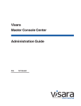
X System Model for the NC
In X terminology, an application process is called a client and the process that
controls the display is called a server. Figure 1-1 shows the X Window System
client-server model, often referred to as core X. The client communicates with
the server via a byte stream, sending X requests and receiving X events from
the server.
The client and server do not necessarily run on the same host. They often
communicate over a network, as shown in Figure 1-1. An X server can listen to
several clients at once, providing input and displaying output for each in a
separate window. A collection of simultaneously executing X clients is called
a session. If necessary, each client can run on a different host, spreading the
load across the system for the most efficient use of available resources.
Figure 1-1 X System Model for the NC
1-2
NCBridge Reference Manual
Network Computer Software
Once the system has been set up, the network is totally transparent. The X
software cannot tell the difference between local clients, that is, applications
running on the same host as the server, and remote clients running on other
hosts. When the proper defaults are in place, users cannot tell the difference,
either.
Network Computer Software
This section provides an overview of the NCBridge software used for booting
and running XP and NC series network computers. The software comes on
CD-ROM discs (also on magnetic tape for VMS only). The media contain boot
files (the X server image), configuration files, fonts, and font tools to support
network computers. Files with .900 extensions (*.900) support NC900 series
network computers and so on, as shown in Table 1-1.
Table 1-1 File Extensions for Supported Models
Binary File Extensions
Models These Files Support
*.900
NC900 Series
*.500
NC200/NC400 Series
*.350
XP100/XP200/XP350/XP400
*.300
XP/NC200/NC400/NC900 Series
X Server
The software environment is the X Window System, Version 11, Release 6. The
X server monitors input from the keyboard and mouse, and sends output to the
display. The server software is available in two options:
• RAM-based — The server is supplied on CD-ROM discs (and magnetic tape
for VMS), loaded onto a host, and downloaded from the host to the network
computer RAM using nfs, tftp or MOP.
• Flash Memory — The server is resident in flash memory on a network
computer.
NCBridge Reference Manual
1-3
Chapter 1
Introduction
Local Clients
Most X applications (clients) run on a host computer, but some local clients can
run on an NCD network computer. Depending on the type of network
computer, the following local clients are available:
• Setup provides a user interface for setting up and viewing network computer
configuration parameters and running utilities such as ping.
• Motif Window Manager provides a local window manager.
• XP Window Manager provides a local window manager.
• HostMenu provides a list of available login hosts.
• Low Memory Indicator displays an alert if available memory falls below a
specified limit.
• Xlock provides a way to lock a network computer’s keyboard only, or the
keyboard and display.
• Input Configuration Manager configures a variety of input devices, such as
lightpens and tablets.
• Netscape and Netscape_Lite clients are web browser clients. Netscape_Lite
is the same as Netscape minus email and news functions.
• TeemX clients for IBM 3270E and 5250 Emulators (latest emulators).
• Session Clients support these sessions:
Telnet VT220 or VT340, LAT VT220 or VT340, CTERM VT220 or VT340,
Serial (TIP) VT220 or VT340, and CSLIP.
• Client Launcher provides a way to start local clients by selecting clients from
a menu.
• Analog Video Player displays analog video sources on a network computer.
• Digital Video Player displays digital video files on a network computer.
1-4
NCBridge Reference Manual
Local Clients
• Audio Player provides a way to record and play audio files on a network
computer.
• Audio Mixer provides a way to record and play several audio sources.
• Authorization Key Manager provides a way to update the authorization keys
of several network computers at once.
• Touchscreen Calibration client provides a graphical interface for calibrating
the Trident Touchscreen.
• XClock client for displaying current time from time-server host.
• WinDD client that allows you to access Windows applications from
Windows NT hosts.
• Llogin client provides LAT login sessions.
• Lfm client allows saving files from a host to an optional local floppy drive.
• Tarantella allows connection to a Tarantella server.
NCBridge Reference Manual
1-5
Chapter 1
1-6
Introduction
NCBridge Reference Manual
Chapter
2
Remote Configuration
Overview
The remote configuration file (xp.cnf) is used to specify the configuration
information for all network computers (NCs) that boot from a specific host. This
facility aids the system administrator in efficiently setting up and maintaining
NCs. All NCs can be controlled from a central location, eliminating the need to
individually set up each one.
Also included is a master copy of the remote configuration file called xp_cnf.txt.
This file is provided as a backup copy to be used in case your xp.cnf file is
corrupted or in some other way becomes unusable.
To use a single remote configuration file to configure different network
computer models, use the remote configuration file (xp.cnf) provided in
.../tekxp/boot/config/ on UNIX systems. For Windows NT and
Windows 2000 hosts, this file is located in ...\tekxp\boot\config\. For
VMS hosts, xp.cnf is located in the TEK$XP_CONFIG:. directory. This file is
read by all NCD NCBridge network computers.
To use separate remote configuration files to configure different network
computers, create the remote configuration files and give them unique names.
Then use the select command to specify which remote configuration file a
network computer is to use. The select command is discussed in the
Restricting Configuration Parameters section in this chapter.
Note: If you had a previous installation, your configuration files were
preserved, and the new configuration files renamed with a .tmpl
suffix. If xp.tmpl exists, compare it to your existing xp.cnf file to
see if features have been added, or if the syntax has changed.
NCBridge Reference Manual
2-1
Chapter 2
Remote Configuration
VMS Logicals
For VMS hosts, the logicals listed in the table below point to model-specific
remote configuration files. By default, these logicals all point to the same
directory. You can display all VMS logicals by issuing a show log command
in VMS. To view only the NCBridge logicals on the VMS system, use the show
log TEK* command. Table 2-1 shows all the NCBridge logicals.
Table 2-1 VMS Logicals
For NC900 Series
TEK$N916_CONFIG:
TEK$N916PL_CONFIG:
TEK$N932_CONFIG:
TEK$N916B2_CONFIG:
TEK$N948_CONFIG:
TEK$N916B2PL_CONFIG:
TEK$N980_CONFIG:
For NC400 Series
TEK$NC400_CONFIG:
TEK$N400X2_CONFIG:
TEK$NC417_CONFIG:
TEK$N400XPC_CONFIG:
TEK$NC421_CONFIG:
TEK$N400WEB_CONFIG:
TEK$N400DM_CONFIG:
For NC200 Series
TEK$NC200E_CONFIG:
TEK$N200X_CONFIG:
TEK$NC200H_CONFIG:
TEK$N200XPC_CONFIG:
TEK$NC215_CONFIG:
TEK$N200XPC2_CONFIG:
TEK$NC217_CONFIG:
TEK$N200XPL_CONFIG:
TEK$NC217H_CONFIG:
TEK$N200WEB_CONFIG:
TEK$NC220S_CONFIG:
TEK$N200FAST_CONFIG:
TEK$NC221H_CONFIG:
For XP400 Series
TEK$XP400_CONFIG:
TEK$XP417C_CONFIG:
TEK$XP400D_CONFIG:
TEK$XP419C_CONFIG:
TEK$XP419G_CONFIG:
For XP350 Series
2-2
TEK$XP350_CONFIG:
TEK$XP356_CONFIG:
TEK$XP354_CONFIG:
TEK$XP358_CONFIG:
NCBridge Reference Manual
VMS Logicals
Table 2-1 VMS Logicals (continued)
For XP200 Series
TEK$XP200_CONFIG:
TEK$XP217C_CONFIG:
TEK$XP200CH_CONFIG:
TEK$XP217CH_CONFIG:
TEK$XP214C_CONFIG:
TEK$XP219CH_CONFIG:
TEK$XP214M_CONFIG:
TEK$XP219MH_CONFIG:
For XP100 Series
TEK$XP100_CONFIG:
TEK$XP117C_CONFIG:
TEK$XP114C_CONFIG:
TEK$XP119C_CONFIG:
TEK$XP115M_CONFIG:
TEK$XP119M_CONFIG:
NCBridge Reference Manual
2-3
Chapter 2
Remote Configuration
Command Syntax
The remote configuration file uses the following command syntax:
• A command-line consists of a single command keyword followed by one or
more parameters. White space, which is any combination of spaces or tabs,
separates the command and its parameters. White space can also precede the
command to improve readability. A command-line is terminated by either a
newline character or a #, which introduces a comment.
• A comment begins with #. Comments and blank lines are ignored. Comments
can appear on the same line as a command; once # is encountered, all
subsequent text is ignored until after the next newline.
• A parameter is either a keyword or a string. A parameter begins with any
character that is not white space, #, or a newline, and is terminated by the
next character that is white space, #, or a newline. A parameter can be
enclosed in double quotation marks. These quotation marks are removed
from the ends of the parameter before the parameter is used. A pair of double
quotation marks with nothing between ("") signifies a null string. If double
quotation marks appear at one end of a parameter but not at the other, the
character is removed, a warning message is printed in the Console, and the
remaining string is used as the parameter.
Note: Some commands take multiple required and/or optional
parameters. You must provide all required parameters for a
command. The order of the commands in the following
sections follows the recommended order for commands
within the remote configuration file. You need not enter a
command unless you want to set the characteristic to
something other than the default. Note that not all commands
have default settings. If a command fails, the parameter is left
unchanged.
2-4
NCBridge Reference Manual
Editing the Remote Configuration File
Editing the Remote Configuration File
To begin, login as root for UNIX hosts, system for VMS hosts, or administrator
for Windows NT hosts. Change the file permissions of the remote configuration
file before you start, making it readable by all, and writable by owner.
All the lines in the file are commented out, with their default values shown. The
recommended strategy is to edit the file to enable only the specific commands
you need to set up your site. User preference entries, such as screen_saver, or
entries where values may vary, such as default_visual, should be left alone.
The order in which commands appear in the remote configuration file is
significant because some commands depend on the prior execution of another
command. For example, xdmcp_server can take either a host name or an IP
address as its parameter. If you use a host name, the name must be in the host
table when the xdmcp_server command executes. Thus all host_table
commands should precede any xdmcp_host commands in the configuration
file. Another example is if you are using an NFS server. In this case, you would
have to define the host name and address in the nfs_table entry before you could
assign it as an NFS server.
If an error is found, an error message with the line number where the error
occurred appears on the system Console window, and command processing
continues. In general, if a command appears more than once, the last setting
read is the one used. For commands that allow multiple settings, such as the
commands that fill tables, each command encountered adds another entry in the
table.
Notes: Settings for TDEnet (an implementation of the DECnet
protocol), MOP, DAP, Cterm, and VMS autologin only apply to
environments with DECnet running on one or more hosts.
DECnet does not support Domain Name Service (DNS). You
must have the DECnet node number defined.
Internet protocol (IP) names, addresses, gateways, tftp, NFS,
Domain Name Service (DNS) and Telnet only apply to
environments using TCP/IP network protocol. You must have
the IP parameters set (see the section, TCP/IP Configuration on
page 2-54 for more information).
NCBridge Reference Manual
2-5
Chapter 2
Remote Configuration
The xp_cnf.txt File
The xp_cnf.txt file is complete with liberal comments and all the settings. This
file should be read carefully and used as a guide in selecting the command-lines
for your xp.cnf file.
Note: Do NOT modify or delete the xp_cnf.txt file. Instead make a copy
for your changes or use the xp.cnf file.
Both xp_cnf.txt and xp.cnf files are located in .../tekxp/boot/config/ on
a UNIX system. For Windows NT and Windows 2000 hosts, these files are
located in ...\tekxp\boot\config\. On VMS hosts, xp.cnf is located in
TEK$XP_CONFIG:. Please refer to the xp_cnf.txt file for detailed information
about xp.cnf commands.
Example Configuration Files
Examples 2-1 and 2-2 show sample remote configuration files for UNIX,
Windows NT, and VMS hosts.
2-6
NCBridge Reference Manual
Example Configuration Files
Example 2-1 Sample UNIX or Windows NT Remote Configuration File
##***** Network Tables *****
#
ip_host_table "128.07.60.01" "oregon"
gateway_table "0.0.0.0" "128.07.60.100"
gateway_table "128.07.70.00" "128.07.60.110"
nfs_table "oregon:/tekxp" "/tekxp" "8192"
#
Note: The aforementioned nfs_table example only works on
Windows NT if NFS is installed on the NT server.
##***** X Environment Configuration *****
#
backing_store ENABLED
host_connect_method WINDD
default_host_list WINDD
#
##***** TCP/IP Configuration *****
#
subnet_mask 255.255.255.0
broadcast_address 128.07.60.255
name_server_1 128.07.60.01
Example 2-2 Sample VMS Remote Configuration File
## $Header: xp.cnf
#
##***** Network Tables *****
#
tde_host_table "11.20::" "idaho::"
#
#
##***** X Environment Configuration *****
#
backing_store ENABLED
host_connect_method VMS
vms_autologin_transport TDENET
vms_autologin_tdenet_host "idaho::"
#
NCBridge Reference Manual
2-7
Chapter 2
Remote Configuration
The sections in this chapter follow the order of the remote configuration file on
the media and are named after the features. The features that apply to each
platform (that each platform supports) are indicated by a check mark ( ♦ ), as
shown in Table 2-2.
Table 2-2 Features by Platform Chart
Feature
XP
NC200 and
NC400
NC900
Network Tables
♦
♦
♦
File Host Configuration
♦
♦
♦
X Environment Configuration*
♦
♦
♦
Boot Configuration
♦
♦
♦
TCP/IP Configuration
♦
♦
♦
TDEnet Configuration Parameters
♦
♦
♦
Serial Port Configuration Parameters
♦
♦
♦
Net to Port Configuration
♦
♦
♦
Keyboard Configuration Parameters
♦
♦
♦
Input Extensions Configuration Parameters
♦
♦
♦
SNMP Configuration
♦
♦
♦
Token-Ring Interface
♦
NC200 only
Local Clients
♦
♦
♦
LAT Configuration
♦
♦
♦
Miscellaneous Functions
♦
♦
♦
Including Other Configuration Files
♦
♦
♦
*One of the commands covered in the X Environment section is the dual_display_configuration,
which is only available on the XP100D, XP400D, and NC400 with dual monitor cards.
2-8
NCBridge Reference Manual
Example Configuration Files
Table 2-2 Features by Platform Chart (continued)
Feature
XP
NC200 and
NC400
NC900
Restricting Configuration Parameters
♦
♦
♦
Tek220 and Tek340 Configuration
♦
♦
♦
Black and White Pixel Compatibility
♦
Flash Memory Configuration
♦
♦
♦
HostMenu Configuration
♦
♦
♦
Local Print Spooler/Printing
♦
♦
♦
DEC Session Manager Configuration
♦
♦
♦
TFTP Daemon
♦
♦
♦
Exiting Telnet
♦
♦
♦
Analog Video Configuration
XP300V and
X317CVJ
Console Configuration
♦
♦
♦
WinDD Configuration
♦
♦
♦
RSHD Configuration
♦
♦
♦
XP400
♦
CSLIP Settings
♦
♦
♦
Script Variables
♦
♦
♦
HW MPEG Player Configuration
NCBridge Reference Manual
2-9
Chapter 2
Remote Configuration
Configuring the Host
This section describes the remote configuration commands for the host
configuration. Here is a list of these commands and their locations:
Command
Page
clear_table . . . . . . . . . . . 2-12
ip_host_table . . . . . . . . . 2-12
tde_host_table . . . . . . . . 2-13
gateway_table . . . . . . . . 2-13
nfs_table. . . . . . . . . . . . . 2-15
ip_host_entry . . . . . . . . . 2-16
tde_host_entry . . . . . . . . 2-16
gateway_entry . . . . . . . . 2-17
nfs_entry . . . . . . . . . . . . 2-17
enable_tdenet . . . . . . . . . 2-18
enable_lat . . . . . . . . . . . . 2-18
lat_service_entries . . . . . 2-19
lat_services_table. . . . . . 2-19
show_lat_services . . . . . 2-20
file_access_1 . . . . . . . . . 2-21
file_host_name_1. . . . . . 2-22
file_path_1 . . . . . . . . . . . 2-23
file_access_2 . . . . . . . . . 2-23
file_host_name_2. . . . . . 2-23
file_path_2 . . . . . . . . . . . 2-23
2-10
NCBridge Reference Manual
Network Tables
Network Tables
The network tables contain entries that are loaded into the network computer
during the boot process. Typically, this is frequently accessed network
information you always want stored in the network computer’s NVRAM, such
as the boot host, login host or font host.
Another typical use for the network table entries in the remote configuration file
is to define host names and addresses for use with other remote configuration
commands. For example, there must be an ip_host_table command with the
appropriate information in order to use an nfs_table command.
When the remote configuration entries are read, existing values in the network
computer’s NVRAM are temporarily overridden. These temporary NVRAM
settings can be saved with the save_current_settings command in the
remote configuration file or with the Save Settings to File option in Setup.
Entries encountered in the remote configuration file are added to the NVRAM
table, overlaying any existing entries, until it is full. Subsequent entries in the
remote configuration file are ignored. Use the RAM table commands
(ip_host_entry, tde_host_entry, gateway_entry, and
nfs_entry) or the optional configuration files hosts.tbl and nodes.tbl to
maintain a complete list of host names and addresses.
There are four network tables whose entries are stored in the NC’s NVRAM.
Each table can have up to four entries. These are the tables:
• ip_host_table is used in environments supporting TCP/IP addressing.
• tde_host_table is used in environments supporting a DECnet protocol.
• gateway_table is used to specify router information in TCP/IP environments.
• nfs_table is used to specify NFS mounts for file and font transfer in
TCP/IP environments.
Also, the following table is stored in RAM:
• lat_services_table is used in environments supporting the LAT protocol.
Note: Additional entries (such as multiple IP host, the host, gateway,
and nfs entries—not tables) are stored in RAM, not NVRAM.
Multiple entries are allowed.
NCBridge Reference Manual
2-11
Chapter 2
Remote Configuration
clear_table
clear_table IP_HOST or TDE_HOST or GATEWAY or NFS or
DISPLAY_ACCESS
Deletes the entries from the specified NVRAM table.
Parameters
IP_HOST
TDE_HOST
GATEWAY
NFS
deletes the entries in the IP host table.
deletes the entries in the TDE host table.
deletes the entries in the Gateway table.
deletes the entries in the NFS table.
DISPLAY_ACCESS deletes the entries in the Display Access table.
In this example, IP host table and NFS table entries are deleted from NVRAM:
clear_table ip_host
clear_table nfs
ip_host_table
ip_host_table ip_address hostname
Specifies Internet host-table entries by Internet Protocol address and host name.
The first four entries of this table can be stored in NVRAM using the Setup Menu
or by using the save_current_settings command in the xp.cnf file.
Additional table entries or entries made with the ip_host_entry command are
stored in RAM. Host resolution can also be accomplished with Domain Name
Service (DNS) providing a DNS host is available. DNS simplifies host
configuration maintenance.
Parameters
ip_address specifies the IP address, which must be in dotted-decimal format.
hostname
specifies the name of the host.
In this example, the host oregon has IP address 128.07.60.01:
ip_host_table "128.07.60.01" "oregon"
Note: Four internet hosts may be specified. For additional hosts, use the
ip_host_entry command or the optional hosts.tbl file described in
Chapter 4 of the NCBridge Installation and Configuration manual for
your operating system.
2-12
NCBridge Reference Manual
tde_host_table
tde_host_table
tde_host_table TDEnet_address node_name
The network computer uses these entries to map TDEnet addresses and names.
The first four entries of this table can be stored in NVRAM using the Setup Menu
or by using the save_current_settings command in the xp.cnf file.
Additional table entries or entries made with the tde_host_entry command are
stored in RAM.
Parameters
TDEnet_address specifies the TDEnet address.
node_name
specifies the name of the host.
In this example, the TDEnet host table contains an entry for the host idaho at
TDEnet address 11.20:
tde_host_table "11.20" "idaho"
Note: Four TDEnet nodes may be specified. For additional nodes, use
the tde_host_entry command or the optional nodes.tbl file
described in Chapter 4 of NCBridge Installation and
Configuration manual for your operating system.
gateway_table
gateway_table ip_net_address ip_gateway_address
The network computer uses this command to specify a gateway-table entry by
network and IP address. Gateway entries correlate the address of a remote network
that the NC needs to access with the address of the gateway host. The first four
entries of this table can be stored in NVRAM using the Setup Menu or the
save_current_settings command in the xp.cnf file. Additional table
entries or entries made with the gateway_entry command are stored in RAM.
Parameters
ip_net_address
specifies the table entry for the network gateway.
ip_gateway_address specifies the IP address for the network gateway. The
addresses must be in decimal-dot format.
In this first example, network 9 is accessed through IP address 128.07.60.100:
gateway_table "9.0.0.0" "128.07.60.100"
NCBridge Reference Manual
2-13
Chapter 2
Remote Configuration
In this second example, all networks not explicitly specified—as in the previous
example—are accessed through IP address 128.07.60.100:
gateway_table "0.0.0.0" "128.07.60.100"
Note: Four gateways may be specified. For additional gateways, use
the gateway_entry command or the optional gateway.tbl file
described in Chapter 4 of the NCD NCBridge Installation and
Configuration manual for your operating system.
Using the Route Manager
The route manager enables a site to take advantage of multiple routers: if a
router fails for longer than the TCP connection timeout, the route manager
routes traffic to other routers to minimize the lost connections. Route manager
balances the network load among the remaining routers until the down router
comes back on line. The route manager continues to check the status of the
down router, and waits until it is up and back at normal capacity before
rerouting any connections back. The route manager is transparent to the user.
The route manager is started with the xp.cnf start command:
start ROUTE_MGR
The route manager uses routers specified with the gateway_table and
gateway_entry remote configuration commands, the gateway.tbl file, the
bootptab file (if the terminal is configured to use bootp protocol), or the
Gateway screen of the Network Tables and Utilities menu in Setup. If different
default gateways are specified in any of these locations, then the bootrom uses
the first specification and the os uses the last. Both routers need to be up in order
for the network computer to boot.
2-14
NCBridge Reference Manual
nfs_table
nfs_table
nfs_table file_system_name local_directory transfer_size
The network computer uses these table entries to map remote file systems to
local mount points. You can specify a transfer read size for each mount point.
NFS directories are frequently used to access additional fonts. The directories
must be exported on the host to be accessible to the network computer. To
access files or fonts through NFS, either file_access_1 or file_access_2 must be
set to NFS. Additional table entries or entries made with the nfs_entry
command are stored in RAM.
Notes: Before NFS directories can be specified, the remote host must
either be specified by the ip_host_table command, stored
in NVRAM, or domain name service must be enabled. NFS
must also be running on your host with the directories
exported. Check the NCD NCBridge Installation and
Configuration manual for NFS setup information or consult
the vendor documentation for your host computer.
The first four NFS table entries can be stored in NVRAM via
the Setup Menu or by using the save_current_settings
command in the xp.cnf file. Additional table entries are stored
in RAM. You can also store table entries in RAM using the
nfs_entry command.
Parameters
file_system_name specifies the remote host path.
local_directory
specifies the local path.
transfer_size
specifies the block size for NFS transfers (128 to 8192).
In this example, /u1/tekxp is the path defined for the exported NFS directory
from host oregon:
nfs_table "oregon:/ul/tekxp" "/tekxp" "8192"
The following examples illustrate setting the transfer block size from oregon at
8192 bytes and the transfer block size from arizona at 1024 bytes.
nfs_table "oregon:/tekxp" "/tekxp" “8192”
nfs_table "arizona:/vol" "/volp" “1024”
NCBridge Reference Manual
2-15
Chapter 2
Remote Configuration
ip_host_entry
ip_host_entry ip_address hostname
Specifies Internet Protocol host addresses and names and stores them in RAM,
not NVRAM. Multiple entries may be listed in the xp.cnf file.
Parameters
ip_address
specifies the IP address in decimal-dot format.
hostname
specifies the name of the host.
The following example shows an entry for a host called “vancouver”:
ip_host_entry "128.07.60.01""vancouver"
tde_host_entry
tde_host_entry TDEnet_address node_name
Specifies TDEnet addresses and host names and stores them in RAM, not
NVRAM. Multiple entries may be listed in the xp.cnf file.
Parameters
TDEnet_address specifies the TDEnet address.
node_name
specifies the name of the host.
The following example shows an entry for a host called “washington” (note the
double colon syntax):
ip_host_entry "11.20::""washington"
2-16
NCBridge Reference Manual
gateway_entry
gateway_entry
gateway_entry ip_net_address ip_gateway_address
This command maps network addresses to gateway routers and stores them in
RAM, not NVRAM. Multiple entries may be listed in the xp.cnf file. Refer to
Using the Route Manager on page 2-14 for information on multiple routers.
Parameters
ip_net_address
specifies the table entry for the network gateway.
ip_gateway_address specifies the gateway IP address in decimal-dot format
In the following examples, the first example shows a typical gateway
configuration. The second example shows a default gateway for networks with
a single node going to the outside world.
gateway_entry "128.07.70.00""128.07.60.110"
gateway_entry "0.0.0.0""128.07.60.1"
nfs_entry
nfs_entry file_system_name local_directory transfer_size
Maps NFS mount points to local directory structures and stores them in RAM,
not NVRAM. Multiple entries may be listed in the xp.cnf file. You can specify
a transfer read size for each mount point.
Parameters
file_system_name specifies the remote host path.
local_directory
specifies the local path.
transfer_size specifies the block size for NFS transfers (128 to 8192).
The following example shows a typical nfs entry:
nfs_entry "oregon:/tekxp""/tekxp""8192"
nfs_entry "arizona:/vol""volp""1024"
NCBridge Reference Manual
2-17
Chapter 2
Remote Configuration
enable_tdenet
enable_tdenet YES or NO
Specifies whether TDEnet is started via the remote configuration file. TDEnet
must be authorized for the network computer, and then enabled. For
information about authorizing a feature, refer to the Authorize command in
Chapter 5, Boot Monitor.
Parameters
YES
specifies that TDEnet is enabled. This is the default if the TDEnet
address is entered and the option is authorized on the network
computer.
NO
specifies the TDEnet is not enabled. This is the default if no
TDEnet address is entered.
In this example, TDEnet is enabled:
enable_tdenet YES
enable_lat
enable_lat YES or NO
Specifies whether LAT is started via the remote configuration file.
Parameters
YES
specifies that LAT is enabled. This is the default if authorized on
the network computer.
NO
specifies that LAT is not enabled.
In this example, LAT is not enabled:
enable_lat NO
2-18
NCBridge Reference Manual
lat_service_entries
lat_service_entries
lat_service_entries integer
Specifies the LAT services tables and the number of reserved LAT service
entries that the network computer can retain. These entries are unavailable until
the broadcast service advertisement has been received by the network
computer. LAT is available only to those network computers that have the
DECnet option enabled.
Parameters
integer
specifies the number of reserved LAT service entries that the
network computer can retain. Keep the number of entries as few
as possible to reduce memory usage. The maximum number of
entries is 32,767 (default 120).
In this example, there are 120 reserved LAT service entries:
lat_service_entries 120
lat_services_table
lat_services_table node_name service_name
Reserves space for LAT services from a particular node that the network
computer can connect to. The maximum number of entries in the
lat_services_table is approximately 20. These nodes appear in the HostMenu
list for LAT entries (refer to the HostMenu topic later in this chapter).
Parameters
node_name specifies the node name on which to reserve space. The name can
be from 1 to 16 characters (any combination of alphanumeric and
ASCII codes 192-253).
service_namespecifies the LAT service. The name can be from 1 to 16
characters (any combination of alphanumeric and ASCII codes
192-253).
In this example, the host name is oregon and the LAT service is oregon1:
lat_services_table "oregon" "oregon1"
NCBridge Reference Manual
2-19
Chapter 2
Remote Configuration
show_lat_services
show_lat_services YES or NO
Specifies whether the available LAT services display in the HostMenu client
and in Tekterm sessions using LLogin (LAT session login). If they do not
display, they are not available to users.
Parameters
YES
specifies that the LAT services display and are available to users.
This is the default.
NO
specifies that the available LAT services do not display.
In this example, available LAT services do not display in the HostMenu, or in
Tekterm sessions:
show_lat_services NO
2-20
NCBridge Reference Manual
File Host Configuration
File Host Configuration
The network computer searches for the .tbl and other configuration files based
on the information set up in this section.
During the boot process, the network computer uses the primary host settings
to search for the other configuration files. If the files are not found or the
primary host is not accessible, the secondary settings, if specified, are used. The
hostname and path formats change, depending on the access method.
file_access_1
file_access_1 OFF or NFS or TFTP or DAP
Specifies the access method to connect to the primary host, containing
configuration files. The host is specified by file_host_name_1.
Parameters
OFF
specifies that the primary path is not used. This is the default.
NFS
specifies that the connection to the host is through NFS. NFS can
be used as the file access method to any host running NFS.
TFTP
specifies that the connection to the host is through TFTP. TFTP
can be used as the file access method for hosts supporting TCP/IP.
DAP
specifies that the connection to the host is through DAP.
In this example, files are accessed through TFTP:
file_access_1 TFTP
NCBridge Reference Manual
2-21
Chapter 2
Remote Configuration
file_host_name_1
file_host_name_1 ip_address or host_name or TDEnet_address or
TDEnet_nodename
Specifies the primary host where the network computer obtains configuration
information, such as a table of font file directories. If file_access_1 is NFS, the
file_host_name should be set to null (""). If file_access_1 is TFTP or DAP,
enter the host name or IP address (use colon format for DAP; use decimal-dot
format for TFTP).
Parameters
ip_address
specifies the IP address of the host. If file_access_1 is NFS,
set this to null ("").
host_name
specifies the name of the host. To use a host name, it must
be specified in an ip_host_table command, stored in
NVRAM, or Name Service must be enabled on the network
computer.
TDEnet_address
specifies the TDEnet address of the host.
TDEnet_nodename specifies the name of the host. To use a host name, it must
be specified in a tde_host_table command, stored in
NVRAM, or Name Service must be enabled on the network
computer.
In this example, the host is the NFS directory:
file_host_name_1 ""
In this example, the TFTP host directory is montana:
file_host_name_1 "montana"
In this example, the TFTP host is at IP address 128.07.60.02:
file_host_name_1 "128.07.60.02"
In this example, the TDEnet host is at node address 11.25:
file_host_name_1 "11.25::"
2-22
NCBridge Reference Manual
file_path_1
file_path_1
file_path_1 pathname
The network computer uses this entry as the directory to search for
configuration and font files on the primary host.
Parameters
pathname
specifies the path to the configuration and font files. The default
path is /tekxp/boot/config for UNIX hosts, or TEK$XP_CONFIG:
for VMS hosts (unless you change the VMS logicals to point to
model specific configuration files).
In this example, the path to the .tbl files is TEK$XP_CONFIG:
file_path_1 "TEK$XP_CONFIG:"
file_access_2, file_host_name_2, file_path_2
The network computer uses these commands similar to the file_access_1,
file_host_name_1, and file_path_1 commands for the secondary host.
During the boot process, if the .tbl files are not found on the primary host and
path, or if the primary host is not accessible, the secondary host and path, if
specified, are searched. If the files are found, they are accessed according to the
specified secondary protocol.
These examples show files accessed through NFS:
file_access_2 NFS
file_host_name_2 ""
file_path_2 "/tekxp/boot/config"
The previous example assumes that the nfs.tbl contains an entry such as:
montana:/u1/tekxp /tekxp
NCBridge Reference Manual
2-23
Chapter 2
Remote Configuration
Configuring the X Environment
This section describes the commands for X environment configuration:
Command
Page
retain_x_settings . . . . . . . . . . . . . . 2-25
backing_store . . . . . . . . . . . . . . . . . 2-25
prior_xserver_compatibility. . . . . . 2-26
dual_display_configuration . . . . . . 2-27
display_access_table . . . . . . . . . . . 2-27
enable_access_control . . . . . . . . . . 2-28
enable_bell_speaker. . . . . . . . . . . . 2-29
default_visual. . . . . . . . . . . . . . . . . 2-30
root_depth . . . . . . . . . . . . . . . . . . . 2-32
host_connect_method . . . . . . . . . . 2-34
default_host_list. . . . . . . . . . . . . . . 2-35
xdmcp_connect . . . . . . . . . . . . . . . 2-37
primary_xdmcp_server . . . . . . . . .2-38
secondary_xdmcp_server. . . . . . . . 2-38
xdmcp_keepalive . . . . . . . . . . . . . .2-38
xdmcp_keepalive_timeout . . . . . . . 2-39
xdmcp_keepalive_wait_timeout . . 2-39
vms_autologin_transport . . . . . . . . 2-40
vms_autologin_tdenet_host . . . . . . 2-40
vms_autologin_tcpip_host . . . . . . . 2-41
screen_saver. . . . . . . . . . . . . . . . . . 2-42
enable_xshm . . . . . . . . . . . . . . . . . 2-43
enable_xv . . . . . . . . . . . . . . . . . . . . 2-43
old_decwin_compatible . . . . . . . . . 2-44
vendor_string . . . . . . . . . . . . . . . . . 2-44
font_cache_limit . . . . . . . . . . . . . . 2-45
2-24
NCBridge Reference Manual
retain_x_settings
retain_x_settings
retain_x_settings YES or NO
The network computer uses this entry to determine if settings are saved when
the X server resets after the last X client connection to the server closes.
Parameters
YES
specifies that the X server does not reset when logging out. The
root window and settings will remain (default).
NO
specifies that the X server discards settings, including root
window properties and device attributes, and restores default font
paths.
In this example, the server saves the settings:
retain_x_settings YES
backing_store
backing_store DISABLED or WHENMAPPED or ENABLED or
ALWAYSWHENMAPPED
Specifies whether the network computer saves obscured pixels when a window
is obscured or unmapped. When enabled, the network computer uses this entry
to request the X server to maintain pixels in portions of client windows that are
obscured. The advantage of using “ALWAYSWHENMAPPED” is that every
obscured window pixel is saved in RAM, making window operations faster.
Keep in mind that this uses RAM resources.
Parameters
DISABLED
specifies that backing_store is disabled and client requests
are denied.
WHENMAPPED specifies that backing_store is enabled and the default
client request is used except for the Always request.
WHENMAPPED is used if a client requests Always.
ENABLED
specifies that backing_store is enabled and the default
client request is used.
NCBridge Reference Manual
2-25
Chapter 2
Remote Configuration
ALWAYSWHENMAPPED specifies that WHENMAPPED is used if the
client does not make a request.
Note: Using WHENMAPPED or ALWAYSWHENMAPPED can use
considerable network computer memory.
Table 2-3 shows the effect that each parameter has on client requests. Note that
the levels of backing store capability increase from lowest to highest.
Table 2-3 Effect of backing_store on Client Request
Client Requests
Parameters
Default
NotUseful
WhenMapped
Always
DISABLED
NotUseful
NotUseful
NotUseful
NotUseful
WHENMAPPED
NotUseful
NotUseful
WhenMapped
WhenMapped
ENABLED
NotUseful
NotUseful
WhenMapped
Always
WhenMapped
WhenMapped
Always
ALWAYSWHENMAPPED WhenMapped
In this example, the client can request that the X server saves pixels when the
window is mapped:
backing_store WHENMAPPED
prior_xserver_compatibility
prior_xserver_compatibility YES or NO
Specifies that the X server reads the fonts.tbl and xhosts.tbl files using the same
method as was used in Version 8.0 and earlier software.
Note: It is recommended that you do not use this command.
Parameters
2-26
YES
specifies that the X server reads the fonts.tbl and xhosts.tbl files
in the same manner as previous versions of the software.
NO
specifies that default information in the fonts.tbl and xhosts.tbl
files is saved so that server resets do not require these files to be
read again. This is the default.
NCBridge Reference Manual
dual_display_configuration
dual_display_configuration
This feature is only available on XP100D, XP400D, and NC400 models that
have the optional dual monitor card.
dual_display_configuration HORIZONTAL or VERTICAL or MONOHEAD
Specifies whether multiple displays are positioned side by side, stacked
vertically, or whether to use only a single display.
Parameters
HORIZONTAL specifies that multiple displays are arranged side by side.
VERTICAL
specifies that multiple displays are stacked vertically.
MONOHEAD
specifies that a single display is used.
In this example, multiple displays are arranged side by side:
dual_display_configuration HORIZONTAL
display_access_table
display_access_table ip_address or ip_hostname or tdenet_address:: or
tdenet_node::
The display access table allows the specified hosts to access the network
computer. These entries are added to the network computer’s display access list.
Only hosts entered here (or in NVRAM) can access the X server on the network
computer and open windows or make other changes. Other hosts can be added in
the xhosts.tbl file if enable_access_control is set to YES. They can access the
display but cannot change the access table or the state of access control.
This command requires either an IP address, host name (specify with
ip_host_table or enable Name Service on the network computer), node address
followed by double colons (::), or node name followed by double colons (::)
(specify with tde_host_table).
Note: If connecting to a VMS host via the HostMenu or
host_connect_method, and logging in using the DECwindows
login banner, the log-in host does not have to be listed in the
display_access_table (i.e., xhosts.tbl).
NCBridge Reference Manual
2-27
Chapter 2
Remote Configuration
Note: For VMS hosts that use access control, the host name must be
defined in the network computer’s TDEnet host table (i.e.,
nodes.tbl). If using the DECwindows security window to control
access to your network computer, the name of the host running
the session manager must be defined in the network computer.
Parameters
ip_address
specifies the host’s IP address.
ip_hostname
specifies the host’s name.
tdenet_address:: specifies the host’s TDEnet address.
tdenet_node::
specifies the name of the TDEnet host.
In this example, the display access table contains the hosts oregon and utah:
display_access_table "oregon" #TCP/IP name
display_access_table "utah::" #DECnet name
enable_access_control
enable_access_control YES or NO
Specifies whether access to the network computer is restricted to the hosts listed
in the display access table.
Parameters
YES
specifies that access to the network computer is restricted to hosts
listed in the display access table.
NO
specifies that access to the network computer is not restricted.
This is the default.
In this example, access to the network computer is restricted to the hosts listed
in the display access table:
enable_access_control YES
2-28
NCBridge Reference Manual
enable_bell_speaker
enable_bell_speaker
enable_bell_speaker YES or NO
This command specifies whether the X server bell tone is enabled through
either the optional audio speaker on the XP series or the standard speaker on the
NC series. By default, a bell tone is always enabled. This command switches
from the standard speaker to the high quality audio speaker, if installed. By
using this command, a user can adjust the bell volume, which is not possible
with the standard speaker.
The bell is heard through the internal speaker. If the external speakers or
headphones are plugged into the audio output jack, the bell is heard through the
attached device. The bell preempts any audio output in progress from the local
Audio and Digital Video Players. It also preempts audio controls set by audio
clients, such as volume control, output gain, and mute control. The volume,
pitch, and duration of the bell are controlled by X applications, for example, the
xset utility. If the audio card is not installed, this command is ignored and the
internal bell is used by default. The internal bell is controlled only through the
xset utility.
Parameters
YES
specifies that the bell speaker is enabled.
NO
specifies that the bell speaker is disabled.
In this example, the bell speaker is enabled:
enable_bell_speaker YES
NCBridge Reference Manual
2-29
Chapter 2
Remote Configuration
default_visual
default_visual PSEUDOCOLOR or DIRECTCOLOR or STATICCOLOR
or TRUECOLOR or STATICGRAY or GRAYSCALE
Specifies the default visual type. See Table 2-4 on page 2-31. The network
computer uses this entry to determine the class of colormaps used for the root
window. Typically, it is best to let each network computer use the default by
leaving this command commented out. Bitonal (grayscale) devices ignore this
setting.
Parameters
PSEUDOCOLOR causes a pixel value to be used as an index into a colormap
to produce independent RGB values.
DIRECTCOLOR causes a pixel value to decompose into separate RGB
subfields. Each subfield separately indexes a colormap for
the corresponding value.
STATICCOLOR
causes a pixel value to be used as an index into a colormap
(that has predefined read-only RGB values) to produce
independent RGB values.
TRUECOLOR
causes a pixel value to decompose into separate RGB
subfields. Each subfield separately indexes a colormap
(that has predefined read-only RGB values) for the
corresponding value.
STATICGRAY
causes a pixel value to be used as an index into a graymap
(that has predefined read-only gray values) for the
corresponding gray value.
GRAYSCALE
causes a pixel value to index a graymap for the
corresponding gray value.
The default is either PSEUDOCOLOR or GRAYSCALE depending on the
monitor capabilities.
2-30
NCBridge Reference Manual
default_visual
Table 2-4 shows that the screen can be color or grayscale, can have a color map
that is writable or read-only, and can also have a colormap whose indices are
decomposed into separate RGB pieces (if you are using a color screen).
Table 2-4 Visual Types
Color
Grayscale
RGB Type
Read Only
Read/Write
Read Only
Read/Write
Undecomposed
Static Color
Pseudo Color
Static Gray
Gray Scale
Decomposed
True Color
Direct Color
In this example, the visual type is set to DIRECTCOLOR, meaning that the
default visual colormap is writable and decomposed into separate RGB pieces:
default_visual DIRECTCOLOR
NCBridge Reference Manual
2-31
Chapter 2
Remote Configuration
root_depth
root_depth bit_planes
All NC900 network computers can take advantage of NCBridge’s 16- or 24-bit
color support. Any NC200 or NC400 that has the additional 2MB of video
memory (option V2 or NCFV2) can support 16-bit color mode.
When a network computer is configured to operate in 16-bit plane mode, its X
server exports a 16-bit plane TrueColor or DirectColor visual, so the
application can display 65,536 colors instead of only 256 colors in 8-bit plane
mode. That means the user can see better visual effects on applications that can
take advantage of 16-bit color depth. Running your network computer in 16- or
24-bit color mode also eliminates irksome color flashes that occur when
multiple color-intensive applications run simultaneously.
Parameters
bit_planes
specifies the bit-depth of the color.
In this example, the bit-depth color value is 16 (65,536 colors):
root_depth 16 # [8 | 16 | 24 | 8&16 | 16&8 | 24&8]
Simultiple Color
The values 8 & 16, 16 & 8, and 24 & 8 support the Simultiple Color feature.
See the NCDBridge User Manual for details.
Limitations
Some clients (host or local) will not work in 16- or 24-bit color mode. For
example:
• The WinDD ICA client requires 8-bit PseudoColor and cannot be used in 16or 24-bit color mode. If you try to launch a WinDD ICA client in 16-bit color
mode, the ICA client writes a message to the console stating that it “cannot
find the PseudoColor visual” and exits.
• The Vplay client (digital video) is not supported in 16- or 24-bit color mode.
These are the only local clients that do not work in 16- or 24-bit color mode.
2-32
NCBridge Reference Manual
root_depth
Another limitation is that there is a trade-off between screen resolution and
root-depth and the default visual type. The combination of these settings cannot
exceed the total installed graphics memory. Invalid settings are ignored.
NCBridge Reference Manual
2-33
Chapter 2
Remote Configuration
host_connect_method
host_connect_method DISABLED or HOSTMENU or XDMCP_DIRECT or
XDMCP_INDIRECT or VMS_TDE or VMS_TCP or TELNET or CTERM or
LAT or SERIAL0 or SERIAL1 or WINDD or Netscape
Specifies the method of connecting to the host.
Parameters
DISABLED
specifies that you must use the Client Launcher to
invoke a Telnet session on the host.
HOSTMENU
specifies that you use the HostMenu client to connect to
a host. This is the default.
XDMCP_DIRECT
specifies that XDMCP (X Display Manager Control
Protocol) can display a login window on the network
computer, if xdm is running on the host specified with
the xdmcp_server command, and if XDMCP is
enabled on the host.
To use a host name, it must be specified by the
ip_host_table command, stored in NVRAM, or
enable Name Service on the network computer. If the
specified host’s address is zero, then the network
computer broadcasts to the boot host.
XDMCP_INDIRECT specifies that the network computer broadcasts to a
name server (if using DNS).
VMS
specifies that DECwindows displays a login window on
the network computer, if the TDEnet option is installed on
the host. The transport is set with the
vms_autologin_transport command, and the host is
set with vms_autologin_tdenet_host.
TELNET, CTERM,
LAT, SERIAL0,
SERIAL1, WINDD
opens a session window where you can establish
connections to a host. Specify one of the available
sessions.
In this example, the network computer connects to the host via xdmcp_direct:
host_connect_method XDMCP_DIRECT
2-34
NCBridge Reference Manual
default_host_list
default_host_list
default_host_list XDMCP or VMS_TDE or VMS_TCP or TELNET or
CTERM or LAT or IBM or WINDD
Specifies which group of hosts display on the HostMenu client after powering
on the network computer.
Parameters
XDMCP
displays the list of available XDMCP servers.
VMS_TDE displays the list of available VMS TDEnet servers.
VMS_TCP displays the list of available VMS TCP/IP servers.
TELNET
displays the list of available TELNET servers.
CTERM
displays the list of available CTERM servers.
LAT
displays the list of available LAT servers.
IBM
displays the list of available IBM hosts to which you can connect
using 3270.
WINDD
displays the list of available Windows NT servers. Windows NT
servers are added with the windd_menu_entry command.
NCBridge Reference Manual
2-35
Chapter 2
Remote Configuration
XDMCP Security Features
The XDMCP Direct List feature allows system administrators to better control
which hosts are available to users. You can specify a list of hosts that respond
when users boot a network computer, bypassing the HostMenu client.
To use the XDMCP Direct List feature, use the following xp.cnf commands:
host_connect_method XDMCP_DIRECT
xdmcp_connect
DIRECT
xdmcp_server
ip_address or host_name of the host(s) that you want
the user to use. You can repeat this command, listing as
many hosts as you wish. List the hosts in priority. The
first host listed with this command can be saved in
NVRAM. Subsequent hosts cannot be saved in
NVRAM.
When the network computer boots, only the hosts
specified with this command are queried. The list has
an implied priority order. For example, when the
network computer boots, the XDM login banner of the
highest priority host available displays.
2-36
NCBridge Reference Manual
xdmcp_connect
xdmcp_connect
xdmcp_connect BROADCAST or DIRECT or INDIRECT
Specifies an additional method of connecting to the host specified by
xdmcp_server using XDMCP.
Parameters
BROADCAST specifies that the network computer broadcasts a request for
XDMCP server(s) to all local hosts. The HostMenu client
displays a menu of all hosts (running xdm) who responded to
the request. BROADCAST requires Release 4 (or higher) of
X11 (X11R4). This is the default.
DIRECT
specifies that the network computer broadcasts to the host
specified with the xdmcp_server command. To use a host
name, it must be specified by the ip_host_table
command, stored in NVRAM, or enable Name Service on the
network computer. If the specified host’s address is zero, then
the network computer broadcasts to the boot host.
INDIRECT
specifies that the network computer broadcasts to a name
server (if using DNS).
Notes: If xdm keeps timing out, you can send keepalive requests by
setting xdmcp_keepalive to ON. Refer to the
xdmcp_keepalive command.
For information about XDMCP security features, refer to the
XDMCP Security Features topic on page 2-36.
In this example, the network computer connects directly to the host specified by
xdmcp_server:
xdmcp_connect DIRECT
NCBridge Reference Manual
2-37
Chapter 2
Remote Configuration
primary_xdmcp_server
primary_xdmcp_server ip_address or hostname
Specifies the primary XDMCP host by IP address or name. The network
computer uses this entry as the host to which the network computer connects.
If domain name service is not enabled and you specify the host by name, you
must specify the host in the ip_host_table entry. If the xdmcp_connect method
is BROADCAST, an entry is not needed in this command.
Parameters
ip_address
specifies the IP address of the host.
hostname
specifies the name of the host.
In this example, the network computer connects to the host at IP address
128.07.60.01:
primary_xdmcp_server "128.07.60.01"
secondary_xdmcp_server
secondary_xdmcp_server ip_address or hostname
Specifies the secondary XDMCP host by IP address or name. Similar to
primary_xdmcp_server previously described.
xdmcp_keepalive
xdmcp_keepalive ON or OFF
The network computer uses this entry to control whether keepalive requests are
sent to xdm.
Parameters
ON
specifies that keepalive requests are sent to xdm.
OFF
specifies that no keepalive requests are sent to xdm. This is the
default.
In this example, the keepalive requests are not sent to xdm:
xdmcp_keepalive OFF
2-38
NCBridge Reference Manual
xdmcp_keepalive_timeout
Note: If you have either the NC console or the NC launcher (or both)
up on the NC screen, your session won’t time out. Both console
and launcher constantly do XSync’s which cause messages to go
between themselves. This message exchange causes the X server
to think that the session is alive. The X server doesn’t distinguish
local clients from host-based clients. For additional information,
see the NCBridge Software User Manual.
xdmcp_keepalive_timeout
xdmcp_keepalive _timeout interger
The network computer sends a message to the xdm host after the
xdmcp_keepalive_timeout has expired.
Parameters
interval
specifies the initial amount of time after which the
xdmcp_keepalive_timeout expires and the network computer
sends its first message to the xdm host. The available range is
from 1 to 255 minutes (default is 3).
In this example, the keepalive_timeout requests expires after two minutes:
xdmcp_keepalive_timeout 2
xdmcp_keepalive_wait_timeout
xdmcp_keepalive_wait_timeout integer
The network computer tries to obtain a response from the xdm host three times.
If after three attempts, the xdm host does not reply, the network computer
assumes that the xdm host is not available and closes all the windows on the
screen.
Parameters
integer
specifies the amount of time the network computer waits before
sending another message to the xdm host. The available range is
from 1 to 255 seconds (default is 20).
In this example, the keepalive_wait_timeout waits 25 seconds before sending
another message to the xdm host:
xdmcp_keepalive_wait_timeout 25
NCBridge Reference Manual
2-39
Chapter 2
Remote Configuration
vms_autologin_transport
vms_autologin_transport DISABLED or TDENET or TCPIP
Specifies the network protocol used to display the VMS autologin window. Use
this if you are using VMS as the host_connect_method.
Parameters
DISABLED disables vms_autologin_transport.
TDENET
specifies using the DECnet protocol.
TCPIP
specifies using the TCP/IP network protocol.
In this example, the network protocol used is TCP/IP:
vms_autologin_transport TCPIP
vms_autologin_tdenet_host
vms_autologin_tdenet_host TDEnet_address or hostname
Specifies the DECnet host to connect to when using the VMS host connect
method with TDEnet.
Parameters
TDEnet_address specifies the DECnet address of the host.
hostname
specifies the name of the host.
In this example, the network computer connects to the TDEnet host idaho:
vms_autologin_tdenet_host "idaho::"
Note: To change the autologin feature from one host to a different host,
specify the new autologin host and then turn the network
computer off for at least two minutes. When you power up, the
login window appears for the new host.
2-40
NCBridge Reference Manual
vms_autologin_tcpip_host
vms_autologin_tcpip_host
vms_autologin_tcpip_host ip_address or hostname
specifies the TCP/IP host to connect to when using the TCP/IP
host connect method.
Parameters
ip_address
specifies the IP address of the host.
hostname
specifies the name of the host.
In this example, the network computer connects to the TCP/IP host oregon:
vms_autologin_tcpip_host "oregon"
Note: To change the autologin feature from one host to a different host,
specify the new autologin host and then turn the network
computer off for at least two minutes. When you power up, the
login window appears for the new host.
NCBridge Reference Manual
2-41
Chapter 2
Remote Configuration
screen_saver
screen_saver ON or OFF or POWERSAVE
Specifies whether the screen blanks after 10 minutes of keyboard and mouse
inactivity. You can specify a different duration of inactivity with the xset
command.
Note: Some clients override this setting by automatically turning
screen_saver off and on during their execution.
Parameters
ON
sets the screen to blank after 10 minutes of inactivity. This is the
default. The POWERSAVE setting extends the life of the screen
better than ON.
OFF
turns off the screen blank feature.
POWERSAVE
specifies that the Powersave feature takes effect after 10 minutes
of inactivity. Powersave is an energy-saving feature that has three
phases:
Stand by − after 10 minutes of inactivity, the screen blanks and
returns immediately when a key is pressed.
Suspend − after the screen has been on Stand by for 10 minutes,
the screen remains blank and goes into Suspend mode, using less
energy than in Stand by mode. When a key is pressed, the screen
display returns after a few moments.
Off − after the screen has been in Suspend mode for 10 minutes,
the screen remains blank and goes into Off mode, using minimum
energy. When a key is pressed, the screen display returns but
takes longer than in Stand by or Suspend modes.
Note: The Powersave feature is not available on the XP330 series
network computer. For power saving features, the monitor must
be “Energy Star” compatible.
In this example, the screen blanks after 10 minutes of inactivity:
screen_saver ON
2-42
NCBridge Reference Manual
Miscellaneous X Settings
Miscellaneous X Settings
enable_xshm
enable_xshm
This command specifies that the X Shared Memory extension is enabled. There
are no parameters. Issue the command to enable or comment out the command to
not enable.
enable_xv
enable_xv YES or NO
This enables the XV server extension. It allows you to use any analog or digital
video client. This includes the local Analog Video Player if the Analog Video
hardware is present and the local MPEG Video Player if the MPEG Video option
is present. XV must be enabled to use the Analog Video or MPEG Video Player.
Parameters
YES
specifies that xv is enabled. This is the default if the Analog Video
hardware is present.
NO
specifies that xv is not enabled. This is the default if the analog
video hardware is not present.
In this example, xv is enabled:
enable_xv YES
NCBridge Reference Manual
2-43
Chapter 2
Remote Configuration
old_decwin_compatible
old_decwin_compatible YES or NO
Older DECwindows clients may expect the X server to only handle bitmap and
image data in least significant byte (LSB) order, resulting in scrambled images.
To allow these older clients to work properly, enable old_decwin_compatible.
If you do not enable this command, older applications may not display
correctly, for example, DECwrite graphic attributes and objects, and fonts over
36 points in size.
Parameters
YES
specifies that older DECwindows clients can be used.
NO
specifies that older DECwindows clients cannot be used.
In this example, older DECwindows clients are to be used:
old_decwin_compatible YES
vendor_string
vendor_string string
Use this command only if using a VT200/LK401 keyboard with a DEC system
(VMS or ULTRIX) running DECwindows applications. Some DECwindows
applications check the vendor string to determine how the Delete key works on the
keyboard (delete the character to the left or to the right of the cursor).
Parameters
string
enter the following string if using a VT200/LK401 keyboard on a
DEC system with DECwindows applications:
DECWINDOWS (Compatibility String) NCD, Inc.
In this example, a VT200/LK401 keyboard is used with a DEC system running
DECwindows applications:
vendor_string "DECWINDOWS (Compatibility String) NCD, Inc."
2-44
NCBridge Reference Manual
font_cache_limit
font_cache_limit
font_cache_limit amount
Specifies the amount of memory (in kilobytes) to allow for font caching. Fonts
are stored in the font cache even if the client closes. To empty the font cache,
reset the server, or select the Empty Font Cache option in Setup. For
information about Setup options, refer to Chapter 4, Setup.
Note: The font cache is automatically flushed if available memory is
less than the minimum amount set with the Low Memory
Indicator. Once memory is available, the font cache can resume
storing fonts. Refer to the Start and Preload commands for
information about the Low Memory Indicator.
Parameters
amount
specifies the amount of memory in kilobytes to allow for font
caching (from 0 to 99999). For X-window applications, an
allocation of 500 kbytes is recommended. If only WinDD ICA is
used, then 50 kbytes is appropriate.
In this example, the font cache is 50 kilobytes:
font_cache_limit 50
NCBridge Reference Manual
2-45
Chapter 2
Remote Configuration
Boot Configuration
This section describes the commands within the remote configuration file that
specify the boot configuration. These commands and their locations are:
Command
Page
boot_method / boot_method_2 . . . . . . 2-47
boot_host_name / boot_host_name_2 . 2-49
boot_path / boot_path_2 . . . . . . . . . . . 2-50
determine_address_from . . . . . . . . . . . 2-51
boot_delay . . . . . . . . . . . . . . . . . . . . . . 2-52
verbose_boot_msg . . . . . . . . . . . . . . . . 2-52
enable_boot_interrupt . . . . . . . . . . . . . 2-53
boot_config_type . . . . . . . . . . . . . . . . . 2-53
Note: For network computers that boot from ROM, you can specify
bootp or DHCP as a backup booting strategy. This example
shows a bootp setting:
boot_method ROM
boot_host_name2 Set to host running bootp
determine_address_from NETWORK
2-46
NCBridge Reference Manual
boot_method / boot_method_2
boot_method / boot_method_2
boot_method TFTP or NFS or MOP or ROM
Specifies the network computer boot method. One or two boot methods can be
specified. If the last boot method tried is NFS, and the mount point fails, the
network computer tries to boot using TFTP and the current boot path. The
secondary boot method feature does not apply to MOP.
Parameters
TFTP
specifies that the network computer boots using TFTP.
NFS [Read size] specifies that the network computer boots using NFS with a
specified read size. This is the default method to boot network
computers not equipped with TDEnet or the Flash Memory
ROM option. The read size can be set to a number between
128 and 8192 (default is 1024). You may need to experiment
with setting different read size values for your host. The read
size you specify is used for all NFS file access as well. For
most LANs, a record size of 8192 is recommended for fast
file access.
MOP
specifies that the network computer boots using MOP. This
is the default boot method to boot network computers
equipped with TDEnet.
ROM
specifies that the network computer boots from ROM. This
is the default method to boot all network computers equipped
with the Flash Memory option.
NONE
stops the NC from looking for a secondary boot host after it
has booted from ROM. This only applies to boot_method_2.
Note: To boot other network computers from a master network
computer’s flash memory, use TFTP as the boot_method, specify
the master’s name or address for the boot_host, and use
/rom/os.<model> (where <model> is the network computer
model) for the boot_path. The master network computer must be
enabled with the enable_tftp_daemon command.
In this example, the network computer first tries to boots via NFS. If NFS fails,
the network computer tries to boot using TFTP:
NCBridge Reference Manual
2-47
Chapter 2
Remote Configuration
boot_method_1 NFS 8192
boot_method_2 TFTP
2-48
NCBridge Reference Manual
boot_host_name / boot_host_name_2
boot_host_name / boot_host_name_2
boot_host_name ip_address or ip_hostname or TDEnet_address or
TDEnet_nodename
Specifies the boot host by IP or TDEnet address or name. If Domain Name
Service is not enabled and you specify the host by IP name, you must specify
the host in the ip_host_table entry.
When the boot_method is MOP, the MOP broadcast protocol is used to
determine the host and you should leave this line commented out.
Parameters
ip_address
specifies the IP address of the host.
ip_hostname
specifies the name of the host.
TDEnet_address
specifies the TDEnet address of the host.
TDEnet_nodename specifies the name of the host.
Note: To boot other network computers from a master network
computer’s flash memory, use TFTP as the boot_method, specify
the master’s name or address for the boot_host, and use
/rom/os.<model> (where <model> is the network computer
model) for the boot_path. The master network computer must be
enabled with the enable_tftp_daemon command.
In this example, the network computer boots from the host at IP address
128.07.60.01:
boot_host_name "128.07.60.01"
xp_boothost
When specifying a boot host name, you can use xp_boothost in place of a
specific name. This acts as a generic host name, using the host from which the
network computer booted for the current session. Using xp_boothost instead of
a specific host name allows you to share a single xp.cnf file among several
network computers that boot from different hosts. To see the xp_boothost
address used by a network computer, look at the Internet Host Table in Setup.
NCBridge Reference Manual
2-49
Chapter 2
Remote Configuration
boot_path / boot_path_2
boot_path string
Specifies where the boot files reside on the boot host.
Parameter
string
specifies the path to the boot file. The default path to the boot file varies,
depending on the network computer model, as shown in Table 2-5 and
Table 2-6:
Table 2-5 Default Path to the Boot File for Unix and Windows NT Hosts
Model
Default Path to the Boot File
NC900
.../tekxp/boot/os.900
NC200/NC400
.../tekxp/boot/os.500
XP100/XP200/XP350/XP400
.../tekxp/boot/os.350
Table 2-6 Default Path to the Boot File for VMS Hosts
Model
Default Path to the Boot File
NC900
TEK$XP_BOOT:NC900_OS.SYS
NC200/NC400
TEK$XP_BOOT:XP500_OS.SYS
XP100/XP200/XP350/XP400
TEK$XP_BOOT:XP350_OS.SYS
Note: To boot other network computers from a master network
computer’s flash memory, use TFTP as the boot_method,
specify the master’s name or address for the boot_host, and
use /rom/os.<model> (where <model> is the network computer
model) for the boot_path. The master network computer must
be enabled with the enable_tftp_daemon command.
2-50
NCBridge Reference Manual
determine_address_from
In this example, the NC900 path is /tekxp/boot/os.900
boot_path "/tekxp/boot/os.900"
Note: If you use secure tftp, do not use the secure directory pathname
as part of the path when you specify the boot path. The secure
function automatically prepends the secure directory pathname
to all the paths. The boot path must be accessed relative to the
secure directory and must start with a slash (/). For example, to
specify that the boot path is /tekxp/boot/os.900, you would enter:
/boot/os.900
assuming the secure directory is /tekxp.
determine_address_from
determine_address_from NETWORK or NVRAM
Specifies where the network computer gets its IP address.
Parameters
NETWORK specifies that the network computer gets its address from the
network, such as through bootp. If this parameter is specified,
bootp and/or rarp and/or DHCP must be running on an
accessible host. If using DECnet, the network computer’s
ethernet (physical) address must be in the DECnet NCP database.
If booting from ROM, the network computer obtains its address
from bootp, rarp, or DHCP and continues booting using flash
memory.
NVRAM
specifies that the network computer gets its address from
NVRAM. This is the default.
In this example, the network computer determines its IP address from the
network:
determine_address_from NETWORK
Note: The boot_config_type command works with this command to
determine the method used for the network boot process (bootp,
rarp, or dhcp).
NCBridge Reference Manual
2-51
Chapter 2
Remote Configuration
boot_delay
boot_delay DISABLED or RANDOM or seconds
Specifies whether the network computer waits before requesting boot files to
avoid overloading the host during a simultaneous boot. A delay is advisable
when a large number of network computers must boot from the same host at the
same time, such as in the event of a power failure.
Parameters
DISABLED specifies that the network computer does not wait. This is the
default.
RANDOM specifies the network computer waits a random time (under 63
seconds) before trying to boot. The boot delay time is generated
based on the last two digits in the hardware address (not to exceed
63 seconds).
seconds
specifies that the network computer waits a specified number of
seconds before trying to boot. The available range is 1 to 3600
seconds. This command can be used with the select command
to boot selected network computers first.
In this example, the network computer waits 30 seconds before trying to boot:
boot_delay 30
verbose_boot_msg
verbose_boot_msg ENABLED or DISABLED
Specifies whether the boot monitor displays the boot and configuration file
names during loading.
Parameters
ENABLED specifies that the file names are displayed. This is the default.
DISABLED specifies that the file names are not displayed. If this command is
disabled, a series of dots displays in place of the file names.
In this example, the network computer displays file names as they are loaded:
verbose_boot_msg ENABLED
2-52
NCBridge Reference Manual
enable_boot_interrupt
enable_boot_interrupt
enable_boot_interrupt YES or NO
Specifies whether the boot process can be interrupted by a user, or by a system
administrator only.
Parameters
YES
specifies that the user can interrupt the boot process with a
keyboard key press.
NO
specifies that the user cannot interrupt the boot process. This
allows the system administrator to control the boot parameters.
In this example, the boot process can not be interrupted by the user:
enable_boot_interrupt NO
boot_config_type
boot_config_type all or none or bootp or rarp or dhcp
When booting the network computer using TFTP or NFS, this command is used
to limit the methods that the network computer uses to obtain boot information
(such as addresses). By default, when booting from the network, bootp and
rarp are used to determine IP and host addresses. You can use this default,
select a single method, or disable both methods.
Parameters
all
specifies that the network computer uses bootp and rarp to obtain
boot information when booting from the network. This is the default.
none
specifies that neither bootp nor rarp are used when booting. You
would use this option only when booting from NVRAM.
bootp
the NC uses only bootp to obtain boot information.
rarp
the NC uses only rarp to obtain boot information.
dhcp
the NC uses only dhcp to obtain boot information. To use dhcp, it
must be available on a host on your network.
In this example, the NC access addresses using bootp only:
boot_config_type bootp
NCBridge Reference Manual
2-53
Chapter 2
Remote Configuration
TCP/IP Configuration
This section describes the commands for TCP/IP configuration. They are:
Command
Page
terminal_name . . . . . . . . . . . . . . . . . . . 2-55
subnet_mask. . . . . . . . . . . . . . . . . . . . . 2-55
broadcast_address . . . . . . . . . . . . . . . . 2-55
enable_broadcasts . . . . . . . . . . . . . . . . 2-56
default_telnet_host. . . . . . . . . . . . . . . . 2-57
name_server_1 . . . . . . . . . . . . . . . . . . . 2-57
name_server_2, name_server_3. . . . . . 2-57
enable_name_service . . . . . . . . . . . . . . 2-58
default_domain_suffix . . . . . . . . . . . . . 2-58
dns_retries . . . . . . . . . . . . . . . . . . . . . . 2-59
dns_timeout . . . . . . . . . . . . . . . . . . . . . 2-59
2-54
NCBridge Reference Manual
terminal_name
terminal_name
terminal_name name
Specifies the network computer name. A network computer name can be used
with the select command to allow only a select network computer or group
of network computers to execute a given command.
Parameter
name specifies the name of the network computer.
In this example, the network computer name is eugene:
terminal_name "eugene"
subnet_mask
subnet_mask ip_subnet_mask
Controls communications access to other hosts within an internet protocol
network. Setting the subnet mask incorrectly can prevent the network computer
from properly communicating with other hosts on the network.
Parameter
ip_subnet_mask specifies the internet protocol mask.
In this example, the subnet mask is 255.255.255.0:
subnet_mask "255.255.255.0"
broadcast_address
broadcast_address ip_address
Specifies the internet protocol address used for broadcasts.
Parameter
ip_address
specifies the IP address.
In this example, the broadcast address is set to 128.07.60.255:
broadcast_address "128.07.60.255"
NCBridge Reference Manual
2-55
Chapter 2
Remote Configuration
enable_broadcasts
enable_broadcasts YES or NO
Specifies whether or not the network computer accepts internet protocol
broadcast packets. Disabling processing so the network computer ignores
broadcast packets may improve the network performance.
Note: Some TCP/IP networks fail if you do not enable broadcasts. The
failure occurs if a host or dynamic router uses broadcast
messages to acquire the ethernet address of a network computer
when rebuilding an ARP table. If enable_broadcasts is set to NO,
the network computer cannot respond to the broadcast request,
and the network fails. To avoid this situation, either set up one or
more hosts to provide the network computer ethernet addresses
by proxy, or leave enable_broadcasts set to YES. Another sideeffect occurs with the ping function. If enable_broadcasts is set
to NO, the NC200, NC400, and NC900 network computers do not
respond to ping broadcasts.
Parameters
YES
specifies that broadcasts are enabled. This is the default.
NO
specifies that broadcasts are not enabled.
In this example, broadcast packet processing is enabled:
enable_broadcasts YES
2-56
NCBridge Reference Manual
default_telnet_host
default_telnet_host
default_telnet_host ip_address or hostname
The network computer uses this entry to connect to a specific Telnet host when
you invoke Telnet from the Client Launcher. If you specify the host by name,
the host must be specified in either a previous ip_host_table entry or in
hosts.tbl.
Parameters
ip_address
specifies the IP address of the host.
hostname
specifies the name of the host.
In this example, the default Telnet host is oregon:
default_telnet_host "oregon"
name_server_1
name_server_1 ip_address or hostname
Specifies the primary host by IP address or host name. To enter a host name, it
must be in the host table entry. You must be running Domain Name Service
(DNS) on your host, or specify the hostname in an ip_host_table command
for the name service settings to have any effect. Three name servers may be
specified.
Parameters
ip_address
specifies the IP address of the host.
hostname
specifies the name of the host.
In this example, the primary host for name service is at IP address
128.07.06.01:
name_server_1 "128.07.06.01"
name_server_2, name_server_3
These provide a backup when the primary name server is unable to respond.
NCBridge Reference Manual
2-57
Chapter 2
Remote Configuration
enable_name_service
enable_name_service YES or NO
Name service is one method to allow a host name to be used in place of an IP
address. To use name service, you must run Domain Name Service (DNS) on
your host, or specify the hostname in an ip_host_table command.
Parameters
YES
specifies that name service is used.
NO
specifies that name service is not used. This is the default.
In this example, Domain Name Service is used:
enable_name_service YES
default_domain_suffix
default_domain_suffix string
Specifies the default suffix to be used when a full host name is not specified.
Note: To use name service, you must run Domain Name Service (DNS)
on your host.
Parameter
string
specifies the domain suffix.
In this example, the default domain suffix is bv.ncd.com:
default_domain_suffix "bv.ncd.com"
2-58
NCBridge Reference Manual
dns_retries
dns_retries
dns_retries number
Specifies the number of retries to resolve DNS.
Note: To use name service, you must run Domain Name Service (DNS)
on your host.
Parameter
number The number of DNS retries. Values are 1 to 16. The default is 4.
In this example, the DNS retry value is set to 5:
dns_retries 5
dns_timeout
dns_timeout number
Specifies the maximum time value, in seconds, to use for resolving a DNS entry.
Note: To use name service, you must run Domain Name Service (DNS)
on your host.
Parameter
number The DNS timeout value. Values are 1 to 16. The default is 4.
In this example, the dns retry value is set to 5:
dns_timeout 5
NCBridge Reference Manual
2-59
Chapter 2
Remote Configuration
TDEnet Configuration
This section describes the commands within the remote configuration file that
specify the TDEnet configuration. TDEnet is NCD’s implementation of the
DEC environment, DECnet. The associated commands are:
Command
Page
tdenet_terminal_name . . . . . . . . . . . . . 2-60
tdenet_terminal_address . . . . . . . . . . . 2-61
default_cterm_host. . . . . . . . . . . . . . . . 2-61
enable_trigger_reboot . . . . . . . . . . . . . 2-62
trigger_reboot_password . . . . . . . . . . . 2-62
tdenet_connect_timer. . . . . . . . . . . . . . 2-63
tdenet_hello_timer . . . . . . . . . . . . . . . . 2-63
tdenet_inactivity_timer . . . . . . . . . . . . 2-64
tdenet_retransmit_limit . . . . . . . . . . . . 2-64
tdenet_mop_id_timer . . . . . . . . . . . . . . 2-65
dec_sme_resetserver . . . . . . . . . . . . . . 2-65
tdenet_terminal_name
tdenet_terminal_nameTDEnet_nodename::
Specifies the name of the TDEnet network computer, if used. Specifying a
name for a network computer can be used with the select command to allow
only a selected network computer to execute a given command.
Parameter
TDEnet_nodename
specifies the network computer name. Use double colons
after the name.
In this example, the TDEnet network computer name is eugene:
tdenet_terminal_name "eugene::"
2-60
NCBridge Reference Manual
tdenet_terminal_address
tdenet_terminal_address
tdenet_terminal_address TDEnet_address::
Specifies the network computer’s TDEnet address. Specifying a network
computer’s address can be used with the select command to allow only a
selected network computer to execute a given command.
Parameter
TDEnet address specifies the network computer address. Use double colons
after the address.
In this example, the network computer address is set to 57.900:
TDEnet_terminal_address "57.900::"
default_cterm_host
default_cterm_host tdenet_address or hostname::
Specifies the Cterm host by TDEnet address or name. The network computer
uses this entry to determine which host to connect to when Cterm is invoked
from the Client Launcher. If you specify the host by name, the host must be
specified in the tde_host_table entry.
Parameters
tdenet_address
specifies the TDEnet address of the host. Use double colons
after the address.
hostname
specifies the name of the host.
In this example, the default Cterm host is utah:
default_cterm_host "utah::"
NCBridge Reference Manual
2-61
Chapter 2
Remote Configuration
enable_trigger_reboot
enable_trigger_reboot YES or NO
Specifies whether the network computer reboots when the NCP TRIGGER
command is executed from a remote host. This provides a way to reboot the
network computer from a remote location. The default value is NO.
Parameters
YES
specifies that a remote host can execute the NCP TRIGGER
command can reboot the network computer.
NO
specifies that the NCP TRIGGER command can not reboot the
network computer. This is the default setting.
In this example, a remote host executing the NCP TRIGGER command can
reboot the network computer:
enable_trigger_reboot YES
trigger_reboot_password
trigger_reboot_password password
Specifies the SERVICE PASSWORD parameter used with the NCP TRIGGER
command. The password should be set on a per node basis rather than for an
entire group. If an incorrect password is given, a warning displays. This
command is optional.
Parameter
password
Enter the password used with the NCP TRIGGER command. The
password can be from 1 to 16 hexadecimal digits
(0123456789ABCDEF). The default password is
0000000000000000.
In this example, the NCP TRIGGER command password is
0123456789ADCDEF:
trigger_reboot_password 0123456789ABCDEF
2-62
NCBridge Reference Manual
tdenet_connect_timer
tdenet_connect_timer
tdenet_connect_timer interval
Specifies the interval (in seconds) between a TDEnet connection attempt and a
lack of response from the remote node before the connection attempt is
discontinued.
Parameter
interval
specifies the amount of time between TDEnet connection
attempts before the connection attempts are terminated. The
available range is from 1 to 32767 seconds (default is 60). When
attempting to connect to a heavily loaded remote node, the
interval should be set to a number larger than the default.
In this example, the connect timer is set to 75 seconds:
tdenet_connect_timer 75
tdenet_hello_timer
tdenet_hello_timer interval
Specifies the time interval (in seconds) between hello packets.
Parameter
interval
specifies the interval between hello packets. The available range
is from 1 to 32767 seconds (default
is 20).
In this example, hello packets are sent every 60 seconds:
tdenet_hello_timer 60
NCBridge Reference Manual
2-63
Chapter 2
Remote Configuration
tdenet_inactivity_timer
tdenet_inactivity_timer interval
Specifies the inactivity time (in seconds) on an established connection (TDEnet
logical link) before a keepalive packet is sent to the remote node.
Parameter
integer
specifies the amount of time between keepalive packets sent to
the remote node. The available range is from 1 to 32767 seconds
(default is 60).
In this example, keepalive packets are sent to the remote node every 100
seconds:
tdenet_inactivity_timer 100
tdenet_retransmit_limit
tdenet_retransmit_limit integer
Specifies the number of times a packet requiring acknowledgment is
transmitted on an established connection (TDEnet logical link) before the
connection is timed out.
Parameter
integer
specifies the retransmit limit. The available range is from 1 to 255
seconds (default is 10).
In this example, the packet is sent 8 times before it times out:
tdenet_retransmit_limit 8
2-64
NCBridge Reference Manual
tdenet_mop_id_timer
tdenet_mop_id_timer
tdenet_mop_id_timer interval
Specifies the interval (in seconds) between MOP identification packets sent to
the node.
Parameter
interval
specifies the time interval between MOP identification packets.
The available range is from 1 to 32767 seconds (default is 300).
In this example, MOP identification packets are sent every 300 seconds:
tdenet_mop_id_timer 300
dec_sme_resetserver
dec_sme_resetserver RESET or IGNORE
When receiving a server reset request from the DEC session manager, this
command causes the X server to either reset or ignore the reset requests.
Parameter
RESET
reset the Xserver when a reset server request is issued by the DEC
session manager. This is the default setting.
IGNORE
ignore reset server requests issued by the DEC session manager.
In this example, reset server requests from the DEC session manager are
ignored:
dec_sme_resetserver IGNORE
NCBridge Reference Manual
2-65
Chapter 2
Remote Configuration
Serial Ports Configuration
This section describes the commands within the remote configuration file that
specify the serial ports configuration. The Serial Port features are supported
only on network computers that have serial ports.
The serial port commands and their locations are:
Command
Page
data_bits_0 . . . . . . . . . . . . . . . 2-67
stop_bits_0 . . . . . . . . . . . . . . . 2-67
parity_0 . . . . . . . . . . . . . . . . . 2-68
flow_control_0. . . . . . . . . . . . 2-68
baud_rate_0 . . . . . . . . . . . . . . 2-69
tty_abort_session_0 . . . . . . . . 2-69
delay_rts_signal_0 . . . . . . . . . 2-70
data_bits_1 . . . . . . . . . . . . . . . 2-70
stop_bits_1 . . . . . . . . . . . . . . . 2-70
parity_1 . . . . . . . . . . . . . . . . . 2-70
flow_control_1. . . . . . . . . . . . 2-70
baud_rate_1 . . . . . . . . . . . . . . 2-70
tty_abort_session_1 . . . . . . . . 2-70
delay_rts_signal_1 . . . . . . . . . 2-70
2-66
NCBridge Reference Manual
data_bits_0
data_bits_0
data_bits_0 7 or 8
Specifies the number of data bits for Port 0. Set this to match the configuration
of the host or the connected device.
Parameters
7
specifies seven data bits.
8
specifies eight data bits. This is the default.
In this example, the number of data bits is set to 8:
data_bits_0 8
stop_bits_0
stop_bits_0 1 or 2
Specifies the number of stop bits for Port 0. Set this to match the configuration
of the host or the connected device.
Parameters
1
specifies one stop bit. This is the default.
2
specifies two stop bits.
In this example, the number of stop bits is set to 1:
stop_bits_0 1
NCBridge Reference Manual
2-67
Chapter 2
Remote Configuration
parity_0
parity_0 NONE or ODD or EVEN
Specifies the serial line parity for Port 0. Set this to match the configuration of
the host or connected device.
Parameters
NONE specifies no parity. This is the default.
ODD
specifies odd parity.
EVEN
specifies even parity.
In this example, the parity is set to EVEN:
parity_0 EVEN
flow_control_0
flow_control_0 NONE or XON/XOFF or CTS/RTS
Specifies the flow control for Port 0. Set this to match the configuration of the
host or connected device.
Parameters
NONE
specifies no flow control. This is the default.
XON/XOFF specifies XON/XOFF (software) flow control.
CTS/RTS
specifies CTS/RTS (Clear To Send/Ready To Send hardware)
flow control.
In this example, flow control is set to CTS/RTS:
flow_control_0 CTS/RTS
2-68
NCBridge Reference Manual
baud_rate_0
baud_rate_0
baud_rate_0 rate
Specifies the baud rate for Port 0. Set this to match the configuration of the host
or connected device.
Parameters
rate
specifies the baud rate. Choices are 57600 (NC200/400/900 series
only), 38400, 19200, 9600, 4800, 2400, 2000, 1800, 1200, 600,
300, 150, 134.5 or 75. Note that port 1 supports up to 115200 on
all NC series.
Note: On some network computer models, 38400 is incompatible with
75, 150, 1800, 2000, and 19200. If you set baud_rate_0 to 38400,
and baud_rate_1 to one of the incompatible rates, you cannot
save the settings.
In this example, the baud rate is set to 19200:
baud_rate_0 19200
tty_abort_session_0
tty_abort_session_0 YES or NO
Specifies whether open serial session windows exit or remain open if the serial
line is physically disconnected from the network computer. This command is
used for serial port 1.
Parameters
YES
specifies that open session windows exit if the serial line is
disconnected. The sessions must then be restarted once the serial
line is re-connected.
NO
specifies that open serial session windows remain on the display
until the serial line is re-connected. They do not have to be
restarted once the serial line is re-connected.
In this example, open serial session windows are to remain open if the serial line
is disconnected:
tty_abort_session_0 NO
NCBridge Reference Manual
2-69
Chapter 2
Remote Configuration
delay_rts_signal_0
delay_rts_signal_0 YES or NO
Specifies whether the RTS signal is delayed until the serial session is started.
This command is commonly used if the network computer is used as a console
with a Digital Analyzer System (DAS).
Parameters
YES
specifies that the RTS signal is delayed until the serial session
starts.
NO
specifies that the RTS signal is not delayed and is sent when the
network computer boots.
In this example, the RTS signal is not sent until the session starts:
delay_rts_signal_0 YES
data_bits_1
stop_bits_1
parity_1
flow_control_1
baud_rate_1
tty_abort_session_1
delay_rts_signal_1
These commands are similar to the Port 0 commands, except baud_rate
supports 115200 on NC series computers.
2-70
NCBridge Reference Manual
Net To Port Configuration
Net To Port Configuration
This section describes the commands within the remote configuration file that
specify direct serial and parallel port access. Direct port access is available on
network computers equipped with serial and/or parallel ports.
The net to port commands are:
Command
Page
disable_net_to_port . . . . . . . . 2-71
enable_net_to_port . . . . . . . . . 2-71
define_net_port . . . . . . . . . . . 2-72
net_to_port_protocol . . . . . . . 2-72
net_to_port_connections . . . . 2-73
printer_port_direction . . . . . . 2-73
disable_net_to_port
disable_net_to_port
Disables the net to port access. To disable net to port access, remove the # from
the beginning of the line.
enable_net_to_port
enable_net_to_port LOW_PRIORITY or HIGH_PRIORITY
Enables net to port access and specifies the rate for processing data to and from
the port.
Parameters
LOW_PRIORITY specifies that data is processed to and from the port at a
low rate. If on a busy network, use this setting.
HIGH_PRIORITY specifies that data is processed to and from the port at a
high rate.
In this example, net to port is enabled and data is processed at a high rate:
enable_net_to_port HIGH_PRIORITY
NCBridge Reference Manual
2-71
Chapter 2
Remote Configuration
define_net_port
define_net_port SERIAL_PORT_0 or SERIAL_PORT_1 or
PARALLEL_PORT and TCP/IP or TDENET and port number
Redefines the port number that the net_to_port command listens to.
Parameters
SERIAL_PORT_0, 1,
PARALLEL_PORT
specifies the port to redefine.
TCP/IP, TDENET
specifies the port’s protocol.
port number
specifies the port’s new number.
In this example, SERIAL_PORT_1’s TCP port is to be 34.
define_net_port SERIAL_PORT_1 TCP/IP 34
net_to_port_protocol
net_to_port_protocol SERIAL_PORT_0 or SERIAL_PORT_1
or PARALLEL_PORT and TCP/IP or TDENET and socket #
Specifies a port, its network protocol, and the socket number (optional). The
three ports can be used simultaneously. To set up multiple ports, copy this
command for each port.
Parameters
SERIAL_PORT_0,
SERIAL_PORT_1,
PARALLEL_PORT
specifies the port to configure.
TCP/IP
specifies that TCP/IP is the network protocol for the specified port.
TDENET
specifies that TDEnet is the network protocol for the specified port.
socket # (optional) specifies the socket number. Available sockets for TCP/IP
are 87 and 88 (serial ports) and 89 (parallel port). Sockets for
TDEnet are 128 and 129 (serial ports) and 130 (parallel port).
In this example, serial port 1 uses the TCP/IP network protocol on socket no. 88:
net_to_port_protocol SERIAL_PORT_1 TCP/IP 88
2-72
NCBridge Reference Manual
net_to_port_connections
net_to_port_connections
net_to_port_connections SERIAL_PORT_0 or SERIAL_PORT_1 or
PARALLEL_PORT and 1 or 2 or 3 or 4 or 5
Specifies the number of connections that can be queued for a port. Once the
specified number of connections are queued, any additional attempts are
ignored.
Parameters
SERIAL_PORT_0, specifies the port for which to determine
SERIAL_PORT_1,the number of connections.
PARALLEL_PORT
1, 2, 3, 4, 5
specifies the number of connections allowed in the queue
for the specified port.
In this example, 5 connections are allowed for Serial Port 1:
net_to_port_connections SERIAL_PORT_1 5
printer_port_direction
printer_port_direction AUTOMATIC or UNIDIRECTIONAL or
BIDIRECTIONAL
This command configures the printer port. Use the default setting of
AUTOMATIC unless your printer specifically needs unidirectional support or
is affected by automatic detection.
Parameters
AUTOMATIC
Automatically configures the printer port. This is the
default.
UNIDIRECTIONALConfigures the printer port for one-way communication
to the printer.
BIDIRECTIONAL Configures the printer port for bi-directional
communication with the printer.
In this example, the printer port is configured for AUTOMATIC:
printer_port_direction AUTOMATIC
NCBridge Reference Manual
2-73
Chapter 2
Remote Configuration
Keyboard and Language Configuration
This section describes the commands within the remote configuration file that
specify the keyboard and keyboard language configuration, including the
language of the Setup messages. These commands are:
Command
Page
language . . . . . . . . . . . . . . . . . 2-74
keyboard_type . . . . . . . . . . . . 2-75
keyboard_language . . . . . . . . 2-76
dp_mode. . . . . . . . . . . . . . . . . 2-77
compose_sequences . . . . . . . . 2-77
key_map_file . . . . . . . . . . . . . 2-78
keymap_file_list_entry . . . . . 2-79
keysym_action_entry . . . . . . . 2-80
keyboard_repeat_rate. . . . . . . 2-81
keyboard_repeat_delay . . . . . 2-81
control_alt_delete. . . . . . . . . . 2-82
alt_num_kypd_map . . . . . . . . 2-82
alt_printscreen . . . . . . . . . . . . 2-82
language
language NORTH_AMERICAN or UNITED_KINGDOM or FRENCH or
SWEDISH or DANISH or NORWEGIAN or GERMAN or ITALIAN or
SPANISH or SWISS_GERMAN or KATAKANA or FINNISH
Specifies the language used for Setup fields and messages.
Parameters
2-74
NCBridge Reference Manual
keyboard_type
NORTH_AMERICAN, UNITED_KINGDOM, FRENCH, SWEDISH,
DANISH, NORWEGIAN, GERMAN, ITALIAN, SPANISH,
SWISS_GERMAN, KATAKANA, FINNISH specifies the indicated
language. NORTH_AMERICAN is the default.
In this example, Setup fields and messages are displayed in Spanish:
language SPANISH
keyboard_type
keyboard_type 101 or 102 or 101 Pause or 102 Pause or UNIX or
VT200_ULTRIX or VT200_VMS or VT200_X_ESC or VT200_X_F11
or 3270 or SUN_V or CUSTOM
Specifies the keyboard type used on the network computers.
Parameters
101 or 102
specifies an IBM 101 or 102 with Setup keyboard.
101 Pause or 102 Pause
specifies an IBM 101 or 102 with Pause enhanced
keyboard. Refer to Table 3-2 in Chapter 4, Setup for a list
of differences between the 101/102 Setup and the 101/102
Pause keyboards. This is the default.
UNIX
specifies the UNIX keyboard. The UNIX keyboard
requires a Boot Monitor version greater than 1.0 and can be
used only with the NORTH_AMERICAN keyboard
language specification. This keyboard emulates a Sun 4
keyboard.
Note: VT200 keyboard types imply both VT200 and LK401 types.
VT200_ULTRIX specifies a VT200/LK401-compatible keyboard for
ULTRIX.
VT200_VMS
specifies a VT200/LK401-compatible keyboard for VMS.
VT200_X_ESC
specifies a VT200/LK401-compatible keyboard for VMS,
where the F11 key is the ESCAPE key.
VT200_X_F11
specifies a VT200/LK401-compatible keyboard for VMS,
where the F11 key is not the ESCAPE key.
NCBridge Reference Manual
2-75
Chapter 2
Remote Configuration
3270
specifies the 3270 keyboard.
SUN_V
specifies the Sun V keyboard.
CUSTOM
specifies a custom keyboard (requires the keymap_file
entry).
In this example, the keyboard is a VT200 that has the F11 function key being
used as F11:
keyboard_type VT200_X_F11
keyboard_language
keyboard_language NORTH_AMERICAN or UNITED_KINGDOM or
FRENCH or SWEDISH or DANISH or NORWEGIAN or GERMAN or
ITALIAN or SPANISH or SWISS_GERMAN or KATAKANA or
FINNISH or FOLLOWS_LANGUAGE
Specifies the language used on the keyboard. The network computer uses this
entry to determine the keyboard language mapping. See Appendix B,
Keyboards, for further information.
Parameters
NORTH_AMERICAN, UNITED_KINGDOM, FRENCH, SWEDISH,
DANISH, NORWEGIAN, GERMAN, ITALIAN, SPANISH,
SWISS_GERMAN, KATAKANA, FINNISH specifies the language. Keyboard
language must be set to NORTH_AMERICAN if using a UNIX keyboard.
FOLLOWS_LANGUAGE specifies that the keyboard language is the same
language as that specified by the language command.
NORTH_AMERICAN is the default.
In this example, the keyboard language is set by the language entry:
keyboard_language FOLLOWS_LANGUAGE
2-76
NCBridge Reference Manual
dp_mode
dp_mode
dp_mode ON or OFF
Specifies whether the keyboard is in data-processing mode. The network
computer uses this entry to determine whether certain keys on the right side of
keyboards—other than North American—produce special symbols.
Parameters
ON
specifies that the keyboard is in data-processing mode and
produces special symbols (on VT200 keyboards).
OFF
specifies that the keyboard is not in data-processing mode and
does not produce special symbols. This is the default.
In this example, data-processing mode is disabled:
dp_mode OFF
compose_sequences
compose_sequences YES or NO
Specifies whether NCD keyboard compose sequences are loaded. Compose
sequences allow the user to define key press sequences to produce special
characters, such as foreign letters or symbols, or function shortcuts. For more
information about compose sequences, refer to Appendix C, CSLIP.
Parameters
YES
specifies that the compose sequences are loaded.
NO
specifies that the compose sequences are not loaded.
In this example, the compose sequences are not loaded:
compose_sequences NO
NCBridge Reference Manual
2-77
Chapter 2
Remote Configuration
key_map_file
key_map_file filename
Specifies the key map file used to customize the keyboard. If you have a custom
keyboard, use this command to specify the keyboard file.
The key map file is a binary file.
Note: If the identification number of the keyboard attached to the
network computer matches one specified in the
keymap_file_list_entry command, the filename specified
in the keymap_file_list_entry command is used. Disable
the keymap_file_list_entry command if necessary.
Parameter
filename
specifies the custom key map filename.
In this example, the custom key map file is kb3270na0001:
key_map_file kb3270na0001
2-78
NCBridge Reference Manual
keymap_file_list_entry
keymap_file_list_entry
keymap_file_list_entry filename keyboard ID
Specifies the custom key map filename associated with a keyboard
identification number. Specify one filename per keyboard identification
number. When that identification number is recognized, the associated key map
file is used. Repeat this command in the xp.cnf file as many times as required to
assign a key map file to the keyboards for each NC.
The keyboard ID value can be displayed using the xprop -root command.
Parameters
filename
specifies the key map filename (up to 14 characters in length) to
be associated with the keyboard identification number.
keyboard ID specifies the keyboard identification number. Table 2-7 shows
common keyboard identification numbers.
Table 2-7 Keyboard Identification Numbers
Keyboard Type
Keyboard Identification
Number
101, 102 (all models)
& Windows95
0XAB83
VT200
0XAB84
UNIX
0XABA8
LK401
AB84 or AB7F
Sun V
ACA1
3270
0XAB86
NCBridge Reference Manual
2-79
Chapter 2
Remote Configuration
keysym_action_entry
keysym_action_entry keysym_name ACTION keyboard_type
Specifies a key to cause an action on a specified keyboard(s). Currently this
command specifies which keys invoke the Setup and Launcher clients.
Parameters
keysym_name specifies the keysym name of the key used to invoke the
specified ACTION. Entering zero (0) instead of a keysym name
disables the ACTION.
ACTION
specifies the action invoked by the keysym value. Currently the
supported actions are TEKSETUP, LAUNCHER,
TOUCH_CALIBRATE, and LTPEN_CALIBRATE.
keyboard_type specifies the keyboard type on which the ACTION is invoked
by the specified keysym number. The available keyboard types
are 101/102, VT200/LK401, UNIX, 3270, SUN V, Custom, or
All.
In this example, the F1 key on a 101-style keyboard opens Setup:
keysym_action_entry F1 TEKSETUP 101/102
In this example, the Setup key opens Setup on all keyboards:
keysym_action_entry TekLauncher TEKSETUP ALL
keysym_action_entry 0 LAUNCHER ALL
In this example, the F2 key opens the Touchscreen Calibration client:
keysym_action_entry F2 TOUCH_CALIBRATE ALL
In this example, the F3 key invokes Lightpen calibration:
keysym_action_entry F3 LTPEN_CALIBRATE ALL
2-80
NCBridge Reference Manual
keyboard_repeat_rate
keyboard_repeat_rate
keyboard_repeat_rate
<rate>
Specifies the number of characters per second that the keyboard repeats when
holding down a key.
Parameters
<rate>
specifies the keyboard repeat rate. Choices are 2, 3, 4, 5, 6, 7, 8,
9, 10, 11, 12, 13,15, 16, 17, 18, 20, 22, 24, 27, or 30.
In this example, the keyboard repeat rate is set to 24:
keyboard_repeat_rate 24
keyboard_repeat_delay
keyboard_repeat_delay 250 or 500 or 750 or 1000
Specifies the delay time (in milliseconds) between when the first character
displays after a key press and when it starts repeating.
Parameters
250, 500, 750, 1000 specifies the repeat delay rate (in milliseconds).
In this example, the keyboard repeat delay is set to 500 milliseconds:
keyboard_repeat_delay 500
NCBridge Reference Manual
2-81
Chapter 2
Remote Configuration
control_alt_delete
control_alt_delete REBOOT or SERVER_RESET or DISABLE
Specifies the action taken when the Control-Alt-Delete keys are pressed.
Parameters
REBOOT
specifies that the network computer reboots. This is the
default.
SERVER_RESETspecifies that the server resets.
DISABLE
specifies that Control-Alt-Delete is disabled and nothing
happens when those keys are pressed.
In this example, the Control-Alt-Delete keys are disabled:
control_alt_delete DISABLE
alt_num_kypd_map
alt_num_kypd_map YES or NO
This command remaps the numeric keypad, so that once users activate the
NumLock key, they can enter number keys in the numeric keypad into a
Netscape Navigator browser window.
Parameters
YES
Allows the numeric keypad numbers to be entered into a Netscape
application window.
NO
Default key mappings are used for the numeric key pad. The
arrow keys are active by default. This is the default setting.
In this example, activating the NumLock key allows the user to enter numbers
from the numeric key pad into a Netscape Navigator window.
alt_num_kypd_map
yes
alt_printscreen
alt_printscreen REBOOT or SERVER_RESET or DISABLE
Specifies the action taken when the Alt and Printscreen keys are pressed.
2-82
NCBridge Reference Manual
caps_num_lock_audio_feedback
Parameters
REBOOT
specifies that the network computer reboots.
SERVER_RESETspecifies that the server resets.
DISABLE
specifies that Alt+Printscreen feature is disabled and
nothing happens when those keys are pressed.
In this example, pressing the Alt and Printscreen keys causes a reboot:
alt_printscreen REBOOT
caps_num_lock_audio_feedback
caps_num_lock_audio_feedback YES or NO
This command provides audio feedback to the user when either the Caps-Lock
or Num-Lock keys are pressed. This feature complies with the USA Federal
Government Section 508 regulation (1194.26)
Parameters
YES
The NC900 rings the bell once when the user activates either the
Caps-Lock or Num-Lock key. When the user disengages the
Caps-Lock or Num-Lock key, the NC900 rings the bell twice.
NO
The NC900 makes no audio sound when the user presses either
the Caps-Lock or Num-Lock keys. This is the default setting.
Note: Use the xset command to control the volume, pitch and duration
of the bell.
NCBridge Reference Manual
2-83
Chapter 2
Remote Configuration
Configuring Input Extensions
This section describes the commands within the remote configuration file that
specify the touch screen and tablet configuration. The Touch Screen, Tablet,
and Lightpen features are not available for all network computers.
The input extension commands are:
Command
Page
touchSc_Min_X . . . . . . . . . . . 2-85
touchSc_Min_Y . . . . . . . . . . 2-85
touchSc_Max_X . . . . . . . . . . 2-86
touchSc_Max_Y . . . . . . . . . . 2-86
touchSc_Down_Threshold. . . 2-86
touchSc_Up_Threshold . . . . . 2-87
touchSc_Jitter. . . . . . . . . . . . . 2-87
lightpen_Min_X. . . . . . . . . . . 2-87
lightpen_Min_Y. . . . . . . . . . . 2-88
lightpen_Max_X . . . . . . . . . . 2-89
lightpen_Max_Y . . . . . . . . . . 2-89
enable_lightpen . . . . . . . . . . . 2-89
lightpen_Flood . . . . . . . . . . . . 2-90
input_ext_config_file_0. . . . . 2-90
input_ext_config_file_1. . . . . 2-90
core_device_type . . . . . . . . . . 2-91
enable_mouse_2. . . . . . . . . . . 2-92
enable_ext_hotplug . . . . . . . . 2-92
pointer_control. . . . . . . . . . . . 2-93
Additionally, commands are provided for dual-head network computers.
To use the Touch Screen or Lightpen, you must have specified
TOUCHSCREEN or LIGHTPEN as input devices in the core_device_type
line. You must also specify the device description file (using the
2-84
NCBridge Reference Manual
touchSc_Min_X
input_ext_config_file_1 command), the hardware connected to the
network computer, and install the supporting device description files from the
media.
Note: When connecting the Touchscreen to the network computer, the
long cable (9 pin to 9 pin) connects to the Touchscreen. The short
cable (25 pin to 9 pin) connects to the network computer’s serial
port.
touchSc_Min_X
touchSc_Min_X integer
Specifies the minimum X coordinate value. The network computer uses this
entry to determine the left edge of the screen.
Parameter
integer
specifies the minimum X coordinate. The default is 15.
In this example, the minimum X coordinate value is set to 12:
touchSc_Min_X 12
touchSc_Min_Y
touchSc_Min_Y integer
Specifies the minimum Y coordinate value. The network computer uses this
entry to determine the lower edge of the touch screen.
Parameter
integer
specifies the minimum Y coordinate. The default is 10.
In this example, the minimum Y coordinate value is set to 12:
touchSc_Min_Y 12
NCBridge Reference Manual
2-85
Chapter 2
Remote Configuration
touchSc_Max_X
touchSc_Max_X integer
Specifies the maximum X coordinate value. The network computer uses this
entry to determine the right edge of the touch screen.
Parameter
integer
specifies the maximum X coordinate. The default is 210.
In this example, the maximum X coordinate value is set to 120:
touchSc_Max_X 120
touchSc_Max_Y
touchSc_Max_Y integer
Specifies the maximum Y coordinate value. The network computer uses this
entry to determine the upper edge of the touch screen.
Parameter
integer
specifies the maximum Y coordinate. The default is 150.
In this example, the maximum Y coordinate value is set to 120:
touchSc_Max_Y 120
touchSc_Down_Threshold
touchSc_Down_Threshold integer
Specifies the threshold mapped to a down-button press. The threshold value
determines how hard a user must press the touch screen to register as a button
press when using Surface Acoustic Wave (SAW) touch screens.
Parameter
integer
specifies the down threshold (between 0 and 15). The higher the
number, the harder the user must press the screen. The default is
6.
In this example, the down threshold is set to 8:
touchSc_Down_Threshold 8
2-86
NCBridge Reference Manual
touchSc_Up_Threshold
touchSc_Up_Threshold
touchSc_Up_Threshold integer
Specifies the threshold mapped to an up-button release. The threshold value
determines what constitutes a button release when using Surface Acoustic
Wave (SAW) touch screens.
Parameter
integer
specifies the up threshold (between 0 and 15). A 0 means the user
must completely break contact with the touchscreen to register a
release. A 2 registers the release even if the user does not entirely
break contact. The default is 2.
Note: Be sure to set touchSc_Up_Threshold value to be less than the
touchSc_Down_Threshold value.
In this example, the up threshold is set to 4:
touchSc_Up_Threshold 4
touchSc_Jitter
touchSc_Jitter integer
Specifies the touchscreen jitter allowance, in pixels. For example, entering 4
indicates that a change of less than 5 pixels when touching the screen does not
cause the cursor to move.
Parameter
integer
specifies the maximum jitter amount in pixels.
In this example, a change of less than 7 pixels when touching the screen will not
move the cursor:
touchSc_Jitter 7
lightpen_Min_X
lightpen_Min_X integer
Specifies the left edge boundary for the light pen.
Parameter
NCBridge Reference Manual
2-87
Chapter 2
Remote Configuration
integer
specifies the left edge boundary for the lightpen (an integer
between 0 and 900). The default is 25.
In this example, the left edge boundary is set to 25:
lightpen_Min_X 25
lightpen_Min_Y
lightpen_Min_X integer
Specifies the upper edge boundary for the light pen.
Parameter
integer
specifies the upper edge boundary for the light pen (an integer
between 0 and 900). The default is 50.
In this example, the upper edge boundary is set to 50:
lightpen_Min_Y 50
2-88
NCBridge Reference Manual
lightpen_Max_X
lightpen_Max_X
lightpen_Max_X integer
Specifies the right edge boundary for the light pen.
Parameter
integer
specifies the right edge boundary for the light pen (an integer
between 0 and 900). The default is 665.
In this example, the right edge boundary is set to 665:
lightpen_Max_X 665
lightpen_Max_Y
lightpen_Max_Y integer
Specifies the lower edge boundary for the light pen.
Parameter
integer
specifies the lower edge boundary for the light pen (an integer
between 0 and 900). The default is 805.
In this example, the lower edge boundary is set to 805:
lightpen_Max_Y 805
enable_lightpen
enable_lightpen YES or NO
Specifies whether the lightpen is enabled.
Parameters
YES
specifies that the lightpen is enabled.
NO
specifies that the lightpen is not enabled.
In this example, the lightpen is enabled:
enable_lightpen YES
NCBridge Reference Manual
2-89
Chapter 2
Remote Configuration
lightpen_Flood
lightpen_Flood YES or NO
Specifies whether the display color is changed from black or opaque to a bright blue
so the lightpen can register, since it won’t work over black or opaque displays.
Parameters
YES
specifies that the display color is changed to a color that the
lightpen can register.
NO
specifies that the display color does not change.
In this example, the lightpen flood feature is turned off:
lightpen_Flood NO
input_ext_config_file_0
input_ext_config_file_0 NO_FILE or ptrTridentSAW or ptrTridentCap or
ptrTridentCapz or ptrTridentRes or ptrLightPen1 or ptrTridentSAW2 or
ptrCarroll or ptrAbsCALCOMP or ptrRelCALCOMP or ptrCustom1 or
ptrCustom2 or ptrCustom3 or ptrCustom4
Specifies the device description file to use for the input device for port 0. The
device description files are located in the /tekxp/boot directory for UNIX or
Windows NT hosts, and TEK$XP_CONFIG: for VMS hosts by default.
Parameters
The following device description files can be specified:
No File
ptrTridentSAW
ptrTridentSAW2
ptrTridentCap
ptrTridentCapZ
ptrTridentRes
ptrCarroll
ptrAbsTekXPTA
ptrAbsCALCOMP
ptrRelCALCOMP
ptrLightPen1
2-90
Specifies that a device description file is not used
Used with the Trident Touchscreen
Used with the Carroll Touchscreen
Used with Calcomp tablets
Used with the Light Pen
NCBridge Reference Manual
core_device_type
ptrCustom1
ptrCustom2
ptrCustom3
ptrCustom4
Used to create your own device description file
In this example, highTekXPTA is the device description file for use with the
XPT/A graphics tablet:
input_ext_config_file_0 highTekXPTA
The input_ext_config_file_1 command is used for port 1.
core_device_type
core_device_type MOUSE or TABLET or TOUCHSCREEN or LIGHTPEN
Specifies the input, or pointer device where cursor coordinates are read. You
can specify up to three input devices (including the default MOUSE.)
Parameters
MOUSE
specifies that the mouse is an input device. This is the
default. The mouse is always the primary pointer even if
other pointers are also specified (unless the mouse is
removed).
TABLET
specifies that the tablet is an input device.
TOUCHSCREEN specifies that the touch screen is an input device.
LIGHTPEN
specifies that the Light Pen is an input device.
Note: In order for either the tablet or the touch screen options to
function correctly, you must have the specified hardware
connected to the network computer, and you must install the
supporting device files from the media.
NCBridge Reference Manual
2-91
Chapter 2
Remote Configuration
In this example, the primary input device is the MOUSE (by default) and other
input devices are TABLET and TOUCHSCREEN:
core_device_type
core_device_type
TABLET
TOUCHSCREEN
enable_mouse_2
enable_mouse_2 YES
Specifies that a non-Logitech mouse (or compatible) is used with the network
computer. The mouse may have three buttons, but only button 1 and button 3
generate events. To use a non-Logitech mouse, uncomment this command.
enable_ext_hotplug
enable_ext_hotplug YES or NO
This parameter allows hot plugging a moving mouse.
Note: Enabling this feature can lock up the mouse if you are moving it
rapidly.
Parameters
YES
Enable hot plugging of moving mouse.
NO
Disable hot plugging of moving mouse (default).
In this example, hot plugging is enabled:
enable_ext_hotplug YES
2-92
NCBridge Reference Manual
pointer_control
pointer_control
pointer_control acceleration and threshold
Controls the pointer parameters for speed and distance moved. For example,
you can use this command to control the mouse speed and response time when
moved. This command can be used if the xset m command is not available.
For additional information about specifying pointer parameters with xset, refer
to the xset man page, if available.
Parameters
acceleration specifies the pointer speed. Enter an integer or a simple fraction.
For precise pointer movement, specify a slow speed, or small
number. The default is 2.
threshold
specifies the number of pixels the pointer or mouse must move
before the acceleration rate takes place. Enter an integer. The
default is 4.
In this example, the pointer control acceleration is set to 1 and the threshold is
set to 3:
pointer_control 1 3
touchSc0_Min_X
touchSc0_Min_Y
touchSc0_Max_X
touchSc0_Max_Y
touchSc0_Down_Threshold touchSc0_Up_Threshold
touchSc0_Jitter
These commands are similar to the preceding counterparts except that they
apply to a dual-head (dual monitor) NC. These commands apply to monitor 0.
touchSc1_Min_X
touchSc1_Min_Y
touchSc1_Max_X
touchSc1_Max_Y
touchSc1_Down_Threshold touchSc1_Up_Threshold
touchSc1_Jitter
These commands are similar to the preceding counterparts except that they
apply to a dual-head (dual monitor) NC. These commands apply to monitor 1.
NCBridge Reference Manual
2-93
Chapter 2
Remote Configuration
Configuring SNMP
SNMP is a protocol used by many network tools to manage devices that are
networked together with TCP/IP. If your site runs an SNMP-based package,
you can set SNMP traps and community strings in the remote configuration file,
and take advantage of the remote reboot variable defined in the MIB-II file. For
detailed information about the MIB-II file, refer to Chapter 7, Setting Up
SNMP.
You must specify the host, boot method, and boot path settings; otherwise, the
network computer cannot read the remote configuration file and cannot enable
SNMP.
This section describes the commands within the remote configuration file that
specify the SNMP configuration. These commands are:
Command
Page
snmp_trap_list . . . . . . . . 2-95
snmp_comm_list . . . . . . 2-96
2-94
NCBridge Reference Manual
snmp_trap_list
snmp_trap_list
snmp_trap_list host community_string mask
Specifies SNMP traps for a host. Table 2-8 lists the available traps by name,
number, and mask value. If you specify the host by name, you must specify the
host in the host table entry.
Table 2-8 SNMP Traps
Trap Name
Trap Number
Trap Mask
coldStart
0
1
warmStart
1
2
authenticationFailure
4
16
Parameters
host
specifies which host receives SNMP traps.
community_string specifies the SNMP community string of which the
network computer is a member.
trap_mask
specifies the decimal, octal, or hexadecimal code for
sending traps to the host where decimal 1 indicates a cold
start, 2 a warm start, and 16 an authentication failure. Other
valid masks are the sums of two or more values (3, 17, 18,
or 19).
In this example, coldStart and authenticationFailure traps are sent to the host
oregon using the community string public:
snmp_trap_list "oregon" public 17
NCBridge Reference Manual
2-95
Chapter 2
Remote Configuration
snmp_comm_list
snmp_comm_list host community_string R or RW
Specifies a host and community string for SNMP GET and SET operations. Use
the host address 0.0.0.0 to allow access to any host with the specified
community string.
Parameters
host
specifies where SNMP SET, GET, and GETNEXT
operations are performed. For open access, use 0.0.0.0
community_string specifies the community from which GET, GETNEXT,
and SET are authorized.
R
restricts the host to read-only (only GET, GETNEXT
allowed).
RW
specifies that the host may read or write (GET,
GETNEXT, and SET allowed).
>>> CAUTION: Using the host address 0.0.0.0 with RW access allows any host to
perform read/write operations on the network computer.
In this example, all hosts using the community string public have read and write
access:
snmp_comm_list "0.0.0.0" public RW
2-96
NCBridge Reference Manual
Token-Ring Interface
Token-Ring Interface
Token-ring is not available on the NC400 and the NC900 series.
This section describes the mtu command used with Token-Ring networks.
mtu
mtu 516 or 1500 or 2052 or 4472 or 8144 or 11407 or 17800
Specifies the maximum transmission unit (MTU) the network computer will
use of the Token-Ring interface. The MTU is used to limit the size of datagrams
and in selecting routes in source-routing bridged networks.
Parameters
516, 1500, 2052 specify the size of an information field in a Token-Ring
44772, 11407,
frame (default is 1500). Set this number so that
17800
it is compatible with your Token-Ring network.
In this example, the mtu setting is 2052:
mtu 2052
NCBridge Reference Manual
2-97
Chapter 2
Remote Configuration
Configuring Local Clients
This section describes the commands in the Local Clients section of the remote
configuration file. These commands are:
Command
Page
start. . . . . . . . . . . . . . . . . 2-98
preload . . . . . . . . . . . . . . 2-112
start_session . . . . . . . . . . 2-114
Note: Local MWM can be started in the remote configuration file, from Client
Launcher, or from a UNIX, Windows NT, or VMS host. Starting MWM
from the host using xpsh is recommended so that the user’s home or
system configuration and resource files can be accessed. Starting MWM
from the remote configuration file or from Client Launcher accesses only
the files located in the boot directory’s language files (example:
/tekxp/host/usascii/ or tekxp/boot/spanish/, etc).
start
start <client> and YES | NO and -args "args" and/or -envs "environment"
Used to automatically download and start local clients at boot time. This
command is independent from the preload command. A client need not be
preloaded to start with the start command.
Parameters
<client>
Note:
2-98
specifies the client to download and start at boot time. Valid clients
include the following: HTTP, PPP, CLOCK, MWM,
XPWM, XLOCK, HOSTMENU, SETUP, LAUNCHER, RSHD,
AUDIO_SERVER, AUDIO_MIXER, AUDIO_PLAYER,
DIGITAL_VIDEO, ANALOG_VIDEO, LOWMEM,
NETSCAPE, NETSCAPE_LITE, ROUTE_MGR,
SSADVT,TEKLOGIN, TARANTELLA, WINDD, and filename.
See Table 2-2, Features by Platform Chart, on page 2-8
regarding the clients that are valid for the supported
platforms.
NCBridge Reference Manual
start
Note:
If a window manager is authorized, such as MWM, it is
downloaded automatically. If more than one window
manager is specified with start, the last window manager
specified is started.
YES
specifies the client is downloaded and started upon booting. If the
client is closed, it does not remain in memory and must be
downloaded again to restart.
NO
specifies the client is not downloaded and started.
–args “args” (optional) specifies arguments that may be set for clients. The
following clients can take arguments:
XPWM starts the XP window client.
CLOCK starts the local clock display client.
HOSTMENU starts the HOSTMENU client.
SETUP starts the setup configuration client.
LAUNCHER starts the launcher client.
NTP starts the Network Time Protocol client that derives time
reference from the host.
XLOCK starts the client that locks the NC window to prevent
unauthorized use.
PPP starts the Point-to-Point Protocol client. See page 3-100 for
more details.
HTTP runs a local HTTP client on the NC that allows remote
monitoring and management of the NC by an administrator.
Using a web browser, the administrator can check the NC’s
configuration settings and make changes, if necessary.
MWM runs the local Motif Window Manager.
NCBridge Reference Manual
2-99
Chapter 2
Remote Configuration
AUDIO_SERVER These arguments can be set (default value is
in parenthesis):
[ -rate freq ] freq is the audio hardware sample rate. Valid values
are: (8000), 9600, 11025, 16000, 18900, 22050, 32000, 37800,
44100, and 48000.
[ -dgain dB ] dB is the digital audio monitor gain (0).
[ -dmute 0 | 1] digital audio monitor mute (0, off).
[ -lgain dB ] dB is the line input monitor gain (0).
[ -lmute 0 | 1 ] line input monitor mute (0, off).
[ -mboost 0 | 1 ] microphone boost of +20dB (0, off).
[ -mgain dB ] dB is the microphone monitor gain (0).
[ -mmute 0 | 1 ] microphone monitor mute (1, on).
[ -vgain dB ] dB is the video monitor gain (0).
[ -vmute 0 | 1 ] video monitor mute off or on (1, on).
Notes: Since the audio hardware is standard on the NC900,
AUDIO_SERVER is automatically downloaded. To prevent
this, use the command:
start AUDIO_SERVER NO
On the XP, NC200, and NC400 series, if an audio board option is
installed, AUDIO_SERVER is automatically downloaded. To
prevent this, use the command:
start AUDIO_SERVER NO
AUDIO_PLAYER starts the audio player client.
AUDIO_MIXER starts the audio mixer client.
DIGITAL_VIDEO starts the digital video client.
(Only available on XP400, NC200, and NC400.)
ANALOG_VIDEO starts the analog video client.
(Only available on XP300V and X317CVJ.)
LOWMEM Minimum amount of network computer memory
(in kilobytes) required before a low memory warning displays.
The default is set to the minimum amount of memory needed to
run this client. Setting the amount of memory to zero (0) disables
this client.
2-100
NCBridge Reference Manual
start
RSHD If you are using a UNIX host and do not have a binary
version of xpsh for the host, you must either compile the source
for xpsh or use rsh. Using xpsh is preferred, since additional
parameters can be set when starting a local client on the network
computer.
If you use rsh, then the RSHD daemon must be running on the
network computer. The RSHD daemon has a security parameter
that can be configured in the xp.cnf file (see page 3-94).
NETSCAPE supports these parameters:
[-help] shows help message.
[-version] shows the version number and build date.
[-display <dpy>] specifies the X server to use.
[-geometry =WxH+X+Y] sets position and sizes the window.
[-visual <id-or-number>] determines use of a specific server
visual.
[-install] installs a private colormap.
[-no-install] uses the default colormap.
[-ncols <N>] when not using -install, set the maximum number of
colors to allocate for images.
[-mono] forces 1-bit-deep image display.
[-iconic] starts up iconified.
[-xrm <resource-spec>] sets a specific X resource.
[-remote <remote-command>] executes a command in an alreadyrunning Netscape process. For more information, see
http://home.netscape.com/newsref/std/x-remote.html
[-id <window-id>] specifies the id of an X window to which the remote commands should be sent; if unspecified, the first window
found is used.
[-raise] determines whether following -remote commands should
cause the window to raise itself to the top (this is the default.)
[-noraise] the opposite of -raise: following -remote commands does
not auto-raise the window.
[-nethelp] Show nethelp. Requires nethelp: URL.
[-dont-force-window-stacking] Ignores the alwaysraised,
alwayslowered and z-lock JavaScript window.open() attributes.
[-no-about-splash] Bypasses the startup license page.
[-no-session-management]
[-session-management] Netscape supports session management by
NCBridge Reference Manual
2-101
Chapter 2
Remote Configuration
default. Use these flags to force it on/off.
[-no-irix-session-management]
[-irix-session-management] Different platforms deal with session
management in fundamentally different ways. Use these flags if you
experience session management problems. IRIX session
management is on by default only on SGI systems. It is also
available on other platforms and might work with session managers
other than the IRIX desktop.
[-dont-save-geometry-prefs] Doesn't save window geometry for
session.
[-ignore-geometry-prefs] Ignores saved window geometry for
session.
[-component-bar] Shows only the Component Bar.
[-composer] Opens all command-line URLs in Composer.
[-edit] Same as [-composer].
[-messenger] Shows Messenger Mailbox (INBOX).
[-mail] Same as [-messenger].
[-discussions] Shows Collabra Discussions.
[-news] Same as [-discussions].
Note:
Arguments which are not switches are interpreted as
either files or URLs to be loaded.
NETSCAPE_LITE supports these parameters:
[-help] shows help message.
[-version] shows the version number and build date.
[-display <dpy>] specifies the X server to use.
[-geometry =WxH+X+Y] sets position and sizes the window.
[-visual <id-or-number>] uses a specific server visual.
[-install] installs a private colormap.
[-no-install] uses the default colormap.
[-ncols <N>] when not using -install, set the maximum number of
colors to allocate for images.
[-mono] forces 1-bit-deep image display.
[-iconic] starts up iconified.
[-xrm <resource-spec>] sets a specific X resource.
[-remote <remote-command>] executes a command in an
already-running Netscape process. For more information, see
http://home.netscape.com/newsref/std/x-remote.html
[-id <window-id>] specifies the id of an X window to which the
2-102
NCBridge Reference Manual
start
[-remote] commands should be sent; if unspecified, the first
window found is used.
[-raise] determines whether following -remote commands should
cause the window to raise itself to the top (this is the default.)
[-noraise] the opposite of -raise: following -remote commands
will not auto-raise the window.
[-nethelp] Shows nethelp. Requires nethelp: URL.
[-dont-force-window-stacking] Ignores the alwaysraised,
alwayslowered and z-lock JavaScript window.open() attributes.
[-no-about-splash] Bypasses the startup license page.
[-no-session-management]
[-session-management] Netscape supports session management
by default. Use these flags to force it on/off.
[-no-irix-session-management]
[-irix-session-management] Different platforms deal with
session management in fundamentally different ways. Use these
flags if you experience session management problems. IRIX
session management is on by default only on SGI systems. It is
also available on other platforms and might work with session
managers other than the IRIX desktop.
[-dont-save-geometry-prefs] Doesn't save window geometry for
session.
[-ignore-geometry-prefs] Ignores saved window geometry for
session.
Notes: For more information on the local browser parameters,
see Configuring Browser Parameters on page 2-115.
For information on how to flash the local browser into the
NC flash memory, see Configuring Flash Memory on
page 3-26.
Note:
Arguments which are not switches are interpreted as
either files or URLs to be loaded.
ROUTE_MGR The route manager enables a site to take
advantage of multiple routers: if a router fails for longer than the
TCP connection timeout, the route manager routes traffic to other
routers to minimize the lost connections. Route manager balances
the network load among the remaining routers until the down
router comes back on line. The route manager continues to check
NCBridge Reference Manual
2-103
Chapter 2
Remote Configuration
the status of the down router, and waits until it is up and back at
normal capacity before rerouting any connections back. The route
manager is transparent to the user.
The route manager uses routers specified with the
gateway_table and gateway_entry remote configuration
commands, the gateway.tbl file, the bootptab file, and the
Gateway screen of the Network Tables and Utilities menu in
Setup.
Route manager supports these argument values (ROUTE_MGR args):
[-R] when present, gateway list is randomized. When omitted, list
is not randomized.
[-r <on | off | learn>] specifies Router Information Packet usage.
On means to use RIP, off to ignore, and learn to store in RIP table.
[-t <seconds>] specifies RIP timeout in seconds.
[-g <seconds>] specifies the gateway timeout in seconds.
[-h <seconds>] specifies the time, in seconds, to keep router out
of use after it goes down.
SSADVT This argument allows a customer to display a series of
GIF images as a screen saver on the network computer. Rather
than having the network computer screen simply blank after a
specified period of inactivity, system administrators can now
display advertisements, corporate-endorsed images, and other
images of general interest on inactive network computers. In nonkiosk systems, system administrators can implement the screen
saver over an entire network, so that all network computers
display the same images.
Note:
2-104
“Screen savers” do not prolong the life of a monitor. At
best, a screen saver turns off the video information; this
prevents images from being burned into the phosphor.
Screen savers do not turn off the filaments that heat the
cathode, which is what generally wears out in a monitor
first. A better way to “save” your screen is to select
“PowerSave” in the Screen Saver field in Setup’s main
menu. This automatically saves the screen, the cathode,
the CRT, and electrical energy.
NCBridge Reference Manual
start
You can use xp.cnf or xpsh to start the screen saver local client
ssadvt. Once started for a network computer, you cannot kill or
override the process without rebooting the network computer.
NCBridge Reference Manual
2-105
Chapter 2
Remote Configuration
Starting the screen saver with the xp.cnf file. To start the ssadvt
client using xp.cnf, add a line similar to this one to your xp.cnf
file:
start SSADVT YES –args " –t 600 –c 60 –f
/home/ssadvt.list" #<[ON | OFF]>
...where –t indicates the timeout in seconds, –c indicates the cycle
time in seconds, and –f indicates the NFS-mounted file with the
list of GIF images to be displayed.
In this example, when the network computer has been inactive for
a period equal to ten minutes (600 seconds), the screen saver
displays the first image in the file /home/ssadvt.list. After a
minute, the next image in the file is displayed, and so on until the
end of the file is reached, then it loops to the beginning and starts
over. If a user “interrupts” the stream of screen saver images, for
example by moving the mouse, the screen saver resumes with the
next image in the list during a subsequent ten-minute period of
inactivity.
The images in the ssadvt.list file must be GIFs; no other image
format is supported. If you include a non-GIF image in the file,
that image does not display. The console should mention the
status of opening the file ssadvt.list and start displaying a
different GIF every minute. Here’s an example of the list:
!Do not delete this line.
/local/GIFS/dilbert11.gif
/local/GIFS/subliminal3.gif
/local/GIFS/csun.gif
/local/GIFS/xena17.gif
/local/GIFS/brainwash.gif
/local/GIFS/pointy-hair.gif
WINDD
The following arguments can be used with the WinDD ICA client:
[-cfiles] Lets the WinDD client use a configuration file.
[ -c ] Auto-connect to the first application server in the
application server list. If there are no application
servers in the list, this option is ignored and the client
window is displayed.
[ -nc ]
2-106
Do not invoke auto-connect. (Default)
NCBridge Reference Manual
start
[ -d ]
Displays the menu bar and the internal borders.
(Default)
[ -nd ]
Does not display the menu bar or the internal borders.
For example, this allows a 1280x1024 WinDD window
to fully display on a 1280x1024 monitor (minus
windows manager decorations).
[ -e ]
Enables the Application Server edit field window so
that users can add application servers to the application
server list. (Default)
[ -ne ]
Disables the Application Server edit field window so
that users are not allowed to add application servers to
the application server list.
[ -title <character-string>]
Displays a user-defined title of up to 80 characters
maximum that appears at the top of the WinDD client
window.
[–compress]
Enables compression of ICA network data to and from
the WinDD ICA client.
[–no_compress]
Disables compression of ICA network data to and
from the WinDD client.
[–max_compress_disable n]
Disables compression for n number of outgoing ICA
commands from the WinDD client. Defaults to 0,
which enables all compression. Count setting of 0
might “compress” client data larger than its original
size during start of login session. Settings larger than 0
restrict expansion of the client data.
[-floppy] Allows supported host versions of WinDD to use its
local floppy drive as a network connected drive for the
Application Server. Only the first host client to specify
this option is allowed to use the floppy device. Note:
this is the default for NCD network computers with
local floppy drive.
NCBridge Reference Manual
2-107
Chapter 2
Remote Configuration
[-no_floppy_cache] Disables use of local floppy write cache.
This is a fail-safe option to ensure the entire file has been updated
in the event a user suddenly ejects a disk mechanically (when
disks are ejected via the GUI button, that process flushes the
cache so no information is lost).
[-iconic] Displays the WinDD window in icon form at startup.
[-dec_compat_keysym] Configures the keyboard to be
compatible with DEC LK401 or VT200 keyboards (sets DELETE
key=backspace and REMOVE key=delete, etc.).
[-high_bandwidth] Optimizes NC based on network capacity. If
used, this parameter decreases packet transmit delay.
[-init_program] Configures the WinDD client to automatically
provide username, password, etc. and launches a specific
application upon startup.
[-keytransactions_file] <filename> Allows the user to specify a
key translation file to be used for keymapping, allowing key
override.
[-no_text_stipple] Disables the feature that renders text using
multiple Copy Planes rather than Fill Rectangle on X servers that
stipple efficiently.
[-outbuf_delay] <value> This is related to the
-high_bandwidth parameter except that outbuf_delay
allows a specific value, in milliseconds, to be specified for delay. For
low-speed networks, the default value is 100ms and for high-speed
networks it is 30ms.
[-version] Displays the WinDD version number on the console.
[-pplines] Renders graphics using Microsoft’s Pixel Perfect line
rendering. This feature may tend to reduce NC performance and
is normally not necessary so it is best not to use it unless your
application requires it.
[-npplines] Disables Pixel Perfect line rendering (see -pplines).
[ -geometry <geometry> ] Standard X11 geometry option,
<WidthxHeight+X+Y>. Geometry sizes are limited to the
following:
2-108
NCBridge Reference Manual
start
640 x 480
800 x 600
1024 x 768
1280 x 1024
[ -h <application server> ] Add the named application server(s)
to the application server list. Multiple application servers can be
added to the list by listing them separated by spaces.
[-help] Displays a brief help list on the available WinDD
command-line options.
[-initprog <prog> [-initdir <dir>]] specifies the application to
execute upon application server login. The login session is
terminated when the application is terminated.
Prog specifies the application and can also specify its path (up to
259 characters) and parameters. The program path and name are
written consecutively (and not separated by a space) when they
are both specified in prog. A space separates the program name
and its parameters. These parameters are program specific and
can specify program settings or data files to invoke on execution.
Dir specifies the path of the executable program.
The following example shows how these options could be used
for an MS Word application:
-initprog winword.exe
-initdir c:\msoffice\winword
[-keysym_only] specifies that all NCD network computer
keyboards are supported with keysym translations within WinDD.
[-local_numlock] specifies that WinDD manages the state of the
Num_Lock independent of any Xserver support.
[-no_auto_numlock] specifies that WinDD does not control the
Num_Lock setting.
[-login <username> [pass <passwd>] [-domain
<domainname>]] specifies the application server user account
login name, login password, and domain. These values are used
for user account verification.
NCBridge Reference Manual
2-109
Chapter 2
Remote Configuration
When using a WinDD client and connecting to a WinDD
application server, your username, password, domain, initial
program, and initial directory are encrypted as they are sent
across the network.
Username, password, domainname, dir, and prog are not
viewable or changeable from the WinDD configuration window.
[ -r ]
Reconnect to the application server after log off.
[ -nr ]
Does not reconnect to the application server after log
off. (Default)
[-version] Displays the WinDD version in use. (If the license is
8019, this option also prints For evaluation purposes
only.)
[-x]
Exits the WinDD client upon logging out of, or
disconnecting from, the application server.
[-nx]
Does not exit the WinDD client upon logging out of,
or disconnecting from, the application server.
(Default)
[-force_xcursor]
specifies that monochrome pointers within the
WinDD desktop are to be implemented using X
cursors. Some monochrome pointers are xor’d with
the underlying desktop. When this switch is
specified, it is no longer xor’d, as X cursors do not
support that mode.
Note: The force_xcursor feature is intended to compensate for
workstations that do not have a particularly high performance X
server. Consider using this option if the pointer flashes when
move, or poor performance is observed entering text in dialog
boxes. Using this switch improves user interactivity. The only
side effect is the pointer is displayed in a single color.
2-110
NCBridge Reference Manual
start
filename
allows you to start a user-defined client when the network
computer boots. Specify an executable file. A client created to run
on the NC400 series network computers should not be started on
other network computers such as NC900 series. If you use
network computers from multiple series, or families, use the
select command’s FAMILY parameter to specify which family of
network computers is to use the client. For example:
select FAMILY=NC400 start filename YES
select FAMILY=NC900 start newfile YES
Refer to the select command for more information about using
the select command.
Before adding a file to the xp.cnf file, you may want to test the file
using xpsh to be sure that it starts correctly.
# xpsh filename
-envs “variable” (optional) specifies environment variables that may be set for
clients. The MWM client can take environment variables. Refer to
the appropriate man page, located in /tekxp/man by default, for
information about environment variables.
In the following examples, the HostMenu and the low memory indicator with a
memory threshold of 200 kilobytes are downloaded and started upon booting.
start HOSTMENU YES
start LOWMEM YES -args “200”
The following example shows a complete, typical WinDD command-line:
windd -floppy -h tek1 -c -login joeuser -pass joepass
-initprog winword -initdir c:\msoffice\winword -x
NCBridge Reference Manual
2-111
Chapter 2
Remote Configuration
preload
preload <client> and NO | TEMP | PERM and -args and/or -envs
Used to download clients upon booting. Preloading a client stores the client in
network computer memory so that it takes less time to start and reduces network
activity. When the client is closed, depending on the parameter set, it is either
retained in memory, or is removed from memory.
Parameters
<client>
specifies the client to download and start at boot time. Valid
clients include HTTP, MWM, XPWM, XLOCK,
HOSTMENU, SETUP, LAUNCHER, RSHD,
AUDIO_SERVER, AUDIO_MIXER, AUDIO_PLAYER,
DIGITAL_VIDEO, ANALOG_VIDEO, LOWMEM,
NETSCAPE, NETSCAPE_LITE, ROUTE_MGR, SSADVT,
TEKLOGIN, TARANTELLA, WINDD or TEEMX or
filename.
Notes: See Table 2-2, Features by Platform Chart, on page 2-8
regarding the clients that are valid for the supported
platforms.
If a window manager is authorized, such as MWM, it is
downloaded automatically. If more than one window
manager is specified with the preload command, the last
window manager specified starts.
NO
specifies that the client is not to be downloaded. This parameter
could be used when customizing your environment using the
select command and multiple remote configuration files.
TEMP
specifies that the client is downloaded and after starting and
closing, is not retained in the network computer’s memory. If the
client is started again, it must first be downloaded.
PERM
specifies that the client is downloaded and after starting and
closing, remains in the network computer’s memory.
-args “args” (optional)
specifies arguments that may be set for clients. See the start or
start_session command section for relevant arguments.
2-112
NCBridge Reference Manual
preload
-envs “variable” (optional)
specifies environment variables that may be set for clients.
The MWM client can take arguments and environment variables.
Refer to the appropriate man page, located in /tekxp/man by
default, for information about environmental variables.
In this example, HostMenu and MWM are preloaded into permanent memory:
preload
preload
HOSTMENU PERM
MWM PERM
NCBridge Reference Manual
2-113
Chapter 2
Remote Configuration
start_session
start_session <session_client> and -args "args" and/or -envs "environment"
Used to specify which session clients download and start at boot time. This
allows you to create a default start-up environment, automatically starting those
sessions you want. When a session is closed, it does not remain in the network
computer’s memory.
Parameters
<session_client> specifies the session client to download and start at boot time.
Once closed, the client does not remain in memory. (The
TEK340 and TEEMX emulators require an authorization key.)
Session clients include: TEEMX, XTERM, TEK340, and
TEK220.
-args “args” specifies arguments that may be set for sessions.
If an XTERM or TEK340 session is specified, -args variables
must be used in the format “-e protocol” where protocol is
Telnet, Cterm, TIP, or LLogin (LAT session login).
For TEEMX, there are many -args variables. For a comprehensive
description, refer to the TEEMX CDROM manual. One set of
variables is the terminal emulation number, as defined here:
0=VT52 emulation
1=VT100 emulation
2=VT200/7 emulation
3=VT220/8 emulation
-envs “variable” (optional)specifies environment variables that may be set for
sessions.
In this example, a Telnet session downloads and starts upon booting the
network computer:
start_session
2-114
XTERM -args “-e telnet”
NCBridge Reference Manual
Configuring Browser Parameters
Configuring Browser Parameters
Browser parameters configure the operation of local Netscape or Netscape Lite.
Netscape is Navigator version 4.06, and Netscape Lite is version 4.06 minus email
and newsreader.
Starting Netscape Navigator From the Launcher
When the local browser is started from the Launcher Menu, the browser’s
default configuration location is in a .netscape directory (for Netscape/Netscape
Lite) under the boot directory on the boot host. Those configuration files are
accessed using the boot file access method. If you want to set the location to
something other than the boot directory or change the host or filepath, the
default file access parameters can be overridden with three commands in the
xp.cnf file:
parameter browser_default_file_access <access_method>
parameter browser_default_file_host <hostname>
parameter browser_default_file_path /<file_path>
The first of these commands sets the file access method to be used for reading
browser configuration files. The second command sets the name or IP address
of the host that will provide configuration files when the browser is started from
the Launcher. The third command sets the path to a directory in which the
browser expects to find a netscape or netscape.lite subdirectory.
Parameters
<access_method> Choices are NFS, ROM, DAP, TFTP, and NONE. When
NONE, the browser uses the default boot access method.
<hostname> If a name is used, it should be one that can be resolved using DNS
(Domain Name Service) or which appears in the network
computer’s Internet Host table. The generic name xp_boothost
can be used in cases where the specific name of the boot host is
not known. If NFS or ROM file access is used, the host name does
not have to be set, but an NFS mount must be set up in the NFS
table, and a hostname is required there.
/<file path> This directory is expected to contain the browser configuration
files that are typically found in a user’s /home/.netscape directory
or . . . /tekxp/boot/.netscape directory as supplied on the install
media.
NCBridge Reference Manual
2-115
Chapter 2
2-116
Remote Configuration
NCBridge Reference Manual
Chapter
3
Remote Configuration (Continued)
Configuring LAT
This section describes the commands within the remote configuration file that
specify the LAT configuration. LAT can only be used with network computers
enabled with the TDEnet option. These commands are:
Command
Page
show_all_lat_services . . . . . . 3-1
lat_keepalive_timer . . . . . . . . 3-2
lat_connect_timer . . . . . . . . . . 3-2
lat_retransmit_timer . . . . . . . . 3-2
lat_circuit_timer . . . . . . . . . . . 3-3
lat_retransmission_limit. . . . . 3-3
add_lat_group_codes . . . . . . . 3-3
delete_lat_group_codes . . . . . 3-4
show_all_lat_services
show_all_lat_services YES or NO
In the HostMenu client and in Tekterm sessions using LLogin (LAT session
login), this command specifies whether to display in the either all available LAT
services or just the highest rated ones.
Parameter
YES
Display all LAT services in HostMenu and LLogin Tekterm sessions.
NO
Display only highest-rated LAT services.
In this example, all LAT services are displayed:
show_all_lat_services YES
3-1
Chapter 3
Remote Configuration (Continued)
lat_keepalive_timer
lat_keepalive_timer integer
Specifies the inactivity time (in seconds) on a LAT circuit before a keepalive
message is sent.
Parameter
integer
specifies the amount of time between keepalive message. The
available range is from 10 to 255 seconds (default is 20). For a
busy network, enter a number larger than the default 20.
In this example, keepalive messages are sent every 30 seconds:
lat_keepalive_timer 30
lat_connect_timer
lat_connect_timer integer
Specifies the interval (in seconds) between a connect attempt and a lack of
response from the service node before the connection attempt is discontinued.
Parameter
integer
specifies the amount of time between service connection attempts
before the connection attempts are terminated. The available
range is from 1 to 255 seconds (default 16).
In this example, LAT service connection attempts last 25 seconds:
lat_connect_timer 25
lat_retransmit_timer
lat_retransmit_timer integer
Specifies the interval (in hundredths of a second) between re-transmission
attempts before the LAT circuit is considered down.
Parameter
integer
specifies the amount of time between re-transmission attempts. The
available range is 100 to 1000 hundreths of a second (default is 200).
In this example, LAT is set to re-transmit every 2 seconds:
lat_retransmit_timer 200
3-2
lat_circuit_timer
lat_circuit_timer
lat_circuit_timer interval
Specifies the interval (in milliseconds) between messages sent from the
network computer to the host.
Parameters
interval
specifies the interval between messages. The available range is
from 10 to 200 milliseconds (default is 80).
In this example, the interval is set to 20 milliseconds:
lat_circuit_timer 20
lat_retransmission_limit
lat_retransmission_limit integer
Specifies the number of times that the network computer re-transmits a message
before timing out.
Parameters
integer
specifies the number of retries. The available range is from 4 to
20 retries (default is 8).
In this example, the re-transmission limit is set to 12:
lat_retransmission_limit 12
add_lat_group_codes
add_lat_group_codes integer
The network computer uses this entry to determine which group codes the network
computer recognizes. The group codes available are from 0 to 255. You can also
add a range of group codes as shown in the example for delete_lat_group_codes.
Parameters
integer
specifies the group code to add. The default is 0.
In this example, the network computer recognizes the group codes 0 and 2:
add_lat_group_codes 0
add_lat_group_codes 2
3-3
Chapter 3
Remote Configuration (Continued)
delete_lat_group_codes
delete_lat_group_codes integer or integer-integer
The network computer uses this entry to determine which group codes the
network computer ignores. The group codes available are from 0 to 255. You
can delete a range of group codes as shown in the example.
Parameters
integer
specifies the group code to delete. The default is 0.
In this example, the network computer ignores the group codes 3 through 10:
delete_lat_group_codes 3-10
3-4
Miscellaneous
Miscellaneous
This section describes miscellaneous commands you can use with the remote
configuration file.
Command
Page
unsupported_features_warnings. . .3-5
save_current_setttings . . . . . . . . . .3-6
restricted_setup . . . . . . . . . . . . . . .3-6
setup_password . . . . . . . . . . . . . . .3-8
unsupported_features_warnings
unsupported_features_warnings ON or OFF
Specifies whether an error message displays when the network computer
encounters a valid command that is not supported by the specific model of the
network computer. This command is useful if you are sharing remote
configuration files among different models of network computers.
Parameters
ON
specifies that error messages should display. This is the default.
OFF
specifies that error messages should not display.
In this example, error messages should display:
unsupported_features_warnings ON
3-5
Chapter 3
Remote Configuration (Continued)
save_current_settings
Controls whether the configuration read from the remote config file up to this
point is saved in NVRAM. Remote configuration entries after this point are not
saved in NVRAM unless another save_current_settings entry is used.
Note: Use this command sparingly since the EEPROMS used to hold
the data have a limited, finite write life. Excessive writes can
cause EEPROM failure.
Parameters
None.
In this example, all current settings are saved:
save_current_settings
restricted_setup
restricted_setup ON or OFF
Specifies whether access to many Setup fields is restricted. Access is restricted
by specifying a password. To use this command, you must add it to the remote
configuration file.
Parameters
ON
specifies (with setup_password) that access to Setup is restricted.
OFF
specifies that access to Setup is not restricted. This is the default.
To restrict Setup, add these lines to the remote configuration file:
restricted_setup ON
setup_password myPassword
save_current_settings
Use the setup_password command when booting the network computer for
the first time. After that, to keep the password secure, comment the line out of
the file, and remove the password. For example:
restricted_setup ON
# setup_password ######
# save_current_settings
3-6
restricted_setup
Table 3-1 lists the fields not restricted with the restricted_setup
command.
Table 3-1 Setup Fields That Are Not Restricted
Menu
Submenu
Main
Fields
Language
Keyboard Type
Nationality
Screen Saver
Reset Server
Exit Setup
Configuration
Summaries
X Environment
Retain X Settings
Backing Store
Default Visual
Old DW Compatibility
Font Cache Limit
Empty Font Cache
Statistics
All
Update Statistics
TDEnet
Clear TDEnet Counters
All
Return to Main Menu
(except if already at the Main
Menu)
All
3-7
Chapter 3
Remote Configuration (Continued)
setup_password
setup_password password
Specifies the password for access to restricted Setup fields. Create a password
that is not easily guessed. If you forget the password, set it to "" (the empty
string) to remove the password. To use this command, you must add it to the
remote configuration file.
To maintain a secure password:
1. Set restricted_setup to On.
2. Add a password using the setup_password command.
3. Use the save_current_settings command (by removing the #).
4. Boot the network computers.
5. Place a # in front of the line containing the password so it is not read by
subsequent boots.
6. Remove the password.
7. Add the # to the line containing the save_current_settings command.
Parameters
password
specifies the password.
In this example, the setup password is my$setup:
setup_password my$setup
3-8
Including Other Configuration Files
Including Other Configuration Files
This section describes commands used for including multiple remote
configuration files. These commands are:
Command
Page
include_host_access . . . .3-10
include . . . . . . . . . . . . . .3-11
You can configure network computers differently by creating different remote
configuration files and then specifying which network computers are to use
which configuration file.
In the following example, the network computer whose address is 132.54.67.98
uses the remote configuration file xpbob.cnf located on the host 132.62.21.54;
and the network computer 132.54.67.55 uses the file xpjohn.cnf located on host
132.44.67.32:
include_host_access 132.62.21.54 TFTP
select IPADDR 132.54.67.98 include /usr/new/xpbob.cnf
include_host_access 132.44.67.32 BOOT_METHOD
select IPADDR 132.54.67.55 include
/usr/new/xpjohn.cnf
Using the select, include_host_access, and include commands, you
can easily use multiple configuration files to vary configuration settings.
3-9
Chapter 3
Remote Configuration (Continued)
include_host_access
include_host_access address or hostname and NFS or TFTP or DAP or
BOOT_METHOD
Specifies the host and file access method if you are reading a configuration file
from a host other than the boot host, or using a method other than the saved boot
method.
Parameters
address
specifies the host’s address on which the configuration file is
located. Enter either an internet address or a TDEnet address.
hostname
specifies the hostname on which the remote configuration file is
located.
NFS
specifies NFS as the host file access method for the configuration
file. You must specify the NFS mount in a previous nfs_table
command (see the nfs_table command earlier in this chapter).
Specify this command whenever the subsequent include
commands use an NFS mount in their path.
TFTP
specifies TFTP as the host file access method for the
configuration file.
DAP
specifies DAP as the host file access method for the configuration
file.
BOOT_METHOD
specifies that the boot host and boot file access method is used to
access the configuration file.
In this example, the host address is 134.62.21.54 and the access method is
TFTP:
include_host_access "134.62.21.54" TFTP
In this example, the access method is NFS:
include_host_access "" NFS
3-10
include
include
include filename
Specifies the name of the remote configuration file that the network computer
reads in addition to the current configuration file. This command is often used
as the command in a select command (refer to the select command).
The network computer looks for the file specified with this command on the
host specified with the include_host_access command.
Parameters
filename
specifies the name of the remote configuration file to include. The
filename must include the full path, as in the example.
Note: If the file access method is NFS, an nfs_table entry must precede
the include command in this file (xp.cnf). See the nfs_table
command earlier in this chapter.
In this example, the file name is /usr/new/xpnew.cnf:
include "/usr/new/xpnew.cnf"
3-11
Chapter 3
Remote Configuration (Continued)
Restricting Configuration Parameters
This section describes the command used for restricting remote configuration
file commands to specific network computers. This command is:
select
select
select <qualifier>=<value> <any command>
Specifies selected network computers to execute a specific remote
configuration file command. For example, this command could be used with the
include command to allow access to different remote configuration files.
Parameters
qualifier
specifies the network computer’s address or subnet mask.
Choices are:
ETHER
ethernet address, with the numbers separated by colons or
hyphens
IPADDR IP address
TDEADDR DECnet address
TOKEN Token-Ring address
LOCAL Locally administered Token-Ring address
SUBNET IP address mask
MODEL network computer model
FAMILY product family (XP400, NC400, etc.)
TERMINAL network computer address (TDEnet or IP) or name
TERMINAL_NAME network computer name
When the qualifier is SUBNET, you can specify a range of
addresses separated by a hyphen (-).
3-12
value
specifies the addresses for ETHER, IPADDR, TDEADDR,
TOKEN, LOCAL, SUBNET, MODEL, FAMILY,
TERMINAL and TERMINAL NAME. When the qualifier is
IPADDR or TDEADDR, you can specify a range of
addresses separated by a hyphen (-), as shown in the third
example.
any command
specifies a command to execute.
select
In this example, the network computer with DECnet address 57.300 includes
the configuration file tek$xp_config:xpnew.cnf:
select TDEADDR=57.300 include
"tek$xp_config:xpnew.cnf"
In this example, all network computers on subnet 134.52.21 use the same
gateway entry:
select SUBNET=134.62.21.255 gateway_table "0.0.0.0"
134.52.21.1
In this example, any network computer in the address range of 134.62.21.50 to
134.62.21.60 includes the configuration file /sierra/xpnew.cnf, where sierra is
an NFS mount:
include_host_access "" "NFS"
select SUBNET=134.62.21.50-60
"/sierra/xpnew.cnf"
include
In this example, the network computer with Token-Ring address
10:00:88:c0:00:04 includes the configuration file /tekxp/joe.cnf:
select TOKEN=10:00:88:c0:00:04
"/tekxp/joe.cnf"
include
In this example, the network computer with locally-administered (LAA)
address 40:00:00:14:00:15 includes the configuration file
/tekxp/boot/remote/cf14:
select LOCAL=40:00:00:14:00:15 include
"/tekxp/boot/remote/cf14"
In this example, all network computers in the address range of 57.120 through
57.126 have the host java at address 57.310 in their TDEnet host table:
select
java
SUBNET=57.120-126:: tde_host_table
57.310
In this example, two different subnets use the same path for booting and
accessing fonts:
include_host_access "134.62.21.67" "tftp"
select SUBNET=134.62.21.255 include "/bin/NC200/config/jb.cnf"
include_host_access "134.72.3.93" "tftp"
select SUBNET=134.72.3.255 include "/bin/NC200/config/ab.cnf"
3-13
Chapter 3
Remote Configuration (Continued)
Configuring Tek220 and Tek340
This section describes the commands used to configure the Tek220 and Tek340
emulators. These commands are:
Command
Page
tek220_num_col, tek340_num_col . . . . . . . . . . . . . . . . . . . . . 3-15
tek220_autowrap, tek340_autowrap . . . . . . . . . . . . . . . . . . . . 3-15
tek220_rev_video, tek340_rev_video . . . . . . . . . . . . . . . . . . . 3-16
tek220_cursor_style, tek340_cursor_style. . . . . . . . . . . . . . . . 3-16
tek220_emulation, tek340_emulation . . . . . . . . . . . . . . . . . . . 3-17
tek220_dev_attr_resp, tek340_dev_attr_resp . . . . . . . . . . . . . 3-18
tek220_user_features, tek340_user_features . . . . . . . . . . . . . . 3-18
tek220_keypad_mode, tek340_keypad_mode. . . . . . . . . . . . . 3-19
tek220_cursor_key_mode, tek340_cursor_key_mode . . . . . . 3-19
tek220_newline_mode, tek340_newline_mode. . . . . . . . . . . . 3-20
tek220_autorepeat, tek340_autorepeat . . . . . . . . . . . . . . . . . . 3-20
tek220_blink_cursor, tek340_blink_cursor . . . . . . . . . . . . . . . 3-21
tek220_answerback, tek340_answerback . . . . . . . . . . . . . . . . 3-21
tekterm_resource_control . . . . . . . . . . . . . . . . . . . . . . . . . . . . 3-22
tekterm_menubar . . . . . . . . . . . . . . . . . . . . . . . . . . . . . . . . . . . 3-22
tek220_reverse_ANSI_colors, tek340_reverse_ANSI_colors 3-23
3-14
tek220_num_col, tek340_num_col
tek220_num_col, tek340_num_col
tek220_num_col integer
tek340_num_col integer
Specifies the number of columns displayed on the Tek220 and Tek340
emulators.
Parameters
integer
specifies 80 or 132 columns to display on the emulator.
In this example, 80 columns are to display:
tek220_num_col 80
tek220_autowrap, tek340_autowrap
tek220_autowrap ENABLE or DISABLE
tek340_autowrap ENABLE or DISABLE
Specifies whether the autowrap features is used.
Parameters
ENABLE
specifies that when a line reaches the last column on the emulator,
it automatically wraps to the next line.
DISABLE
specifies that a line truncates when it reach the last column.
In this example, the autowrap feature is enabled:
tek340_autowrap
ENABLE
3-15
Chapter 3
Remote Configuration (Continued)
tek220_rev_video, tek340_rev_video
tek220_rev_video NO or YES
tek340_rev_video NO or YES
Specifies the color of background and foreground of the emulator.
Parameters
NO
specifies a white background and black foreground.
YES
specifies a black background and white foreground.
In this example, reverse video is disabled, so the background is white and the
foreground is black:
tek220_rev_video NO
tek220_cursor_style, tek340_cursor_style
tek220_cursor_style BLOCK or UNDERLINE or OUTLINE
tek340_cursor_style BLOCK or UNDERLINE or OUTLINE
Specifies the cursor style, or shape.
Parameters
BLOCK
specifies that the cursor is a square block.
UNDERLINE specifies that the cursor is a single underline.
OUTLINE
specifies that the cursor is a hollow square with an outline.
In this example, the cursor is an underline:
tek220_cursor_style UNDERLINE
3-16
tek220_emulation, tek340_emulation
tek220_emulation, tek340_emulation
tek220_emulation VT220_8 or VT52 or VT100 or VT220_7
tek340_emulation VT340_8 or VT52 or VT100 or VT340_7 or TEK4014
Specifies the type of emulation.
Parameters
VT220_8
specifies that the emulator accepts and uses 8-bit characters and
control sequences.
VT340_8
specifies that the emulator accepts and uses 8-bit characters and
control sequences.
VT52
specifies that the emulator accepts VT52 commands only.
VT100
specifies that the emulator accepts VT100 commands
only.
VT220_7
specifies that the emulator accepts and uses 7-bit characters and
control sequences.
VT340_7
specifies that the emulator accepts and uses 7-bit characters and
control sequences.
TEK4014
specifies that the Tek340 emulator accepts only ascii text and
Tek4014 graphics sequences.
In this example, the Tek340 emulator is set for VT340_8 operation:
tek340_emulation
VT340_8
3-17
Chapter 3
Remote Configuration (Continued)
tek220_dev_attr_resp, tek340_dev_attr_resp
tek220_dev_attr_resp VT220 or VT100 or VT101 or VT102
tek340_dev_attr_resp VT220 or VT100 or VT101 or VT102
Specifies the device attribute response that the emulator returns to the host
(when the host requests the device attribute).
Parameters
VT220
specifies a VT220 device.
VT100
specifies a VT100 device.
VT101
specifies a VT101 device.
VT102
specifies a VT102 device.
In this example, the device is set to VT102:
tek340_dev_attr_resp VT102
tek220_user_features, tek340_user_features
tek220_user_features UNLOCKED or LOCKED
tek340_user_features UNLOCKED or LOCKED
Specifies whether the applications running on the emulator are able to change
the emulator’s preferences. The preferences include: reverse video, auto repeat,
tab stops, and keyboard lock.
Parameters
UNLOCKED specifies that applications can override the emulator’s
preference settings.
LOCKED
specifies that applications cannot override the emulator’s
preferences.
In this example, the application cannot change preferences:
tek220_user_features LOCKED
3-18
tek220_keypad_mode, tek340_keypad_mode
tek220_keypad_mode, tek340_keypad_mode
tek220_keypad_mode NUMERIC or APPLICATION
tek340_kepad_mode NUMERIC or APPLICATION
Specifies what the emulator’s keypad produces when used.
Parameters
NUMERIC
specifies that a standard numeric keypad is used.
APPLICATION specifies that the keypad produces application-specific
control sequences.
In this example, a standard keypad is used:
tek340_keypad_mode NUMERIC
tek220_cursor_key_mode, tek340_cursor_key_mode
tek220_cursor_key_mode CURSOR or APPLICATION
tek340_cursor_key_mode CURSOR or APPLICATION
Specifies the cursor return characters.
Parameters
CURSOR
specifies that standard ANSI cursor control sequences are
returned.
APPLICATION specifies that application-specific escape character
sequences are returned.
In this example, the cursor key mode is numeric:
tek220_cursor_key_mode CURSOR
3-19
Chapter 3
Remote Configuration (Continued)
tek220_newline_mode, tek340_newline_mode
tek220_newline_mode CR or CRLF
tek340_newline_mode CR or CRLF
Specifies what happens when a carriage return is entered.
Parameters
CR
specifies that a carriage return begins a new line.
CRLF
specifies that a carriage return begins a new line and also enters a
line feed.
In this example, a carriage return produces a new line only:
tek340_newline_mode CR
tek220_autorepeat, tek340_autorepeat
tek220_autorepeat ON or OFF
tek340_autorepeat ON or OFF
Specifies whether the auto repeat feature is on or off. When auto repeat is on,
pressing and holding a key causes that key’s character to repeat until you stop
pressing the key.
Parameters
ON
specifies that the auto repeat feature is on.
OFF
specifies that the auto repeat feature is off.
In this example, the auto repeat feature is off:
tek220_autorepeat off
3-20
tek220_blink_cursor, tek340_blink_cursor
tek220_blink_cursor, tek340_blink_cursor
tek220_blink_cursor YES or NO
tek340_blink_cursor YES or NO
Specifies whether the emulator’s cursor blinks.
Parameters
YES
specifies that the cursor blinks.
NO
specifies that the cursor does not blink.
In this example, the cursor on the Tek220 emulator blinks:
tek220_blink_cursorYES
tek220_answerback, tek340_answerback
tek220_answerback string
tek340_answerback string
Specifies what the emulator replies to the host when it issues an ENQ (enquire)
command.
Parameters
string
specifies what the emulator replies to the ENQ command. The
default is VT220 for the Tek220 emulator, and VT340 for the
Tek340 emulator.
In this example, the Tek340 emulator replies to the ENQ command with the
network computer name, VT340.
tek340_answerback "VT340"
3-21
Chapter 3
Remote Configuration (Continued)
tekterm_resource_control
tekterm_resource_control YES or NO
Specifies where the Tek220 and Tek340 emulators find configuration settings
for the menubar and reverse colors. They can be specified from the emulator’s
resource table, or from the xp.cnf file (if defined).
Parameters
YES
specifies that the emulators use resource settings for the menubar
and reverse colors. The settings in the xp.cnf file are ignored.
NO
specifies that the emulators use the settings specified with
tekterm_menubar and tek220_reverse_ANSI_colors or
tek340_reverse_ANSI_colors commands. The resources
are ignored. This is the default.
In this example, the Tek220 and Tek340 emulator menubars and reverse colors
are configured using the commands in the xp.cnf file:
tekterm_resource_control NO
tekterm_menubar
tekterm_menubar ON or OFF
Specifies whether the emulator has a menubar displayed at the top of the
Tek220 or Tek340 emulator window.
Parameters
ON
specifies that a menubar displays at the top of the emulator
window. This is the default.
OFF
specifies that a menubar does not display at the top of the
emulator window.
In this example, a menu bar displays:
tekterm_menubar YES
3-22
tek220_reverse_ANSI_colors, tek340_reverse_ANSI_colors
tek220_reverse_ANSI_colors, tek340_reverse_ANSI_colors
tek220_reverse_ANSI_colors YES or NO
tek340_reverse_ANSI_colors YES or NO
Specifies whether the ANSI colors on the Tek220 and Tek340 emulators are
displayed in reverse-video.
Parameters
YES
specifies that the ANSI colors are reversed. This is the default.
NO
specifies that the ANSI colors are not reversed.
In this example, reverse colors are enabled on the Tek340 emulator:
tek340_reverse_ANSI_colors YES
3-23
Chapter 3
Remote Configuration (Continued)
TekLogin
xp.cnf commands for TekLogin
You can add these commands to your xp.cnf file to affect the TekLogin client.
(They are not listed in the MASTER_xp.cnf file, but they work if you enter
them.)
teklogin_show_sessions_in_launcher
[YES|NO]
teklogin_force_fullscreen_windd
[YES|NO]
teklogin_timeout
[SECONDS]
teklogin_require_login
[YES|NO]
teklogin_save_passwords
[YES|NO]
teklogin_default_session
[1-8]
teklogin_close_on_connect
[YES|NO]
ppp_session_name <session name>
[1-8]
ppp_connect_type <type>
[1-8]
ppp_app_hostaddr <IP_address>
[1-8]
ppp_dialup_number <number>
[1-8]
Parameters
<session name> specifies the name that applies to the associated session
number [1-8].
3-24
<type>
this specifies the connection type to be applied to the
associated session number [1-8]. The type choices are NONE
(the default value), ICA_HOST, ICA_APP, HOSTMENU,
SDMCP_DIRECT, and TELNET. If the command
ppp_app_hostaddr is set, it is used with the <type> parameter.
<IPaddress>
specifies the host to be used as port of the ppp_connect_type
command for an associated session number [1-8].
<number>
assigns a phone number to the specified session [1-8]. The
phone number can be up to 15 digits maximum.
Black and White Pixel Compatibility
Black and White Pixel Compatibility
This section describes the command used for setting black and white pixel
values. This is typically used in Sun environments.
black_pixel
black_pixel 0 or 1
Specifies whether clients use the BlackPixel and WhitePixel values supplied by
the X server, or the values 0 and 1 to represent the colors black and white. Some
clients rely on the X server for the black and white pixel values, causing
graphics or text to be displayed incorrectly. If this happens, use the
black_pixel command to change the default X server values. Reboot the
network computer to reflect any changes in the pixel values.
Note: The default_visual command must be set to either
PSEUDOCOLOR or GRAYSCALE to use the black_pixel
command.
Parameters
0
specifies black pixel value. If black_pixel is set to 0, then 0 is the
black pixel value, and 1 is the white pixel value.
1
specifies black pixel value. If black_pixel is set to 1, then 1 is the
black pixel value, and 0 is the white pixel value.
In this example, the black pixel value is set to 1:
black_pixel 1
3-25
Chapter 3
Remote Configuration (Continued)
Configuring Flash Memory
For network computers equipped with Flash Memory, you can store the most
recent version of the NCBridge operating system. Then you can boot the
network computer from flash memory by setting the boot_method to ROM.
xp.cnf Commands for Configuring Flash Memory
The xp.cnf commands are:
Command
Page
do_flash . . . . . . . . . . . . . . . . . 3-26
flash_console . . . . . . . . . . . . . 3-27
flash_do_not_compress . . . . . 3-27
flash_feature. . . . . . . . . . . . . . 3-28
flash_file . . . . . . . . . . . . . . . . 3-45
update_bootrom . . . . . . . . . . . 3-45
do_flash
do_flash
This command instructs the network computer to save current boot configuration
specified by the flash_feature command into flash ROM upon the next boot.
This command must precede the other flash commands in the remote
configuration file. After a successful flash, DISABLE the do_flash command
and reboot the network computer. The do_flash command may be disabled by
commenting it out—simply place a # in front of the command. Information in
Flash Memory is not valid until the NC is rebooted.
Note: Reboot the network computer from the network to update flash memory.
While flashing, the NC is inoperable. If using SNMP, snmpd is inactive
while flashing is in progress.
To reflash a single NC, you can use the select command to include a file with
a set of flash commands specific to the particular NC.
3-26
flash_console
flash_console
flash_console ip_address or DNET_address
Specifies the network computer or host display on which the final Flash status
message displays after each network computer updates its flash memory. The
final status message is FLASH: <address> Update Complete, n bytes
flashed, n percent capacity (where address is the network computer being
flashed). This message is displayed in the console of the specified NCD
network computer.
If the entry in the flash_console command is not an NCD network
computer, enter this command to view flash memory status messages:
xprop -display <address>:0 -root | grep FLASH
where address is the address entered in the flash_console command.
If nothing is specified in the flash_console command, the final flash status
message appears in the Console window of each network computer being
flashed. Once flash completes, you can view the detailed flash messages on
each network computer’s Console window.
Parameters
ip_address
specifies the IP address of the network computer or host
where the final status message displays.
DNET_address specifies the DECnet address of the network computer or host
where the final status message displays.
In this example, the final status message appears on the display whose IP
address is 134.62.21.54:
flash_console "134.62.21.54"
flash_do_not_compress
flash_do_not_compress
Specifies whether files are compressed before they are flashed. By default, files
to be flashed are first compressed. Flashing uncompressed files speeds up the
flash process; however, it requires more flash memory. If flash memory is at a
premium, do not enable this command.
To flash uncompressed files, enable this command by removing the # from the
beginning of the line.
3-27
Chapter 3
Remote Configuration (Continued)
flash_feature
flash_feature feature
Specifies which features are to be added to flash ROM when using Flash
Memory. The network computer includes only those features in flash ROM that
fit, so if you have specified several features, prioritize them by moving the
critical ones to the top of the list.
Note: To estimate the amount of flash ROM needed, add the sizes of the
files to be flashed and multiply by .40 (40%). If you have enabled
the flash_do_not_compress command, add the sizes of the
files and do not multiply by .40.
Parameters
feature
The features listed in Table 3-2 can be flashed:
Table 3-2 Flash Features
Feature
SYSTEM
Note:
3-28
In order to boot from
ROM, first the system
files must be flashed
into the ROM. Next,
the NC must be
rebooted with the
bmethod command
set to ROM.
Files Flashed
os.<model>, rgb.txt, Xge (XP330 only), fonts.dir, fonts.alias,
LuB10.pcf.Z, LuRT10.pcf.Z, LuV2NT12.
pcf.Z, LuV2RT12.pcf.Z, deccurs.pcf.Z, decsess.pcf.Z, fg-22.pcf.Z,
helvB12.pcf.Z, olcursor.pcf.Z, olgl12.pcf.Z, luBS12.pcf.Z,
luBS14.pcf.Z, luRS12.pcf.Z, techB14.pcf.Z, tekdw132.pcf.Z,
tekdw80.pcf.Z, tdwdhb80.pcf.Z, tdwdht80.pcf.Z, tdwhb132.pcf.Z,
tdwht132.pcf.Z, term14_100.pcf.Z, term14_75.pcf.Z,
timR10.pcf.Z, timR24.pcf.Z, Xge1.350 (for monochrome XP350
network computers), Xge8.350 (for color XP350 network computers),
snmpd.330, snmpd.350, snmpd.500, and snmpd.900.
MWM
XKeysysmDB, language-specific system.mwmrc and Mwm
XPWM
xpwm.300
TEKSETUP
setup, language-specific TekSetup
HOSTMENU
xbcast, language-specific HostMenu
TELNET
tek220.<model>, telnet.<model>, language-specific Tek220
TELNET340
tek340.<model>, telnet.<model>, language-specific Tek340
LLOGIN
tek220.<model>, llogin.<model>, language-specific Tek220
flash_feature
Table 3-2 Flash Features (continued)
Feature
Files Flashed
LLOGIN340
tek340.<model>, llogin.<model>, language-specific Tek340
CTERM
tek220.<model>, cterm.<model>, language-specific Tek220
CTERM340
tek340.<model>, cterm.<model>, language-specific Tek340
TIP
tek220.<model>, tip.<model>, language-specific Tek220
TIP340
tek340.<model>, tip.<model>, language-specific Tek340
REMOTE_CNF
xp.cnf and rconf.<model>
TOUCHSC_CONFIG_FILE
ptrTridentCap, ptrTridentCapZ, ptrTridentRes, ptrTridentSAW,
ptrTridentSAW2, ptrCarroll, ptrCustom1, 2, 3, and 4, and
ptrLightPen1
TEKLOGIN
teklogin.300
LAUNCHER
launcher, system.launcher
AUDIO_SERVER
aserver.350, aserver.500, or aserver.900
AUDIO_PLAYER
aplay.350, aplay.500, or aplay.900: language-specific Aplay
AUDIO_MIXER
mixer.350, mixer.500, or mixer.900: language-specific audio_mixer
AUDIO_BELL_SPEAKER
audbelld.350, audbelld.500, or audbelld.900
DIGITAL_VIDEO
vplay.350, vplay.500, or vplay.900
If you have hardware MPEG, then xv and cl480.uc are also flashed.
ANALOG_VIDEO
xpvideo.350, xv.350
LOCAL_XLOCK
xlock
FONTS
contents of the directories specified in the fonts.tbl file (found in
primary or secondary paths)
BOOT_MONITOR
Filename
boot_mon.330
boot_mon.350
boot_mon.500
boot_mon.900
Platform
XP330 series
XP100/XP200/XP350/XP400
NC200/NC400 series
NC900
3-29
Chapter 3
Remote Configuration (Continued)
Table 3-2 Flash Features (continued)
Feature
3-30
Files Flashed
BOOT_MONITOR_ETHERNET
Filename
boot_mon.330
boot_mon.350
boot_mon.500
boot_mon.900
Platform
XP330 series
XP100/XP200/XP350/XP400
NC200/NC400 series
NC900 series
BOOT_MONITOR_TOKEN_RING
Filename
boot_mon-tr.350
boot_mon-tr.500
Platform
XP series
NC200/NC400 series
TFTPD
tftpd.<model>
PRINT_SPOOLER
lpd.300
NET_TO_PORT
net_to_prt.300
ROUTE_MANAGER
route_mgr.300
WINDD
windd.300, language-specific WinDD
FLOPPY_DISK
fdDrv.350, fdDrv.500, or fdDrv.900
RSHD
rshd.300
CSLIP
cslip.300
SLANG
slang.350, slang.500, or slang.900
TEEMX
teemx.300
config/teemx320.nv
locale/locale.alias
locale/locale.dir
locale/iso8859-1/Compose
XKeysymDB
various IBN and TIS fonts
NTP
xtpd.300, config/ntp.conf
CLOCK
clock.300
SSADVT
ssadvt.300
PPPD
pppd.300
config/pap-secrets
config/chap-secrets
flash_feature
Table 3-2 Flash Features (continued)
Feature
NETSCAPE_CONFIG_FILES
Files Flashed
config/plugins.tbl
netscape/bookmarks.html
netscape/signature
netscape/history.db
netscape/preferences
netscape/cert7.db
netscape/key3.db
netscape/mime.types
netscape/mailcap
a list of available plugins
default bookmarks list
default signature
default browser history
default config. preferences
default security certificates
default security auth. keys
default app./extension bindings
default helper app bindings
3-31
Chapter 3
Remote Configuration (Continued)
Table 3-2 Flash Features (continued)
Feature
NETSCAPE or NETSCAPE_LITE
Tarantella
3-32
Files Flashed
netscape_lite
Netscape 4.0 binary minus mail
and news
ifc11.jar
iiop10.jar
jae40.jar
java40.jar
jio40.jar
isd10.jar
idap10.jar
marimb10.jar
scd10.jar
java class archive
XKeysmDB
key binding defaults
locale/compose_dir
locale/iso8859-1/XLC_LOCALE
locale/iso8859-1/Compose
locale/ja/XLC_LOCALE
locale/locale.alias
locale/locale.dir
Internationaliztion config files
plugins/advtguiplg.300
Spotlight video advertiser plug-in
plugins/bitmaps/begin.xbm
plugins/bitmaps/fast_left.xbm
plugins/bitmaps/fast_right.xbm
plugins/bitmaps/right.xbm
plugins/bitmaps/sound.xbm
plugins/bitmaps/stop.xbm
Bititmaps for video plug-ins
plugins/videoplg.300
mpeg video plug-in
plugins/winddplg.300
WinDD client plug-in
ttwebtop.300
Tarantella Client
Managing the Boot Monitor and Flash Memory
Managing the Boot Monitor and Flash Memory
This topic explains how to configure, update, or modify the contents of the
Flash ROM and how to boot up from Flash. It also explains how to set up the
xp.cnf file to control:
• Writing and configuring the Flash Memory.
• Updating the Boot Monitor.
Basics of the Boot Monitor
The Boot Monitor (also called the Boot ROM) in a network computer (NC) is
very similar to the BIOS ROM in a personal computer (PC). The Boot Monitor
controls the NC and enables it to boot its operating system; that is, the
NCBridge software. The NCBridge software is loaded into RAM memory at
boot time from the local Flash ROM or from a host over a network.
The Boot Monitor includes commands to control the initial booting of the NC.
The Boot Monitor and Flash ROM are separate parts. The Flash ROM is a plugin option while the Boot Monitor is standard in the NC. Updates to the Boot
Monitor and Flash ROM occur independently of each other. However, these
updates are initiated by the same do_flash command in the xp.cnf file. The
flash_feature command, along with the do_flash command, control which
Flash part is updated.
3-33
Chapter 3
Remote Configuration (Continued)
Flashing the Boot Monitor
Open the xp.cnf configuration file. Search for the string do_flash and read the
topic titled xp.cnf Commands for Configuring Flash Memory on page 3-26.
To update the Boot Monitor, follow this procedure:
1. To force an update of the Boot Monitor in an NC, edit your configuration file
and uncomment or add the two lines below.
do_flash
flash_feature BOOT_MONITOR
2. Reboot the NC. This causes an update of the Boot Monitor with the version
associated with the boot file /. . ./tekxp/boot/boot_mon.900. Each time you
update the NCBridge version, an updated version of the Boot Monitor is
included.
After the NC downloads the boot files, the installation program displays a
window indicating an update of the Boot Monitor is in progress. A warning
message appears that says do not power off the NC.
3. Edit your configuration file and comment out the do_flash and
flash_feature lines as shown below. This will prevent a reflash of any other
terminal booting from the same software.
#do_flash
#flash_feature BOOT_MONITOR
4. To verify the new Boot Monitor is present, reboot the NC and before it
begins to load the boot files, press Spacebar to stop the boot process. At the
Boot Monitor screen, check for the new version in the upper left corner of
the screen.
3-34
Managing the Boot Monitor and Flash Memory
Updating the Flash Memory
The Flash ROM option in the NC provides the ability for the NC to boot locally
without requiring a host on the network to boot from. This is a recommended
solution when the NC will be connected via a low speed network connection
such as ISDN line or 256K T1. Booting from a host over this connection may
take up to 15 minutes. To update the local Flash ROM, the NC must be
connected via a network and NCBridge is required on a networked host. The
files will be downloaded from the host and written into Flash memory during
the boot cycle. The flash process erases the contents and writes a new
configuration each time. It is not capable of updating individual components.
The do_flash command in the configuration file controls when the NC will
update its Flash memory. The flash_feature command identifies which boot
files are written to Flash memory. The flash features identify groups of boot and
configuration files. For example, if you need to use PPP to make a TCP/IP
connection over a modem/serial connection, uncomment the
#flash_feature PPP line (remove the #) to flash all the necessary files
needed to support PPP.
The configuration file (see the xp_cnf.txt file topic on page 2-6) contains a list
of all the flash features. The flash features put into flash memory are primarily
determined by the required functions needed by the user or administrator using
the NC. The flash feature “SYSTEM” includes the main boot files where all
other features are optional.
Recommended minimum Flash features:
flash_feature
flash_feature
flash_feature
flash_feature
flash_feature
flash_feature
flash_feature
SYSTEM
XPWM
TEKSETUP
TEKHOSTMENU
TELNET
REMOTE_CNF
LAUNCHER
3-35
Chapter 3
Remote Configuration (Continued)
Configuration Scenario
• The NC needs to be connected at a remote location via an ISDN network.
• There are multiple Unix hosts and a Terminal Server host at the other end of
the ISDN network.
• The user must be able to select from a chooser list and connect via XDM to
Unix hosts.
• The local ICA client needs to make a connection to the Windows
NT 4.0/2000 Terminal Server.
• A local printer needs to be attached to the NC so users can print from Unix
and Windows NT.
• The NC must be configurable from a central configuration file located on a
Unix host.
1. Open the xp.cnf configuration file and search for the string do_flash. In the
flash section of the configuration file, uncomment (remove the #) the
do_flash line and the flash_features lines listed below.
flash_feature
flash_feature
flash_feature
flash_feature
flash_feature
flash_feature
flash_feature
SYSTEM
WINDD
TEKSETUP
TEKHOSTMENU
PRINT_SPOOLER
REMOTE_CNF
LAUNCHER
2. Search in the configuration file for console_pages, uncomment the line and
increase the value to 16. This provides more buffer space in the Console
window when viewing flash results.
3. Reboot the NC so it reflashes the Flash ROM with the new configuration—
this takes about five minutes.
3-36
Managing the Boot Monitor and Flash Memory
4. When the flash process is finished, open the Console window to see a full list
of files which have been written to the flash memory.
If you receive an error indicating that the flash failed, scroll back through the
console messages and determine which file could not be found. Make a note
of the filename and determine whether this file is required.
If the flash process was successful, edit the xp.cnf file and comment out the
do_flash and flash_feature commands by placing a “#” in front of each line.
5. Reboot the NC. Stop the boot process by pressing the Spacebar. You should
get a boot > prompt. At the boot prompt, enter these commands:
boot > BM ROM
boot > NVS
boot > B
The NC will now boot from its flash ROM memory.
3-37
Chapter 3
Remote Configuration (Continued)
Setting Up the Fonts Directory
For best performance, limit the number of paths included in the fonts.tbl file. To
store only specific fonts in ROM, create a new directory and copy those fonts
that you want to the new directory. Then run mkfontdir to create a fonts.dir
file. Edit the fonts.tbl file to include only the path to the new fonts.dir file. For
details on setting up fonts, refer to the Setting Up Fonts chapter in your NCD
NCBridge Installation and Configuration manual.
Example 3-1 Excerpted xp.cnf File with Some Flash Features Enabled
do_flash
#
## To flash any or all of the following features,
## remove the "#" from the beginning of each
## appropriate line.
##
## WARNING!! Each NC will flash as much as it can,
## given the size of the flash memory installed (8MB or 16MB).
## Prioritize the list of files you want flashed by
## placing the most important feature first.
flash_feature
flash_feature
flash_feature
flash_feature
# flash_feature
flash_feature
# flash_feature
flash_feature
flash_feature
3-38
NETSCAPE
NETSCAPE_CONFIG_FILES
SYSTEM
TEKSETUP
HOSTMENU
REMOTE_CNF
TABLET_CONFIG_FILE
LAUNCHER
FONTS # as specified in fonts.tbl
Managing the Boot Monitor and Flash Memory
Flashing the Local Browser into Memory
To support the amount of flash memory required by the browser binaries, a
16MB flash memory option is available (for the NC200, NC400, and NC900
series only) that allows the Netscape browser to be stored in a network
computer’s flash memory. There are also two xp.cnf commands to support
flashing the browser.
To flash the Netscape executable files into a network computer’s 16MB flash
memory, uncomment the do_flash command in your xp.cnf file along with
one of these commands:
flash_feature NETSCAPE_LITE
flash_feature NETSCAPE
Upon booting, the xp.cnf commands specified above flash the browser
executable files, listed in Table 3-2, Flash Features, into the network
computer’s 16MB flash memory.
• For the files that make up the NETSCAPE_LITE flash group, the file size is
about 19MB uncompressed or about 9MB compressed.
• For the files that make up the NETSCAPE flash group, the file size is about
26MB uncompressed or about 13MB compressed.
Note: The full Netscape browser and operating system does not fit in
the older 12MB flash option along with the NC operating system.
The following xp.cnf command allows the user to flash the configuration files
(normally found in the . . . tekxp/boot/.netscape directory for Netscape) into
the flash ROM option:
flash_feature NETSCAPE_CONFIG_FILES
(This command applies to both Netscape and Netscape_Lite.)
Typically, you would flash the files listed in Table 3-2 only when there is no
available host computer to boot from and you want the browser to operate
solely from flash memory. The total approximate size of the Netscape
configuration files is 458K uncompressed, 84K compressed.
3-39
Chapter 3
Remote Configuration (Continued)
Make sure the configuration files contain the appropriate settings before
flashing because, once flashed, the configuration cannot be changed without reflashing. Furthermore, when the network computer is configured for a language
other than usascii, the appropriate change to the app-defaults path is also
made, so it is important to set the language before flashing.
Setting Browser File Access
When starting the local browser from the Launcher, the default configuration
location is a . . . /tekxp/boot/.netscape directory. If you want to set the location
to something other than the boot directory or change the host or file path, the
default kiosk mode file access parameters can be overridden with three
commands in the xp.cnf file:
parameter browser_default_file_access <access_method>
parameter browser_default_file_host
<hostname>
parameter browser_default_file_path /<file_path>
The first of these commands sets the file access method to be used to read
browser configuration files when in kiosk mode. Valid values for
<access_method> are NFS, ROM, DAP, TFTP, and NONE. When the access
method is set to NONE, the browser uses the default boot access method which
is set by the BMETHOD command.
The second command sets the name or IP address of the host that will provide
configuration files when the browser runs in kiosk mode. If a name is used, it
should be one that can be resolved using DNS (Domain Name Service) or
which appears in the network computer’s Internet Host table. The generic name
xp_boothost can be used in cases where the specific name of the boot host is not
known. If NFS or ROM file access is used, the host name does not have to be
set, but an NFS mount must be set up in the NFS table, and a hostname is
required there.
The third command sets the path to a directory in which the browser expects to
find a .netscape subdirectory. This directory is expected to contain the browser
configuration files that are typically found in a user’s home .netscape or
. . . /tekxp/boot/.netscape directories for Netscape (or Netscape_Lite) supplied
on the install media.
3-40
Managing the Boot Monitor and Flash Memory
Browser Kiosk Examples
This example shows how to make some changes to your xp.cnf file and reboot
the network computer to flash the features into your 16MB flash memory board.
It also shows how to make a few changes in the Boot Monitor and reboot again
to get the browser to launch automatically and run in standalone kiosk mode.
Note: Skip step 1 if flashing Netscape or Netscape_Lite. Netscape
preferences are made via the preferences menu and stored in the
preferences.js file.
1. On the host where the Netscape directory is found (. . . tekxp/boot by
default), edit the preferences file:
a. Set the value of PROXY_URL to the local proxy server. For example:
http://proxy.ncd.com
b. Set other values to configure Navigator, such as the home page, links, etc.
2. Edit your xp.cnf file and uncomment the do_flash, flash_feature
NETSCAPE_LITE, and flash_feature NETSCAPE_CONFIG_FILES
commands by removing the # character at the beginning of the command.
3. Reboot your network computer to initiate the flash process.
4. After flashing, edit your xp.cnf file and comment the do_flash, flash_feature
NETSCAPE_LITE, and flash_feature NETSCAPE_CONFIG_FILES
commands by placing a # in front of each command).
5. Reboot the network computer and press any key before the progress bar
reaches 100% to interrupt the boot process and enter the Boot Monitor. In the
Boot Monitor, perform these steps:
a. Reset the network computer with an NVFactory.
b. Set IAddr to the network computer’s IP address.
c. Set IHost to Local Router or something else so it does not try BOOTP or
DHCP.
d. Set IMask.
e. Set IGate to Local Router IP address.
f. Set BMethod to ROM.
3-41
Chapter 3
Remote Configuration (Continued)
g. NVSave.
h. Boot.
6. When you reboot the network computer—this time from ROM—the
NETSCAPE NC Navigator browser starts in kiosk mode.
See the next two examples for typical flashing requirements.
Example 3-2 Excerpted xp.cnf File for Netscape Lite Browser Kiosk Operation using
16MB Flash Card
##*********************** Sample xp.cnf file *******************##
enable_name_service
YES
preload LAUNCHER
PERM
preload NETSCAPE_LITE PERM -args "-geometry 860x900+80+60"
preload MWM
NO
preload SETUP
NO
preload AUDIO_SERVER
PERM
preload NAVIO
NO
preload NETSCAPE
NO
console_pages
15
start
start
NETSCAPE_LITE
NTP
parameter time_gmt_offset
parameter time_dst_mode
parameter time_dst_offset
YES
YES
# [YES | NO]
-25200
FOLLOW
3600
# Example: How to flash Netscape Lite into 12MB or 16MB flash card
do_flash
flash_feature
NETSCAPE_LITE
#this flashes Netscape_Lite
flash_feature
NETSCAPE_CONFIG_FILES
flash_feature
SYSTEM
flash_feature
XPWM
flash_feature
TEKSETUP
flash_feature
TELNET
flash_feature
REMOTE_CNF
flash_feature
LAUNCHER
flash_feature
AUDIO_SERVER
flash_feature
FONTS # as specified in fonts.tbl
flash_feature
NTP
#need to include 75dpi font in fonts.tbl
boot_method_2
NONE
Note: After flashing the optional flash card, place a “#” character
before the do_flash command so that the NC does not reflash its
flash memory each time it boots.
3-42
Managing the Boot Monitor and Flash Memory
Example 3-3 Reflashing the NC900 flash memory card with HP font server
information
The NC900 can hold either an 8MB flash card or a 16MB flash card. The
product codes are N9F8FM and N9F16FM respectively. This example
describes how to reflash the NC 900 flash memory card so that it can boot from
flash memory and access HP fonts using an HP UNIX font server. To reflash
the NC900 flash memory card:
1. Edit the NC xp.cnf file.
The flash memory must have the NC operating system loaded along with
several of the commonly used clients. Uncomment the following lines in the
xp.cnf file by removing the “#” sign in front of each line of the file.
do_flash
flash_feature
flash_feature
flash_feature
flash_feature
flash_feature
flash_feature
flash_feature
boot_method_2
SYSTEM
LAUNCHER
MWM
TEKSETUP
TEKHOSTMENU
REMOTE_CNF
FONTS
NONE
# Store xp.cnf file in flash memory
# Store the fonts.tbl file in flash
# Turn off secondary boot method
2. Edit the fonts.tbl file
Add a line similar to the one below only specify the IP address for your
UNIX host that has the HP font server running. The 7100 number is the port
number of the font server service.
TCP/192.32.32.12.20:7100
3. Boot the NC which will reflash the NC’s flash memory
The operating system and fonts.tbl file will be downloaded into the NC’s
flash memory.
4. Reboot the NC and specify the boot method to be ROM
boot> bmethod ROM
boot> nvsave
boot> boot
3-43
Chapter 3
Remote Configuration (Continued)
The NC boots from its flash memory and accesses the font server specified in
the fonts.tbl file that was stored in its flash memory card. You should place the
“#” character in front of the do_flash command within the xp.cnf file to prevent
other NCs from having their flash memory reflashed when they boot from the
host.
On the NC900, you can identify the version of NCBridge loaded onto the
optional flash card by using the ve command in the boot monitor. You can also
list the files loaded in the optional flash memory card by using the ls command
in the boot monitor.
3-44
flash_file
flash_file
flash_file filename
This command specifies a file to be added to flash ROM when using the flash
memory feature. This is useful when you want to add files that are not already
included as part of a flash feature.
Parameters
filename
name of file to be flashed into flash ROM.
In this example, the file myfile is flashed into flash ROM:
flash_file myfile
update_bootrom
update_bootrom YES or NO and V.n.n
Automatically updates the Boot Monitor to reflect the current version number
without having to use the do_flash command.
Parameters
YES
automatically updates the Boot Monitor if the version number in
the boot directory is greater than the current Boot Monitor.
NO
does not automatically update the Boot Monitor. You can still
update it by using do_flash with the flash_feature
BOOT_MONITOR. The update_bootrom command only
affects the automatic updating of the Boot Monitor.
V.n.n
indicates the version number you want to flash, up to three digits;
for example, version 8.4.1. You can specify an exact version
number, even an older one. If you specify the version currently
running on your network computer, the Boot Monitor is not
reflashed.
In this example, the Boot Monitor updates automatically whenever the network
computer boots:
update_bootrom YES
3-45
Chapter 3
Remote Configuration (Continued)
Flash Memory Status Messages
The following messages may appear in the specified Console window when
using the Flash Memory feature. If the Console window is not opened in the
same session at which the Flash was done, any Flash Memory status messages
appear the next time the Console is opened.
FLASH: <ip_address> Flash Option Update Complete, n bytes flashed,
n percent capacity
The Flash update was successful.
ERROR: Not enough available memory
If there is not enough available memory, the flash process stops. Files that
have already been flashed, however, remain in ROM. As a rule, do not run
any other clients while booting using the Flash Memory feature.
ERROR: Flash hardware not installed
The network computer must have the Flash Memory hardware installed.
ERROR: NC is booted from ROM - reboot from the network
The network computer was booted from ROM when starting the Flash. The
network computer must be booted from the network to perform a Flash.
ERROR: No files specified in xp.cnf
The do_flash command was enabled, but no features were specified. Be
sure to specify those features you want to include using the flash_feature
command.
ERROR: Could not find any files to flash
The do_flash and flash_feature commands were enabled but no files
were found.
NON-FATAL WARNING: Could not open all requested files
A file could not be opened. Check the specified boot directory.
NON-FATAL WARNING: Not enough room to flash all requested files
More files were Flashed than available memory could hold. To estimate the
amount of ROM needed, add the size of the files to be flashed and multiply
by .40 (40%).
NON-FATAL WARNING: Could not find fonts.tbl
3-46
Flash Memory Status Messages
Fonts were not flashed. Check the primary and/or secondary paths for the
fonts.tbl file.
NON-FATAL WARNING: Could not find fonts.dir
Fonts were not flashed. The fonts.dir file was not found in the specified font
directory.
ERROR: Flash hardware has failed - contact your local NCD service
representative
Hardware problems prevented a successful flash. The error displays a series
of X’s. Report the following error codes as follows:
AABBCCDD EEEEEEEE FFGGHHII
AA −
Flash manufacturer’s identification
BB −
Flash part’s identification number
CC −
Flash part number
DD −
Error type
03 - Low memory error
05 - Flash chip corrupted
06 - Unsupported manufacturer ID or flash ID
13 - Flash erase failed
14 - Flash verify failed
15 - Flash program failed
16 - Flash checksum failed
EEEEEEEE − Address
FF −
Expected result
GG −
Actual result
FFGG −
Expected checksum
HHII −
Actual checksum
3-47
Chapter 3
Remote Configuration (Continued)
HostMenu Configuration
HostMenu is a client that displays lists of available login hosts. A network
computer user uses the mouse to select the host for logging in to a system. The
different lists are accessed by clicking a button on the HostMenu. The buttons
are:
• xdmcp
displays hosts that responded to the network computer’s xdm
broadcast. If the responding hosts have a corresponding
xdmcp_menu_entry in the xp.cnf file, they are listed
alphabetically at the top of the XDMCP list, followed by
hosts without an xdmcp_menu_entry.
• VMS TDEnet displays hosts specified in the xp.cnf file with the
vms_menu_entry command and the TDEnet parameter
specified.
• VMS TCP/IP displays hosts specified in the xp.cnf file with the
vms_menu_entry command and the TCPIP parameter
specified.
• TELNET
displays hosts specified in the xp.cnf file with the
telnet_menu_entry command.
• CTERM
displays hosts specified in the xp.cnf file with the
cterm_menu_entry command.
• IBM
displays hosts specified in the xp.cnf file with the
ibm_menu_entry command.
3-48
• LAT
displays available LAT services that are broadcast from hosts
running LAT. LAT services cannot be added through the
xp.cnf file, but they can be reserved using the
lat_service_entries and the lat_services_table
commands explained earlier in this chapter.
• WinDD
displays Windows NT application servers specified xp.cnf
file with the windd_menu_entry command.
xdmcp_menu_entry
xdmcp_menu_entry
xdmcp_menu_entry hostname or ip_address
Determines the order that hosts responding to the network computer’s xdm
broadcast are displayed in the HostMenu XDMCP list. If a responding host has
a corresponding xdmcp_menu_entry, it is listed before hosts without an
xdmcp_menu_entry. Hosts can be specified by name or address.
Parameters
hostname
specifies the name of the host to be displayed.
ip_address
specifies the IP address of the host to be displayed.
In this example, the host nevada is listed first in the HostMenu and oregon
second:
xdmcp_menu_entry
xdmcp_menu_entry
nevada
oregon
thm_broadcast
thm_broadcast ENABLED or DISABLED
Specifies whether the HostMenu client automatically broadcasts to the local
subnet for XDM hosts.
For example, if you enter 145.67.44.98 in the xdmcp_menu_entry command
and enable the thm_broadcast command, the host whose address is
145.67.44.98 displays in the HostMenu client, as well as all other available
hosts on subnet 44. If you disable the thm_broadcast command, only the host
whose address is 145.67.44.98 displays in the HostMenu client.
Parameters
ENABLED specifies that the Host Menu client broadcasts to local subnets for
XDM hosts.
DISABLED specifies that the Host Menu client does not broadcast to local
subnets.
In this example, the Host Menu client broadcasts to the local subnets:
thm_broadcast ENABLED
3-49
Chapter 3
Remote Configuration (Continued)
thm_entrybox
thm_entrybox ENABLED or DISABLED
Specifies whether the Host Name field displays at the bottom of the HostMenu
window. The Host Name field enables users to connect to a host that is not listed
in the HostMenu client.
Parameters
ENABLED specifies that the Host Name field appears at the bottom of the
HostMenu client. This enables users to enter the name of a host to
connect to if that host does not appear in the Host Name list
(default).
DISABLED specifies that the Host Name field does not appear at the bottom of
the HostMenu client. This prevents users from using hosts that are
not displayed in the Host Name list.
In this example, the Host Name field does not appear in the HostMenu.
thm_entrybox DISABLED
vms_menu_entry
vms_menu_entry TCPIP or TDEnet or hostname or ip_address and PREF or
NOTPREF
Specifies the VMS hosts to be displayed with the HostMenu VMS TDEnet or
VMS TCP/IP lists. Hosts can be specified by name or address.
Parameters
TCPIP
specifies TCP/IP as the connection protocol.
TDEnet
specifies TDEnet as the connection protocol.
hostname
specifies the name of the host to be displayed.
ip_address
specifies the internet protocol address of the host to be displayed.
PREF
specifies a preferred host. Preferred hosts are listed first.
NOTPREF specifies a non-preferred host.
In this example, idaho is preferred, and utah is not preferred:
vms_menu_entry idaho PREF
3-50
telnet_menu_entry
vms_menu_entry utah NOTPREF
telnet_menu_entry
telnet_menu_entryhostname or address and PREF or NOTPREF and
TEK220 or TEK340
Specifies the Telnet hosts to be displayed with the HostMenu TELNET list.
Hosts can be specified by name or address. In addition to specifying hosts, you
can also specify which emulator starts when a user selects a host.
Parameters
Note: The hostname or address parameter is required. The remaining
parameters are optional.
hostname
specifies the name of the host to be displayed.
address
specifies the Internet protocol address of the host to be displayed.
PREF
specifies a preferred host. Preferred hosts are listed first.
NOTPREF specifies a non-preferred host. This is the default.
TEK220
specifies that a TEK220 emulator session starts when a user
selects the specified host. This is the default.
TEK340
specifies that a TEK340 emulator session starts when you select
the specified host. If the TEK340 option is authorized, the
TEK340 emulator starts by default instead of the TEK220
emulator.
In this example, oregon is preferred, and nevada is not preferred:
telnet_menu_entry oregon PREF
telnet_menu_entry nevada NOTPREF
In this example, sierra is a preferred host, and a TEK340 emulator session starts
when a user selects sierra:
telnet_menu_entry sierra PREF TEK340
3-51
Chapter 3
Remote Configuration (Continued)
cterm_menu_entry
cterm_menu_entryhostname or address and PREF or NOTPREF and
TEK220 or TEK340
Specifies the CTERM hosts to be displayed with the HostMenu CTERM list.
Hosts can be specified by name or address. In addition to specifying hosts, you
can also specify which emulator starts when a user selects a host.
Parameters
Note: The hostname or address parameter is required. The remaining
parameters are optional.
hostname
specifies the name of the host to be displayed.
address
specifies the TDEnet address of the host to be displayed.
PREF
specifies a preferred host. Preferred hosts are listed first.
NOTPREF specifies a non-preferred host. This is the default.
TEK220
specifies that a TEK220 emulator session starts when a user
selects the specified host. This is the default.
TEK340
specifies that a TEK340 emulator session starts when a user
selects the specified host. If the TEK340 option is authorized, the
TEK340 emulator starts by default instead of the TEK220
emulator.
In this example, the host idaho is a preferred host, and utah is not preferred:
cterm_menu_entry idaho PREF
cterm_menu_entry utah NOTPREF
In this example, vista is a preferred host, and a TEK340 emulator session starts
when a user selects vista:
cterm_menu_entry 12.44 PREF TEK340
3-52
ibm_menu_entry
ibm_menu_entry
ibm_menu_entryhostname or ip_address PREF or NOTPREF and
TEK3270 and 2 or 3 or 4 or 5 and TN or OCS
Specifies the IBM hosts to be displayed with the HostMenu IBM list. Hosts can
be specified by name or address. In addition to specifying hosts, you can also
specify which emulator starts when a user selects a host.
Parameters
Note: The hostname or address parameter is required. The remaining
parameters are optional.
hostname
specifies the name of the host to be displayed.
address
specifies the Internet protocol address of the host to be displayed.
PREF
specifies a preferred host. Preferred hosts are listed first.
NOTPREF specifies a non-preferred host. This is the default.
TEK3270
specifies that a TEK3270 emulator session starts. If the TEK3270
option is authorized, the TEK3270 emulator starts by default.
2, 3, 4, 5
specifies the emulator model number. The default is 2.
TN
specifies that the emulator uses the Telnet protocol.
OCS
specifies a connection to an OpenConnect Service. Two
conditions apply: you must have an OpenConnect Server, and
your network computer must have an assigned name.
In this example, sapphire is a preferred host, and a TEK3270 emulator starts
when a user selects sapphire:
ibm_menu_entry sapphire PREF TEK3270 2 TN
3-53
Chapter 3
Remote Configuration (Continued)
lat_menu_emulator
lat_menu_emulator TEK220 or TEK340
Specifies that a TEK220 or TEK340 emulator session starts when a user
connects to a LAT service from the HostMenu LAT list.
Parameters
TEK220
specifies that a TEK220 emulator session starts.
TEK340
specifies that a TEK340 emulator session starts.
In this example, a TEK220 session starts when the user connects to a LAT
service listed in the HostMenu:
lat_menu_emulator TEK220
windd_menu_entry
windd_menu_entry application server name or address and PREF or
NOTPREF and 640 or 800 or 1024 or 1280 and NORECONNECT or
RECONNECT and MENUBAR or NOMENUBAR and EXIT or NOEXIT
Specifies the Windows NT hosts to be displayed with the HostMenu WINDD
list. Hosts can be specified by name or address.
Parameters
Note: The application server name or address parameter is required.
The remaining parameters are optional.
name
specifies the name of the application server to be displayed.
address
specifies the Internet protocol address of the host to be displayed.
PREF
specifies a preferred host. Preferred hosts are listed first.
NOTPREF specifies a non-preferred host. This is the default.
3-54
600
specifies geometry sizes of the WinDD ICA window to be
600 x 480.
800
specifies geometry sizes of the WinDD ICA window to be 800 x 600.
1024
specifies geometry sizes of the WinDD ICA window to be 1024 x 768.
1280
specifies geometry sizes of the WinDD ICA window to be
1280 x 1024.
windd_menu_entry
NORECONNECTspecifies not to reconnect to an application server after
logging off. This is the default.
RECONNECT
specifies to reconnect to an application server after logging
off.
MENUBAR
displays a menubar. This is the default.
NOMENUBAR
turns off the menubar.
EXIT
exits WinDD session on server logout.
NOEXIT
does not exit WinDD session on server logout.
In this example, oregon is preferred, and nevada is not preferred:
windd_menu_entry "oregon""PREF"
windd_menu_entry "nevada""NOTPREF"
In this example, sierra is a preferred host, displaying 1280 resolution, no
reconnect, and no menubar:
windd_menu_entry "sierra""PREF""1280""noreconnect"
"nomenubar"
3-55
Chapter 3
Remote Configuration (Continued)
Local Print Spooler/Printing
The following commands are used for printing. For more information about
using these commands and printing, refer to Appendix A, Printing.
Command
Page
enable_print_spooler . . . . . . 3-56
spooler_size . . . . . . . . . . . . . 3-57
spooler_listen_port. . . . . . . . 3-57
spooler_local_queue . . . . . . 3-58
spooler_remote_queue . . . . . 3-58
spooler_auth_host . . . . . . . . 3-59
spooler_auth_user . . . . . . . . 3-59
disable_lpd_authhost . . . . . . 3-60
enable_print_spooler
enable_print_spooler YES or NO
Specifies whether or not the print spooler is enabled. The spooler runs locally
on the network computer and enables you to perform “text only” printing.
When enabled, the lpd process is downloaded from the host. The spooler
processes printing requests from the network computer or from a remote host.
The printing requests can be sent to a printer connected to the network
computer, or forwarded to a remote printer on the network.
Parameters
YES
specifies that the print spooler is enabled.
NO
specifies that the print spooler is not enabled.
In this example, the print spooler is enabled.
enable_print_spooler YES
3-56
spooler_size
spooler_size
spooler_size integer
Specifies an amount of memory (in bytes) to reserve for the print spooler’s use.
By default, 4096 bytes are reserved and is enough for printing screens. To print
files larger than 4096 bytes, increase the amount of reserved memory
accordingly. The reserved memory is not be available to the X server or local
clients, so allocate memory only as needed.
Parameter
integer
specifies the amount of memory (in bytes) to reserve for the print
spooler (default is 4096).
In this example, 8000 bytes of memory is reserved for the print spooler:
spooler_size 8000
spooler_listen_port
spooler_listen_port <portnumber>
Specifies the TCP port number on which the print spooler listens for print
requests. The default is port 515, which is reserved for printer protocol by
Internet convention and is compatible with most systems. Therefore, this
number should not have to be changed.
Parameter
<portnumber> specifies the TCP port number which listens for printer requests
from the print spooler.
In the following example, port 515 listens for printer requests from the print
spooler.
spooler_listen_port 515
3-57
Chapter 3
Remote Configuration (Continued)
spooler_local_queue
spooler_local_queue queue_name and SP0 or SP1 or PP0
Defines a printer queue name for a specified port and reserves the port for
printing. A local queue can accept print requests from a remote host, or from
the screen print feature even when the print spooler is not enabled.
Parameters
queue_name specifies the name of the local queue (up to 31 characters in
length).
SPO
specifies Serial port 0.
SP1
specifies Serial Port 1.
PP0
specifies the Parallel port.
In this example, the lp queue is used for a printer connected to the parallel port:
spooler_local_queue lp PP0
spooler_remote_queue
spooler_remote_queue queue_name and host_name and remote_queue_name
Defines a local queue that forwards print requests to a remote printer to be
printed via a remote queue on that remote host. A remote queue can be used by
the screen print feature even when the print spooler is not enabled.
Parameters
queue_name specifies the local queue name (up to 31 characters in length) that
forwards print requests to a remote host.
host_name
specifies the name of the remote host. The specified host must be
listed in the Internet Host Table (located in Setup) or with domain
name service.
remote_queue_name
specifies the name of the lpd print queue on the remote host (up
to 31 characters in length).
In this example, lp is the local queue that forwards print requests to the queue
named printer on remote host sierra:
spooler_remote_queue lp sierra printer
3-58
spooler_auth_host
spooler_auth_host
spooler_auth_host host_name
Specifies the hosts that are allowed print queue access. By default, the print
spooler accepts print requests from all hosts listed in the Internet Host Table
(located in Setup) or with domain name service. This command allows you to
limit the hosts that can access the print queue. To include more than one host,
copy this command for each host.
Parameter
host_name
specifies the host name to be allowed print queue access. The host
must be specified with the ip_host_entry, the ip_host_table, be
listed in the network computer’s host.tbl file, or be resolved with
domain name service.
In this example, hosts montana and oregon are allowed print queue access:
spooler_auth_host montana
spooler_auth_host oregon
spooler_auth_user
spooler_auth_user user_name
Specifies the users that are allowed print queue access. By default, the print
spooler accepts print requests from all users. This command allows you to limit
the users that can access the print queue. To include multiple users, copy this
command for each user.
Parameter
user_name
specifies the name of the user to be allowed print queue access.
In this example, users mikeb, steves, and paigek are allowed print queue access:
spooler_auth_user mikeb
spooler_auth_user steves
spooler_auth_user paigek
3-59
Chapter 3
Remote Configuration (Continued)
disable_lpd_authhost
disable_lpd_authhost YES or NO
This command disables the spooler_auth_host and
spooler_auth_user commands to allow printing from any host and any user.
Parameter
YES
Disable the spooler_auth_host and spooler_auth_user
commands and allow printing from any host and user.
NO
Enable spooler_auth_host and spooler_auth_user
commands. This is the default.
In this example, printing is allowed from any host and user:
disable_lpd_authhost YES
3-60
DEC Session Manager Configuration
DEC Session Manager Configuration
dec_sme_resetserver
dec_sme_resetserver RESET or IGNORE
Specifies whether the server is reset when the DEC Session Manager quits. By
default, when the DEC Session Manager quits, the server is reset. But when you
have multiple Session Managers running, closing one Session Manager resets
the server and closes all others. Set this to IGNORE if you use multiple Session
Managers simultaneously.
Parameters
RESET
specifies that the server is reset when a DEC Session Manager
quits.
IGNORE
specifies that the server is not reset when a DEC Session Manager
quits.
In this example, the server resets when the DEC Session Manager quits:
dec_sme_resetserver RESET
3-61
Chapter 3
Remote Configuration (Continued)
TFTP Daemon
enable_tftp_daemon
enable_tftp_daemon YES or NO
Specifies whether the tftp daemon is enabled on an NCD network computer.
This command is used to enable a master network computer to boot other NCD
network computers. The master network computer must be equipped with Flash
memory, and you must flash the appropriate boot files.
To boot other network computers from the enabled master network computer,
use TFTP as the boot_method, specify the master’s name or address for the
boot_host, and use /rom/os.<model> (where <model> is the network computer
model) for the boot_path.
Parameters
YES
specifies that the tftp daemon is enabled on the network
computer.
NO
specifies that the tftp daemon is not enabled on the network
computer.
In this example, the tftp daemon is enabled for the network computer named
xmaster:
select TERMINAL NAME=xmaster enable_tftp_daemon YES
3-62
Exiting Telnet
Exiting Telnet
telnet_exit_on_logout
telnet_exit_on_logout YES or NO
Specifies whether Telnet quits when you log out from a host in a Telnet local
client.
Parameters
YES
specifies that Telnet quits when you log out of a local Telnet
session.
NO
specifies that Telnet does not quit when you log out of a local
Telnet session. This is the default.
In this example, Telnet quits when you log out of a Telnet session:
telnet_exit_on_logout YES
Exiting a Session
session_exit_on_logout
session_exit_on_logout YES or NO
Specifies whether a Telnet, Cterm or LAT session exits when you log off of the
host on which the session is running.
Parameters
YES
specifies that when you log out from a host in a Telnet, Cterm, or
LAT local client, the session exits automatically.
NO
specifies that when you log out from a host in a Telnet, Cterm, or
LAT local client, the session does not exit.
3-63
Chapter 3
Remote Configuration (Continued)
Analog Video Configuration
Available on XP300V and X317CVJ series only.
Use these commands to configure the Audio Video Player:
Command
Page
video_source_label . . . . . . . . . . 3-64
video_source . . . . . . . . . . . . . . . 3-65
video_attribute_group . . . . . . . . 3-66
video_visual_preference . . . . . . 3-67
video_encoding . . . . . . . . . . . . . 3-68
video_volume. . . . . . . . . . . . . . . 3-69
video_switch . . . . . . . . . . . . . . . 3-70
video_field_duplicate. . . . . . . . . 3-71
video_window_size . . . . . . . . . . 3-72
video_position . . . . . . . . . . . . . . 3-73
video_window_position. . . . . . . 3-74
video_source_label
video_source_label label and source
There are three predefined video sources: SVIDEO_1, COMPOSITE_1, and
COMPOSITE_2. You can use these video source names, or create your own
source name using this command. (To use the predefined video source names,
go on to the next command, video_source.)
Parameters
label
specifies the source label, or name.
source
specifies which video source to associate with the source name:
SVIDEO_1, COMPOSITE_1, or COMPOSITE_2.
In this example, the name adam is the video source label for SVIDEO_1:
video_source_label adam SVIDEO_1
3-64
video_source
video_source
video_source source and ON or OFF
Specifies the video source.
Parameters
source
Specifies the video source to use: SVIDEO_1, COMPOSITE_1,
COMPOSITE_2. (To define your own video source name, use the
video_source_label command described above.)
ON
specifies that the video window opens and the video displays
when the Analog Video Player starts.
OFF
specifies that the video window is not automatically opened when
the Analog Video Player starts.
In this example, the video source is COMPOSITE_1 and the video window
automatically opens when the Analog Video Player starts:
video_source COMPOSITE_1 ON
In this example, the video source labelled adam automatically opens when the
Analog Video Player starts:
video_source adam ON
3-65
Chapter 3
Remote Configuration (Continued)
video_attribute_group
video_attribute_group source and group_name
Specifies that a particular group of attributes is associated with a video source.
To create a group of video attributes, assign a name to a string value on any of
the video configuration commands. Then add the configuration settings you
want to that group. You can create as many attribute groups as you like.
Parameters
source
specifies the video source to which the attribute group is applied.
Enter one of the three predefined sources
(SVIDEO_1, COMPOSITE_1, COMPOSITE_2) or a source
label created with the video_source_label command.
group_name specifies the name of the attribute group (up to 8 characters).
In this example, the attribute group oregon is assigned to video source
COMPOSITE_2:
video_attribute_group oregon
oregon can be used in other analog video configuration commands as the string
value to add video settings to the attribute group:
video_visual_preference oregon TINT 200
video_encoding oregon NTSC
video_volume oregon 200
video_switch oregon COLOR ON
The commands listed above are explained on the following pages.
3-66
video_visual_preference
video_visual_preference
video_attribute string and BRIGHTNESS and CONTRAST and TINT and
COLOR and value
Video attributes can be set for a single video source, or can be created in a group
of multiple attributes and then assigned to video sources.
Parameters
string
specifies one of the following: a video source label (defined
with the video_source_label command); a predefined
video source (SVIDEO_1, COMPOSITE_1,
COMPOSITE_2); or a label up to eight characters that
contains video attributes that are used in other video
configuration commands and assigned to a video source
(using the video_attribute_group command).
BRIGHTNESS specifies the brightness settings for the information being
played in the video window.
CONTRAST
specifies the contrast settings for the information being
played in the video window.
TINT
specifies the tint settings for the information being played in
the video window.
COLOR
specifies the color settings for the information being played
in the video window.
value
specifies the intensity value of the attributes (a number from
-1000 to 1000). The default is zero.
In this example, the tint for video source SVIDEO_1 is set to 100, which is
brighter than the default, and the brightness is set to 200:
video_visual_preference SVIDEO_1 TINT 100
video_visual_preference SVIDEO_1 BRIGHTNESS 200
In this example, the brightness for video source adam is set to -100, which is
less bright as the default:
video_visual_preference adam BRIGHTNESS -100
3-67
Chapter 3
Remote Configuration (Continued)
In this example, the video preferences are added to the attribute group oregon:
video_visual_preference oregon BRIGHTNESS 200
video_visual_preference oregon TINT 200
video_visual_preference oregon COLOR 100
video_encoding
video_encoding string and NTSC or PAL
Specifies how the video signal is encoded on the cable.
Parameters
string
specifies one of the following: a video source label (defined with
the video_source_label command); a predefined video
source (SVIDEO_1, COMPOSITE_1, COMPOSITE_2); or a
label up to eight characters that contains video attributes that are
used in other video configuration commands and assigned to a
video source (using the video_attribute_group command).
NTSC
specifies National Television System Committee encoding.
PAL
specifies Phase Alternation Line-rate encoding.
In this example, the video encoding for video source SVIDEO_1 is set to
NTSC:
video_encoding SVIDEO_1 NTSC
In this example, the video encoding for video source adam is set to PAL:
video_encoding adam PAL
In this example, the video encoding NTSC is added to the label oregon which
contains video player settings that can be referred to in other video
configuration commands:
video_encoding oregon NTSC
3-68
video_volume
video_volume
video_volume string and value
Specifies the volume level for information played in the Analog Video player.
Parameters
string
specifies one of the following: a video source label (defined with
the video_source_label command); a predefined video
source (SVIDEO_1, COMPOSITE_1, COMPOSITE_2); or a
label up to eight characters that contains video attributes that are
used in other video configuration commands and assigned to a
video source (using the video_attribute_group command).
value
specify the volume level value between 0 to 100. 0 is minimum,
100 is maximum.
In this example, the volume level for video source SVIDEO_1 is set to 100:
video_volume SVIDEO_1 100
In this example, the volume level 100 is added to the label oregon which
contains video player settings that can be referred to in other video
configuration commands:
video_volume oregon 100
3-69
Chapter 3
Remote Configuration (Continued)
video_switch
video_switch string and COLOR or AGC or ASPECT_RATIO or SOUND
or OVERSCAN or ON or OFF
Specifies the video appearance settings.
Parameters
string
specifies one of the following: a video source label (defined with
the video_source_label command); a predefined video
source (SVIDEO_1, COMPOSITE_1, COMPOSITE_2); or a
label up to eight characters that contains video attributes that are
used in other video configuration commands and assigned to a
video source (using the video_attribute_group command).
COLOR
specifies whether the image in the video window plays in color or
in black and white. Specify ON for color, or OFF for black and
white.
AGC
specifies the Automatic Gain Control setting.
ASPECT_RATIO
specifies the window sizing attributes. If ON, the appropriate
aspect of the image is maintained when you resize the video
window. If OFF, you can resize the window to any size and the
aspect ratio will not be maintained. When OFF, the image in the
window may distort.
SOUND
specifies whether or not the video sound is audible. Specify NO
to mute the sound, or YES to hear the sound.
OVERSCAN specifies whether the image in the video window is overscan
mode. If ON, the full image displays. If off, the image is
reduced by 10%.
OFF
specifies that a switch is turned off.
ON
specifies that a switch is turned on.
In this example, the color and sound switches are turned on for video source
SVIDEO_1:
video_switch SVIDEO_1 SOUND ON
video_switch SVIDEO_1 COLOR ON
3-70
video_field_duplicate
video_field_duplicate
video_field_duplicate string and ON or OFF or AUTO
Specifies whether the Analog Video Player uses field duplication. Field
duplication is used primarily to eliminate blurred images when viewing fast
motion videos or information.
Parameters
string
specifies one of the following: a video source label (defined with
the video_source_label command); a predefined video
source (SVIDEO_1, COMPOSITE_1, COMPOSITE_2); or a
label up to eight characters that contains video attributes that are
used in other video configuration commands and assigned to a
video source (using the video_attribute_group command).
ON
specifies that field duplication is enabled.
OFF
specifies that field duplication is disabled.
AUTO
specifies that the player determines whether to use field
duplication based on the video window size.
In this example, the field duplication for SVIDEO_1 is set to AUTO:
video_field_duplicate SVIDEO_1 AUTO
In this example, field duplication is enabled and added to the label oregon
which contains video player settings that can be referred to in other video
configuration commands:
video_field_duplicate oregon ON
3-71
Chapter 3
Remote Configuration (Continued)
video_window_size
video_window_size string and width and height
Specifies the size of the video window in which the video plays.
Parameters
string
specifies one of the following: a video source label (defined with
the video_source_label command); a predefined video
source (SVIDEO_1, COMPOSITE_1, COMPOSITE_2); or a
label up to eight characters that contains video attributes that are
used in other video configuration commands and assigned to a
video source (using the video_attribute_group command).
width
specify the window width in pixels.
height
specify the window height in pixels.
In this example, the video window size for video source COMPOSITE_2 is 750
pixels wide and 500 pixels high:
video_window_size COMPOSITE_2 750 500
In this example, the label template is created and contains video player settings
which can then be used in other video configuration commands:
video_window_size template 300 250
3-72
video_position
video_position
video_position string and X and Y
There are two video windows, one for user controls and one for the actual video
display. This command specifies the position of the video display window on the
screen.
Parameters
string
specifies one of the following: a video source label (defined with
the video_source_label command); a predefined video
source (SVIDEO_1, COMPOSITE_1, COMPOSITE_2); or a
label up to eight characters that contains video attributes that are
used in other video configuration commands and assigned to a
video source (using the video_attribute_group command).
X
specify the X position in pixels from the upper left corner of the
display.
Y
specify the Y position in pixels from the upper left corner of the
display.
In this example, the video window is positioned 12 pixels by 14 pixels from the
upper left corner of the display:
video_window_position ADAM 12 14
In this example, the window position 30 by 50 is added to the label template
which can then be used in other video configuration commands:
video_position template 30 50
3-73
Chapter 3
Remote Configuration (Continued)
video_window_position
video_window_position string and X and Y
There are two video windows, one for user controls and one for the actual video
display. This command specifies the position of the user control window on the
screen.
Parameters
string
specifies one of the following: a video source label (defined with
the video_source_label command); a predefined video source
(SVIDEO_1, COMPOSITE_1, COMPOSITE_2); or a label up to
eight characters that contains video attributes that are used in
other video configuration commands and assigned to a video
source (using the video_attribute_group command).
X
specify the X position in pixels from the upper left corner of the
display.
Y
specify the Y position in pixels from the upper left corner of the
display.
In this example, the video window is positioned 12 pixels by 14 pixels from the
upper left corner of the display:
video_window_position ADAM 12 14
In this example, the window position 30 by 50 is added to the label template
which can then be used in other video configuration commands:
video_window_position template 30 50
3-74
Digital Video Configuration
Digital Video Configuration
This command has been added to the Remote Configuration file (xp.cnf) to
enable and configure the Multicast feature:
video_multicast_entry
Note: Multicast is only available on NC200/NC400 series network
computers. The MPEG option must be installed.
video_multicast_entry
video_multicast_entry addr and port and text
This command creates a Multicast channel entry. These channels are available
through the Multicast menu in the Digital Video Player. Each command creates
a channel. To create multiple channels, copy this command for each channel
(maximum of 10).
Parameters
addr
specify the Multicast address. This address must be the same as
the address being used by the Multicast server.
port
specify the Multicast port number. This port number must be the
same as the port number being used by the Multicast server.
text
specify the text to be displayed in the Multicast menu.
In this example, the Multicast address is 224.100.50.1, the port number is 1001,
and the text is Blues Channel:
video_multicast_entry “224.100.50.1” “1001” “Blues Channel”
3-75
Chapter 3
Remote Configuration (Continued)
The examples below set up the channels “Jazz Channel”, “Rock Channel”, and
“News Channel” using the video_multicast_entry command in the xp.cnf file.
video_multicast_entry “224.200.50.10” “3000” “Jazz Channel”
video_multicast_entry “224.200.50.11” “3000” “Rock Channel”
video_multicast_entry “224.200.50.11” “3001” “News Channel”
Note: In the above example, the second two channels are broadcasted
from the same server (224.200.50.11) so they need different ports
(3000 and 3001).
The next example starts a Multicast session and plays the second Multicast
channel (“Rock Channel”) in the Multicast channel array above set in the xp.cnf
remote configuration file.
xpsh –display twinkle:0 vplay –chan 2
3-76
Console Configuration
Console Configuration
The Remote Console feature allows you to send network computer console
messages across the network to a log file on a specified host. This allows you
to view system messages from several network computers in a single file on a
single host.
To use this feature, you must specify in the /etc/syslog.conf file where the
network computer console messages are to be placed. They can be placed in an
existing file already specified in syslog.conf, or to a new file. For information
about editing the syslog.conf file, refer to the syslog.conf or syslogd man pages
on your host.
These commands have been added to the Remote Configuration file (xp.cnf) to
enable and configure the Remote Console feature:
enable_remote_logging
loghost
logfacility
logpriority
enable_remote_logging
enable_remote_logging YES or NO
Specifies that the console messages are sent to a log file via syslogd on a
specified host.
Parameters
YES
specifies that network computer console messages are to be sent
to a specified log file.
NO
specifies that the console messages are not to be sent to a log file.
In this example, console messages are to be sent to a log file:
enable_remote_logging YES
3-77
Chapter 3
Remote Configuration (Continued)
loghost
loghost ip_address or host name
Specify the IP address or name of the host on which you want console messages
to be sent.
Parameters
ip_address
specifies the host’s IP address.
host name
specifies the host name.
In this example, the console messages are sent to a file on the host whose
address is 134.22.333.45:
loghost 134.22.333.45
logfacility
logfacility facility
Specify the type of message. Refer to the syslog.conf man page for a list of
available facilities. The default is LOG_LOCAL0.
In this example, the facility is set to LOG_LOCAL0:
logfacility LOG_LOCAL0
logpriority
logpriority level
Specifies the priority level of the console messages. Refer to the syslog.conf
man page for a list of available levels. The default is LOG_INFO.
In this example, the priority level for console message is LOG_INFO:
logpriority LOG_INFO
3-78
console_pages
console_pages
console_pages integer
Specifies the number of console screen pages that are retained in the Console
buffer displayed on the NC Console.
A scrollbar provided on the left side of the Console window enables the user to
view various pages in the Console window by moving the slider up or down
with the mouse cursor.
Clicking the button in the upper left corner of the Console window clears only
the current viewable text in the Console window.
Parameters
integer
specifies the number of pages (between 1 and 64) to be held in the
Console’s buffer. The default is 4.
In this example, 6 pages are retained in the Console’s buffer:
console_pages 6
3-79
Chapter 3
Remote Configuration (Continued)
WinDD ICA Client Configuration
These commands are only used when the WinDD ICA client is invoked from the
Client Launcher:
Command
Page
default_windd_host . . . . . . . . . . . . 3-81
windd_host_entry. . . . . . . . . . . . . .3-81
windd_auto_login . . . . . . . . . . . . . 3-82
windd_app_name . . . . . . . . . . . . . .3-82
windd_app_login . . . . . . . . . . . . . .3-83
windd_app_pass. . . . . . . . . . . . . . . 3-83
windd_app_domain . . . . . . . . . . . . 3-83
windd_size . . . . . . . . . . . . . . . . . . . 3-84
windd_auto_connect . . . . . . . . . . . 3-84
windd_auto_reconnect . . . . . . . . . . 3-84
windd_menubar . . . . . . . . . . . . . . . 3-85
windd_entrybox . . . . . . . . . . . . . . . 3-85
windd_auto_numlock. . . . . . . . . . . 3-85
windd_comm_port_mapping . . . . .3-86
windd_colors . . . . . . . . . . . . . . . . . 3-86
windd_server_browser. . . . . . . . . . 3-87
windd_server_sort . . . . . . . . . . . . . 3-87
windd_keysym_only . . . . . . . . . . . 3-88
windd_hot_toggle_keysym . . . . . . 3-88
windd_exit_on_logout . . . . . . . . . . 3-88
windd_ica_port . . . . . . . . . . . . . . . 3-89
windd_local_floppy . . . . . . . . . . . . 3-89
windd_outbuf_delay . . . . . . . . . . . 3-89
windd_bandwidth. . . . . . . . . . . . . .3-90
windd_preload_colors . . . . . . . . . . 3-90
windd_pixel_perfect_lines. . . . . . . 3-90
windd_compress . . . . . . . . . . . . . . 3-91
windd_max_compress_disable . . . 3-91
ppp_auto_disconnect . . . . . . . . . . . 3-92
3-80
default_windd_host
default_windd_host
default_windd_host ip_address or hostname
The network computer uses this entry to connect to a specific Windows NT host
when you invoke WinDD from the Client Launcher. If you specify the host by
name, the host must be specified with ip_host_entry, or in ip_host_table.
Parameters
ip_address specifies the IP address of the host.
hostname
specifies the name of the host.
In this example, the default WinDD host is oregon:
default_windd_host “oregon“
windd_host_entry
windd_host_entry ip_address or hostname
Adds the Windows NT server to the network computer’s RAM. If you use the
hostname, it must be previously specified with ip_host_entry, ip_host_table, be
listed in the network computer’s hosts.tbl file, or be resolved with Domain
Name Service (DNS).
Parameters
ip_address
specifies the IP address of the Windows NT host.
hostname
specifies the name of the Windows NT host (up to 10 characters).
In this example, the Windows NT host mthood is added to RAM:
windd_host_entry “mthood“
3-81
Chapter 3
Remote Configuration (Continued)
windd_auto_login
windd_auto_login YES or NO
Specifies whether to automatically attempt to login to either the default
Windows NT host (specified by the default_windd_host command) or
the published application name (specified by the windd_app_name
command). The windd_auto_login command uses the username,
password, and domain provided by the windd_app_login,
windd_app_pass, and windd_app_domain commands, respectively.
Parameters
YES
login to the Windows NT host automatically when starting a
WinDD session.
NO
do not login to the Windows NT host automatically (default
setting).
In this example, the NC automatically logs in to the WinDD host:
windd_auto_login YES
windd_app_name
windd_app_name published_app_name
This command specifies the published application name of which to login and
start when starting the WinDD session using autologin.
Parameters
published_app_name
specifies the name of the published application in
which to login and start when a WinDD session is
initiated.
In this example, the application “Notepad” is launched when WinDD is started
using the autologin feature:
windd_app_name notepad
3-82
windd_app_login
windd_app_login
windd_app_login username
This command specifies the username to use when logging in to the Windows
NT host or specified application using autologin.
Parameters
username
specifies the username for autologin.
In this example, the autologin username is “daves”:
windd_app_login daves
windd_app_pass
windd_app_pass password
This command specifies the password to use when logging in to the Windows
NT host or specified application using autologin.
Parameters
password
specifies the password for autologin.
In this example, the autologin password is “mypassword”:
windd_app_pass mypassword
windd_app_domain
windd_app_domain domain_name
This command specifies the domain name to use when logging in to the
Windows NT host or specified application using autologin.
Parameters
domain_name specifies the domain name for autologin.
hostname
specifies the name of the Windows NT host (up to 10
characters).
In this example, the autologin domain name is “vancouver”:
windd_app_domain vancouver
3-83
Chapter 3
Remote Configuration (Continued)
windd_size
windd_size <size>
The network computer uses this entry to connect to a specific Windows NT host
when you invoke WinDD.
Parameters
size
specifies the resolution for the WinDD session. These values are
allowed:
640 specifies 640 x 480 window size (the default setting)
800 specifies 800 x 600 window size
1024 specifies 1024 x 768 window size
1280 specifies 1280 x 1024 window size
In this example, the WinDD size is 1024 x 768:
windd_size “1024“
windd_auto_connect
windd_auto_connect ENABLED or DISABLED
The network computer uses this entry to determine whether to auto-connect to
an application server when an X session is started.
Parameters
ENABLED specifies auto-connect.
DISABLED specifies no auto-connect (default).
windd_auto_reconnect
windd_auto_reconnect ENABLED or DISABLED
The network computer uses this entry to determine whether to automatically
reconnect to an application server after the user logs off during the same X
session.
Parameters
ENABLED specifies to automatically reconnect after logging off.
DISABLED specifies no automatic reconnect after logging off (default).
3-84
windd_menubar
windd_menubar
windd_menubar YES or NO
The network computer uses this entry to determine whether to display the
menubar. If a user is using 1280 x 1024 display resolution, you may want to turn
the menubar off.
Parameters
YES
displays the WinDD menubar (default).
NO
specifies not to display the WinDD menubar.
windd_entrybox
windd_entrybox ENABLED or DISABLED
The network computer uses this entry to determine whether to display the
WinDD entrybox. The entrybox lists Windows NT servers available to the user.
Parameters
ENABLED enables the WinDD entrybox (default).
DISABLED disables the WinDD entrybox.
windd_auto_numlock
windd_auto_numlock YES or NO
Controls WinDD’s ability to set Num_Lock on mod2 through mod5 of the X
modifiermap. Use this command only if Num_Lock is not already set on mod2
through mod5. The modifiermap is set only when the cursor is within the
WinDD window, and is removed when the cursor is outside the WinDD
window.
Parameters
YES
specifies that WinDD controls the ability to set Num_Lock on
mod2 through mod5. This is the default setting.
NO
specifies that WinDD does not control the Num_Lock setting.
3-85
Chapter 3
Remote Configuration (Continued)
windd_comm_port_mapping
windd_comm_port_mapping ENABLED or DISABLED
This specifies whether or not to enable mapping of COM ports for use by such
devices as printers.
Parameters
ENABLED enables mapping of COM ports. This is the default setting.
DISABLED disables mapping of COM ports.
In this example, COM port mapping is enabled:
windd_comm_port_mapping enabled
windd_colors
windd_colors 16 or 256
This specifies the color depth of the WinDD display.
Parameters
16
Sets color depth to 16-bits (the default setting)
256
Sets color depth to 256-bits
In this example, the color depth is set to 256:
windd_colors 256
3-86
windd_server_browser
windd_server_browser
windd_server_browser IPaddress or hostname or NO_BROADCAST
This parameter specifies the address or hostname of the Citrix browser.
Parameters
IPaddress
Dotted decimal address of the Citrix browser host
hostname
Host name of the Citrix browser host
NO_BROADCAST No ICA browsing is to be done on the local subnet.
In this example, the default browser host is at IP address 192.86.85.100:
windd_server_browser 192.86.85.100
windd_server_sort
windd_colors NAME or LOAD
This command controls the appearance of the WinDD ICA client chooser
screen. You can have the windd_server_sort function sort the host names by
name or by load factor.
Note: To use the load sort, you must have load balancing software
running on the WinDD host.
Parameters
NAME
Sort the list of WinDD hosts by name (alphabetical order). This is
the default setting.
LOAD
Sort the list of WinDD hosts in order of load factor (the server
with the lightest load is listed first).
In this example, the color depth is set to 256:
windd_colors 256
3-87
Chapter 3
Remote Configuration (Continued)
windd_keysym_only
windd_keysym_only YES or NO
Specifies that all NCD network computer keyboards are to be supported via
keysym translation within WinDD. (By default, most NCD network computers
are supported via keycode translation with the exceptions of VT200/LK401
non-North American and CUSTOM keyboards.)
Parameters
YES
specifies that all NCD network computer keyboards are supported
with keysym translation within WinDD.
NO
specifies that all NCD network computer keyboards are not supported with keysym translation within WinDD. This is the default.
windd_hot_toggle_keysym
windd_hot_toggle_keysym <keysym_name>
Specifies a key (in combination with the Shift and Ctrl keys) that lowers the
WinDD client to the bottom of the client stack on the screen. This feature is helpful
when using multiple full-screen WinDD sessions without a window manager. This
feature is not recommended when you are running a window manager.
Parameters
<keysym_name> this is the name of the key to be used for the hot toggle key.
In this example, F4 is used with Shift+Ctrl to toggle the WinDD client window:
windd_hot_toggle_keysym F4
windd_exit_on_logout
windd_exit_on_logout ENABLED or DISABLED
The network computer uses this entry to determine whether to exit the WinDD
session on application server logout.
Parameters
ENABLED enables exit on logout.
DISABLED disables exit on logout (default).
3-88
windd_ica_port
windd_ica_port
windd_ica_port ica-port-number
This parameter defines the ICA port to be used by the WinDD client.
Sometimes, when implementing firewalls, a system administrator may decide
to use a port other than the ICA default. This parameter tells the clients what
port to use.
Parameters
ica-port-number specifies the ICA port number to be used by the local client.
The default is 1494.
windd_local_floppy
windd_local_floppy ENABLED or DISABLED
This parameter enables use of a local floppy drive on the NC using the WinDD
ICA client. The floppy drive can be accessed as a network drive on the server.
Parameters
ENABLED enables floppy operation. This is the default if the hardware is
present.
DISABLED disables floppy operation.
windd_outbuf_delay
windd_outbuf_delay delay-time
This parameter sets output buffer delay to optimize WinDD for network
performance. Usually, on a fast network, this delay is set to minimum. On
slower networks, this value can be increased to create larger packets, reducing
latency introduced by packet overhead.
Parameters
delay-time
Output buffer delay specified in milliseconds. The default setting
is 100.
3-89
Chapter 3
Remote Configuration (Continued)
windd_bandwidth
windd_bandwidth HIGH or LOW
The bandwidth setting optimizes WinDD for the specific network on which it
is running. It sets the output buffer delay to a pre-determined amount.
Parameters
HIGH
Use this setting for fast networks. This is the default setting.
LOW
Use this setting for slow networks.
windd_preload_colors
windd_preload_colors YES or NO
If windd_colors is set to 16, this command specifies whether the colors needed
are preloaded when the NC is initially booted up.
Parameters
YES
Load colors.
NO
Do not load colors (this is the default).
windd_pixel_perfect_lines
windd_pixel_perfect_lines ENABLED or DISABLED
The Windows NT servers use Pixel Perfect line rendering, a different algorithm
than X servers for line display. The difference causes only minor effects in the
display. Enabling this parameter, however, corrects any pixel errors caused by
the algorithm differences.
Note: Enabling this parameter causes slower display performance.
Parameters
ENABLED Enable pixel correction.
DISABLED Disable pixel correction. This is the default setting.
3-90
windd_compress
windd_compress
windd_exit_on_logout ENABLED or DISABLED
This parameter enables compression of traffic between the NC and host.
Because compression takes CPU resources, this option is normally disabled on
a fast network. On a slower network, this option may help reduce the bottleneck
caused by the network.
Parameters
ENABLED enable traffic compression.
DISABLED disable traffic compression. This is the default setting.
windd_max_compress_disable
windd_max_compress_disable ica_command_count
If the windd_compress is enabled, this command specifies that
compression should be disabled for the specified number of outgoing ICA
commands from the WinDD client. Data after that is compressed. Compression
may actually cause client data to expand during logon to a server.
Parameters
ica_command_count defines the number of outgoing ICA commands on which
to disable compression before compression begins. The
default setting is 0.
3-91
Chapter 3
Remote Configuration (Continued)
windd_show_published_apps
windd_show_published_apps YES or NO
This parameter determines whether to show published applications (shortcuts
to applications listed in the WinDD ICA client window).
Parameters
YES
Show any published applications in the WinDD ICA client
window. This is the default setting.
NO
Do not show published applications.
windd_show_browsed_servers
windd_show_browsed_servers YES or NO
This parameter determines whether to display browsed servers (servers that are
available to all users on the network).
Parameters
YES
Display a list of browsed servers in the WinDD ICA client
window. This is the default setting.
NO
Do not display browsed servers.
windd_show_preferred_servers
windd_show_preferred_servers YES or NO
This parameter displays a list of preferred servers in the WinDD ICA client
window. These servers appear at the top of the client window.
Parameters
3-92
YES
Display preferred servers at top of WinDD ICA client window.
This is the default setting.
NO
Do not display list of preferred servers.
windd_cm_req_notification
windd_cm_req_notification
windd_cm_req_notification Enabled or Disabled
This parameter controls the display of a notification window to the user when a
colormap creation is required by the WinDD ICA client.
Parameters
Enabled
Display a notification window whenever the WinDD ICA client
requires colormap creation. This is the default setting.
Disabled
Do not display the notification window.
3-93
Chapter 3
Remote Configuration (Continued)
RSHD Configuration
rshd_security ENABLED or DISABLED
If you are using a UNIX host and do not have a binary version of xpsh for the
host, you must either compile the source for xpsh or use rsh. Using xpsh is
preferred, since additional parameters can be set when starting a local client on
the network computer.
If you use rsh, then the RSHD daemon must be running on the network
computer. This is accomplished by using the start command in the xp.cnf file
(see start command on page 2-98).
The RSHD daemon has a security parameter that can be configured in the xp.cnf
file.
Parameters
ENABLED specifies that the.rhosts file is read from the boot path of the
terminal. This is the default value.
DISABLED specifies that the .rhosts file is read from the host file access path
of the terminal.
In this example, the .rhosts file is read from the boot path of the terminal:
rshd_security enabled
Authorization Key Manager
update_authkey
This command forces the network computer to read the authkey.dat file. This
file is used to update several network computer authorization keys at once. For
information about the Authorization Key Manager client, refer to your NCD
NCBridge Installation and Configuration manual.
3-94
Hardware MPEG Player Configuration
Hardware MPEG Player Configuration
Available on XP400, NC200 and NC400 series only.
hwmpeg_dbsize
hwmpeg_dbsize size
Specifies the size of the Video Player’s memory buffer used when playing
MPEG files. The buffer is configurable so you can control its size to
accommodate larger MPEG files. Increasing the size of this buffer can help
when transferring data across congested networks. The mpeg player can read
from the buffer while waiting for packet transfers. The default settings,
however, are recommended.
Parameters
size
specifies the size of the Video Player’s memory buffer (in
kilobytes). The value defaults to 1024 and cannot be set lower
than 1 kilobyte. If the value specified is greater than available
memory when trying to play a file, the Video Player terminates
and the following message displays in the network computer’s
Console: Can’t init Data Reader Task. Reduce the size
specification and try again.
In this example, the Video Player’s memory buffer is set to 1500 kilobytes:
hwmpeg_dbsize 1500
hwmpeg_chunksize
hwmpeg_chunksize size
Specifies whether the Video Player’s memory buffer is divided into “chunks”.
The network fills the chunks, and the Video Player empties them as they are
accessed. Using larger chunk sizes can increase video transfer efficiency but
may tie up the network so that other resources have problems. This can be
alleviated somewhat by increasing the delay but if the delay is too large, then
the mpeg player is not able to fill the buffer fast enough and jerky video may
result. Use the default settings for most applications.
3-95
Chapter 3
Remote Configuration (Continued)
Parameter
size
specifies the size of the chunks (in kilobytes) in the memory
buffer. The default is 512 which divides the buffer into two
chunks. If the chunk size is set to a number larger than the buffer
size, the chunk size is truncated to one half the buffer size. The
chunk size cannot be set less than 1 kilobyte.
hwmpeg_chunkdelay
hwmpeg_chunkdelay time
Specifies how long the Video Player waits after each read request before getting
another packet from the network. This delay should not be excessive or video
performance may suffer. Use the default settings for most applications.
Parameter
time
specifies the time delay (in milliseconds) the Video Player waits
following each read request that fills a chunk. The default is 0.
chroma_key_index
chroma_key_index number
The chroma_key_index is used to display graphics information from the digital
video framebuffer instead of the standard framebuffer.
The NC graphic system scans the standard framebuffer and interprets each color
index as a color and sends it to the screen. However, when the graphics system
identifies a color index in the standard framebuffer as the chroma_key_index, it
pulls the color information from the digital video framebuffer and displays that
color instead. Thus, the chroma_key_index defines which color index is flagged
in the framebuffer so the NC knows when to display regular color information
versus digital video color information.
Parameter
number
3-96
a value of 0 to 255. The default value is 255.
CSLIP Configuration
CSLIP Configuration
NC Bridge supports CSLIP, but PPP enjoys wider use. We recommend using
PPP, but these commands are available for configuring CSLIP:
Command
Page
slip_compression . . . . . .3-97
slip_serial_port . . . . . . . .3-98
slip_dest_ip . . . . . . . . . .3-98
slip_src_ip . . . . . . . . . . .3-98
slip_mtu . . . . . . . . . . . . .3-99
slip_mask . . . . . . . . . . . .3-99
slip_def_route. . . . . . . . .3-99
slip_compression
slip_vj_compression ENABLED or DISABLED or ALLOWED
Specifies whether TCP/IP headers are compressed using Van Jorgenson
compression while sending and receiving data.
Parameters
ENABLED
specifies that compression is used when transmitting and
receiving data (default setting).
DISABLED
specifies that compression is disabled.
ALLOWED specifies no compression when transmitting data, but ready to
receive compressed packets.
In this example, compression is disabled:
slip_compression
DISABLED
3-97
Chapter 3
Remote Configuration (Continued)
slip_serial_port
slip_serial_port SERIAL_PORT_0 or SERIAL_PORT_1
Specifies the network computer’s port number on which to use CSLIP.
Parameters
SERIAL_PORT_0specifies that the CSLIP uses Serial Port 0 (default).
SERIAL_PORT_1specifies that the CSLIP uses Serial Port 1.
In this example, CSLIP starts over Serial Port 1
slip_serial_port
SERIAL_PORT_1
slip_dest_ip
slip_dest_ip hostname or IP_address
Specifies the host to which you are connecting. Enter the host name or its address.
Parameters
hostname
specifies the hostname.
IP_address specifies the host’s IP_address in decimal dot format.
In this example, the host is nevada:
slip_dest_ip “nevada”
slip_src_ip
slip_src_ip nc_name or IP_address
Specifies the network computer’s name or IP address. IP addresses can be
assigned dynamically by the host when dialing into a modem pool. To have the
address assigned, uncomment this command and enter the null string "".
Parameters
nc_name
specifies the network computer’s name.
IP_address specifies the network computer’s address in decimal dot format.
In this example, the network computer’s name is sapphire:
slip_src_ip “sapphire”
3-98
slip_mtu
slip_mtu
slip_mtu value
Specifies the maximum transmission unit for data transmission.
Parameter
value
specifies the network computer’s MTU value. This value must
match the server’s MTU value.
In this example, the MTU value is 1000:
slip_mtu 1000
slip_mask
slip_mask net mask
Specifies the subnet mask used for the CSLIP session.
Parameter
net mask specifies the subnet mask value used for the CSLIP session.
In this example, the subnet mask is 255.255.0.0:
slip_mask “255.255.0.0”
slip_def_route
slip_def_route YES or NO
Specifies whether the destination IP address (entered with the slip_dest_ip
command) is added as the gateway default in the gateway table.
Parameters
YES
specifies that the destination IP address is added as the gateway
default in the gateway table.
NO
specifies that the destination IP address is not added as the
gateway default in the gateway table.
In this example, the destination IP address is added to the gateway table as the
default gateway:
slip_def_route YES
3-99
Chapter 3
Remote Configuration (Continued)
PPP Configuration
The Point-to-Point Protocol (PPP) has these configurable settings:
Command
Page
ppp_session_name . . . . . . . . . . . . . . . . 3-101
ppp_auto_disconnect . . . . . . . . . . . . . . 3-101
ppp_connect_type . . . . . . . . . . . . . . . . 3-102
ppp_app_hostaddr . . . . . . . . . . . . . . . . 3-102
ppp_dialup_number . . . . . . . . . . . . . . . 3-103
ppp_port . . . . . . . . . . . . . . . . . . . . . . . . 3-103
ppp_local_ip_addr . . . . . . . . . . . . . . . . 3-104
ppp_disable_all . . . . . . . . . . . . . . . . . . 3-104
ppp_disable_ac. . . . . . . . . . . . . . . . . . . 3-105
ppp_enable_debug . . . . . . . . . . . . . . . . 3-105
ppp_asyncmap . . . . . . . . . . . . . . . . . . . 3-106
ppp_disable_pap . . . . . . . . . . . . . . . . . 3-106
ppp_disable_chap. . . . . . . . . . . . . . . . . 3-107
ppp_remotename . . . . . . . . . . . . . . . . . 3-107
ppp_nodefaultroute . . . . . . . . . . . . . . . 3-108
ppp_proxyarp . . . . . . . . . . . . . . . . . . . . 3-108
ppp_connect_method . . . . . . . . . . . . . . 3-109
ppp_connect_string . . . . . . . . . . . . . . . 3-109
ppp_disconnect_string . . . . . . . . . . . . . 3-110
ppp_login_username . . . . . . . . . . . . . . 3-110
ppp_login_password . . . . . . . . . . . . . . 3-110
ppp_script_name . . . . . . . . . . . . . . . . . 3-111
ppp_app_username . . . . . . . . . . . . . . . 3-111
ppp_app_password. . . . . . . . . . . . . . . . 3-112
ppp_app_domain . . . . . . . . . . . . . . . . . 3-112
ppp_disable_pc . . . . . . . . . . . . . . . . . . 3-112
3-100
ppp_session_name
Command
Page
ppp_disable_mm . . . . . . . . . . . . . . . . . 3-113
ppp_disable_am . . . . . . . . . . . . . . . . . . 3-113
ppp_lcp_restart . . . . . . . . . . . . . . . . . . . 3-113
tarantella_user_preferences . . . . . . . . . 3-114
tarantella_url . . . . . . . . . . . . . . . . . . . . 3-114
tarantella_user . . . . . . . . . . . . . . . . . . . 3-114
teklogin_timeout . . . . . . . . . . . . . . . . . 3-114
teklogin_require_login . . . . . . . . . . . . . 3-115
teklogin_save_passwords . . . . . . . . . . . 3-115
teklogin_show_sessions_in_launcher . 3-115
teklogin_force_fullscreen_windd. . . . . 3-116
teklogin_default_session . . . . . . . . . . . 3-116
teklogin_close_on_connect . . . . . . . . . 3-116
Note: The default session for all PPP commands is 1.
ppp_session_name
ppp_session_name name [1-8]
Sessions can be “named” or not. Only sessions that are “named” show up in
TekLogin or the Launcher menu. The last parameter [1-8] designates the
session to apply the name.
Parameters
name
a character string that defines the session name.
1-8
Session number. If none is specified, the default value of 1 is used.
In this example, the session name “mysession” is applied to session two:
ppp_session_name Mysession 2
ppp_auto_disconnect
ppp_auto_disconnect ENABLED or DISABLED
3-101
Chapter 3
Remote Configuration (Continued)
This parameter causes the PPP connection to be dropped upon session logout.
Parameters
ENABLED disconnect PPP connection upon logout.
DISABLED do not disconnect PPP connection upon logout. This is the
default.
ppp_connect_type
ppp_connect_type action [1-8]
This tells PPP what to do after a connection is made. If the command
ppp_app_hostaddr is set, it is used in conjunction with this one.
Parameters
action
instructs the PPP client what to do after a connection is made.
Choices are NONE, ICA_HOST (the default value),
HOSTMENU, XDMCP_DIRECT, and TELNET.
1-8
Session number. If none is specified, the default value of 1 is used.
In this example, connect type “HostMenu” is applied to session three:
ppp_connect_type HostMenu 3
ppp_app_hostaddr
ppp_app_hostaddr IPaddress [1-8]
Specifies the host to be used as a port for the command
ppp_connect_type.
Parameters
IPaddress dotted decimal IP address.
1-8
Session number. If none is specified, the default value of 1 is used.
In this example, IP address 192.86.85.100 is applied to session three:
ppp_app_hostaddr 192.86.85.100 3
3-102
ppp_dialup_number
ppp_dialup_number
ppp_dialup_number number [1-8]
This command allows you to assign a different phone number to each session.
Parameters
number
numeric string representing the telephone access number of the
modem. This value can be up to 15 digits.
1-8
Session number. If none is specified, the default value of 1 is used.
In this example, the following dialup number is applied to session 1:
ppp_dialup_number 13605551212 1
ppp_port
ppp_port port [1-8]
Port entry specifies which port is to be used for the PPP connection. If no port
is specified, port selection is taken from NVRAM settings. This port entry can
be used to disable PPP from starting.
Parameters
port
SERIAL_PORT_0 (port 0) or SERIAL_PORT_1 (port 1, the
default).
1-8
Session number. If none is specified, the default value of 1 is used.
In this example, Serial Port 0 is used for the PPP port in session 4:
ppp_port serial_port_0 4
3-103
Chapter 3
Remote Configuration (Continued)
ppp_local_ip_addr
ppp_local_ip_addr IPaddress [1-8]
This command specifies a local IP address for the PPP connection.
Parameters
IPaddress
dotted decimal address used for the PPP connection.
1-8
Session number. If none is specified, the default value of 1 is used.
In this example, the IP address 192.86.85.100 is used for the PPP connection in
session 5:
ppp_local_ip_addr 192.86.85.100 5
ppp_disable_all
ppp_disable_all [1-8]
Disables Address/Control field compression negotiation, Protocol field
compression, VJ compression, Proxy ARP, default route, asyncmap
negotiation, IP address negotiation, magic number negotiation, MRU
negotiation and Rejects pap authentication requests and chap authentication
requests. And pap and chap authentication for peer not required. Add this
command to the xp.cnf file to disable all previously described features.
Parameters
1-8
Session number. If none is specified, the default value of 1 is used.
Here is an example where the features specified above are disabled in session 7:
ppp_disable_all 7
3-104
ppp_disable_ac
ppp_disable_ac
ppp_disable_ac [1-8]
Disables Address/Control compression (the default is ENABLED). Add this
command to the xp.cnf file to disable Address/Control compression.
Parameters
1-8
Session number. If none is specified, the default value of 1 is used.
Here is an example where address/control compression is disabled in session 2:
ppp_disable_ac 2
ppp_enable_debug
ppp_enable_debug [1-8]
Enables debugging output. By default, debug output is disabled. Add this
command to the xp.cnf file to enable the debug feature.
Parameters
1-8
Session number. If none is specified, the default value of 1 is used.
Here is an example where debug features are enabled in session 8:
ppp_enable_debug 8
3-105
Chapter 3
Remote Configuration (Continued)
ppp_asyncmap
ppp_asyncmap value [1-8]
Sets async map value. By default, no asyncmap value. The asyncmap describes
which control characters cannot be successfully received over the serial line.
The PPP daemon asks the peer to send these characters as a 2-byte escape
sequence.
Parameters
value
32-bit hex number. Each bit represents a character to escape. Bit
0 represents 0x00 and bit 31 represents 0x1f. If multiple options
are given, the values are ORed together. If an async option is not
given, no async character map is negotiated in the receive
direction; all control characters are escaped.
1-8
Session number. If none is specified, the default value of 1 is used.
In this example, the character 0x00 is escaped for session 5:
ppp_asyncmap 00000001 5
ppp_disable_pap
ppp_disable_pap [1-8]
Doesn't allow UPAP authentication with peer. By default, PPP allows UPAP
authentication with peer. Add this command to the xp.cnf file to disable UPAP
authentication.
Parameters
1-8
Session number. If none is specified, the default value of 1 is used.
Here is an example where UPAP authentication is disabled for session 2:
ppp_disable_pap 2
3-106
ppp_disable_chap
ppp_disable_chap
ppp_disable_chap [1-8]
Doesn't allow CHAP authentication with peer. By default, PPP allows CHAP
authentication with peer. Add this command to the xp.cnf file to disable CHAP
authentication.
Parameters
1-8
Session number. If none is specified, the default value of 1 is used.
Here is an example where CHAP authentication is disabled for session 3:
ppp_disable_chap 3
ppp_remotename
ppp_remotename remote_host_name [1-8]
Name of the peer for authentication.
Parameters
remote_host_name
character string representing name of remote host used for peer
authentication.
1-8
Session number. If none is specified, the default value of 1 is used.
In this example, the PPP remote host uses the name “myhost” for session 4:
ppp_remotename myname 4
3-107
Chapter 3
Remote Configuration (Continued)
ppp_nodefaultroute
ppp_nodefaultroute YES or NO [1-8]
Setting the addresses on a PPP interface is sufficient to create a host route to the
remote end of the link. Sometimes it is desirable to add a default route through
the remote host, as in the case of a machine whose only connection to the
Internet is through the PPP interface. The `defaultroute' option causes pppd to
create such a default route when IPCP comes up, and delete it when the link is
terminated. This has been enabled by default. For users who have both Ethernet
and PPP connections, they would not like this option enabled by default.
Parameters
YES
does not set PPP connection as default route while connection is
established (default setting).
NO
sets PPP connection as default route while connection is established
(default setting).
1-8
Session number. If none is specified, the default value of 1 is used.
In this example, the PPP connection does not establish a default route for session 7:
ppp_nodefaultroute YES 7
ppp_proxyarp
ppp_proxyarp YES or NO [1-8]
On a server machine connected to a LAN, in order to allow other hosts to
communicate with the remote host. The `proxyarp' option causes pppd to look
for a network interface (an interface supporting broadcast and ARP, which is up
and not a point-to-point or loopback interface) on the same subnet as the remote
host. If found, pppd creates a permanent, published ARP entry with the IP
address of the remote host and the hardware address of the network interface
found. By default, no proxy arp.
Parameters
YES
enables PPP proxyarp.
NO
disables PPP proxyarp (the default setting).
1-8
Session number. If none is specified, the default value of 1 is used.
In this example, PPP proxyarp is enabled:
3-108
ppp_connect_method
ppp_proxyarp YES
ppp_connect_method
ppp_connect_method DIRECT-CONNECT or DIAL-OUT [1-8]
Connect method for PPP.
Parameters
DIRECT-CONNECT connected directly through RS-232 cable.
DIAL-OUT
connect via modem (default value).
1-8
Session number. If none is specified, the default value of
1 is used.
In this example, the connect method is via modem for session 2:
ppp_connect_method dial-out 2
ppp_connect_string
ppp_connect_string string [1-8]
This is the vendor-dependent connect string used for the modem.
Parameters
string
Character string used for PPP connection. Default ATDT. A
maximum of 15 characters is allowed.
1-8
Session number. If none is specified, the default value of 1 is used.
In this example, the connect string is “ATDT”, a Hayes-compatible string for
accessing dial tone for session 3:
ppp_connect_string ATDT 3
3-109
Chapter 3
Remote Configuration (Continued)
ppp_disconnect_string
ppp_disconnect_string string [1-8]
This is the vendor-dependent disconnect string for the modem.
Parameters
string
Character string used for PPP disconnect. Default +++ATDT. A
maximum of 15 characters is allowed.
1-8
Session number. If none is specified, the default value of 1 is used.
In this example, the disconnect string is “+++ATDT”, a Hayes-compatible
string for session 6:
ppp_disconnect_string +++ATDT 6
ppp_login_username
ppp_login_username username [1-8]
This command sets the username for the specified session.
Parameters
username
Character string defining the username.
1-8
Session number. If none is specified, the default value of 1 is used.
In this example, the PPP login username is “daves” for session 1:
ppp_login_username daves
ppp_login_password
ppp_login_username password [1-8]
This command sets the password for the specified session.
Parameters
username
Character string defining the password.
1-8
Session number. If none is specified, the default value of 1 is used.
In this example, the PPP login password is “mypassword” for session 1:
ppp_login_password mypassword
3-110
ppp_script_name
ppp_script_name
ppp_script_name scriptname [1-8]
This command sets the script name for the specified session and is used to
override the default script used in logging in to some PPP servers. The scripts
are found in .../config/script.
Parameters
scriptname
Character string used for PPP disconnect. Default +++ATDT. A
maximum of 15 characters is allowed.
1-8
Session number. If none is specified, the default value of 1 is used.
In this example, the script named “login” is used for session 2:
ppp_script_name login 2
ppp_app_username
ppp_app_username username [1-8]
This command sets the username for the PPP application launch, if any.
Parameters
username
Character string defining the username.
1-8
Session number. If none is specified, the default value of 1 is used.
In this example, the PPP application username is “daves” for session 3:
ppp_app_username daves 3
3-111
Chapter 3
Remote Configuration (Continued)
ppp_app_password
ppp_app_username password [1-8]
This command sets the password for the PPP application launch, if any.
Parameters
username
Character string defining the password.
1-8
Session number. If none is specified, the default value of 1 is used.
In this example, the PPP application password is “mypassword” for session 3:
ppp_app_password mypassword 3
ppp_app_domain
ppp_app_domain domain_name [1-8]
This command sets the NT domain used during the application launch of a
WinDD client, if any. Used with ppp_app_username and ppp_app_password.
Parameters
domain_name Character string defining the username.
1-8
Session number. If none is specified, the default value of 1 is used.
In this example, the NT domain used for application launch is “host1” for
session 3:
ppp_app_domain host1 3
ppp_disable_pc
ppp_disable_pc [1-8]
This command disables protocol field compression negotiation in both transmit
and receive direction for the specified session.
Parameters
1-8
Session number. If none is specified, the default value of 1 is used.
In this example, protocol field compression is disabled for session 2:
ppp_disable_pc 2
3-112
ppp_disable_mn
ppp_disable_mn
ppp_disable_mn [1-8]
This command disables magic number negotiation. With this option, pppd cannot
detect a looped-back line. Use this option only if the peer is not functioning
correctly.
Parameters
1-8
Session number. If none is specified, the default value of 1 is used.
In this example, magic number negotiation is disabled for session 4:
ppp_disable_mn 4
ppp_disable_am
ppp_disable_am [1-8]
This command disables asyncmap negotiation, forcing all control characters to
be escaped for both transmit and receive directions.
Parameters
1-8
Session number. If none is specified, the default value of 1 is used.
In this example, asyncmap negotiation is disabled for session 5:
ppp_disable_am 5
ppp_lcp_restart
ppp_lcp_restart n [1-8]
This command sets the LCP restart interval (retransmission timeout) to n
seconds.
Parameters
n
Number of seconds used for timeout value. The default is 3.
1-8
Session number. If none is specified, the default value of 1 is used.
In this example, the LCP restart interval is set to 2 seconds for session 7:
ppp_lcp_restart 2 7
3-113
Chapter 3
Remote Configuration (Continued)
tarantella_user_preference
tarantella_user_preferences YES or NO
This command enables or disables the reading and writing of the user’s
preferences files for the Tarantella client.
Parameters
YES
The Tarantella client will check for the tarantella_url and
tarantella_user preferences specified in the xp.cnf file, and read
and write to the $HOME/.tarantella/native-preferences file. This
option only works when the Tarantella client is started using xpsh
with the xpsh access method or when a writable (777) NFS mount
to the users $HOME/.tarantella/native-preferences file is
available. This option is disabled by default.
NO
The Tarantella client will check for tarantella_url and
tarantella_user preferences specified in xp.cnf file and will only
read the options not specified in the xp.cnf from the
tarantella_preferences file in the config file path. The config file
path is specified in setup or remote config as <host file access>
and defaults to the tekxp/boot/config directory.
tarantella_url
tarantella_url url
Specifies the default URL for the connection to the Tarantella server.
tarantella_user
tarantella_user user_name
Specifies the default username for tarantella connection.
teklogin_timeout
teklogin_timeout time
This command sets the amount of time in seconds before the TekLogin client
automatically initiates the default session.
Parameters
3-114
teklogin_require_login
time
The time in seconds. Setting this value to zero disables the
feature. The default value is 30 seconds.
In this example, the Teklogin timeout is set to 30 seconds:
teklogin_timeout 30
teklogin_require_login
teklogin_require_login YES or NO
The TekLogin function normally caches the last username/password
combination so that it can be used again for the next session. This is not
necessarily desirable if the terminal is being used by multiple users.
Parameters
YES
Do not cache the last username/password combination.
NO
Cache the last username/password combination (default).
In this example, the login is not cached:
teklogin_require_login YES
teklogin_save_passwords
teklogin_save_passwords YES or NO
This command is similar to “teklogin_require_login” but can be used to disable
the saving of passwords in non-volatile memory on the terminal. The last
username is retained.
Parameters
YES
Save password of last login (default).
NO
Do not save password of last login.
In this example, the password of the last session is not saved:
teklogin_save_passwords NO
teklogin_show_sessions_in_launcher
teklogin_show_sessions_in_launcher YES or NO
3-115
Chapter 3
Remote Configuration (Continued)
The is an option that allows all “named” sessions (see ppp_session_name) to be
displayed in a menu as a part of the launcher. This is an easy way to gain access
to multiple sessions.
Parameters
YES
Show named PPP sessions in launcher.
NO
Do not show named PPP sessions in launcher (default).
In this example, PPP session names are displayed in the Launcher:
teklogin_show_sessions_in_launcher YES
teklogin_force_fullscreen_windd
teklogin_force_fullscreen_windd YES or NO
Convenience option to force all WinDD sessions to be full screen.
Parameters
YES
Display all WinDD sessions in full screen.
NO
Do not display all WinDD sessions in full screen (default).
In this example, all WinDD sessions are shown full-screen:
teklogin_force_fullscreen_windd YES
teklogin_default_session
teklogin_default_session session_no.
Selects which session is initially displayed by TekLogin.
Parameters
session_no. The session number initially displayed by TekLogin. The default
value is 1.
In this example, the default TekLogin session is number 4:
teklogin_default_session 4
teklogin_close_on_connect
teklogin_close_on_connect YES or NO
3-116
Script Variable Configuration
Controls whether TekLogin remains visible after it has completed a connection.
Parameters
YES
TekLogin remains visible after the connection is completed.
NO
TekLogin does not remain visible after the connection is
completed (default).
In this example, the Teklogin screen remains visible after connection:
teklogin_close_on_connect YES
Script Variable Configuration
script_variable
script_variable variable_name value
This command defines variables and values used with scripts. Each network
computer can use unique script variables and/or values.
Note: For information about the Scripting Language, see
Appendix D, Scripting Language.
Parameters
variable_name
specifies the name of the variable. This name can be placed
in a script and then accessed when the script executes.
value
specifies the value used for the variable defined above. One
variable can have multiple values on different network
computers. This allows you to customize network
computer tasks.
In this example, the variable is Phone and the value is 9837813. The variable
Phone can be added to a script and when encountered, the phone number
9837813 is accessed. The variable Phone can be used in different xp.cnf files on
different network computers with different phone numbers as the value. This
allows the network computers to use different phone numbers.
script_variable “Phone” “9837813”
3-117
Chapter 3
3-118
Remote Configuration (Continued)
Chapter
4
Setup
Setup is a local client on the Network Computer which displays the current setup
of the NC in a windowed interface. Through this interface, you can configure
network computer settings, establish communication connections with remote
hosts, and monitor network computer operations.
Use Setup to configure the NC terminal to your liking. Take common settings
you want to apply to all terminals or to groups of terminals and apply them to
the xp.cnf file. This file can then be used to configure other network computers,
eliminating the need to repeat the configuration process for each network
computer. The file can be edited and renamed as appropriate to accommodate
special settings. Refer to the section titled Saving Setup Settings to a File on
page 4-11 for details.
Note: It is best to edit the xp.cnf file directly. Using the “Save to File”
feature of Setup can create extraneous (but not harmful) data
that can make subsequent changes to the xp.cnf file more
difficult to perform.
An NC’s Setup can be started and displayed on a remote network computer or
host using xpsh. Once started, you can use Setup as if it were on the NC’s local
display. Refer to the section titled Using Remote Setup on page 4-12 for details.
Table 4-1 Setup Key and Key Sequences for Client Launcher (or Setup)
Keyboard Type
Press
Windows 95
SHIFT-Pause
101/102 with Setup
Setup key
101/102 with Pause
SHIFT-Pause
Sun keyboard
ALT-GRAPH-HELP
3270 keyboard
Right ALT-ExSel (The left ALT key does not work.)
LK401
F3 key
UNIX keyboard
Alt-Graph
NCBridge Reference Manual
4-1
Chapter 4
Setup
The Setup Main Menu
To start Setup, select Setup from the Client Launcher. The Setup Main Menu
shown in Table 4-1 displays.
Menu
Bar
Menu
Input
Area
Function
Bar
Message
Box
Figure 4-1 The Setup Main Menu
Note: The appearance of the Setup window on your network computer
may differ from this example, depending on which network
computer model you have.
The Setup Main Menu is made up of four different areas: the Menu Bar, the
Menu Input Area, the Function Bar, and the Message Box. There are three Setup
Menus located on the Menu Bar: Configuration Summaries, Network Tables
and Utilities, and Statistics. Each of these menus contain additional options on
pull-down menus described later in this chapter.
The Message Box provides information about the function of the commands on
this menu. When you place the cursor over or near a button, a message appears
in the Message Box describing the purpose of the command.
4-2
NCBridge Reference Manual
The Setup Main Menu
Menu Bar
The Menu Bar displays the available Setup pull-down menus. Pull-down menus
are presented for Configuration Summaries, Network Tables and Utilities, and
Statistics. Each pull-down menu and available options are listed in The Setup
Menus section later in this chapter.
Menu Input Area
The Menu Input Area is located directly below the Menu Bar. The Menu Input
Area for the Main Menu contains these options:
Note: The Menu Input Area for different menus have different options
and settings.
Model
Displays the network computer model number.
Version
Displays the version number of the NCBridge software.
Level
Displays the level number of the NCBridge software.
Language
Specifies the language used to print local client messages. The options are:
North American, United Kingdom, French, Swedish, Danish, Norwegian,
German, Italian, Spanish, Swiss-German, Katakana, and Finnish.
NCBridge Reference Manual
4-3
Chapter 4
Setup
Keyboard Type
Specifies the keyboard type. The option you use depends on your keyboard
and the key variations you want:
• 101/102 with Setup key specifies the IBM 101- or 102-key keyboard where
the Setup key invokes the Client Launcher.
• 101/102 with Pause key specifies the IBM 101- or 102-key keyboard where the
Shift-Pause keys invoke Setup. Table 4-2 shows differences between the Setup
and Pause keyboards. This setting also applies to Windows 95 keyboards.
• VT200/LK401 offers four options of the VT200/LK401-style keyboard.
Each option has different default key assignments. Table 4-3 shows keycapto-keysym mapping for each option.
• UNIX specifies the UNIX keyboard (i.e., the Sun-type IV keyboard). When
using the UNIX keyboard, the only available nationality is North American.
• 3270 specifies the 3270-type keyboard.
• Sun V specifies the Sun V keyboard.
• Custom specifies a custom keyboard.
Note: Refer to Appendix B, Keyboards, for more information about
keyboards, keycodes, and default keysym mappings.
Table 4-2 101/102 Setup and 101/102 Pause Keyboard Differences
4-4
Keycap
Keycode
101/102 Setup
101/102 Pause
Non-shifted value
Shifted value
Linefeed
95
Linefeed
Print
Linefeed
Non-shifted value
Break
103
Break
Cancel
Non-shifted value
Shifted value
Alt_GR value
Setup
106
TekSetup
Pause
Pause
TekSetup
Break
Non-shifted value
Shifted value
Caps Lock
28
Caps_Lock (101 Setup)
Control_L (102 Setup)
Control_L
Non-shifted value
Control
25
Control_L (101 Setup)
Caps_Lock (102 Setup)
Caps_Lock
NCBridge Reference Manual
The Setup Main Menu
Table 4-3 VT200/LK401 Keyboard Keycap-to-Keysym Mappings
ULTRIX (ESC)
Keyboard
VMS
(F11) Keyboard
X (ESC-BS-LF)
Keyboard
X (F11-F13)
Keyboard
Keycap
Unshifted Shifted
Unshifted Shifted
Unshifted Shifted
Unshifted Shifted
Function Function Function Function Function Function Function Function
F1
F1
F1
F1
F1
F1
Pause
F1
Pause
F2
F2
F2
F2
F2
F2
Print
F2
Print
F5
F5
F5
F5
F5
F5
Break
F5
Break
F11
Escape
Escape
F11
F11
Escape
F11
F11
Escape
F12
F12
F12
F12
F12
BS
F12
F12
BS
F13
F13
F13
F13
F13
LF
F13
F13
LF
Do
Menu
Menu
Menu
Menu
Menu
Menu
Execute
Execute
Shift_L
Shift_L
Shift_L
Shift_L
Shift_L
Shift_L
Shift_L
Shift_R Shift_L
Mapping File
Specifies the mapping file used for the custom keyboard. This entry appears
only if the Keyboard Type is set to Custom.
DP Mode
Enables the Data Processing keys on international LK401 keyboards. This
entry appears only if you set the Keyboard Type to one of the LK401
keyboards. The options are On and Off. (This option is not available on all
network computer models.)
Compose Sequences
Specifies whether compose sequences are loaded. This entry appears only if
the Keyboard Type is set to one of the LK401 keyboards. The options are No
and Yes.
Nationality
Specifies the nationality of the keyboard. The options are: North American,
United Kingdom, French, Swedish, Danish, Norwegian, German, Italian,
Spanish, Swiss-German, Katakana, Finnish, and Follows Language.
NCBridge Reference Manual
4-5
Chapter 4
Setup
Screensaver
Dims the screen after 10 minutes of inactivity. The options are Yes, No, and
Powersave, a more energy efficient screen saver feature. Powersave has
three phases:
Stand-by After 10 minutes of inactivity, the screen blanks and returns
immediately when a key is pressed.
Suspend
After the screen has been on Stand-by for 10 minutes, the screen
remains blank and goes into Suspend mode, using less energy
than in Stand-by mode. When a key is pressed, the screen display
returns after a few moments.
Off
After the screen has been in Suspend mode for 10 minutes, the
screen remains blank and goes into Off mode, using minimum
energy. When a key is pressed, the screen display returns but
takes longer than in Stand-by or Suspend modes.
You can use the xset command to change the default 10 minute time limit.
Note: To use power saving features, the monitor used must be
“Energy Star” compliant.
Restricted Setup
Limits access to certain Setup parameters. The options are On and Off. You
must set a new password in Setup Password before you can set Restricted
Setup to On. You are prompted for the password once per menu. For
example, if you select a Configuration Summaries menu option, you are
prompted for the password. Then if you select a Statistics menu option, you
are prompted again. Table 4-4 lists the fields that are not restricted.
4-6
NCBridge Reference Manual
The Setup Main Menu
Table 4-4 Setup Fields That Are Not Restricted
Menu
Submenu
Main
Fields
Language
Keyboard Type
Nationality
Screen Saver
Reset Server
Exit Setup
Configuration
Summaries
X Environment
Retain X Settings
Backing Store
Default Visual
Old DW Compatibility
Font Cache
Empty Font Cache
Statistics
All
Update Statistics
TDEnet
Clear TDEnet Counters
All
Return to Main Menu (unless you
are already at the Main Menu).
All
Note: Not all submenus and fields in Table 4-4 are available in all
network computer models.
Setup Password
Setup Password lets you enter a password that limits access to Restricted
Setup parameters. You must set a new password before you can set
Restricted Setup to On. To clear the password, use the setup_password
command in the remote configuration file (xp.cnf) to set the password to
"" (the empty string).
NCBridge Reference Manual
4-7
Chapter 4
Setup
The Function Bar
The Function Bar contains items for selecting activities specific to a given
window. Moving the pointer on an item on the function bar displays help
information in the message box.
The Function Bar includes these radio buttons:
Save Settings to NVRAM which stores the current settings in the local
NVRAM.
Load Previous Settingswhich loads current NC NVRAM settings.
Clear Settings which loads current NVRAM to the factory default. Table 4-5
lists some of the fields that are affected by Clear Settings.
Table 4-5 Fields Affected by Clear Settings
Menu
Submenu
Fields
Factory Default
Screen Saver
On
LAT
Service Directory Size
Circuit Timer (msecs)
Connect Timer
Keepalive Timer
Retransmit Timer
Retransmission Limit
120
80 msecs
16
20
200
8
Peripherals
(both ports)
Baud Rate
Data Bits
Flow Control
Parity
Stop Bits
19200
8
None
None
1
X Environment
Backing Store
Host Connect Method
Retain X Settings
XDMCP Connect Method
Enabled
XDMCP Direct
Yes
Disabled
Main
Configuration
Summaries
Reset Server which closes all open connections and resets the X server
according to current settings.
Reboot NC which reboots the network computer.
Exit Setup which exits the Setup client.
4-8
NCBridge Reference Manual
Moving and Editing in Setup
Moving and Editing in Setup
This section describes how to maneuver in Setup, including selecting menus
and options, moving and sizing the Setup window, and adding and editing
entries in text fields.
Selecting Setup Menus and Options
Use the mouse to select the Setup Menu you want, and then the options.
• To display one of the Setup Menus (such as Statistics), or to select an option
in the Menu Input Area (such as Language), position the pointer on a menu
item, click a mouse button and drag.
• To select a setting, such as Screen Saver, position the mouse pointer on the
setting, click a mouse button, and drag to the selection of your choice.
• To perform a function, such as Save Current Settings, position the mouse
pointer on the function and click a mouse button. This writes the current
settings into NVRAM which can only be cleared out with new settings saved
in NVRAM or by entering the NVFactory command (see Chapter 5, Boot
Monitor, for more information.)
Moving and Sizing the Setup Window
If a window manager is running, the Setup window can be moved and sized
using the mouse. The new location and size is in effect for the current Setup
session only. When Setup is closed and opened again, it returns to its default
location and size.
• To move the Setup window, position the mouse pointer on the Setup title bar
(above the Menu bar), click a mouse button, and drag the window to a new
position.
• To change the size of the Setup window, position the mouse pointer on any
corner of the window, click a mouse button, and drag to a new size. The
window and fonts automatically scale to accommodate the new size.
NCBridge Reference Manual
4-9
Chapter 4
Setup
Adding Entries in Text Fields
Setup contains several text fields where you enter configuration information.
For example, the Network Tables and Utilities menu items contain several text
fields that allow you to add and delete entries. The entries in the text fields
affect only the current session unless you select the Save Current Settings
button. (Font directory changes, however, cannot be saved in NVRAM.)
• To add an entry in a text field, position the cursor on the field, type the entry,
and press Enter or Return.
• You can also edit an existing entry. When you select an entry, it displays in
the text field where you can edit it and add it as a new entry.
Table 4-6 shows the editing keys available for making changes.
Editing in Text Fields
The editing features listed in Table 4-6 are available in text fields.
Table 4-6 Editing Functions for IBM and VT220 Keyboards
Press this:
To:
Button 1
Position the cursor in the text field. Use this button also to cut text to the Cut buffer. Select
the text by pressing Button 1 and dragging to highlight the text to place in the cut buffer.
Button 2
Paste the contents of the Cut buffer at the cursor position.
Left arrow
Move the cursor one character to the left.
Right arrow Move the cursor one character to the right.
4-10
Backspace
Delete the character to the left of the cursor.
Control-a
Move the cursor to the beginning of the line.
Control-e
Move the cursor to the end of the line.
Control-k
Delete all text from cursor position to the end of the line.
Control-u
Clear all text from the text field.
Control-r
Restore the contents of the window when editing an existing entity.
Delete
Delete current character (IBM keyboards), or previous character (VT220 keyboards).
Insert
Toggle between insert and overwrite mode. When in insert mode, the cursor is an underline; when in overwrite, the cursor is a square block.
NCBridge Reference Manual
Saving Setup Settings to a File
Saving Setup Settings to a File
Setup entries can be saved to a host-based file which can then be used to
configure one or more network computers. This is a good utility for creating an
initial remote configuration file or an individual, customized remote
configuration file.
Save Settings to File is located on the Configuration Summaries menu. You
need to specify the host name or address, the access method, and the full path
and file name. When you are ready to write the file, click on the Save Settings
to File button.
• If the specified file already exists, Setup overwrites it. Unless you are sure
you wish to overwrite the file, you may want to specify a temporary file
name or create a backup of your previous file.
• If using TFTP as the access method, the new file must exist before
performing the Save Settings to File and must have world-read and -write
permissions. If using NFS as the access method, the Save Settings to File
option creates the file, but the directory where the file is written must have
world-read and -write permissions.
• Only settings that are common between the remote configuration file and the
Setup utility are saved to the file. Features that are only available in the
remote configuration file (xp.cnf) must be manually added to the file written
by Setup. These remote configuration commands are examples of some of
the commands which are not available in Setup:
add_lat_group_codes
boot_config_type
cterm_menu_entry
delete_lat_group_codes
do_flash
flash_console
flash_do_not_compress
flash_feature
gateway_entry
include_host_access
telnet_exit_on_logout
video_source
video_encoding
video_field_duplicate
enable_xv
ip_host_entry
keymap_file_list_entry
keysym_action_entry
nfs_entry
preload
save_current_settings
select (except computer name)
snmp_comm_list
snmp_trap_list
spooler_auth_host
enable_tftp_daemon
video_attribute_group
video_volume
video_window_size
spooler_auth_user
spooler_local_queue
start
start_session
tdenet_host_entry
telnet_menu_entry
unsupported_feature_warnings
vendor_string
vms_menu_entry
xdmcp_menu_entry
video_source_label
video_visual_preference
video_switch
video_window_position
NCBridge Reference Manual
4-11
Chapter 4
Setup
Using Remote Setup
xpsh -display nc_name:0 setup
A network computer’s Setup and Console window can also be started and
displayed on a remote network computer or host using xpsh. Once started,
you can use Setup to configure network computer settings, establish
communication connections, and monitor network computer operations.
For example, to access a network computer’s Setup from any other remote
X11 device using C shell, enter:
setenv TEKSETUP_DISPLAY display_device:0
xpsh -display nc_name:0 setup
If using a different type of shell tool, enter:
xpsh -display nc:0 -xpenv “TEKSETUP_DISPLAY=display_device:0” setup
Example:
xpsh -display 192.43.154.66:0 -xpenv “TEKSETUP_DISPLAY=192.43.154.4:0” setup
where nc is the remote network computer whose Setup and Console window
is accessed, and display_device is the network computer or host where Setup
is to display. Use IP or DECnet addresses if the remote network computer
does not know the host name of the display device (set up in the Internet Host
Table or TDEnet Host Table in Setup).
If the network computer user currently has Setup started, it is not accessible
remotely via xpsh. Likewise, if a remote network computer or host has Setup
open via xpsh, it is not available to the network computer user.
Note: To prevent other users from accessing your network computer’s
Setup and resetting the server, set enable_access_control to Yes
(in either the xp.cnf file or in Setup).
4-12
NCBridge Reference Manual
The Setup Menus
The Setup Menus
The Setup menus allow you to:
• Manipulate configuration parameters
• Configure network table entries
• View network statistics
Each of the Setup menus and options are listed on the pages that follow.
Note: Not all Submenus and fields in Table 4-7 are available in all
network computer models.
Table 4-7 Setup Menus
Menu
Description
Main
The main menu
Configuration Summaries
Contains configuration menus for Boot, TCP/IP, X Environment,
Peripheral Ports, Host File Access, TDEnet, Input Extension,
LAT, CSLIP, Session Manager, PPP, and Save Settings to File.
Network Tables and Utilities Contains the Network Utilities menu, table menus for Gateway,
NFS Mount, Internet Host, Display Access, Font Directory,
TDEnet Host, and LAT Group Codes, a way to open the
Console window, and Script Parameters.
Statistics
Contains the Options display menu and statistical menus for
Memory, Hardware, TCP/IP, and TDEnet.
NCBridge Reference Manual
4-13
Chapter 4
Setup
Configuration Summaries Menu
Note: If a Token-Ring interface is present, the selections for TDEnet
and LAT do not appear.
This is where you access the configuration menus for Boot, TCP/IP,
X Environment, Peripheral Ports, Host File Access, TDEnet, Input Extension,
LAT. CSLIP, and Save Settings to File.
Table 4-8 Configuration Summaries Menu Items
Menu Item and Options
Description
Boot Configuration Menu
Configuration menu for the boot process. The boot ROM version
is displayed at the top of the Boot Configuration screen.
Boot Method (Primary and
Secondary)
Specifies boot method.
Boot Host Name (Primary
and Secondary)
Boots from this host or IP address.
Boot Path (Primary and Secondary)
Full pathname to the boot file.
Determine IP Address From
Specifies where to get the internet protocol address.
Enable Boot Delay
Specifies whether the network computer waits before automatically booting, and whether the delay is random or specified in the
seconds field.
Verbose Boot Messages
Enables or disables verbose file access messages at boot time
TCP/IP Configuration Menu
4-14
Configuration menu for TCP/IP.
NC Name
Specifies the network computer name.
NC IP Address
Specifies the IP address.
Subnet Mask
Determines subnet mask (with IP address).
Broadcast Address
Uses this value for a broadcast.
Enable Broadcasts
Specifies whether to accept or ignore all broadcast packets.
(Turning broadcasts off may cause some networks to fail.)
Default Telnet Host
Specifies either a host name or IP address.
Name Server 1-3
Specifies primary, secondary, and tertiary (third) name servers.
Enable Name Service
Specifies whether name service is used to obtain IP addresses
when host names used in the Internet Host Table.
NCBridge Reference Manual
Configuration Summaries Menu
Table 4-8 Configuration Summaries Menu Items (continued)
Menu Item and Options
Description
DNS timeout
Sets initial timeout (seconds) the name server waits to reply to a
request.
DNS Retries
Sets the number of times to query a name server.
Default Domain Suffix
Appends this field to Domain name service searches.
X Environment menu
Configuration menu for the X environment.
Enable Access Control
Specifies whether to allow all hosts to connect to the display or
only hosts listed in the Display Access Table.
Retain X Settings
Controls whether settings are lost when server resets.
Backing Store
Specifies the degree of backing store. See Table 2-1 in Chapter 2.
Default Visual
Specifies type of color map, color index, or grayscale.
Dual Display
Specifies the position of dual displays. (Not available on NC200
and NC900.)
Host Connect Method
Specifies the method of connecting to a host.
Old DW Compatibility
Enables the use of older DECwindows clients without display
errors that may otherwise occur if you don’t use this command.
SME ResetServer
Specifies whether the server is reset when the DEC Session
Manager quits. Set this to Ignore if you use multiple Session
Managers simultaneously.
Font Cache Limit
Specifies the amount of memory (in kilobytes) available to the font
cache for saving font information currently used.
Empty Font Cache
Removes font information currently stored in the font cache.
Root Depth
Specifies the number of bit planes used for color (8 or 16).
Peripheral Ports menu
Configuration menu for the serial and parallel ports.
Serial Port 0, Serial Port 1,
Parallel Port
Configures the serial ports for data bits, stop bits, parity, flow control, and baud rate to match the device connected to the port.
Network-to-Port Process
Enables or disables current port settings. To change a port’s
settings, select Disable then make the changes. To activate the new
settings, select Enable.
Network-to-Port Priority
Specifies the rate for processing data to and from the port. If on a
busy network, set the priority rate to Low.
NCBridge Reference Manual
4-15
Chapter 4
Setup
Table 4-8 Configuration Summaries Menu Items (continued)
Menu Item and Options
Socket Number
Specifies the socket number to use for the port. Available sockets
are: 87, 88 (Serial ports), and 89 (Parallel port) for TCP/IP
networks; and 128, 129 (Serial ports), and 130 (Parallel port) for
TDEnet networks.
Network Protocol
Specifies the network protocol: TCP/IP or TDEnet.
Connections Allowed
Specifies the number of connections that can be in process (or
spooled) for a single port. Maximum is 5.
Port in Use
Specifies whether a port is in use and what is using it, for example,
Session, Tablet, or Touchscreen.
Host File Access menu
Configuration menu for host file access.
Primary File Access
Specifies primary method of finding configuration/font files.
Primary File Host
Specifies host or NFS mount point to obtain configuration/font
files.
Primary XP File Root
Specifies path to root of site configuration file tree.
Secondary File Access
Specifies the secondary method of finding the configuration/font
files.
TDEnet menu
4-16
Description
Configuration menu for TDEnet.
TDEnet NC Name
Name used by clients to identify the network computer.
TDEnet Address
Specifies address of the network computer on the network.
Protocol State
Specifies whether the TDEnet protocol is currently active, or shut
down. If shutdown, Active attempts to restart the TDEnet protocol.
Default Cterm Host
Specifies Cterm host name.
Enable Trigger Reboot
Enables the DECnet TRIGGER command to reboot the network
computer.
Trigger Password
Specifies the TRIGGER command’s password.
Connect (seconds)
Specifies the interval between TDEnet connection attempts.
Hello (seconds)
Specifies the interval between hello packets.
Inactivity (seconds)
Specifies inactivity time before keepalive packets are sent.
NCBridge Reference Manual
Configuration Summaries Menu
Table 4-8 Configuration Summaries Menu Items (continued)
Menu Item and Options
Description
TDEnet menu (continued)
Configuration menu for TDEnet.
MOP Identify (seconds)
Specifies the interval between MOP identification packets.
Retransmit Limit
Specifies the number of times a packet requiring acknowledgment
is transmitted on an established connection before timing out.
Input Extension menu
Configuration menu for alternative input devices.
Select Core Pointer Device
Specifies the input devices (can specify up to three devices).
Device on Serial Port 0 or 1
Selects the device description file for the attached device.
Calibrate TouchScreen
Invokes the TouchScreen calibration procedure.
Lower Left Device X,Y
Specifies the X,Y calibration point for TouchScreen and Tablet.
Upper Right Device X,Y
Specifies the X,Y calibration point for TouchScreen and Tablet.
Calibrate Tablet
Invokes the Tablet calibration procedure.
Adjust TouchScreen
Button-Down Threshold
Specifies the TouchScreen button-down threshold.
Adjust TouchScreen
Button-Up Threshold
Specifies the TouchScreen button-up threshold.
LAT menu
Configuration menu for LAT.
Service Directory Size
Specifies maximum number of services allowed in the services
database of the network computer.
Protocol State
Specifies whether the LAT protocol is currently active, or shut
down. If shutdown, Active attempts to restart the LAT protocol.
Circuit Timer
Specifies interval between messages sent from network computer
to host.
Connect Timer
Specifies waiting time for a service connection to be accepted.
Keepalive Timer
Specifies interval between keepalive messages.
Retransmit Timer
Specifies interval between retransmissions attempts.
Retransmission Limit
Specifies number of times the network computer retransmits a
message before giving up.
CSLIP Configuration menu
Configures the network computer for use with CSLIP.
CSLIP
Enables or disables the CSLIP feature. Acts as a toggle.
Serial Port
Specifies on which port to start the CSLIP session.
NCBridge Reference Manual
4-17
Chapter 4
Setup
Table 4-8 Configuration Summaries Menu Items (continued)
Menu Item and Options
Add Default Route
Specifies whether the destination IP address is added as the
gateway default in the gateway table.
Compression
Specifies whether compression is enabled or disabled while
sending and receiving data. Select Allow if you want compression
to be available only if needed.
Destination IP Addr
Specifies the address of the host to which you are connecting.
Enter the host name or address in decimal dot format.
Source IP Addr
Specifies the network computer’s IP address. IP addresses can be
assigned dynamically by the host when dialing into a modem pool.
To have the address assigned, leave this field blank.
MTU
Specifies the maximum transmission unit for data transmission.
This value must match the server’s MTU value.
Subnet Mask
Specifies the subnet mask used for the CSLIP session.
Protocol State
Starts a CSLIP session on the network computer.
Update Protocol State
Activates and stops the CSLIP session. Acts as a toggle.
PPP/Session Manager
4-18
Description
Configures the NC for serial communications via Point-to-Point
Protocol.
Session
Specifies the session number. Valid values are 1 - 8.
Session Name
Assigns a name to each numbered session.
User Name
This is the character string that represents the user ID.
Password
This character string specifies the password for the associated user
ID.
Local IP
Specifies the IP address of the local terminal. Generally, it is best
to leave this entry blank, as it is usually assigned automatically.
Connection Method
Specifies the connection method to use with PPP. Choices are dial
out (for use with modem), script (lets you customize the log-in
with usernames, passwords and expected prompts to fit your specific host), manual (handle log-in process manually), and direct
(direct cable connection).
Port
Specifies the serial port used. Choices are Sp0, Sp1, or Ethernet.
Phone #
Specifies the telephone number dialed to access the host.
Connect String
Specifies the string used to make a connection.
NCBridge Reference Manual
Configuration Summaries Menu
Table 4-8 Configuration Summaries Menu Items (continued)
Menu Item and Options
Description
Disconnect String
Specifies the string used to terminate a connection.
Connection Type
Specifies the type of session to initiate upon completed connection.
Connect
Initiates the connection process.
Save Settings to File
Save Settings File Host
Configuration menu for Save Settings to File.
Specifies the host name or address on which the configuration file
is written.
Save Settings Access Method Specifies the access method to the host.
Save Settings File Name
Full pathname to the configuration file. If using TFTP, this file
must be created before performing a Save Settings to File.
Save Settings to File
Saves and writes the current Setup configuration to the specified
file on the specified host.
NCBridge Reference Manual
4-19
Chapter 4
Setup
Network Tables and Utilities Menu
Note: If a Token-Ring interface is present, the selections for TDEnet
and LAT do not appear.
This is where you access menus for network tables and utilities, including
Network Utilities, Gateway Table, NFS Mount Table, Internet Host Table,
Display Access Table, Font Directory Table, TDEnet Host Table, LAT Group
Codes Table, Console, and Script Parameters.
Table 4-9 Network Tables and Utilities Menu Items
Menu Item and Options
Network Utilities
Accesses the ping utility.
Host Name/Host Address
Specifies the name or address of the host to ping
(TCP/IP) or Mirror Loopback (TDEnet).
Timeout (Secs)
Factory setting is 20 seconds (Ping Only).
Test Packet Length
Specifies the test packet length.
Test Packets to Send
Specifies the number of times test packets are sent.
Test Packet Data
Specifies the packet data.
Test
Sends a ping or mirror test packet to the specified host.
Gateway
table1
Examine/add/delete gateway hosts.
Network Number
Specifies network number portion of the network IP
address of the host to be reached. Entering the word
Default tells the network computer to use the default
network number of 0.0.0.0. If you enter 0.0.0.0, the
word Default displays as the network number.
Gateway Number
Specifies the IP address of one or more routers.
NFS Mount
table1
File System Name
Local Directory
Transfer Size
Internet Host table1
4-20
Description
Examine/add/delete NFS mount points.
Specifies the name of the remote file system and local
directory to be mounted. Specifies the transfer read
size for each mount.
Examine/add/delete IP hosts.
IP Address
Specifies address of an Internet host.
Boot Host Name
Specifies the Internet boot host name. If xp_boothost
displays, see the Internet Host Table for its address.
NCBridge Reference Manual
Network Tables and Utilities Menu
Table 4-9 Network Tables and Utilities Menu Items (continued)
Menu Item and Options
Display Access table
1
Host Address
Font Directory table
Font Directories
TDEnet Host table1
Description
Examine/add/delete display access hosts.
Specifies decimal-dot address or host name of Internet
host, or TDEnet address or node name followed by a
colon ( : ).
Examine/add/delete font hosts/paths.
Specifies path names for font directories on the
primary or secondary font host. When adding or
deleting entries to the font directory table, it can take a
few seconds to read the fonts.dir and fonts.tbl files.
Examine/add/delete TDEnet hosts.
TDEnet Address
Specifies the decimal-dot address of the TDEnet host.
Boot Host Name
Specifies the TDEnet boot host name. When adding
host names, the name appears exactly as typed. When
deleting hosts, names are not case-sensitive.
LAT Group Codes table
Group Codes
Examine/add/delete LAT group codes.
Specifies the codes used to partition a single network
into smaller networks.
Console
Opens the Console window. This option is the only
way to open a remote Console window when the Setup
menu has been displayed on a remote X device.
Script Parameters menu
Examine/add/delete script parameters.
1
Parameter
Specifies the parameter used in a script to automate a
task.
Value
Specifies the value used for the parameter when it is
encountered in the script.
To differentiate where table entries are stored, entries in the Gateway, NFS
Mount, Internet Host, Display Access, and TDEnet Host tables are labeled
as NV if they are stored in NVRAM. Entries stored in RAM (in a .tbl table)
are not labeled. NFS mounts that fail are labeled NVFAIL.
The Add Table Entry button adds an entry to NVRAM, or moves an
existing RAM entry into NVRAM. (To add a table entry in RAM, make the
entry in the appropriate .tbl file.) The Delete Table Entry button deletes
NVRAM and RAM entries, and failed NFS mounts.
NCBridge Reference Manual
4-21
Chapter 4
Setup
Statistics Menu
Note: Ethernet statistics appear for Ethernet LAN networks. If a
Token-Ring network is being used, Token-Ring statistics appear.
Token-Ring does not currently support TDEnet, therefore,
TDEnet statistics do not appear.
Use the Statistics menu to access menus that display statistics for Memory,
Network, TCP/IP, Options, and TDEnet.
Table 4-10 Statistics Menu Items
4-22
Menu Item and Options
Description
Memory statistics: (Kbytes)
Total Memory
Free Memory
Largest Block Free Memory
Displays memory statistics
Network statistics:
Received Frames OK
Broadcast Frames Received OK
Multicast Frames Received OK
Frame Check Sequence Errors
Alignment Errors
Fragments
Internal MAC Rcv Errors
Frames Transmitted OK
Single Collision Frames
Multiple Collision Frames
Total Collision Frames
Late Collisions
Deferred Transmission Frames
Excessive Collisions
Excessive Deferrals
Lost Carrier Sense
Internal MAC Xmit Errors
Displays Network statistics
NCBridge Reference Manual
Statistics Menu
Table 4-10 Statistics Menu Items (continued)
Menu Item and Options
Description
Token-Ring statistics:
Frames Received OK
Broadcast Frames Received OK
Frames Transmitted OK
Line Errors
Burst Errors
ARI / FCI Errors
Abort Transfer Errors
Lost Frame Errors
Receive Congestion Errors
Frame Copied Errors
Token Errors
Internal Errors
Last Ring Status
Upstream Neighbor
Soft Errors
Hard Errors
Signal Loss Errors
Transmit Beacons
Recoveries
Lobe Wire Faults
Removals
Single Station
Frequency Errors
Displays Token-Ring statistics. If a
Token-Ring network is not being
used, this option is not available.
NCBridge Reference Manual
4-23
Chapter 4
Setup
Table 4-10 Statistics Menu Items (continued)
4-24
Menu Item and Options
Description
TCP/IP Statistics:
IP Statistics:
Total Packets Received
Bad Checksums
Fragments Received
Fragments Dropped
Fragments Timed Out
ICMP Statistics:
ICMP Errors
Bad Checksums
UDP Statistics:
Packets Dropped
Bad Checksums
Bad Length
TCP Statistics:
Transmitted Packets
Received Packets
Retransmitted Packets
ACK Packets Received
Connections Initiated
Connections Accepted
Connections Established
Connections Dropped
Displays TCP/IP statistics.
Options:
Authorization Key
Option List
Displays the authorization key and
authorized options.
TDEnet statistics:
Total Blocks Output
Total Blocks Input
Total Bytes Output
Total Bytes Input
Hello Messages Sent
Hello Messages Received
Circuit Down Count
Ethernet Input Errors
Ethernet Output Errors
Displays TDEnet statistics. If
TDEnet is not enabled, this option is
grayed out and cannot be selected.
NCBridge Reference Manual
Chapter
5
Boot Monitor
Overview
The Boot Monitor is a command-line utility that provides an easy way to input
boot commands. Using the Boot Monitor, you can access the Extended Self-Test
menu and set parameters describing the network computer in your network
environment. Some of the primary parameters are:
• Addresses for the network computer, host, and gateway.
• The location of the X server software.
• How the network computer is booted (downloaded and started).
• Keyboard type and nationality.
When the Boot Monitor is running and awaiting a command, the BOOT>
prompt is displayed on the screen. Each command-line (i.e., command plus
associated parameters) is echoed on the screen as typed and must be terminated
with the Return key. Boot Monitor commands are not case sensitive, however,
arguments to the commands can be case sensitive.
Once the necessary configuration parameters are entered correctly and saved, or
if the host remote configuration file is complete and accessible, going to the
Boot Monitor is not necessary. When the network computer is powered on, the
network computer Operating System (or Extended Self-Test) is automatically
booted.
NCBridge Reference Manual
5-1
Chapter 5
Boot Monitor
Accessing the Boot Monitor
Normally, the Boot Monitor is activated only if an abnormal condition prevents
the network computer from booting and running in normal network computer
(or Extended Self-Test) operating mode. These following conditions
automatically access the boot monitor:
• The Kernel Self-Test detected a hardware fault.
• Nonvolatile memory checksum is bad.
• Boot information does not exist in nonvolatile memory and RARP, BOOTP
or MOP broadcasts failed after a 20 second broadcast period.
• The boot host is not accessible.
• The boot directory does not exist.
• Boot image files do not exist or are not usable (the file permissions may be
set incorrectly or the files corrupted).
• The boot process was interrupted with a keystroke.
The Boot Monitor displays the reason the boot failed, and provides an interface
to enter boot parameters. Pressing h (for help) at the BOOT> prompt lists the
available commands.
Boot Monitor Commands
Table 5-1 on page 5-3 lists the Boot Monitor commands. Detailed command
descriptions follow. You can abbreviate the commands to the minimum number
of letters specified in bold in Table 5-1.
5-2
NCBridge Reference Manual
Boot Monitor Commands
Table 5-1 Boot Monitor Commands
Use This Command:
To:
Authorize authorization-key
Enable optional software.
BAfrom BootP or DHCP or ARP
Specify where to get boot addresses.
BDelay DISABLED or RANDOM
or n
Disable or set a boot delay time.
BMethod ROM or MOP or TFTP
or NFS [Read size]
Specify the boot method for loading the system files.
The read size specified for NFS is used for all NFS file
access as well.
Boot [ROM or MOP or TFTP or
NFS] [boot_path]
Load the system files and start the network computer.
BPath path_and_filename
Specify the full path and filename to the system files.
Dnode decnet_address
Specify the DECnet node address.
ERase
Clear the screen.
ETherstat
Print Ethernet statistics (Series NC200, NC400, and
XP330).
Help or ?
Show Boot Monitor command summary or detail.
IAddr ip_address
Specify the network computer address.
IEee yes or no
Enable or disable IEEE 802.2/803.3 framing. This
command does not appear as part of the Help command
listing on XP10 network computers.
IGate ip_address
Specify the gateway address.
IHost ip_address
Specify the boot host address.
IMask ip_subnet_mask
Specify the network subnet mask.
Keyid nation layout d
Specify the keyboard type and layout.
KFile filename
Specify the custom keyboard file.
NCBridge Reference Manual
5-3
Chapter 5
Boot Monitor
Table 5-1 Boot Monitor Commands (continued)
5-4
Use This Command:
To:
LANif AUTO or DUP m or RATE n
Specify special LAN modes, AUTOnegotiation
(default), DUPlex m (m=HALF or FULL mode), or
RATE n (n=10 or 100 Mbps rate). Requires v9.4.5 or
higher boot monitor code.
LAnspeed 4 or 16
Specify the Token-Ring interface bit rate (4 Mbps or
16Mbps).
LOcaladdr xx:xx:xx:xx:xx:xx
Specify a locally-administered address.
LS
Lists the files stored in the optional flash memory card
(assuming the card is installed in the NC900.)
Mtu <number>
Sets a maximum length of the information field of the
frame.
NAME <client_name>
Specify a unique name for the network computer at the
Boot Monitor level prior to network computer boot.
NAtion type
Specify the nationality of your keyboard.
NDelay
Specify number of seconds the NC900 waits at powerup before it accesses the network. Requires v9.4.3 or
higher boot monitor code.
NVFactory
Restores NVRAM to factory defaults.
NVLoad
Load parameters from NVRAM.
NVSave
Save parameters to NVRAM.
Ping host_ip_addr timeout
Verify the network connection between two IP
addresses.
REport
Display the network computer’s hardware configuration.
RESET
Reset the network computer.
SElftest
Access Self-Test.
SE MONSET
Displays the types of monitors the network computer
can support.
VE
Displays the version number of NCBridge loaded in the
optional flash memory card (assuming the card is
installed in the NC900).
NCBridge Reference Manual
Authorize Command
Authorize Command
authorize authorization-key
The authorize command displays the authorization key or enables the option(s)
specified by the entered authorization key.
The authorization key consists of 17 alphanumeric characters, including
punctuation marks. The authorization key is printed on the Serial Number label.
When entered, it enables one or more software options, such as TDEnet or XIE,
to run on the network computer.
When adding options, you must assign a new authorization key. This allows the
new options to run in addition to the existing options. When entering a new
authorization key, you may be notified that the new key has disabled one or
more options. In this case, this warning message is displayed:
WARNING: previously enabled option(s) have been disabled
Previous and new authorization keys are also displayed, as well as the previous
and new option masks (hexadecimal representations of enabled options).
The authorization key is stored in NVRAM and should not be changed unless a
new option requiring a new authorization key is added, or a related hardware
failure occurs. The Save Current Settings and Clear Settings selections on the
Setup Main Menu do not affect the authorization key.
Parameters
authorization-key
specifies the 17-character authorization key.
Examples
BOOT> a
Currently: 4X3.b.SSnW47c(-b(
Displays the authorization key.
BOOT> authorize 4X3.b.SSnW47c9-b(
Sets the authorization key to 4X3.b.SSnW47c9-b(
NCBridge Reference Manual
5-5
Chapter 5
Boot Monitor
Authorization Key Manager
The Authorization Key Manager client is available for setting the authorization
keys for several network computers at once. For details about the client, refer
to the Authorization Key Manager topic in your NCD NCBridge Installation
and Configuration manual.
BAfrom (Get Boot Address From) Command
The BAfrom command tells the network computer whether to get its boot
address and other boot information from NVRAM or from the network via a
broadcast protocol such as BOOTP or RARP. In previous releases, choosing
NEtwork sets the network computer broadcast for this critical booting
information in a default sequence: First it tried DHCP, then BOOTP, then
RARP. Whichever method yielded a server response first was the protocol that
would be used to deliver the information. Some customers, however, may wish
to restrict network address resolution to a specific protocol. Boot ROM version
7.4 allows you to restrict the broadcast protocol used for network boot address
information to either DHCP, BOOTP, or RARP. Table 5-2 shows BAfrom
command-values and what each one does.
Table 5-2 BAfrom Command Descriptions
5-6
Command syntax
Explanation
BA NVRAM
Get boot address from the network computer’s NVRAM.
BA DHCP
Get boot address from the network using DHCP only. Note that if the
BAfrom parameter is set to DHCP and the NC900 boot monitor version
is 9.4.1 or higher, then on Power-up the NC900 will reset its IP address
parameter to 0.0.0.0 and request a new IP address via DHCP.
BA BOOTP
Get boot address from the network using BOOTP only.
BA RARP
Get boot address from the network using RARP only.
BA NEtwork
Get boot address from the network using all available methods in
this order:
DHCP
BOOTP
RARP
NCBridge Reference Manual
BDelay Command
The ability to specify broadcast protocol is an advantage for system
administrators because it eliminates the need for them to manually create and
maintain tables with network computer names and Ethernet addresses on their
DHCP servers. By specifying DHCP as the BAfrom method, you can let your
network computers pass their names to the DHCP server—which issues them
IP addresses—without worrying about matching device names with Ethernet
addresses.
Note: This feature ONLY works if the BAfrom command is set to
DHCP.
These settings persist through an NVFactory (default reset) after an NVSave.
BDelay Command
bdelay DISABLED or RANDOM or n
The bdelay command specifies if there is a delay before booting the network
computer after a reset or power cycle. The delay can be random (1 to 63
seconds, generated from ethernet address) or a specified number of seconds.
This feature is useful when many network computers may be trying to boot at
once.
Parameters
DISABLED
specifies that the network computer does not wait (default).
RANDOM
specifies the network computer waits a random time (under 63
seconds) before trying to boot. The boot delay time is generated
based on the last two digits in the hardware address (not to
exceed 63 seconds).
n
specifies that the network computer waits a specified number of
seconds before trying to boot. (Range 1 to 3600 seconds)
Examples
BOOT> bd d
BOOT> bd 30
NCBridge Reference Manual
5-7
Chapter 5
Boot Monitor
BMethod Command
bmethod ROM or MOP or TFTP or NFS [Read size]
The bmethod command specifies how the network computer locates and
downloads the system files.
Parameters
ROM
specifies that the network computer boots from the physically
installed ROMs
MOP
specifies that the network computer boots across a TDEnet network
TFTP
specifies that the network computer boots across a TCP/IP network
NFS [Read size]
specifies that the network computer boots via NFS with a
specified read size (1024 to 8192)
Examples
BOOT>
BOOT>
BOOT>
BOOT>
5-8
bm r
bm m
bm t
bm n 8192
NCBridge Reference Manual
Boot Command
Boot Command
boot ROM or MOP or TFTP or NFS
The boot command downloads the network computer operating system using
the method specified by the BMethod command, or one of the boot parameters.
New boot parameters are active as long as the network computer is powered on.
Use NVSave to retain parameters after the power is turned off. If the network
computer cannot boot, the Boot Monitor is displayed.
Parameters
ROM
boots from the physically installed Flash memory or ROM
MOP
boots across a TDEnet network
TFTP
boots across a TCP/IP network
NFS
boots via NFS
boot_path
specifies the boot path to use (optional)
Examples
BOOT> b
BOOT> b t
BPath Command
bpath path and filename
The bpath command specifies the full path and filename where the boot file
resides on the host.
Parameter
path
specifies the path where the boot file resides
Examples
BOOT> bp /tekxp/boot/config/os.900
BOOT> bp TEK$NC900_BOOT:NC900_OS
NCBridge Reference Manual
5-9
Chapter 5
Boot Monitor
CLient_id Command
client_id ON or OFF
The client_id command specifies whether or not the client identifier field is
used during the DHCP boot process.
Parameter
ON
enables the use of the DHCP client ID field in DHCP packets the boot
ROM sends. This is the default setting.
OFF
disables the use of the DHCP client ID field.
Examples
BOOT> client_id OFF
Dnode Command
dnode decnet_address
The dnode command specifies the DECnet node address of the network
computer. It is only used if the TDEnet option is available.
Parameter
decnet_address
specifies the DECnet address.
Example
BOOT> d 11.20
Erase Command
erase
The erase command clears the display screen.
Example
BOOT> er
5-10
NCBridge Reference Manual
Etherstat Command
Etherstat Command
etherstat
The etherstat command prints a list of the ethernet commands. This command
is for Series 330 network computers only.
Example
BOOT> et
Help Command
help
The help command lists the available Boot Monitor commands along with a
brief description of each. Typing a question mark (?) is the same as typing help.
Examples
BOOT> h
BOOT> ?
IAddr Command
iaddr ip_address
The iaddr command specifies the internet address for the network computer.
Parameter
ip_address
specifies the IP address for the network computer.
Example
BOOT> ia 128.07.60.30
NCBridge Reference Manual
5-11
Chapter 5
Boot Monitor
IEEE Command
ieee yes or no
The IEEE command enables or disables the IEEE 802.2/803.3 framing. The
default setting is no, which means the network computer uses the traditional
DIX Ethernet framing. Use the NVSAVE command to save the IEEE setting in
memory.
Example
BOOT> ie y
IGate Command
igate ip_address
The igate command specifies the internet address for the gateway. A gateway
is required if the network computer address and the host address belong to
different networks.
Parameter
ip_address
specifies the IP address for the gateway.
Example
BOOT> ig 128.07.60.255
IHost Command
ihost ip_address
The ihost command specifies the internet address for the boot host when
booting with tftp.
Parameter
ip_address
specifies the IP address for the boot host.
Example
BOOT> ih 128.07.60.01
5-12
NCBridge Reference Manual
IMask Command
IMask Command
imask ip_subnet_mask
The imask command specifies the internet protocol subnet mask to be used for
network communications. The mask must be specified before gateway
communications can occur.
Parameter
ip_subnet_mask
specifies the network subnet mask.
Example
BOOT> im 255.255.255.0
Keyid Command
keyid nation layout (d or l)
The keyid command brings up a menu that displays the keyboard identifier.
This tells the network computer the layout and nationality (North American,
German, Swedish, etc.) of the connected keyboard.
Press the spacebar and use the arrow keys to move the highlight across the
layout selections. Once the desired setting is highlighted, press the RETURN
key. Next, highlight the desired language and press the RETURN key. Finally,
select the desired DEC data processing mode and the LK401 option. Some
layout and nationality combinations are not allowed, and cannot be selected.
The Follows Language setting tells the keyboard to get the keyboard nationality
setting from the NAtion command. Table 5-3 on page 5-14 shows the available
keyboard layouts and nationalities. If this setting is used, the keyboard
nationality reflects any NAtion changes, while retaining the current layouts and
modes. The Follows Language setting is the default.
Note: The keyboard identifier is automatically saved into NVRAM. The
value is not affected by the NVSave, NVLoad, or SElftest
commands.
NCBridge Reference Manual
5-13
Chapter 5
Boot Monitor
Table 5-3 Keyboard Layout and Nationality
Layout
Nationality
101/102 with Setup key
North American
101/102 with Pause key
United Kingdom
VT200/LK401 ULTRIX (ESC)
French
VT200/LK401 VMS (F11)
Swedish
VT200/LK401 X (ESC-BS-LF)
Danish
VT200/LK401 X (F11-F13)
Norwegian
UNIX (North American only)
German
3270
Italian
Sun V
Spanish
Custom (North American only
Swiss/German
Katakana
Finnish
Follows Language (keyid only)
Parameters
nation
specifies the keyboard nationality.
layout
specifies the keyboard layout.
d
specifies the DEC data processing mode.
l
specifies the LK401 keyboard when used with a VT200 Layout Code.
Examples
BOOT> k a 4 d
BOOT> k b 2
BOOT> k a 5 l
Currently: a 1 (North American 101)
5-14
NCBridge Reference Manual
KFile Command
KFile Command
kfile filename
The kfile command specifies the custom keyboard file used with custom
keyboards.
Parameter
filename
specifies the custom keyboard file. The file must be located in the
boot directory.
Example
BOOT> KF myfile
LANif Command
The LANif command allows the user to specify the LAN transmission
mode/rate. AUTOnegotiation is the default, but users can also select DUPlex
m RATE n, where:
• m specifies mode of transmission (HALF or FULL duplex).
• n specifies rate of ethernet transmission (10Mbps or 100Mbps) OR
n specifies the Token Ring rate of transmission (4Mbps or 16Mbps).
Example 5-1 LANif Examples for Ethernet
lan auto
lan dup full rate 10
lan dup half rate 100
Note: Version 9.4.5 or higher boot monitor code is required to support
the LANif command on the NC900.
NCBridge Reference Manual
5-15
Chapter 5
Boot Monitor
LANSpeed Command
lanspeed rate
The lanspeed command specifies the Token-Ring interface bit rate.
Parameter
rate
specifies either 4 Mbs or 16 Mbs. If a rate is not specified, default is
16 Mbs.
Example
BOOT> lans 16
LOcaladdr Command
localaddr address
The localaddr command specifies the locally-administered address (LAA) for
the network computer booting on a Token-Ring network. This command is
optional.
Parameter
address
specifies the locally-administered address.
Example
BOOT> lo 40:01:02:03:04:05
LS Command
The ls command lists the files that are stored in the NC900 flash memory.
Parameter
None.
Example
BOOT>ls
5-16
NCBridge Reference Manual
Mtu Command
Mtu Command
mtu number
The mtu command sets the Maximum Transmission Unit (MTU) as the TokenRing interface to the network computer. The MTU may be set before the first
boot. If this command is not used, the preset MTU default setting is used.
Note: If MTU is set above 2052, large amounts of memory are reserved
for network buffers at boot time. This memory usage is not
evident until the next time you reboot the network computer.
Parameter
number specifies a number that corresponds to the maximum length of the
information field of the frame.
Valid numbers are:
516
1500 (factory default)
2052
4472
8144
11407
17800
Example
BOOT> m 1500
NCBridge Reference Manual
5-17
Chapter 5
Boot Monitor
NAME Command
name <client_name>
The new NAME command in Boot ROM version 7.3 (or higher) allows users
to identify each network computer with a unique name at the Boot Monitor
level, before the network computer is booted. We now send the network
computer’s name to the DHCP server if the name has been set and BAfrom is
set specifically to DHCP. If the network computer’s BAfrom value is
NEtwork and the first server that responds is a DHCP server, the name value
is not transmitted.
If you do not specify a value after the NAME command, it responds with the
current name of the network computer.
A network computer’s name can also be set in Setup’s Configuration
Summaries | TCP/IP Configuration Menu in the top field; this too works
with the BAfrom DHCP setting. But the new NAME command allows users
to give their network computers names before booting.
Parameter
client_name
5-18
specifies the name of the network computer used at Boot
Monitor level.
NCBridge Reference Manual
NATion Command
NATion Command
nation type
The nation command specifies the language used for prompts and text within
X clients that can adapt to language settings. Table 5-4 lists nationality types
and their associated letters.
Table 5-4 Nation Settings
Letter Designation
Nation
a
United Kingdom
b
French
c
Swedish
d
Danish
e
Norwegian
f
German
g
Italian
h
Spanish
i
Swiss/German
j
Katakana
k
Finnish
Parameter
type
specifies the letter code for the nationality.
Examples
BOOT> na b
BOOT> na
Currently: b (United Kingdom)
NCBridge Reference Manual
5-19
Chapter 5
Boot Monitor
NDelay Command
NDelay DISABLE or seconds_delay
The ndelay command specifies the number of seconds the NC900 waits before
it accesses the network. This command is used when there is a single host
connected point-to-point with the NC900 RJ45 interface and the optional
10Base2 interface is installed. If the host does not power-up as quickly as the
NC900, the NC900 may misinterpret that there is no network connection to
either the 10Base2 or the RJ45. By delaying the access to the network, the host
has time to power up and let the NC900 know that it is on the network. The
following example delays the NC900 for 6 seconds before it checks the
network. Note that nvsave should be executed after the ndelay command. The
range for seconds_delay is 0-3600 (1 hour).
Example
BOOT> ndelay 6
Note: Version 9.4.3 or higher boot monitor code is required.
NVFactory Command
nvfactory
The nvfactory command restores NVRAM to the factory defaults.
Example
BOOT> nvf
NVLoad Command
nvload
The nvload command loads the parameters and settings stored in NVRAM.
Example
BOOT> nvl
5-20
NCBridge Reference Manual
NVSave Command
NVSave Command
nvsave
The nvsave command saves the current parameters and settings to NVRAM.
Example
BOOT> nvs
Ping Command
ping ip_address timeout
The ping command determines if a specified ip_address is responding to
TCP/IP protocol network commands. A packet is sent to ip_address. If there is
a reply, ping displays reply received and sends the next packet. If there is no
reply within the timeout period, ping displays the message no reply and sends
the next packet. Press Space to exit the ping command.
Note: A device must be booted before it can respond to a ping request.
Parameter
ip_address
specifies the IP address.
timeout
specifies the timeout period (default is 20 seconds).
Examples
BOOT> p 128.07.60.10
BOOT> p 128.07.60.20 15
RESET Command
reset
The reset command is used to reset the network computer to its power-on state.
Example
BOOT> reset
NCBridge Reference Manual
5-21
Chapter 5
Boot Monitor
Report Command
report
The report command displays the network computer’s hardware configuration.
For Boot ROM version 3.0 or higher, the lan: configuration displays one of
these configurations, depending on the network computer model and LAN
interface installed:
XP100, XP200, XP350, XP400, NC200, NC400, NC900:
type AUI
live network cable attached to the thicknet port
type Thinnet
live network cable attached to the thinnet port
type 10BASE-T live network cable attached to the 10Baset port
Example
BOOT> re
model:
std mem:
opt mem:
vid mem:
flash mem:
mon type:
key type:
nation:
lan:
cpu id:
cpu clk:
options:
serial:
auth key:
opt mask:
autoboot:
N916
16384K
0K
4096K
16384K
121 (1024 x 768 70 Hz 17" Color)
North American 101/102 with PAUSE key
a (North American)
AM79C71 Ethernet half-duplex, 100Mbps
b33
165Mhz
parallel
2
3;Kj9/.+Xk-<ptH5R
00110000
enabled
SElftest Command
selftest monset
When used as a stand-alone command, selftest accesses the local version of
Self-Test. When used with the monset parameter, selftest sets monitor display
configuration parameters for the network computer.
The monset parameter can be used with or without a numerical argument.
Without an argument, the selftest monset command lists all monitor types
consistent with the network computer’s hardware configuration. Enter the
appropriate monset number if you know it. If you do not know the correct
monset number, enter selftest monset -1 and the network computer enters the
5-22
NCBridge Reference Manual
VE Command
scan mode. When in the scan mode, the screen display is black, and as you press
the spacebar, the network computer advances through the list of monset values.
When you select a monset that presents an acceptable display, press the Enter
or Return key to store that selection in non-volatile memory.
Example 1
BOOT> se monset -1
Example 2
BOOT> se EMI
Note: Example 2 runs a test pattern for EMI testing purposes.
VE Command
ve
The ve command displays the version of NCBridge software stored in the
optional flash memory card. It also provides a checksum value.
Example
BOOT> ve
OS, 4.0.4, 133A
NCBridge Reference Manual
5-23
Chapter 5
5-24
Boot Monitor
NCBridge Reference Manual
Chapter
6
Diagnostics
There are two types of self-tests:
• Kernel Self-Test: A non-interactive test suite that performs the minimum
hardware tests required to ensure booting. Kernel Self-Test resides in the
boot ROM and executes automatically upon power-up.
• Extended Self-Test: Menu-driven interactive and non-interactive tests
intended for use by service personnel. Extended Self-Test is invoked from the
boot monitor using the selftest command or downloaded from a remote host,
depending on your network computer model.
NCBridge Reference Manual
6-1
Chapter 6
Diagnostics
Kernel Self-Test
Kernel Self-Test runs automatically whenever the network computer is turned
on and takes approximately 10 seconds to complete. If Kernel Self-Test runs
without detecting a hardware fault, the network computer attempts to boot.
Fault Information
Self-test programs provide status and fault information by displaying codes
with LED indicators on the keyboard, by ringing the bell, and by displaying
messages on the display. In the event of a fault, if enough hardware is working,
Kernel Self-Test continues to its completion, at which time the Boot Monitor
takes control. The boot monitor continues to blink a fault code in the keyboard
LEDS until the Return key is pressed.
Table 6-2, Table 6-3, and Table 6-4 list the fault codes for FRU’s tested by
Kernel Self-Test.
Keyboard LED Indicators
The 101- and 102-key keyboards have three adjacent LED indicators in the top
right corner. The VT200 keyboard has a fourth indicator (Hold Screen) to the
left of the other indicators. Table 6-1 on page 6-3 shows the indicator positions.
Initially, keyboard firmware briefly turns the LEDs on, then off. Shortly after
power-up, Kernel Self-Test sequences the LEDs, one at a time, from right to
left. All LEDs are then turned on, and Kernel Self-Test tests the standard
network computer memory. If no faults are detected, Kernel Self-Test
initializes the network computer display and completes the kernel power-up
testing.
During the power-up sequence, Kernel Self-Test reports boot status to the
keyboard LEDs. Table 6-1 lists the condition of the keyboard LEDs as Kernel
Self-Test progresses through the boot process.
For location of the indicators, refer to Appendix B, Keyboards for your specific
keyboard.
6-2
NCBridge Reference Manual
Keyboard LED Indicators
Table 6-1 Boot Sequence LED Indicator Status Code Definitionsa
Outer Left
LEDb
Inner Left
LED
Inner Right
LED
Outer
Right LED
⊗
⊗
⊗
⊗
Kernel Self-Test Started
x
x
x
⊗
Boot process begun
x
x
x
x
Boot done (in boot monitor)
a⊗
Meaning
= on, x = off
bVT200/LK401,
UNIX, and Sun V keyboards only
Pressing any key during Kernel Self-Test instructs the network computer to
pass control to the boot monitor when Kernel Self-Test is complete and to
display this message:
Boot process interrupted by key press...
Type HELP for a list of commands
BOOT>
Pressing any key during the boot process after Kernel Self-Test is complete
instructs the logic module to terminate the boot and pass control to the boot
monitor. This message appears on the display:
Boot terminated due to key press
Type HELP for a list of commands
BOOT>
Self-test programs reveal status and fault information by displaying failure
codes with light-emitting diode (LED) indicators on the keyboard, by
displaying fault messages on the display, and by ringing the bell.
NCBridge Reference Manual
6-3
Chapter 6
Diagnostics
Table 6-2 lists the faults for FRUs tested by Kernel Self-Test.
Table 6-2 LED Indicator Fault Code Definitions for Series XP330 Network Computers
6-4
Functional
Blocks
Hold
Screen
LED
Left
LED
Middle
LED
Right
LED
CPU
x
x
x
⊗
Main logic board
GPU
x
x
⊗
x
Main logic board
NVR
x
⊗
⊗
x
Main logic board
EXC
x
⊗
⊗
⊗
Main logic board
RAM
x
⊗
x
x
Option Memory SIMM
ROM
x
⊗
x
⊗
Boot ROM SIMM board
SYS
x
x
⊗
⊗
System (non-specific)
Faulty FRU Indicated
NCBridge Reference Manual
Keyboard LED Indicators
Table 6-3 presents the LED Indicator Fault Code Definitions for the NC200 and
models; Table 6-4 shows the definitions for NC900 models.
Table 6-3 LED Indicator Fault Code Definitions for NC200 Network Computers
Hold
Screen LED
Left LED
Middle LED
Right LED
x
x
x
⊗
Main logic board
x
x
⊗
x
Boot ROM
x
x
⊗
⊗
Option Memory DIMM1
x
⊗
x
x
Option Memory DIMM2
x
⊗
⊗
x
Flash Memory Option
x
⊗
x
⊗
Keyboard/mouse interface
x
⊗
⊗
⊗
Option I/O port
Faulty FRU Indicated
⊗ = blinking, x = off
Table 6-4 LED Indicator Fault Code Definitions for NC900 Network Computers
Hold
Screen LED
Left LED
Middle LED
Right LED
x
x
x
⊗
Main logic board
x
x
⊗
x
Boot ROM
x
x
⊗
⊗
Option Memory DIMM
x
⊗
⊗
x
Flash Memory Option
x
⊗
x
⊗
Keyboard/mouse interface
x
⊗
⊗
⊗
Option I/O port
Faulty FRU Indicated
If the display malfunctions, you can tell if the boot failed by noting the indicator
display. If the bell rings, or both the middle and right indicators turn off
together, or if any indicators are blinking, the logic module did not boot
successfully and has entered the boot monitor.
No activity on power-up indicates a malfunction in the kernel hardware (Boot
ROM, CPU, ASICs, etc.).
NCBridge Reference Manual
6-5
Chapter 6
Diagnostics
Extended Self-Test
The Extended Self-Test consists of a full complement of tests used by service
technicians to diagnose hardware related problems.
6-6
NCBridge Reference Manual
Chapter
7
Setting Up SNMP
SNMP is a protocol used by many network tools to manage devices that are
networked together with TCP/IP. If your site runs an SNMP agent manager, you
can set SNMP traps and community strings in the remote configuration file, and
take advantage of the remote reboot variable in the mib.txt file.
Note: The SNMP daemon (snmpd) is inactive while flashing the
network computer (with the do_flash command).
Supported Traps
The supported traps are:
• coldStart (1) the network computer issues this trap whenever the SNMP
agent is started and the current time is sufficiently close to zero.
• warmStart (2) the network computer issues this trap whenever the SNMP
agent is started and the current time is sufficiently greater than zero.
• authenticationFailure (16) signifies that the sending protocol entity is the
addressee of a protocol message that is not properly authenticated.
Configuration File Entry Examples
In the following xp.cnf example, the first line directs that the warmStart and
authenticationFailure traps (2+16=18) are sent to the host oregon, using the
community string public. The second line allows any host to use the community
string public to browse (do GETs on) the network computer’s management
information base (MIB). The third line allows the host oregon to use the
community string TekX to both GET and SET MIB variables.
snmp_trap_list
snmp_comm_list
snmp_comm_list
oregon public 18
0.0.0.0 public R
oregon TekX
RW
Note: The available SNMP commands depend on the host client(s) used.
NCBridge Reference Manual
7-1
Chapter 7
Setting Up SNMP
mib.txt File
The mib.txt file (found in /tekxp/mgmt/mib.txt) contains MIB II and NCD MIB
definitions. The NCD MIB portion of the mib.txt file includes network
computer settings specified in Setup or in the xp.cnf file. These settings are not
available in the MIB II portion of the file. The mib.txt file specifies system-level
objects used by the network manager to identify the node being managed. The
object system.sysDescr is a text string intended to be human-readable. When
asked for the object, network computers respond with a string identifying the
manufacturer, product nomenclature, and system version level. Here is an
example:
XP400 version 2 level 0
System Object Identifier
The system object identifier (sysObjectID) uniquely identifies the type of
device being managed. Objects are named in the iso(1) org(3) dod(6)
internet(1) private(4) enterprises(1) subtree. There is an object identifier for
each network computer model. For a complete list of object identifiers, refer to
the mib.txt file.
An XP356 network computer would have a sysObjectID of:
1.3.6.1.4.1.128.1.2.3.356
(iso.org.dod.internet.private.enterprises.tek.nwd.nwdproducts.xp.xp356)
You can reboot any NCD network computer by using the reboot variable (1)
and specifying the MIB file:
1.3.6.1.4.1.128.1.1.3.1.1.0 i 1
(iso.org.dod.internet.private.enterprises.tek.nwd.nwdmibs.xpmib.xpsys.xpreboot)
mib.txt Network Computer-Specific Objects
Table 7-1 lists network computer-specific objects that are included in the mib.txt
file (located in /tekxp/mgmt/mib.txt). These can be set using SNMP. Many of
these objects are also set through the remote configuration file (xp.cnf) or in Setup.
7-2
NCBridge Reference Manual
mib.txt Network Computer-Specific Objects
Where applicable, the equivalent remote configuration command is given. Refer
to Chapter 2, Remote Configuration for details about the remote configuration file
and commands.
Table 7-1 Network Computer Objects in the mib.txt File
mib.txt file object
xp.cnf Command
Equivalent
Description
xpreboot
Reboots the network computer.
xpSysServerReset
Resets the server.
xpSysNvSave
Invokes NVSAVE.
xpSysKeyboardNationality
keyboard_language
xpSysKeyboardLayout
keyboard_type
xpSysLanguage
language
xpSysScreenSaver
screen_saver
xpSysAuthorizationKeySet
xpSysDefaultTelnetHost
These objects specify keyboard settings.
Invokes the screen saver.
Specifies the authorization key.
default_telnet_host
Specifies the default Telnet host.
xpSysOptionsMask
Specifies options mask.
xpSysSoftReboot
Specifies a network computer reboot after
the user logs out. This allows access to a
new configuration after rebooting.
xpSysLogHost
loghost
xpSysLogFacility
logfacility
xpSysLogPriority
logpriority
xpSysEnableLogging
enable_remote_logging
These objects specify the console log
messages.
xpSysConfigurationStatus
Specifies whether the SNMP trap is read
on subsequent network computer reboots.
xpSysBootRomVersion
Displays the boot ROM version in use.
NCBridge Reference Manual
7-3
Chapter 7
Setting Up SNMP
Table 7-1 Network Computer Objects in the mib.txt File (continued)
mib.txt file object
xpMemStdRam
xpMemOptRam
xpMemStdGraphicsRam
xpMemOptGraphicsRam
xp.cnf Command
Equivalent
Description
These objects specify memory statistics.
Partitions cannot be altered by the software. In Setup, the Memory option on the
Statistics menu displays memory information as well.
xpMemVideoRam
xpMemAvailable
xpMemLBlock
xpDisVerticalResolution
xpDisHorizontalResolution
These objects specify the network computer type and configuration.
xpDisVerticalSize
xpDisHorizontalSize
xpDisBitPlanes
xpDisColor
xpDisTypeCode
7-4
NCBridge Reference Manual
mib.txt Network Computer-Specific Objects
Table 7-1 Network Computer Objects in the mib.txt File (continued)
mib.txt file object
xpMbufsTotalMbufs
xpMbufsFreeMbufs
xpMbufsTotalClusters
xp.cnf Command
Equivalent
Description
These objects specify amounts and usage
of the system network buffers. In Setup,
the Network option on the Statistics menu
displays network information as well.
xpMbufsFreeClusters
xpMbufsData
xpMbufsHeader
xpMbufsSocket
xpMbufsPcb
xpMbufsRtable
xpMbufsSoname
xpMbufsSoopts
xpMbufsFtable
xpMbufsRights
xpMbufsIfaddr
xpMbufsOther
xpTftpReadRequests
These objects specify tftp statistics.
xpTftpWriteRequests
xpTftpInDataPkts
xpTftpOutDataPkts
xpTftpInAckPkts
xpTftpOutAckPkts
NCBridge Reference Manual
7-5
Chapter 7
Setting Up SNMP
Table 7-1 Network Computer Objects in the mib.txt File (continued)
mib.txt file object
xp.cnf Command
Equivalent
xpTftpNoFileErrors
Description
These objects specify error message
handling.
xpTftpTimeout
xpTftpRetries
7-6
xpPrimaryBootMethod
boot_method
xpPrimaryBootHostAddr
boot_host_name
xpPrimaryBootPath
boot_path
xpSecondaryBootMethod
boot_method_2
xpSecondaryBootHostAddr
boot_host_name_2
xpSecondaryBootPath
boot_path_2
xpBootAddrFrom
determine_address_fro
m
xpBootDelay
boot_delay
xpBootVerbose
verbose_boot_msg
xpBootInterrupt
enable_boot_interrupt
xpBootConfig
boot_config_type
xpDnsEnable
enable_name_service
xpDnsDefaultDomain
default_domain_suffix
xpDnsTimeout
dns_timeout
xpDnsRetries
dns_retries
xpDnsNameServer1
name_server_1
xpDnsNameServer2
name_server_2
xpDnsNameServer3
name_server_3
These objects specify boot parameters.
These objects specify the Domain Name
System for the network computer.
NCBridge Reference Manual
mib.txt Network Computer-Specific Objects
Table 7-1 Network Computer Objects in the mib.txt File (continued)
mib.txt file object
xp.cnf Command
Equivalent
Description
xpXAccessControl
enable_access_control
These objects specify X parameters.
xpXAccessTable
display_access_table
xpXAccessEntry
display_access_table
xpXAccessEntryHost
display_access_table
xpXAccessEntryEnable
xpXRetainSettings
retain_x_settings
xpXBackingStore
backing_store
xpXDefaultVisual
default_visual
xpXHostConnect
host_connect_method
xpXXdmcpConnect
xdmcp_connect
xpXXdmcpTable
xpXXdmcpEntry
xdmcp_menu_entry
xpXXdmcpEntryIndex
xpXXdmcpServer
xdmcp_server
xpXOldDecWindows
old_decwin_compatible
xpXWinddServer
default_windd_host
xpSerialTable
These objects specify serial port control.
xpSerialEntry
XpSerialEntryIndex
xpSerialEntryBaud
baud_rate_0
xpSerialEntryStopBits
stop_bits_0
xpSerialEntryDataBits
data_bits_0
xpSerialEntryParity
parity_0
xpSerialEntryFlowControl
flow_control_0
NCBridge Reference Manual
7-7
Chapter 7
Setting Up SNMP
Table 7-1 Network Computer Objects in the mib.txt File (continued)
mib.txt file object
xp.cnf Command
Equivalent
xpSerialNetToSerial
Serial port control (continued)
xpSysEnableDisableNtoPort
enable_net_to_port
disable_net_to_port
xpSerialNetToSerialPriority
enable_net_to_port
xpSerialNetToSerialProtocol
net_to_port_protocol
xpSerialNetToSerialConnections
Description
net_to_port_connections
xpSlipPort
xpSlipComd
xpSlipDestIP
xpPrintTable
These objects specify printer attributes.
xpPrintEntry
xpPrintEntryIndex
xpPrintEntryStatus
enable_print_spooler
xpPrintEntryAttribute
spooler_local_queue
spooler_remote_queue
Local/remote print spooler queue
xpPrintEntryValue
spooler_local_queue
spooler_remote_queue
Queue name
xpFilePrimaryAccess
file_access_1
xpFilePrimaryHost
file_host_name_1
These objects specify host file access
control.
xpFilePrimaryPathOrRoot
file_path_1
xpFileSecondaryAccess
file_access_2
xpFileSecondaryHost
file_host_name_2
xpFileSecondaryPathOrRoot
file_path_2
xpFontsTable
These objects specify font accessibility.
xpFontsEntry
xpFontsEntryIndex
xpFontsEntryPath
7-8
NCBridge Reference Manual
mib.txt Network Computer-Specific Objects
Table 7-1 Network Computer Objects in the mib.txt File (continued)
mib.txt file object
xp.cnf Command
Equivalent
xpNfsTable
nfs_table
xpNfsEntry
nfs_entry
Description
These objects specify NFS statistics and
NFS mount table settings.
xpNfsEntryIndex
xpNfsEntryLocalDir
nfs_entry
xpNfsEntryServerAddr
nfs_entry
xpNfsEntryServerDir
nfs_entry
xpNfsEntryReadSize
nfs_entry
xpNfsEntryWriteSize
nfs_entry
xpNfsEntryRetrans
xpNfsEntryTimeout
xpNfsNulls
xpNfsGetAttributes
xpNfsSetAttributes
xpNfsGetRoots
xpNfsLookups
xpNfsReadLinks
xpNfsReads
xpNfsWriteCaches
xpNfsWrites
xpNfsCreates
xpNfsRemoves
xpNfsRenames
xpNfsCreateLinks
xpNfsCreateSymlinks
xpNfsMakeDirs
NCBridge Reference Manual
7-9
Chapter 7
Setting Up SNMP
Table 7-1 Network Computer Objects in the mib.txt File (continued)
mib.txt file object
xpNfsRemoveDirs
xpNfsReadDirs
xp.cnf Command
Equivalent
Description
NFS statistics and NFS mount table
settings (continued)
xpNfsStatFileSys
7-10
NCBridge Reference Manual
Chapter
8
Tek220 and Tek340 Emulators
The Tek220 and Tek340 emulators can be opened through a Telnet, Cterm,
Llogin, or Serial session. (The Tek340 emulator requires an authorization key.)
The emulators are not linked directly to Telnet, Cterm, Llogin (i.e., LAT), or Tip
and therefore download faster, require less memory, and can run multiple
emulator sessions at once.
The Tek220 and Tek340 emulators support color text as well as foreground and
background color. You can apply a color to bold, blinking, selected, and
reversed text. In the Tek340 emulator, using ReGIS graphics and the supplied
setup screens, you can adjust the color of graphics by changing any of the 16
color table entries. The Tek340 emulator also supports Tektronix 4010 and 4014
vector graphics.
This section presents the following information about the Tek220 and Tek340
emulators:
• How to start a Tek220 or Tek340 emulator.
• How to use the emulators.
• Available resources and command-line settings.
• Keyboard translations.
Note: The Tek340 emulator requires an authorization key. Refer to the
Authorize command in Chapter 5, Boot Monitor.
NCBridge Reference Manual
8-1
Chapter 8
Tek220 and Tek340 Emulators
Starting a Tek220 or Tek340 Emulator
Tek220 and Tek340 sessions can be started several ways:
• Type the xpsh command from your regular session window. These examples
show how to open a Tek220 Telnet and Tek340 Cterm session:
xpsh -display nc_address:0 tek220 -e telnet
xpsh -display nc_address:0 tek340 -e cterm
• Select a Tek220 or Tek340 session from the Client Launcher’s Host
Connection menu.
• Use the remote configuration file’s Start or Preload commands to automatically start an emulator session when the network computer boots. Refer to
Chapter 2, Remote Configuration for information about these commands.
• Use the HostMenu.
Using Emulators
When you start an emulator, the window displays as shown in Figure 8-1.
Command Names
Tek220
File
Settings
Scroll Bar
Figure 8-1 Sample Emulator Window
8-2
NCBridge Reference Manual
File Menu
These elements are part of the emulator window:
• Scroll Bars you use to scroll through the contents in the window.
• Command Menus provide the available commands for changing window
attributes.
File Menu
The File menu has four commands: Reset, Start Script, Abort Script and Quit.
Reset Command
This command resets the emulator window settings to the default settings.
Start Script Command
This command automatically loads and runs a script created in the scripting
language. For details, refer to Executing a Script on page D-3.
Note: To execute a script, it must be in the correct script directory. For
UNIX, this is /tekxp/boot/config/script. For NT and
Windows 2000 hosts, it is \tekxp\boot\config\script. The
VMS location for the script is TEK$XP_CONFIG:. The script
name must appear in the script_files file in the same directory.
Abort Script Command
This command stops a script that is currently running.
Quit Command
The Quit command closes the emulator window and exits the session.
NCBridge Reference Manual
8-3
Chapter 8
Tek220 and Tek340 Emulators
Settings Menu
The Settings menu provides these commands:
• Emulation
• User Features
• Resize
• Color (for Tek340 emulators only)
Emulation Command
The Emulation command displays the Emulation dialog box containing the
Emulation and DA Response fields.
Emulation
This field provides a way to start these additional emulator sessions:
Table 8-1 Emulator Sessions
Emulator Setting
Description
VT220, 8-bit
VT340, 8-bit
Starts a VT220 or a VT340 emulator that sends 8-bit control
sequences.
VT220, 7-bit
VT340, 7-bit
Starts a VT220 or VT340 emulator that sends 7-bit control sequences.
This type of emulator can receive either 7- or 8-bit sequences. This is
the default emulator.
VT100
Starts a VT100 emulator. This emulator does not accept VT200 or
VT340 level escape sequences.
VT52
Starts a VT52 emulator.
Tek4010/4014
(Tek340 only) starts a Tek340 emulator that supports Tektronix
4010/4014 vector graphics.
DA Response
The DA Response field is used to specify the emulator’s response to a device
attribute request, also known as the terminal ID. This tells the host specific
operating characteristics of the network computer. Specify one of these
responses: VT340, VT240, VT220, VT102, VT101, or VT100. (Available
options are different for the Tek220 and Tek340 emulators.)
8-4
NCBridge Reference Manual
Settings Menu
User Features Command
The User Features command displays the User Features dialog box containing
the options shown in Table 8-2.
Table 8-2 User Features
Option
Description
Online
Specifies whether the emulator accesses the host (On), or is local to the
network computer (Off). Default is On.
Local Echo
Specifies whether keyboard data is sent to the host only and the host
sends the echoed characters (Off), or whether the keyboard data is sent
to both the host and the local emulator (On). If turned on, double
characters are echoed on your display. Default is Off.
Application Keypad
Specifies what characters are sent from keypad key presses. If turned
off, the default keypad characters are sent. If turned on, application
control sequences are sent. Default is Off.
Application Cursor Keys
Specifies whether arrow keys send standard ANSI cursor control
sequences (Off), or send application control sequences (On). Default is
Off.
Scroll Bar
Specifies if the scroll bar is present in the emulator window. Default is
On.
Reverse Video
Specifies whether the emulator’s default foreground and background
displays in reverse video. This setting does not affect text with
non-default colors. Default is Off.
Auto Wrap
Specifies whether a new line is automatically started when text reaches
the end of the column. If turned Off, the last character on a line is
overwritten with the next character. If turned on, a new line is created.
Default is On.
New Line
Specifies what happens when the Enter key is pressed. If On, pressing
Enter sends a carriage return and a line feed. If Off, pressing Enter sends
a carriage return only and the cursor is not moved to a new line. Default
is On.
Lock User Features
Specifies whether the host can change user features, such as tab settings.
If On, the host cannot change user features; if Off, the host can change
user features. Default is Off.
Lock User Defined Keys
Specifies whether the host can change user-defined keys. If On, the host
cannot change user-defined key functions; if Off, the host can change
user-defined keys. Default is Off.
NCBridge Reference Manual
8-5
Chapter 8
Tek220 and Tek340 Emulators
Resize Command
The resize command allows you to select the number of rows and columns
used. The default is 24 rows by 80 columns.
Color Command
The Color command (on color Tek340 terminals only) displays the Color
dialog box. You can use the options in this box to adjust the 16 colors tables
used in color text, and ReGIS graphics, and Sixel graphics. Tables 0 through 7
are used for color text; tables 8 through 15 are used for graphics.
To adjust a color, pick the color table, and adjust the amount of red, green, and
blue that displays. Click on the slider box and move horizontally to adjust the
color. You can adjust as many of the color tables that are represented in the
graphic or window. Click OK when finished.
8-6
NCBridge Reference Manual
Specifying Client Resource Settings
Specifying Client Resource Settings
Resource settings can be specified for Tek220 and Tek340 sessions. The
resource settings can be set on the xpsh command-line, in the Client Launcher
configuration file (system.launcher by default), or in one of the files listed
below. The resource settings are read in the following order when started with
xpsh, with the last file taking precedence over the first:
For UNIX hosts:
• XAPPLRESDIR/Tekterm (if the XAPPLRESDIR variable is defined)
or /tekxp/boot/<language>/app-defaults/Tekterm.
• X Resource Manager String property (defined using the xrdb command) or
the $HOME/.Xdefaults file.
• The file specified by the XENVIRONMENT environment variable
or $HOME/.Xdefaults-<X_terminal_name>.
For VMS hosts:
• TEKTERM.DAT in XAPPLRESDIR (if XAPPLRESDIR is defined)
or DECW$SYSTEM_DEFAULTS:TEKTERM.DAT.
• [<Boot Path>.APP-DEFAULTS]TEKTERM.DAT.
• TEKTERM.DAT in HOME (if HOME is defined).
• Server defaults set up with xrdb or in an .Xdefaults file or
DECW$XDEFAULTS.DAT in HOME (if HOME is defined).
• XENVIRONMENT resource file (if defined) or
TEKTERM-<host>.DAT in HOME (if HOME and the hostname are found).
For Windows NT hosts:
• C:\XAPPLRESDIR/Tekterm (if the XAPPLRESDIR variable is defined)
or <Boot Path>\tekxp\boot\<language>\app-defaults\Tekterm.
• \%HOMEDRIVE%\%HOMEPATH%\.Xdefaults
• \%HOMEDRIVE%\%HOMEPATH%\Tekterm
Note: For Windows NT, use the xpsh access method:
xpsh -access xpsh tek220 -e telnet
NCBridge Reference Manual
8-7
Chapter 8
Tek220 and Tek340 Emulators
Specifying a Resource
A resource definition is generally composed of three parts (not all are required):
• Application name (tek220, tek340) followed by a period (.).
• The resource (such as background) followed by a colon (:).
• The assigned value (such as light grey).
Each resource is specified on a separate line. For in-depth information about X
resources, refer to the X Window System documentation.
For example, this X resource sets the default background color to light grey for
all Tek220 and Tek340 windows:
Tekterm*background:light grey
This example sets the background color to blue for the Tek340 application only,
overriding the previous example:
tek340.background:blue
The resource attributes and command-line arguments listed in Table 8-3 can be
set in one of the resource files or as part of the xpsh command-line.
Table 8-3 Resource Settings
8-8
Resource Name
Command-Line
Argument
Specifies
none
–xrm <resource string>
A resource string to be used.
foreground
–fg
Foreground color of the client. Default is black.
background
–bg
Background color of the client. Default is white.
shareColors
none
Whether to allocate ReGIS colors exclusively to the
emulator (True) or not (False). Default is False.
needPlanes
none
Whether to try and allocate 4 planes in the color map
to accurately emulate a VT340. Default is False.
holdLED
–holdLED <led>
The LED to be used when the HoldScreen key is
pressed. Allowable values are none, default or an LED
number from 1-32. Default is none.
clearRootWeave
none
Whether to set the root window to black on startup.
Default is False.
NCBridge Reference Manual
Specifying Client Resource Settings
Table 8-3 Resource Settings (continued)
Resource Name
Command-Line
Argument
centerOnRoot
none
Whether to position the window in the center of the
screen regardless of geometry option. Default is False.
reverseANSIColors
none
Whether to display ANSI colors normally or reversecolor.
printOptions
–printOptions <options> Specifies the options to be passed on to the “lpr” command.
saveColorsToRMS
none
Whether to save color resources to the server data base
when set in the Color dialog. Default is False.
doubleClick
–dc
Whether to support double clicking to select a word.
Default is False.
scrollBar
–sb or +sb
Whether to display a scroll bar. Default is True (-sb)
scrollBarOnRight
–sr
Whether to display the scroll bar on the right side of
the window. Default is False.
Specifies
telnet.script
Specifies the name of the script to start when invoked
with a telnet session.
tip.script
Specifies the name of the script to start when invoked
with a tip session.
saveLines
–sl <number>
Specifies the number of lines to save that have been
scrolled off the top of the screen.
service
–services
specifier
(For LAT sessions) Specifies a particular service to
use. Specifier can be:
blank shows all services
service name shows a particular service
node=service-node-name shows all services
advertised by a particular service-node
service-name/node=service-node-name shows a
particular service on a particular service-node
permanent
–p
(For LAT sessions) Permanent specifies that the LAT
session connects to and re-connects to a particular
service even after logging off.
cursorColor
–cr
Color of cursor. Enter color, or standard X color
specification.
NCBridge Reference Manual
8-9
Chapter 8
Tek220 and Tek340 Emulators
Table 8-3 Resource Settings (continued)
Resource Name
Command-Line
Argument
–name
Application name with regard to the resources set. Use
this when starting multiple sessions that you want
configured differently.
boldColor
–boldColor color
Color used for text marked bold.
selectColor
–selectColor color
Color used to indicate selected text.
blinkCursor
8-10
Specifies
Specifies whether the cursor blinks. Set the resource to
True for a blinking cursor, or False for a non-blinking
cursor.
blinkColor color
–blinkColor color
Color assigned to blinking characters. When this
resource is set, the characters display in the specified
color and do not blink.
reverseColor color
–reverseColor color
Color assigned to reverse-video characters. Those
characters are reversed and then displayed in the
specified color.
color.0 through color.15 none
The color associated with the numbers 0 through 15.
bg0Fg7
none
(Tek340 only) Color 0 is the background, color 7 is the
foreground. Use the color.0 through color.15 command
to specify the colors used.
printer
–Pprintername
The printer to be used.
iconic
–iconic
The emulator starts with the window iconified.
geometry
–geometry
Geometry specification of the client. Default is 80x24.
title
–T or –title
Title of the client as shown by the window manager.
font.normal
–fn
Standard 80 column font. Default is LuciV2RT12.
font.normalWidea
–fnw
Double-wide version of standard font. Default is
tekdw80.
font.normalBottoma
–fnb
Double-wide, double-high version of the standard font
(bottom half). Default is tekdwdhb80.
font.normalTopa
–fnt
Double-wide, double-high version of the standard font
(top half). Default is tekdwdht80.
font.condensed
–fc
Standard 130-column condensed font. Default is
LuciV2NT12.
NCBridge Reference Manual
Specifying Client Resource Settings
Table 8-3 Resource Settings (continued)
Resource Name
Command-Line
Argument
font.condensedWidea
–fcw
Specifies
Double-wide version of the condensed font. Default is
tekdw132.
font.condensedBottoma –fcb
Double-wide, double-high version of the condensed
font (bottom half). Default is tekdwhb132.
font.condensedTopa
–fct
Double-wide, double-high version of the condensed
font (top half). Default is tekdwht132.
iconName
–n
The name that displays at the bottom of an icon when a
window is iconified.
displayMenuBar
a
Specifies whether the menubar displays at the top of
the emulator window.
The double-wide versions of the normal and condensed fonts must be the same height as the font, and
double the width.
Examples
This example opens a Telnet window titled Sam’s Window on a network
computer named Sierra:
xpsh -display sierra:0
tek220 -T "Sam’s Window"\ -e telnet
This example opens a Telnet window on a Tek340 terminal emulator on the
network computer named Spruce with these attributes: white foreground, black
background, located 30 pixels in each direction from the lower right corner, and
titled Telnet:
xpsh -display spruce:0 tek340 -fg white -bg black\ -geometry -30-30 -T "Telnet" -e telnet
NCBridge Reference Manual
8-11
Chapter 8
Tek220 and Tek340 Emulators
Keyboard Translation Settings
In addition to the resource settings, keyboard translations can be set in
the .Xdefaults file to override the predefined action for a key. The keyboard
translations act as macros, redefining and binding a sequence of ASCII
characters or an escape sequence to a key press. The keyboard translation
syntax is a subset of the X toolkit Translation Manager syntax, supporting only
keypress events, designated as <Key>.
Terminal emulators have a predefined action for most keys on the keyboard
(most often, an ASCII character or an ASCII escape sequence). For example,
when you press the A key, an a is sent. Pressing the F6 key on a VT220
keyboard, sends Escape [ 1 7 ~. Some keys, however, may have no predefined
action.
Each key press can be bound in these ways:
• string (ASCII character or “printable characters”)
• secure()
• print()
Specifying a String Action Example
For string actions, the ASCII character is one number in the range 0–255
decimal. Numbers can be decimal, octal, or hex. Enter printable characters
(such as numbers or letters) in double quotation marks.
This example shows a translation table for a log-in keyboard macro with the
Tek340 emulator:
tek340.translations: #override \
Key>F5: string("joe") string(0xa) \n\
Key>F6: string("vt220") string(0xa) \n\
Key>F7: string("DECWRITE") string(0xa)
The override argument must be given at the beginning of the keyboard macro.
Pressing the F5 key enters the user name joe and a line feed. Pressing the F6 key
sets the terminal type as vt220 and enters a line feed. Pressing the F7 key starts
the DECWrite application. Using this example, three key presses log you in and
starts an application.
8-12
NCBridge Reference Manual
Specifying Keyboard Translation Modifiers
Securing the Keyboard Example
The secure() setting directs all keyboard actions to a specified Tek220 or
Tek340 emulator window regardless of where the cursor is positioned on the
display. To use the secure function, you must first define a key to invoke the
secure function. In these examples, the F6 key invokes the secure function on
Tek220 and Tek340 emulator windows.
tek220.translations: #override <Key>F6: secure()
tek340.translations: #override <Key>F6: secure ()
Printing Example
This example sets the shifted keypad 8 key to perform a print screen showing
ASCII characters only with no character attributes:
Shift<Key>KP_8: print()
To print to a DEC printer using the shifted keypad 8 key, showing character
attributes such as bold, underline, and character width and height, enter:
Shift<Key>KP_8: print(“DEC”)
Note: There is a limit of one X event per translation. An X event
represents one key, or one key Shifted. For example, each X
event in the first example above is carried out by pressing a single
key (F5, or F6, or F7). The Setup example uses the Shift and
keypad 7 keys. For more information about translations, refer to
the xterm man page.
Specifying Keyboard Translation Modifiers
Keyboard translation modifiers precede the event specification. For example, in
the following line, Ctrl is the modifier, Key is the X event, F1 is the key that is
pressed, and print is the action:
Ctrl <Key> F1: print()
This example means that pressing and holding the Control key and then
pressing the F1 key causes a print action.
If a modifier is immediately preceded by a tilde character (~), it specifies that
the modifier must not be pressed. A list of modifiers can also be preceded by an
exclamation point (!) which specifies that pressing only the specified modifiers
causes the action.
NCBridge Reference Manual
8-13
Chapter 8
Tek220 and Tek340 Emulators
For example, to specify that the Alt key must be pressed and that the Shift key
must not be pressed, the tilde is placed in front of Shift:
Alt ~Shift <Key> F7
To specify that the Control and Alt keys must be pressed and that no other
modifiers can be pressed, the exclamation point is placed at the beginning of the
line:
! Ctrl Shift <Key> F5
Table 8-4 lists the supported keyboard translation modifiers.
Table 8-4 Supported Keyboard Translation Modifiers
Modifier
Description
Modifier
Description
None
No modifiers or buttons
Mod5
Mod5 modifier bit
Any
Any modifiers or buttons
Meta
Meta key modifier
Ctrl
Control modifier bit
Hyper
Hyper key modifier
Shift
Shift modifier bit
Super
Super key modifier
Lock
Lock modifier bit
Alt
Alt key modifier
Mod1
Mod1 modifier bit
Button1
Pointer button 1
Mod2
Mod2 modifier bit
Button2
Pointer button 2
Mod3
Mod3 modifier bit
Button3
Pointer button 3
Mod4
Mod4 modifier bit
The Meta, Hyper, Super, and Alt modifiers are useful only if a modifier bit 1
through 5 is bound to a key with that name. (Use xmodmap to map keys.)
For example, to find out which modifier bits are free:
xmodmap -pm
To bind the Hyper key to the PF4 key on the VT keyboard:
xmodmap -e "keysym KP_F4 = KP_F4 Hyper_L Hyper_R"
To bind the Hyper key to modifier bit 4 (mod4):
xmodmap -e "add mod4 = Hyper_L"
8-14
NCBridge Reference Manual
Specifying Visual Character Attributes
Specifying Visual Character Attributes
To specify a character attribute, use the numbers in the table below. The Ps
values are ANSI values that represent a visual attribute. You can specify
multiple Ps values, and they are applied in the order given.
Character attributes are entered using this syntax:
CSI Ps ; Ps m
where CSI is the control character (whose decimal value is 155), and Ps is the
attribute number. Separate multiple attributes with a semicolon. In this
example, text is displayed as bold:
CSI 1 m
In this example, text is displayed as bold, blinking, and underlined:
CSI 1;5;4 m
In this example, the display background is blue, and the foreground is yellow:
CSI 44;33 m
After you enter an attribute, the emulator applies that attribute to all new
characters received. Table 8-5 lists the available character attributes:
Table 8-5 Available Character Attributes
Ps
Attribute
Ps
Attribute
0
All attributes off
33
yellow foreground
1
Bold
34
blue foreground
4
Underline
35
magenta foreground
5
Blinking
36
cyan foreground
7
Negative image
37
white foreground
8
Invisible
40
black background
22
Bold off
41
red background
24
Underline off
42
green background
27
Negative image off
43
yellow background
28
Invisible off
44
blue background
30
black foreground
45
magenta foreground
31
red foreground
46
cyan foreground
32
green foreground
47
white foreground
NCBridge Reference Manual
8-15
Chapter 8
Tek220 and Tek340 Emulators
Setting ttys for Tek220 Sessions
Telnet, Cterm, and LAT sessions all use a VT220 terminal emulator. If you
have applications that use DEC multinational extended character sets, you need
to turn on 8-bit mode. The escape sequence commands change between 7-bit
and 8-bit mode. To configure ttys for 8-bit mode:
# stty tabs cs8 -parenb -istrip
tabs
accepts tab characters without converting them to spaces
cs8
turns on 8-bit character sequences
-parenb turns off parity
-istrip
turns off stripping off the high bit
The pass8 parameter can be substituted for cs8, -parenb, and -istrip:
# stty tabs pass8
8-16
NCBridge Reference Manual
Appendix
A
Printing
This appendix includes information about printing text and files. The network
computers are equipped with various printing capabilities. There is the spooler
which runs locally on the network computer, the Print Screen key, and the
data_xp utility which opens a socket connection from the host to the network
computer. Each enables you to print files and text-only screens to local and
remote printers.
Printing Using the Spooler
A simplified version of a BSD spooler runs locally in the network computer,
adding the ability to print text within local Tek3270, Tek220, Tek340, and
Teemx emulators. The print request can be set to a printer connected to a local
network computer, to a remote printer on the network, or to another network
computer. The spooler allows background processing of the print request and
also accepts requests from other machines. The spooler settings cannot be saved
in NVRAM. This section describes the steps for printing on a local printer and
on a remote printer.
NCBridge Reference Manual
A-1
Appendix A
Using a Local Printer
To use a local printer:
• Set up a local print queue for the spooler using the following commands in
the remote configuration file (xp.cnf). When printing, a printer queue on the
host forwards the print request to a local queue on the network computer.
– enable_print_spooler
– spooler_size
– spooler_local_queue
Refer to Chapter 2, Remote Configuration for information about these
commands.
• If using Serial Ports, configure them to match the settings on the printer. Use
either the Serial Ports Configuration commands in the xp.cnf file, or the
Peripheral Ports menu in Setup. Refer to Chapter 2, Remote Configuration or
Chapter 4, Setup for details about each method.
• Reboot the network computer to read and update the new print queue and
serial port settings.
• On the host, create a new queue pointing to the network computer’s local
print queue. If your host has a specialized system administration tool (such
as Hewlett-Packard’s SAM or IBM’s SMIT), use it to add the queue. Refer
to your host documentation for information about creating print queues.
Example
The following example shows the steps for setting up a local print queue on a
network computer and UNIX host that does not have a specialized system
administration tool.
1. Set up the local print queue on the network computer using these xp.cnf
commands.
enable_print_spooler YES
spooler_size 8096
spooler_local_queue lp PP0
2. If using a serial port, configure the port to match the settings on the printer.
Use the Serial Ports Configuration commands in the xp.cnf file.
3. Reboot the network computer to read and update the xp.cnf file.
A-2
NCBridge Reference Manual
Using a Local Printer
4. On the host, edit the /etc/printcap file to create a new queue pointing to the
network computer’s local print queue. If your host has a specialized system
administration tool (such as Hewlett-Packard’s SAM, IBM’s SMIT, or the
Sun Solaris), use it to add the queue.
Note: The /etc/printcap applies only to the Sun OS or the Solaris 2.4
or below. For Solaris 2.5 or above, use these command lines:
/usr/lib/lpadmin
/usr/lib/lpadmin
/usr/lib/lpadmin
/usr/lib/lpadmin
/usr/lib/lpadmin
-p
-p
-p
-p
-p
local4
local4
local4
local4
local4
-s
-o
-o
-o
-o
ncdu876
lf=/usr/adm/lpd-errs
sd=/usr/spool/local4
rm=ncdu976
rp=local4
The printer database file for Solaris 2.5 or above is /etc/printers.conf.
Solaris Example:
a. Run admintool on Solaris, as shown in Figure A-1.
Figure A-1 Solaris admintool
b. On the Browse menu, select Printers.
NCBridge Reference Manual
A-3
Appendix A
c. On the Edit menu, select Add Access to Printer and the Add Access to
Printer dialog appears, as shown in Figure A-2.
Figure A-2 The Add Access to Printer Dialog
d. In the Printer Name box, enter lp.
e. In the Print Server box, enter the fully qualified domain name for the
NC. For example: sierra.ncd.com.
f. Select Apply.
A-4
NCBridge Reference Manual
Using a Local Printer
If, instead of using a system administration tool to edit the /etc/printcap file,
you are using the lp queue specified in the spooler_local_queue
command above, the entry in /etc/printcap would look like this:
user1_queue:\
:lp=:\
:rm=sierra:\
:rp=lp:\
:sd=/usr/spool/lpd/user1_queue:\
:mx=8096:\
:lf=/usr/spool/lpd/ERRORLOG:
In this example, the queue name is user1_queue, the remote printer queue is
lp, the network computer name is sierra, the location of the spooler queue is
/usr/spool/lpd/user1_queue, the spooler size is 8096 bytes, and the error file
name is ERRORLOG. Refer to the printcap man page for details about each
line and other settings that can be used.
5. Make a new subdirectory for the new queue. In this example, the new
subdirectory is user1_queue in /usr/spool/lpd:
# mkdir /usr/spool/lpd/user1_queue
Be sure to enable permissions as needed. Once the queues are set up and the
printer is connected to the appropriate port, print requests can be sent.
NCBridge Reference Manual
A-5
Appendix A
Using a Remote Printer
To use a remote printer:
• On the remote host (the host to which the printer is connected), add the
network computer’s name to the /etc/hosts.equiv file. This sets up the
network computer as a “trusted user” with the remote host and allows access
without issuing a password.
• Set up a remote print queue pointing to the remote machine using the
following commands in the remote configuration file (xp.cnf). When
printing, a printer queue on the local host forwards the print request to the
remote machine.
– enable_print_spooler
– spooler_size
– spooler_remote_queue
Refer to Chapter 2, Remote Configuration for information about these
commands.
• Reboot the network computer to read and update the xp.cnf file settings.
• On the remote host, make sure that the queue name specified with the
spooler_remote_queue command is running on the remote host.
Example
The following example shows the steps for setting up a remote print queue on
a UNIX host that does not have a specialized system administration tool.
1. Set up the remote print queue on the network computer using these xp.cnf
commands:
enable_print_spooler YES
spooler_size 8096
spooler_remote_queue lp sierra printer1
Reboot the network computer to update with the new xp.cnf and serial port
settings.
2. On the remote host sierra, make sure that the remote queue name printer1
exists and is running.
Once the queues are set up and verified, print requests can be sent.
A-6
NCBridge Reference Manual
Defining a Print Screen Key
Defining a Print Screen Key
A Print Screen key is used to print the contents of a local terminal emulator
window, for example Tek220, Tek340 or Tek3270. To define a Print Key, use
the keyboard translations settings (added to the .Xdefaults file) to assign the
Print Key function to any key you like. In this example, the F2 key acts as the
Print Screen key on the Tek220 emulator:
tek220.translations: #override <Key>F2: print()
For detailed information about the keyboard translations, refer to the Keyboard
Translations Settings topic in your NCD NCBridge Installation and
Configuration manual.
data_xp Application
data_xp is an application that runs on the host and is used to open a socket
connection over the network from the host to the network computer. This socket
connection is necessary when using the net-to-port feature to print files.
Multiple devices can be connected to multiple serial and parallel ports. When
printing, data_xp does not change the original format of the file. It prints the
file exactly as it appears on the host application.
The data_xp application can also be used as an example when creating your
own printing applications for reading from and writing to a port. data_xp is
located in /tekxp/examples for UNIX and Windows NT hosts, and
[TEK.XP.SRC] for VMS hosts.
NCBridge Reference Manual
A-7
Appendix A
Printing Files Using data_xp
To print a file using data_xp:
1. Configure the serial or parallel port(s) to use on the network computer. You
can use multiple ports simultaneously for multiple devices. Use the
Net-to-Port configuration commands in the remote configuration file
(xp.cnf), or enter Setup and use the Peripheral Ports options. Be sure to
specify which socket is to be used.
2. Reboot the network computer to update with the new settings.
3. Connect the printer to the configured port on the network computer.
4. The file to be printed must be saved in a format that the printer can
understand, for example, ASCII format for an ASCII printer, or PostScript
format for a PostScript printer. Refer to your application’s documentation for
information about saving in a specified format.
5. Use data_xp to read the file and send it to the printer. Enter the network
computer’s address (or name if using domain name service) and the filename
to print:
# data_xp -addr network computer address –in filename
Optional data_xp parameters are:
A-8
–tdenet
specifies the TDEnet protocol.
–debug
prints debug information.
–nctld
specifies no Ctrl-D at the beginning and end of a file sent
to the printer. By default, data_xp sends a Ctrl-D at the
beginning of the file, waits for a reply, sends the file,
sends a Ctrl-D, waits for a reply, and sends a final Ctrl-D.
If using a PostScript printer, do not use this option.
–dtime integer
specifies a delay of seconds when sending Ctrl-D or
when checking for a network connection (-nctld). The
default is 5 seconds.
NCBridge Reference Manual
Printing Files Using Teemx
Printing Files Using Teemx
Note: The Teemx client provides local 3270 and 5250 terminal
emulators.
To print a file using Teemx:
1. Configure the serial or parallel port(s) to use on the network computer. You
can use multiple ports simultaneously for multiple devices. Use the
Net-to-Port configuration commands in the remote configuration file
(xp.cnf), or enter Setup and use the Peripheral Ports options. Be sure to
specify which socket is to be used.
2. Reboot the network computer to update with the new settings.
3. Connect the printer to the configured port on the network computer.
4. Start the Teemx emulation client.
5. Select the “Printer Setup” option from the “File” pull-down menu. This
brings up the “Text Printer Settings” dialog box. Available print queues are
listed. Choose a printer by entering the name of the desired printer or by
double-clicking on the entry in the queue list. To accept printer settings, click
“OK”. To abort, click “CANCEL”.
6. Here is a typical example of printer settings:
enable_print_spooler YES
spooler_size 10000
spooler_local_queue lp0 PP0
spooler_local_queue lp1 SP0
spooler_remote_queue lp2 128.181.189.98
NCBridge Reference Manual
A-9
Appendix A
Serial and Parallel Ports
Figure A-3 shows the back panel of the NC900 series network computer and the
placement of the serial and parallel ports (the parallel port is an option).
Serial Port 1
Printer Parallel Port (optional)
Serial Port 0
Figure A-3 Back Panel of the NC900 Network Computer
A-10
NCBridge Reference Manual
Serial Ports
Serial Ports
There are two serial ports, Serial Port 0 and Serial Port 1. Figure A-4 shows the
serial port diagram. The pinouts (listed in Table A-1) are the same for both
ports.
RS232
RS232
1
5
5
9
6
1
6
9
8051-104
Figure A-4 Serial Port Diagram
Table A-1 Serial Port Pinouts
Pin Number
Signal Name
1
DCD Data Carrier Detect
2
RXD Receive Data
3
TXD Transmit Data
4
DTR Data Terminal Ready
5
SG Signal Ground
6
DSR Data Set Ready
7
RTS Request To Send
8
CTS Clear To Send
9
RI Ring (not connected)
NCBridge Reference Manual
A-11
Appendix A
Parallel Port Pinouts
A 25-pin female Centronics-compatible parallel port is available on the NC900
Series network computers as an option. Figure A-5 shows the parallel port
diagram and Table A-2 lists the parallel port pin numbers and signal names.
Figure A-5 Parallel Port Diagram
Table A-2 Parallel Port Pinouts
Pin Number
A-12
Signal Name
Pin 1
Strobe~
Pin 2-9
DATA 0-7
Pin 10
ACK~
Pin 11
BUSY
Pin 12
PERROR
Pin 13
SELECT
Pin 14
AUTOFD~
Pin 15
ERROR~
Pin 16
INIT~
Pin 17
SELECTIN~
Pin 18-25
GROUND
NCBridge Reference Manual
Appendix
B
Keyboards
This appendix describes the optional keyboards available with a network
computer, the key codes and default keysym-to-key-code mappings the
keyboards use, how to remap key codes, and how to set keyboard configuration.
Optional Keyboards....................................................................................B-2
French Canadian Keyboard.....................................................................B-3
Using UIS with a French Canadian Keyboard.....................................B-4
Key Codes, Keysyms, and Key Mappings .................................................B-5
Keyboard Figures showing Key Codes for Supported Keyboards .........B-5
Key Codes for the 101 with Setup North American Keyboard ...........B-6
Key Codes for the 104 Key Windows 95 Keyboard, North AmericanB-6
Key Codes for the 101 with Pause North American Keyboard...........B-7
Key Codes for the 102 with Setup United Kingdom Keyboard ..........B-7
Key Codes for the 102 with Pause United Kingdom Keyboard ..........B-8
Key Codes for the VT200/LK401-Style North American Keyboard ..B-8
Key Codes for the UNIX Keyboard ....................................................B-9
Key Codes for the 3270 Keyboard ....................................................B-10
(See the 3270/3179G User Manual for information about this keyboard.)
Key Codes for the Sun V Keyboard, KS 1 ........................................B-10
Key Codes for the 105 Key Windows 95 Keyboard, European ........B-11
Eurokey Keyboard....................................................................................B-12
Default Key Maps for Keyboards .........................................................B-12
Remapping Key Codes .............................................................................B-41
7-Bit International Fonts .......................................................................B-42
Disabling the Keyboard Reboot Function.............................................B-43
Num Lock..............................................................................................B-44
National Keyboard Support...................................................................B-45
DECwindows Keyboard Differences....................................................B-48
Customizing the Keyboard Configuration ............................................B-48
Keyboard LEDs.....................................................................................B-49
B-1
Appendix B
Optional Keyboards
You can order a network computer with one of several keyboard types—
Windows 95, Sun V, or 3270—in a variety of nationalities.
Table B-1 shows the available nationality options for each keyboard type
available from NCD. Additionally, NCD can support a variety of customized
keyboards.
Table B-1 Keyboard Nationalities and Options
Keyboard Option
Nationality
SunV
3270
NCD Windows 95
North American
KS1
XPFYN
KB-US
French
XPFYB
KB-FR
German
XPFYG
KB-GR
Danish/
Norwegian
Japan
Italian
KB-IT
Spanish
French Canadian
KB-FC
Swedish/Finnish
KB-SF
Swiss-German
United Kingdom
Latin American
XPFSA
XPFYA
KB-UK
KB-LS
Your network computer is factory-configured for the keyboard type and
nationality you ordered. You can change keyboards at a later date, and you can
display the Setup messages and text in a language other than your keyboard
nationality. Use selections on the Main Menu of Setup to specify the keyboard
type, keyboard nationality, and the language.
The Katakana 102 keyboard selection now supports a 105-key Katakana
keyboard. This keyboard has a Kana Lock key and LED that are supported with
the JUS Language Shift mechanism. For more information, refer to Table B-9.
B-2
NCBridge Reference Manual
French Canadian Keyboard
French Canadian Keyboard
This topic presents three ways to set up a network computer to use a French
Canadian Windows 95 keyboard for Unix and ICA sessions.
Boot Monitor Method
This method involves entering two commands at the Boot Monitor prompt:
1. Using the keyid command, set the LAYOUT to CUSTOM in the boot ROM.
2. Use the kfile command to set the custom keyboard mapping file name to
kb102frca0001. (You can also use the keyid command to do this.)
Remote Configuration File Method
This is an alternative to entering commands at the NC keyboard:
1. Put these commands in the xp.cnf remote configuration file:
keyboard_type CUSTOM
key_map_file kb102frca0001
Setup Method
Another alternative is to set up the NC for the French Canadian keyboard to use
local setup.
1. In setup, set the Keyboard Type to CUSTOM.
2. Set the Mapping File to kb102frca0001.
You can optionally turn on or turn off the compose sequences in the file using
the compose_sequences YES | NO command in xp.cnf. Another way to do this
is to use the Compose Sequences button in setup.
NCBridge Reference Manual
B-3
Appendix B
Using UIS with a French Canadian Keyboard
This topic explains how to configure a network computer to use NCD
WinCenter for MetaFrame or Citrix UIS (Unix Integration Services) on a
French Canadian keyboard. This provides full functionality for Unix and
Windows sessions.
1. Specify the kb102frca0001 (French Canadian keyboard) file as the
keyboard file in the remote configuration (xp.cnf) file (or manually assign
it in the TekSetup menu).
2. On the Windows NT or Windows 2000 server, go to Control Panel >
Keyboards > Input Locales and select the “French Canadian–Multilingual”
keyboard type. This allows you to use the special AltCar key as well as enter
your name at the logon prompt.
3. Navigate to Start > Programs > Uis and select the Configuration Manager
tab.
4. For users connecting over an X protocol, select French Canadian –
Multilingual.
5. In the left frame of the Configuration Manager dialog, expand the Clients
folder and select the group or user you are setting up.
6. Click the Other tab, then right click on the keyboard layout item. (Note, this
item is grayed out.)
7. Uncheck the “Use default” command.
8. From the drop-down list of keyboard types, select the Canadian French –
Multilingual keyboard.
9. Right click on the keyboard layout item and select the Save command.
10. Use the keymapper utility included in UIS to set up special keys and remap
any incorrectly mapped keys. You can specify mappings on a per user or
group basis.
B-4
NCBridge Reference Manual
Key Codes, Keysyms, and Key Mappings
Key Codes, Keysyms, and Key Mappings
Each style of keyboard used by the network computer has a specific set of key
codes that are transmitted by its keys. The key code assignments never change
for a particular keyboard. You can assign from one to four keysyms, which are
the identifiers for particular characters or control functions, to each key code.
Keysyms define the character(s) generated when the key is pressed. Key
mappings are sets of keysym-to-key-code assignments that allow the user
flexibility in choosing what character(s) each key produces. Default mappings
are defined for each keyboard and nationality. You can generate other
mappings, such as the Dvorak keyboard.
Key Codes for Supported Keyboards
Figures B-1 through B-11 show the key codes for the keyboards NCBridge
supports.
NCBridge Reference Manual
B-5
Appendix B
F1
Esc
F2
F3
F4
F5
F6
F7
F8
F9
F10
F11
F12
Line
Feed
Break
Setup
Num
Lock
Caps
Lock
3
16
15
~
22
23
31
39
47
55
63
71
79
87
=
!
1
@
#
2
3
$
4
%
5
6
&
7
*8
(
9
)
0
_
-
30
38
46
45
54
62
69
70
78
77
86
Q
Tab
W
R
E
^
T
I
U
Y
102
+
P
O
94
Insert
\
93
{
[
95 103
100 110
}
]
111
Delete
Home
118
End
2
1
106
Page
up
119
Page
Down
Num
Lock
/
126
127
7
-
*
134
140
9
8
Pg Up
Home
+
21
108
29
37
44
53
52
61
68
75
76
85
92
A
S
D
F
G
H
J
K
L
:
;
"
©
Enter
36
35
43
51
60
59
67
74
83
84
90
98
<
>
.
Ctrl
28
Z
Shift
26
C
X
34
Caps
Lock
42
41
N
B
V
50
58
M
57
,
66
73
4
133
5
132
6
115 123
124
2
3
Pg Dn
Enter
82
49
116 125
End
107
97
Alt
33
117
Shift
/
81
109
1
?
Alt
25
99
113 122
Option
65
96
105 104
130
0
.
Ins
Del
114
120
129
121
8051-10A
Figure B-1 Key Codes for the 101 with Setup North American Keyboard
F1
Esc
16
F2
15
~
22
F3
23
F4
31
F5
39
F6
47
F7
55
F8
63
F9
71
79
87
=
!
1
@
#
2
3
$
4
%
5
6
&
7
*8
(
9
)
0
_
-
30
38
46
45
54
62
69
70
78
77
86
Q
Tab
W
R
E
^
T
I
U
Y
P
O
F10
F11
Print
Scrn
SysRq
F12
94
102
+
93
{
[
95 103
Insert
\
100 110
}
]
Scroll
Lock
111
Delete
Home
118
End
Pause
Break
Num
Lock
Scroll
Lock
Caps
Lock
3
2
1
106
Page
up
119
Page
Down
Num
Lock
126
7
-
*
/
127
134
140
9
8
Pg Up
Home
+
21
Caps Lock
28
37
44
53
52
61
68
75
76
85
92
A
S
D
F
G
H
J
K
L
:
;
"
©
Enter
90
98
36
35
Z
Shift
26
X
34
42
43
C
41
51
60
V
50
B
58
59
N
57
Alt
Ctrl
25
108
29
147
33
67
M
66
74
83
<
>
.
,
73
84
65
117
116 125
4
133
5
132
6
115 123
Shift
/
124
2
3
End
Pg Dn
Enter
82
107
97
Alt
49
109
1
?
81
99
113 122
Ctrl
148
149
96
105 104
114
130
0
.
Ins
Del
120
129
121
8051-Win95
Figure B-2 Key Codes for the 104 Key Windows 95 Keyboard, North American
B-6
NCBridge Reference Manual
Key Codes for Supported Keyboards
Esc
F1
F2
F3
F4
F5
F6
F7
16
15
23
31
39
47
55
63
~
22
71
F9
F10
F11
F12
79
87
94
102
!
1
@
#
2
3
$
4
%
5
6
&
7
*8
(
9
)
0
_
-
=
30
38
46
45
54
62
69
70
78
77
86
93
Q
Tab
F8
W
R
E
^
T
I
U
Y
P
O
95 103
+
Insert
110
{
[
}
]
99
111
118
Num
Lock
Caps
Lock
Scroll
Lock
106
Page
up
Home
Delete
\
Setup
Pause
Scroll
Lock
Print
Screen
119
Page
Down
End
Num
Lock
-
/
*
126
127
134
7
8
140
9
Pg Up
Home
+
21
37
44
53
52
61
68
75
76
85
92
A
S
D
F
G
H
J
K
L
:
;
"
'
Enter
36
35
43
51
60
59
67
74
83
84
90
98
Caps
Lock
28
Z
Shift
26
C
X
34
42
41
N
B
V
50
58
<
M
57
>
.
,
66
73
25
4
133
5
132
6
115 123
124
2
3
Pg Dn
Enter
82
49
116 125
End
107
97
Alt
33
117
Shift
/
Alt
Ctrl
109
1
?
81
108
100
29
113 122
Ctrl
65
105 104
96
114
130
0
.
Ins
Del
120
129
121
8418-7
Figure B-3 Key Codes for the 101 with Pause North American Keyboard
Esc
F1
F2
F3
15
23
31
F4
F5
F6
F7
F8
F9
F10
F11
79
87
94
F12
Line
Feed
Break
Setup
102
95
103
106
Insert
Home
Page
Up
111
118
119
Num
3
16
"
!
1
`
22
2
30
38
39
47
55
63
71
3
$
4
%
5
&
7
*
6
8
(
9
)
0
46
45
54
62
69
70
78
77
^
Q
W
E
R
T
29
37
44
53
52
A
S
D
F
G
_
+
-
=
86
93
110
U
I
O
P
{
[
61
68
75
76
85
92
99
H
J
K
L
:
;
@
~
84
90
Y
}
]
Delete
End
Page
Down
108
109
117
2
Num
/
1
*
-
126 127
134
140
7
9
8
Pg Up
Home
+
21
25
36
|
35
Z
43
X
51
C
60
V
59
B
67
N
74
M
\
26
Ctrl
28
27
34
42
41
50
58
57
Alt
33
49
66
83
<
,
73
>
.
81
98
116 125
133
4
6
5
132
#
115 123
91
?
1
/
End
82
2
124
3
Pg Dn
Enter
107
97
Alt Gr
Option
65
96
105
104
113 122
114
130
0
.
Ins
Del
120
129
121
8051-100
Figure B-4 Key Codes for the 102 with Setup United Kingdom Keyboard
NCBridge Reference Manual
B-7
Appendix B
Esc
F1
F2
F3
F4
F5
16
15
23
31
39
47
F6
F7
55
F8
63
!
1
2
3
$
4
%
5
&
7
*
6
8
(
9
)
0
22
30
38
46
45
54
62
69
70
78
77
^
F10
F11
79
87
94
71
`
"
F9
_
+
-
=
86
93
F12
102
110
Q
W
E
R
T
Y
U
I
O
P
{
[
29
37
44
53
52
61
68
75
76
85
92
99
A
S
D
F
G
H
J
K
L
:
;
@
~
}
]
Setup
Pause
Print
Screen
Num
95
103
106
Insert
Home
Page
Up
Num
111
118
119
/
*
-
126 127
134
140
7
9
8
Delete
End
Page
Down
Home
108
109
117
116 125
133
4
6
Pg Up
+
21
28
36
35
Z
|
43
51
60
C
X
59
N
B
V
67
74
83
26
27
34
42
41
50
58
57
84
>
<
M
,
\
66
.
73
81
25
90
132
49
124
?
1
/
End
Pg Dn
113 122
130
2
3
Enter
107
97
Alt Gr
33
5
115 123
91
82
Alt
Ctrl
98
#
Ctrl
65
96
105
104
114
0
.
Ins
Del
120
129
121
8418-8
Figure B-5 Key Codes for the 102 with Pause United Kingdom Keyboard
F1
F2
15
F3
23
~
`
22
106
!
1
@
2
30
38
Tab
21
25
33
55
#
$
%
3
4
5
46
45
54
63
71
^
&
6
7
62
69
F11
F10
79
87
*
)
8
9
0
_
-
70
78
77
86
R
T
Y
U
I
O
P
53
52
61
68
75
76
85
92
F
G
H
J
K
L
36
35
43
51
60
59
67
74
83
Z
34
X
42
C
41
V
50
N
B
58
Alt
Function
40
57
M
66
<
,
73
:
"
99
89
\
90
91
?
/
82
56
F17
Do
135
Insert
Here
Remove
118 111 108
Select
Prev
Scrn
Next
Scrn
97
65
F20
F19
136 137 138 139
PF1
PF2
PF3
PF4
16 126 103 95
7
8
-
9
116 125 133 140
107
115 123 124 132
4
1
Shift
Compose
Character
F18
109 119 117
98
`
81
Help
Find
Return
84
>
.
88
110
}
]
;
Alt
Function
49
20
x
93
44
D
F14
=
E
S
19
+
W
A
F13
F12
18
(
37
17
Compose
Character
47
F9
F8
Q
>
<
26
39
F7
29
28
Shift
F5
{
[
Caps
Lock
Ctrl
F6
F4
105 104 114
5
6
2
'
3
Enter
113 122 130
.
0
120
129
121
8051-142
Figure B-6 Key Codes for the VT200/LK401-Style North American Keyboard
B-8
NCBridge Reference Manual
Key Codes for Supported Keyboards
Stop
Again
10
F1
16
Props
15
Undo
Esc
11
48
22
Front
Copy
Tab
9
80
Open
Paste
13
112
Find
F3
F4
F5
F6
F7
F8
23
31
39
47
55
63
71
102
89
=
#
$
4
%
5
6
&
7
*8
(
9
)
0
30
38
46
45
54
62
69
70
78
77
86
W
^
R
E
T
I
U
Y
P
O
+
93
{
[
131
}
]
61
68
75
76
85
92
99
A
S
D
F
G
H
J
K
L
:
;
"
'
~
36
35
43
51
60
59
67
74
83
84
90
<
>
.
C
42
41
N
B
V
50
58
M
57
,
66
73
?
96
33
49
65
127
7
8
5
1
Alt
Graph
40
56
12
9
+
132
124
2
3
Enter
Pg Dn
113 122
Com
pose
134
6
End
97
-
133
115 123
Line
Feed
*
Pg Up
4
110
27
Alt
111
98
Shift
82
/
116 125
/
81
=
Home
52
Num
Lock
103 101 126
Return
53
34
25
Back Space
44
X
Scoll
Lock
Break
95
100
37
Z
PrSc
\
29
26
24
94
3
28
Caps
Lock
87
F12
2
Shift
Setup
F11
@
Q
17
79
Pause
Delete
F10
!
1
Control
Help
F9
_
-
21
Cut
14
F2
130
0
.
Ins
Del
120
129
121
8051-134
Figure B-7 Key Codes for the UNIX Keyboard
F13
F14
F15
F16
F17
F18
F19
F20
F21
F22
F23
16
24
32
40
48
56
64
72
80
88
95 103
F4
F5
F6
F7
F8
F9
F10
F11
31
39
47
55
63
71
79
87
94 102
F1
F2
15
F3
23
F24
F12
Num
Lock
~
`
@
#
2
3
%
5
6
&
7
*8
(
9
)
0
_
-
Dup
1
$
4
+
Clear
=
PA1
13
14
22
30
38
46
45
54
62
69
70
78
77
86
93
CrSel
Pause
Attn
!
Q
W
R
E
^
T
I
U
Y
P
O
! {
}
[
\ ]
99
C
12
20
ExSel
ErEOF
21
19
Print
Copy
PrtSc
Play
44
53
52
61
68
75
76
85
92
A
S
D
F
G
H
J
K
L
:
;
"
'
}
{
36
35
43
51
60
59
84
90
91
Z
X
C
V
B
N
139 18
26
Reset
Ctrl
9
17
25
67
M
\
27
34
42
41
50
58
57
Alt
33
66
74
83
PgDn
111 118 119
End
Insert
NumLk
Jump
Delete
Esc
ScrLk
7
8
Space
/
9
+
Pg Up
Home
98
,
*
126 127 134 140
116 125 133 132
4
5
6
-
\
107
115 123 124 131
, <
,
.>
.
?
Rule
1
/
Home
End
73
81
82
2
3
Pg Dn
Enter
Alt
49
FldMk
PA2
PgUp
Scroll
Lock
108 109 117
37
28
>
<
Enter
29
CapsLock
11
110
Caps
Lock
65
97
105 106 114
113 122 130
Enter
0
.
Ctrl
Ins
Del
96
104
120
129
121
8418-9
NCBridge Reference Manual
B-9
Appendix B
Figure B-8 Key Codes for the 3270 Keyboard
Help
17
Stop
Again
Esc
F1
F2
F3
F4
F5
F6
F7
16
15
23
31
39
47
55
63
~
18
19
22
Props
Undo
Tab
F8
71
F9
F10
F11
79
87
94
!
1
@
#
2
3
$
4
%
5
6
&
7
*8
(
9
)
0
_
-
30
38
46
45
54
62
69
70
78
77
86
Q
W
R
E
^
T
I
U
Y
+
P
O
F12
102
Back Space
=
93
110
{
[
}
]
\
99
100
Print
Screen
Scroll
Lock
95 103
Insert
111
Delete
Home
118
End
-
+
Setup
89
91
101
/
*
126
127
134
7
8
Pause
106
Page
up
119
Page
Down
88
Num
Lock
140
9
Pg Up
Home
+
20
24
Front
Copy
27
32
Open
Paste
40
Find
56
48
Cut
64
21
Caps Lock
28
29
37
44
53
52
61
68
75
76
85
92
A
S
D
F
G
H
J
K
L
:
;
"
'
36
35
43
51
60
59
67
74
83
84
Z
Shift
26
Control
25
34
X
42
C
41
V
50
B
58
N
57
M
66
<
,
73
>
.
81
49
116 125
4
5
115 123
98
1
Shift
2
End
133
6
132
124
3
Pg Dn
Enter
82
107
97
Compose
72
117
/
Alt
33
109
Enter
90
?
108
80
65
113 122
Alt
Graph
96
105 104
114
130
0
.
Ins
Del
120
129
121
8418-14
Figure B-9 Key Codes for the Sun V Keyboard, KS 1
B-10
NCBridge Reference Manual
Key Codes for Supported Keyboards
Esc
F1
F2
F3
F4
F5
16
15
23
31
39
47
F6
F7
55
F8
63
71
!
1
2
3
$
4
%
5
6
&
7
*
`
8
(
9
)
0
22
30
38
46
45
54
62
69
70
78
77
"
Q
W
R
E
^
T
U
Y
I
F9
F10
F11
79
87
94
_
+
-
=
86
93
P
O
{
[
F12
102
110
}
]
Setup
Pause
Print
Screen
Num
95
103
106
Insert
Home
Page
Up
Num
111
118
119
126 127
Delete
End
Page
Down
Home
117
116 125
133
4
6
7
/
8
*
-
134
140
9
Pg Up
+
21
29
37
44
53
52
61
68
75
76
85
92
99
A
S
D
F
G
H
J
K
L
:
;
@
~
28
36
35
43
Z
|
X
51
C
60
V
59
67
N
B
74
M
\
26
Ctrl
25
27
34
Win Key
147
42
41
50
58
Alt
33
49
57
66
83
<
,
73
.
81
109
98
5
132
#
84
>
108
90
115 123
91
?
1
/
End
Pg Dn
113 122
130
82
2
124
3
Enter
107
97
Win Key
Alt Gr
Menu
148
65
149
Ctrl
96
105
104
114
0
.
Ins
Del
120
129
121
8418-8
Figure B-10 Key Codes for the 105 Key Windows 95 Keyboard, European
NCBridge Reference Manual
B-11
Appendix B
Figure B-11 Eurokey Keyboard
Default Key Maps for Keyboards
Tables B-2 through B-6 list the default key maps. The maximum key code that
can be redefined by the “Alt GR” key (the Japan UNIX Society (JUS)
mechanism) is 140. Look at the following tables to see which keys cannot be
given alternate graphics characters—the maximum key code is 255.
Table B-2 lists keyboard codes.
Table B-4 lists the keysym differences for other LK401 keyboard versions.
Table B-5 lists modifier definitions.
Table B-6 lists compose sequence output keycodes for LK401 keyboards
(except North American).
Table B-7 lists compose sequence output keycodes for the 3270 keyboard.
You can display the key map of your keyboard by entering:
xmodmap -pm -pk
Note: L1 through L10 have the same keysym value as F11 through
F20, respectively; R1 through R15 have the same keysym value
as F21 through F35, respectively.
B-12
NCBridge Reference Manual
Default Key Maps for Keyboards
Table B-2 Keyboard Codes for 101, 102, VT200 ULTRIX, and UNIX Keysyms
North American 101-Setup
Key Keysyms
and
United Kingdom 102-Key
Keysyms
Key
Code
Value
Name
North American
VT200 ULTRIX (ESC)
Keysymsb
UNIX Keysyms
Shift Shift Value Name Shift Shift Value Name
Value Name
Value Name
Shift
Value
Shift
Name
8
9
ffcc
L5 (F15)
10
ffc8
L1 (F11)
11
ffca
L3 (F13)
13
ffce
L7 (F17)
14
ffd0
L9 (F19)
ffbe
F1
15b
ffbe
F1
2
ffbe
ff91
KP_F1
003c
less
18b
ff1b
Escape
b
ffc9
F12
20b
ffca
F13
ff09
Tab
0060
grave
16
ff1b
Escape
F1
17
19
21
22
ff09
0060
Tab
grave
1
007e ascii00ac2 tilde1
notsign2
ffc9
003e
007e
greater ffd1
asciitilde
L2 (F12)
L10
(F20)
ff09
Tab
ff1b
Escape
a
Key codes are shown in decimal; keysym values are shown in hexadecimal. For values that are blank, the
keysym name is NoSymbol. Shifting alphabetic characters gives the uppercase character, but there is no
additional shift name or shift value.
b Refer to Table B-4 for keysym differences for the LK401 VMS (F11), LK401 X (ESC-BS-FL), and LK401 X
(F11-F13) keyboard selections.
1 North American 101-Key Keysyms
2 United Kingdom 102-Key Keysyms
NCBridge Reference Manual
B-13
Appendix B
Table B-2 Keyboard Codes for 101, 102, VT200 ULTRIX, and UNIX Keysyms (continued)
North American 101-Setup
Key Keysyms
and
United Kingdom 102-Key
Keysyms
Key
Value Name
Code
23b
Shift Shift
Value Name
North American
VT200 Ultrix (ESC) Keysymsb
Value
Name
UNIX Keysyms
Shift Shift Value
Value Name
Name
ffbf
F2
ffbf
F2
ffbf
ff6a
Help
25
ffe3
Control_L1
Caps_Lock2
ffe3
Control_L
ffe5
Caps_Lock
26
ffe1
Shift_L
ffe1
Shift_L
ffe1
Shift_L
27
005c1
backslash1
ffe2
Shift_R
28
ffe5
Caps_Lock1
Control_L2
ffe5
Caps_Lock
ffe3
Control_L
29
0051
Q
0051
Q
0051
Q
30
0031
1
0031
1
exclam 0031
1
31
ffc0
F3
33b
ffe9
Alt_L
ffe9
Alt_L
34
005a
Z
005a
Z
005a
Z
35
0053
S
0053
S
0053
S
36
0041
A
0041
A
0041
A
37
0057
W
0057
W
0057
W
24
007c1 bar1
0021
exclam
0021
ffc0
Shift
Value
Shift
Name
ff6a
Help
0021
exclam
F2
F3
32
ff20
Multi- ffe7
_key
Meta_L
a
Key codes are shown in decimal; keysym values are shown in hexadecimal. For blank values, keysym name is
NoSymbol. Shifting alphabetic characters gives uppercase character, but there is no additional shift name or
shift value.
b
Refer to Table B-4 for keysym differences: LK401 VMS (F11), LK401 X (ESC-BS-FL),
LK401 X (F11-F13) keyboards.
1 North American 101-Key with Setup Keysyms.
2 United Kingdom 102-Key with Setup Keysyms and North American 101 Pause key Keysyms.
B-14
NCBridge Reference Manual
Default Key Maps for Keyboards
Table B-2 Keyboard Codes for 101, 102, VT200 ULTRIX, and UNIX Keysyms (continued)
North American 101-Setup
Key Keysyms
and
United Kingdom 102-Key
Keysyms
North American
VT200 Ultrix (ESC) Keysymsb
UNIX Keysyms
Key
Value Name Shift
Code
Value
Shift
Name
Value
Name
Shift Shift
Value Name
Value
Name
Shift
Value
Shift
Name
00401
00222
at1
quotedbl2
0032
2
0040
0032
2
0040
at
ffc1
F4
ffc1
F4
ffe93
Alt_L
ff20
Multi_key
38
0032
2
39
ffc1
F4
40
at
41
0043
C
0043
C
0043
C
42
0058
X
0058
X
0058
X
43
0044
D
0044
D
0044
D
44
0045
E
0045
E
0045
E
45
0034
4
0024
dollar
0034
4
0024
dollar
0034
4
0024
dollar
46
0033
3
00231
00a32
number- 0033
sign1
sterling2
3
0023
number- 0033
sign
3
0023
numbersign
47b
ffc2
F5
ffc2
F5
48
ffc2
F5
ffcb
L4 (F14)
49
0020
space
0020
space
0020
space
50
0056
V
0056
V
0056
V
a
b
1
2
3
Key codes are shown in decimal; keysym values are shown in hexadecimal. For values that are
blank, the keysym name is NoSymbol. Shifting alphabetic characters gives the uppercase
character, but there is no additional shift name or shift value.
Refer to Table B-4 for keysym differences for the LK401 VMS (F11),
LK401 X (ESC-BS-FL), and LK401 X (F11-F13) keyboard selections.
North American 101-Key Keysyms.
United Kingdom 102-Key Keysyms.
LK401 keyboard only.
NCBridge Reference Manual
B-15
Appendix B
Table B-2 Keyboard Codes for 101, 102, VT200 ULTRIX, and UNIX Keysyms (continued)
North American 101-Setup
Key Keysyms
and
United Kingdom 102-Key Keysyms
Key
Value
Code
Name Shift
Value
51
0046
52
53
UNIX Keysyms
Value
Name
F
0046
F
0046
F
0054
T
0054
T
0054
T
0052
R
0052
R
0052
R
0035
5
percent 0035
5
ffc3
F6
ffeac
54
0035
5
55
ffc3
F6
0025
Shift
Name
North American
VT200 Ultrix (ESC) Keysymsb
percent
56
Shift Shift Value
Value Name
0025
ffc3
Name
Alt_R
ffea
Alt_R
004e
N
004e
N
004e
N
58
0042
B
0042
B
0042
B
59
0048
H
0048
H
0048
H
60
0047
G
0047
G
0047
G
61
0059
Y
0059
Y
0059
Y
62
0036
6
0036
6
ascii- 0036
circum
6
63
ffc4
F7
ffc4
F7
ffc4
F7
65
ffea
Alt_R
ffe8c
Meta_R
ffe8
Meta_R
66
004d
M
004d
M
004d
M
67
004a
J
004a
J
68
0055
U
0055
U
69
0037
7
amper- 0037
sand
7
asciicircum
005e
Shift
Name
0025
percent
005e
asciicircum
0026
ampersand
F6
57
005e
Shift
Value
64
0026
ampersand
0037
7
0026
a
Key codes are shown in decimal; keysym values are shown in hexadecimal. For
values that are blank, the keysym name is NoSymbol. Shifting alphabetic characters
gives the uppercase character, but there is no additional shift name or shift value.
b
Refer to Table B-4 for keysym differences for the LK401 VMS (F11),
LK401 X (ESC-BS-FL), and LK401 X (F11-F13) keyboard selections.
c LK401 keyboard only.
B-16
NCBridge Reference Manual
Default Key Maps for Keyboards
Table B-2 Keyboard Codes for 101, 102, VT200 ULTRIX, and UNIX Keysyms (continued)
North American 101-Setup
Key Keysyms
and
United Kingdom 102-Key
Keysyms
Key
Code
North American
VT200 Ultrix (ESC) Keysymsb
Value Name Shift
Value
Shift
Name
70
0038
8
asterisk 0038
71
ffc5
F8
73b
002c
comma 003c
74
004b
75
0049
76
004f
O
77
0030
0
0029
parenright
78
0039
9
0028
parenleft
79
ffc6
F9
002a
Value
UNIX Keysyms
Name
Shift
Value
Shift
Name
Value
8
002a
asterisk 0038
Name
Shift Shift
Value Name
8
002a
asterisk
003c
less
ffc5
F8
ffc5
F8
002c
comma
002c
comma
K
004b
K
004b
K
I
0049
I
0049
I
004f
O
004f
O
0030
0
0029
parenright
0030
0
0029
parenright
0039
9
0028
parenleft 0039
9
0028
parenleft
ffc6
F9
72
less
less
80
b
002e
period
003e
greater
82
002f
slash
003f
question 002f
83
004c
L
84
003b
semicolon
003a
colon
85
0050
P
86
002d
minus
87
ffc7
F10
81
88
005f
002e
period
slash
004c
L
003b
semicolon
0050
P
underscore
ffc7
F10
ffcb
F14
ffc6
F9
ffcd
L6 (F16)
002e
003f
question 002f
003a
colon
period
003e
greater
slash
003f
question
003a
colon
005f
underscore
004c
L
003b
semicolon
0050
P
002d
minus
ffc7
F10
a
Key codes are shown in decimal; keysym values are shown in hexadecimal. For
values that are blank, the keysym name is NoSymbol. Shifting alphabetic characters
gives the uppercase character, but there is no additional shift name or shift value.
b Refer to Table B-4 for keysym differences for the LK401 VMS (F11),
LK401 X (ESC-BS-FL), and LK401 X (F11-F13) keyboard selections.
NCBridge Reference Manual
B-17
Appendix B
Table B-2 Keyboard Codes for 101, 102, VT200 ULTRIX, and UNIX Keysyms (continued)
North American 101-Setup
Key Keysyms
and
United Kingdom 102-Key
Keysyms
Key Value Name
Code
North American
VT200 Ultrix (ESC) Keysymsb
Shift Shift Value Name
Value Name
89
ff6a
00221 quote- 0027
00402 dbl1
at2
UNIX Keysyms
Shift Shift
Value
Value Name
Help
apostrophe
0022
quotedbl
backslash
007c
bar
Name
Shift Shift
Value Name
005c
backslash
007c
bar
0027
apostrophe
0022
quotedbl
90
0027 apostrophe
91
005c1 backlash1 007c1 bar1
232
number- 007c2 asciisign2
tilde2
92
005b bracketleft
007b
brace- 005b
left
bracket- 007b
left
braceleft
005b
bracketleft
007b
braceleft
93
003d equal
002b
plus
003d
equal
plus
003d
equal
002b
plus
94
ffc8
95
ff0a3 Linefeed3 ff0a4
ff614 Print4
Linefeed4
ff94
KP_F4
96
ffe4
Control_R
97b
ffe2
Shift_R
98
ff0d
Return
99
005d bracketright
007d
100
005c1 backslash1
007c1 bar1
a
b
1
2
3
4
B-18
005c
002b
F11
1005ff10 SunF36
ffe1
Shift_L
ff0d
Return
brace- 005d
right
bracket- 007d
right
braceright
ffd2
R1 (F21) ff13
ffe9
Alt_L
ff0a
Linefeed
ff0d
Return
005d
bracketright
ffff
Delete
007d
Key codes are shown in decimal; keysym values are shown in hexadecimal. For
values that are blank, the keysym name is NoSymbol. Shifting alphabetic characters
gives the uppercase character, but there is no additional shift name or shift value.
Refer to Table B-4 for keysym differences for the LK401 VMS (F11),
LK401 X (ESC-BS-FL), and LK401 X (F11-F13) keyboard selections.
North American 101-Key Keysyms.
United Kingdom 102-Key Keysyms.
101/102-Setup Key Keysyms.
101/102-Pause Key Keysyms.
NCBridge Reference Manual
Pause
braceright
Default Key Maps for Keyboards
Table B-2 Keyboard Codes for 101, 102, VT200 ULTRIX, and UNIX Keysyms (continued)
North American 101-Setup
Key Keysyms
and
United Kingdom 102-Keys
Keysyms
North American
VT200 Ultrix (ESC) Keysymsb
Shift Shift Value
Value Name
Key
Value
Code
Name
101
005c
backslash 007c bar
ffd4
102
ffc9
F12
1005ff11 SunF37
103
ffb61
ff692
Break1
Cancel2
ffd3
R2
(F22)
104
ff54
Down
105
ff51
Left
106
1000ff17 TEKff13
Launcher
ff51
Name
UNIX Keysyms
Shift Shift Value
Value Name
Name
Shift Shift
Value Name
R3
(F23)
Left
ffc0
Pause 1000ff17 TEKLauncher
F3
c
107
ff52
Up
ff52
108
ffff
Delete
1000ff00 Remove
109
ff57
End
ff60
Select
110
ff08
BackSpace
ffff
Delete
0060
grave
007e
asciitilde
111
ff63
Insert
ff63
Insert
ffd5
R4
(F24)
ffbd
KP_Equal
ffcf
L8
(F18)
112
a
b
c
1
2
Up
Key codes are shown in decimal; keysym values are shown in hexadecimal. For values that
are blank, the keysym name is NoSymbol. Shifting alphabetic characters gives the uppercase
character, but there is no additional shift name or shift value.
Refer to Table B-4 for keysym differences for the LK401 VMS (F11),
LK401 X (ESC-BS-FL), and LK401 X (F11-F13) keyboard selections.
On the 101/102-Pause keyboard, the Launcher and Pause keys are opposite of the 101/102Setup keyboard.
101/102 Setup Key KeySyms
101/102 Pause Key KeySyms
NCBridge Reference Manual
B-19
Appendix B
Table B-2 Keyboard Codes for 101, 102, VT200 ULTRIX, and UNIX Keysyms (continued)
North American 101-Setup
Key Keysyms
and
United Kingdom 102-Keys
Keysyms
North American
VT200 Ultrix (ESC) Keysymsb
Key Value Name
Code
Shift Shift
Value Name
Value Name
113d
ffb1
KP_1
ff57
114c
ff53
Right
End
ffb1
KP_1
ff53
Right
UNIX Keysyms
Shift Shift Value Name
Value Name
Shift Shift
Value Name
ffde
R13 (F33) ffb1
KP_1
115cd ffb41
ffb52
KP_4
ff51
Left
ffb4
KP_4
ff51
Left
ffb4
KP_4
116cd ffb7
KP_7
ff50
Home
ffb7
KP_7
ffd8
R7 (F27)
ffb7
KP_7
c
117
ff56
Next
ff56
Next
118c
ff50
Home
ff50
Home
119c
ff55
Prior
ff55
Prior
ffb0
KP_0
cd
120
Insert
ffb0
KP_0
ff63
Insert
ffb0
KP_0
KP_ffff
Decimal
Delete
ffae
KP_Decimal
ffff
Delete
ffae
KP_Decimal
122cd ffb2
KP_2
Down
123cd ffb5
KP_5
124cd ffb6
KP_6
ff53
Right
ffb6
KP_6
ff53
Right
ffb6
KP_6
125cd ffb8
KP_8
ff52
Up
ffb8
KP_8
ff52
Up
ffb8
KP_8
126c
ff7f
Num_Lock
ff92
KP_F2
ff7f
Num_Lock ff7f
Num_Lock
127c
ffaf
KP_Divide
ffd6
R5 (F25)
KP_Divide
121cd ffae
ff63
ff54
ffb2
KP_2
ff54
Down
ffb2
KP_2
ffb5
KP_5
ffdc
R11 (F31) ffb5
KP_5
ffaf
a
Key codes are shown in decimal; keysym values are shown in hexadecimal. For blank values,
keysym name is NoSymbol. Shifting alphabetic characters gives uppercase character; there is
no additional shift name or shift value.
b Refer to Table B-4 for keysym differences: LK401 VMS (F11), LK401 X
(ESC-BS-FL),LK401 X (F11-F13) keyboard selections.
c Key codes 114-140 cannot take alternate keysyms. The maximum key code you can assign
new graphics characters using Alt-GR on 101- and 102-key keyboards is 113.
d Currently there is no Num Lock support.
B-20
NCBridge Reference Manual
Default Key Maps for Keyboards
Table B-2 Keyboard Codes for 101, 102, VT200 ULTRIX, and UNIX Keysyms (continued)
North American 101-Setup
Key Keysyms
and
United Kingdom 102-Key
Keysyms
Key
Code
Value Name
North American
VT200 Ultrix (ESC) Keysymsb
Shift Shift Value
Value Name
Name
UNIX Keysyms
Shift Shift Value Name
Value Name
Shift
Value
Shift
Name
128c
129c
ff8d
KP_
Enter
130c
ffb3
KP_3
ff8d
ff56
Next ffb3
KP_Enter
ff8d
KP_
Enter
ff8d
KP_
Enter
KP_3
ffe0
R15
(F35)
ffb3
KP_3
ff08
BackSpace
KP_Separator
ffab
KP_Add ffab
KP_Add
KP_9
ffda
R9 (F29) ffb9
KP_9
ffd7
R6 (F26) ffaa
KP_
Multiply
131c
132c
ffab
133cd ffb9
c
134
ffaa
KP_Add
KP_9
ffac
ff55
Prior ffb9
KP_
Multiply
135bc
ff67
Menu
136c
ffce
F17
137c
ffcf
F18
138c
ffd0
F19
139c
140c
ffad
KP_
Subract
ffd1
F20
ffad
KP_
Subract
a
Key codes are shown in decimal; keysym values are shown in hexadecimal. For values that
are blank, the keysym name is NoSymbol. Shifting alphabetic characters gives the uppercase
character, but there is no additional shift name or shift value.
b
Refer to Table B-4 for keysym differences for the LK401 VMS (F11),
LK401 X (ESC-BS-FL), and LK401 X (F11-F13) keyboard selections.
c
Key codes 114-140 cannot take alternate keysyms. The maximum key code you can assign
new graphics characters using Alt_GR on 101- and 102-key keyboards is 113.
d To access this “key”, press Alt_GR in combination with the key for which the keycode is 141
less than 163; that is, Alt_GR with the grave/notsign key (Key Code 22).
NCBridge Reference Manual
B-21
Appendix B
Table B-2 Keyboard Codes for 101, 102, VT200 ULTRIX, and UNIX Keysyms (continued)
North American 101-Setup
Key Keysyms
and
United Kingdom 102-Key
Keysyms
Shift
Value
Shift
Name
North American
VT200 Ultrix (ESC)
Keysymsb
UNIX Keysyms
Value Name Shift Shift Value
Value Name
Key
Code
Value
Name
Name
Shift Shift
Value Name
147
ffe7
Meta_L
147
148
ffe8
Meta_R
148
149
ff67
Menu
149
00a62
brokenbar2
150162
163d
165
1000ff17 TEKLauncher
a
Key codes are shown in decimal; keysym values are shown in hexadecimal. For values that
are blank, the keysym name is NoSymbol. Shifting alphabetic characters gives the uppercase
character, but there is no additional shift name or shift value.
b
Refer to Table B-4 for keysym differences for the LK401 VMS (F11),
LK401 X (ESC-BS-FL), and LK401 X (F11-F13) keyboard selections.
d To access this “key”, press Alt_GR in combination with the key for which the keycode is 141
less than 163; that is, Alt_GR with the grave/notsign key (Key Code 22).
2 United Kingdom 102-Key Keysyms.
B-22
NCBridge Reference Manual
Default Key Maps for Keyboards
Table B-3 Keyboard Codes for North American Sun V Keysyms
Sun V Keysyms
Key
Code
Value
Name
Shift Value Shift
Name
Mode
Switch
Value
15
0xffbe
F1
16
0xff1b
Escape
17
0xff6a
18
0xffc8
Mode
Switch
Name
Help
0xff6a
Help
0x1000ff17 TekLauncher
F11
0xffc8
F11
0xff69
Cancel
Redo
19
0xffc9
F12
0xffc9
F12
0xff66
20
0xffca
F13
0xffca
F13
0x1005ff70 SunProps
0x007e
asciitilde
0xffcb
F14
0xff65
0xffcc
F15
0x1005ff71 SunFront
0x0021
exclam
0xffcd
F16
0x0040
at
0xffce
F17
21
0xff09
Tab
22
0x0060
grave
23
0xffbf
F2
24
0xffcb
F14
25
0xffe3
Control_L
26
0xffe1
Shift_L
27
0xffcc
F15
28
0xffe5
Caps_Lock
29
0x0051
Q
30
0x0031
1
31
0xffc0
F3
32
0xffcd
F16
33
0xffe9
Alt_L
34
0x005a
Z
35
0x0053
S
36
0x0041
A
37
0x0057
W
38
0x0032
2
39
0xffc1
F4
40
0xffce
F17
41
0x0043
C
Shift Mode Shift
Switch
Mode
Value
Switch
Name
Undo
0x1005ff72 SunCopy
0x1005ff73 SunOpen
NCBridge Reference Manual
B-23
Appendix B
Table B-3 Keyboard Codes for North American Sun V Keysyms
Sun V Keysyms
Key
Code
Value
Name
42
0x0058
X
43
0x0044
D
44
0x0045
E
45
0x0034
4
0x0024
dollar
46
0x0033
3
0x0023
numbersign
47
0xffc2
F5
48
0xffcf
F18
0xffcf
F18
49
0x0020
space
50
0x0056
V
51
0x0046
F
52
0x0054
T
53
0x0052
R
54
0x0035
5
0x0025
percent
0xffd0
F19
0x005e
asciicircum
0xffd1
F20
55
0xffc3
F6
56
0xffd0
F19
57
0x004e
N
58
0x0042
B
59
0x0048
H
60
0x0047
G
61
0x0059
Y
62
0x0036
6
Shift Value Shift
Name
63
0xffc4
F7
64
0xffd1
F20
65
0xff20
Multi_key
66
0x004d
M
67
0x004a
J
68
0x0055
U
69
0x0037
7
0x0026
ampersand
70
0x0038
8
0x002a
asterisk
B-24
Mode
Switch
Value
Mode
Switch
Name
Shift Mode Shift
Switch
Mode
Value
Switch
Name
0x1005ff74 SunPaste
0xff68
Find
0x1005ff75 SunCut
NCBridge Reference Manual
Default Key Maps for Keyboards
Table B-3 Keyboard Codes for North American Sun V Keysyms
Sun V Keysyms
Key
Code
Value
Name
71
0xffc5
F8
72
0xffe7
Meta_L
73
0x002c
comma
74
0x004b
K
75
0x0049
I
Shift Value Shift
Name
0x003c
less
76
0x004f
O
77
0x0030
0
0x0029
parenright
0x0028
parenleft
78
0x0039
9
79
0xffc6
F9
80
0xffe8
Meta_R
81
0x002e
period
0x003e
greater
82
0x002f
slash
0x003f
question
83
0x004c
L
0x003a
colon
0x005f
underscore
84
0x003b
semicolon
85
0x0050
P
86
0x002d
minus
87
0xffc7
F10
88
0x1005ff78 SunAudioMute
89
0x1005ff77 SunAudio0x1005ff7b SunVideoLowerVolume
LowerBrightness
90
0x0027
91
0x1005ff79 SunAudio0x1005ff7c SunVideoRaiseVolume
LowerBrightness
92
0x005b
bracketleft
0x007b
braceleft
93
0x003d
equal
0x002b
plus
94
0x1005ff10 SunF36
apostrophe
Mode
Switch
Value
Mode
Switch
Name
Shift Mode Shift
Switch
Mode
Value
Switch
Name
0x1005ff7a SunVideoDegauss
0x0022
quotedbl
NCBridge Reference Manual
B-25
Appendix B
Table B-3 Keyboard Codes for North American Sun V Keysyms
Sun V Keysyms
Key
Code
Value
Name
Shift Value Shift
Name
Mode
Switch
Value
Mode
Switch
Name
Shift Mode Shift
Switch
Mode
Value
Switch
Name
95
0xffd3
F22
0xffd3
0xff61
Print
0x1005ff60 SunSysReq
96
0xff7e
Mode_switch
97
0xffe2
Shift_R
98
0xff0d
Return
99
0x005d
bracketright
0x007d
braceright
100
0x005c
backslash
0x007c
bar
0x00a6
brokenbar
101
0x1005ff76 SunPowerSwitch
102
0x1005ff11 SunF37
103
0xffd4
F23
104
0xff54
Down
105
0xff51
Left
106
0xffd2
F21
107
0xff52
Up
108
0xffff
Delete
109
0xff57
End
110
0xff08
BackSpace
111
0xff63
Insert
113
0xffde
F33
114
0xff53
Right
F22
0x1005ff7d SunPowerSwitchShift
0xffd4
F23
0xff14
Scroll_
lock
0xffd2
F21
0xff13
Pause
0xff6b
Break
0xffde
F33
0xffb1
KP_1
0xff57
End
0xff50
Home
115
0xff51
Left
0xffdb
F30
0xffb4
KP_4
116
0xffd8
F27
0xffd8
F27
0xffb7
KP_7
117
0xff56
Next
118
0xff50
Home
119
0xff55
Prior
120
0xff63
Insert
0xff63
Insert
0xffb0
KP_0
121
0xffff
Delete
0xffff
Delete
0xffae
KP_
Decimal
B-26
NCBridge Reference Manual
Default Key Maps for Keyboards
Table B-3 Keyboard Codes for North American Sun V Keysyms
Sun V Keysyms
Key
Code
Value
Name
Shift Value Shift
Name
Mode
Switch
Value
Mode
Switch
Name
122
0xff54
Down
0xffdf
F34
0xffb2
KP_2
123
0xffdc
F31
0xffdc
F31
0xffb5
KP_5
124
0xff53
Right
0xffdd
F32
0xffb6
KP_6
125
0xff52
Up
0xffd9
F28
0xffb8
KP_8
126
0xff7f
Num_Lock
127
0xffd6
F25
0xffd6
F25
0xffaf
KP_
Divide
129
0xff8d
KP_Enter
130
0xffe0
F35
0xffe0
F35
0xffb3
KP_3
0xff56
Next
132
0xffab
KP_Add
133
0xffda
F29
0xffda
F29
0xffb9
KP_9
0xff55
Prior
134
0xffd7
F26
0xffd7
F26
0xffaa
KP_
Multiply
140
0xffd5
F24
0xffd5
F24
0xffad
KP_
Subtract
Shift Mode Shift
Switch
Mode
Value
Switch
Name
NCBridge Reference Manual
B-27
Appendix B
Table B-4 Keysym Differences for Other North American LK401 Keyboards
LK401 Ultrix (ESC)
Key
Value Name
Code
Shift Shift
Value Name
LK401 VMS (F11)
Value Name
15
ffbe
F1
ffbe
F1
18
ff1b
Escape
ffc8
F11
19
ffc9
F12
ffc9
F12
20
ffca
F13
ffca
F13
23
ffbf
F2
ffbf
F2
33
ffe9
Alt_La
47
ffc2
F5
97
ffe1
Shift_L
ffe1
Shift_L
135
ff67
Menu
ff67
Menu
139
ffd1
F20
ffd1
F20
ff20
Multi_Key ffe9
ffc2
LK401 X (ESC-BS-FL)
Shift Shift
Value Name
Alt_La ff20
Multi_Key
F5
LK401 X (F11-F13)
15
ffbe
F1
ff13
Pause
ffbe
F1
ff13
Pause
18
ff1b
Escape
ffc8
F11
ffc8
F11
ff1b
Escape
19
ff08
BackSpace
ffc9
F12
ffc9
F12
ff08
Backspace
20
ff0a
Linefeed
ffca
F13
ffca
F13
ff0a
Linefeed
23
ffbf
F2
ff61
Print
ffbf
F2
ff61
Print
a
a
ff20
Multi_Key ffe9
Alt_L
ff20
Multi_Key
ff6b
Break
F5
ff6b
Break
33
ffe9
Alt_L
47
ffc2
F5
97
ffe2
Shift_L
ffe2
Shift_L
135
ff67
Menu
ff62
Execute
139
ffd1
F20b
ffd1
F20b
ffc2
a. Unshifted keysym is Multi_key (ff20); shifted keysym is Alt_L on
non-North American layouts.
b. Alt_L (ffe9) on non-North American layouts.
B-28
NCBridge Reference Manual
Default Key Maps for Keyboards
Table B-5 Modifier Definitions
North American
101-Setup Key Modifiers
International
102 Key Modifiers
Modifier
Key Code Value Keysym Name
Key Code Value Keysym Name
shift
26
97
Shift_L
Shift_R
26
97
Shift_L
Shift_R
lock
control
25
28
Caps_Lock
Control_L
28
25
Caps_Lock
Control_L
mod1
96
33
Control_R
Alt_L
96
33
Control_R
Alt_L
65
Alt_Ra
North American
101-Pause Key Modifiers
UNIX Key Modifiers
shift
26
Shift_L
26
Shift_L
lock
97
28
Shift_R
Caps_Lock
27
25
Shift_R
Caps_Lock
control
25
96
Control_L
Control_R
28
Control_L
mod1
33
65
Alt_L
Alt_R
33
65
Meta_L
Meta_R
VT200 DEC Modifiers
(ULTRIX-Esc, VMS-F11)
VT200 X Modifiers
(X-ESC, X-F11)
shift
26
97
Shift_L
Shift_L
26
97
Shift_L
Shift_R
lock
control
28
25
Caps_Lock
Control_L
28
25
Caps_Lock
Control_L
mod1
33b
40d
Alt_Lb
Alt_Ld
33b
139c
Alt_Lb
Alt_Lc
56d
65d
Alt_Rd
Meta_Rd
40d
56d
Alt_Ld
Alt_Rd
Help
65d
89
Meta_Rd
Help
mod5
89
a. Katakana only.
b. North American only.
c. International only. Keycode 139 is the F20 key.
d. LK401 keyboards only.
NCBridge Reference Manual
B-29
Appendix B
Table B-6 Compose Sequence Output Keycodes for
VT200 Keyboards (except North American)
B-30
Key
Code
Value
Name
Shift
Value
Shift Name
141
00a0
nobreakspace
005b
bracketleft
142
00a1
exclamdown
005c
backslash
143
00a2
cent
005d
bracketright
144
00a3
sterling
007b
braceleft
145
00a4
currency
007c
bar
146
00a5
yen
007d
braceright
147
00a6
brokenbar
0023
numbersign
148
00a7
section
0040
at
149
00a8
diaeresis
0024
dollar
150
00a9
copyright
0022
quotedbl
151
00aa
ordfeminine
152
00ab
guillemotleft
153
00ac
notsign
154
00ad
hyphen
155
00ae
registered
156
00af
macron
157
00b0
degree
158
00b1
plusminus
159
00b2
twosuperior
160
00b3
threesuperior
161
00b4
acute
162
00b5
mu
163
00b6
paragraph
164
00b7
periodcentered
165
00b8
cedilla
166
00b9
onesuperior
167
00ba
masculine
NCBridge Reference Manual
Default Key Maps for Keyboards
Table B-6 Compose Sequence Output Keycodes for
VT200 Keyboards (except North American) (continued)
Key
Code
Value
Name
168
00bb
guillemotright
169
00bc
onequarter
170
00bd
onehalf
171
00be
threequarters
172
00bf
questiondown
173
00c0
Agrave
174
00c1
Aacute
175
00c2
Acircumflex
176
00c3
Atilde
177
00c4
Adiaeresis
178
00c5
Aring
179
00c6
AE
180
00c7
Ccedilla
181
00c8
Egrave
182
00c9
Eacute
183
00ca
Ecircumflex
184
00cb
Ediaeresis
185
00cc
Igrave
186
00cd
Iacute
187
00ce
Icircumflex
188
00cf
Idiaeresis
189
00d0
ETH
190
00d1
Ntilde
191
00d2
Ograve
192
00d3
Oacute
193
00d4
Ocircumflex
194
00d5
Otilde
195
00d6
Odiaeresis
Shift
Value
Shift Name
NCBridge Reference Manual
B-31
Appendix B
Table B-6 Compose Sequence Output Keycodes for
VT200 Keyboards (except North American) (continued)
B-32
Key
Code
Value
Name
196
00d7
multiply
197
00d8
Ooblique
198
00d9
Ugrave
199
00da
Uacute
200
00db
Ucircumflex
201
00dc
Udiaeresis
202
00dd
Yacute
203
00de
THORN
204
00df
ssharp
205
00e0
agrave
206
00e1
aacute
207
00e2
acircumflex
208
00e3
atilde
209
00e4
adiaeresis
210
00e5
aring
211
00e6
ae
212
00e7
ccedilla
213
00e8
egrave
214
00ea
ecircumflex
215
00eb
ediaeresis
216
00e9
eacute
217
00ec
igrave
218
00ed
iacute
219
00ee
icircumflex
220
00ef
idiaeresis
221
00f0
eth
222
00f1
ntilde
223
00f2
ograve
Shift
Value
Shift Name
NCBridge Reference Manual
Default Key Maps for Keyboards
Table B-6 Compose Sequence Output Keycodes for
VT200 Keyboards (except North American) (continued)
Key
Code
Value
Name
224
00f3
oacute
225
00f4
ocircumflex
226
00f5
otilde
227
00f6
odiaeresis
228
00f7
division
229
00f8
oslash
230
00f9
ugrave
231
00fa
uacute
232
00fb
ucircumflex
233
00fc
udiaeresis
234
00fd
yacute
235
00fe
thorn
236
00ff
ydiaeresis
237
00b4
acute
238
005e
asciicircum
239
007e
asciitilde
240
0060
grave
241254
00
Shift
Value
Shift Name
NCBridge Reference Manual
B-33
Appendix B
Table B-7 Compose Sequence Output Keycodes
for the 3270 Keyboard
Key
Code
Value
Name
ffda
F29
Shift
Value
Shift Name
ff6a
Help
007e
asciitilde
003e
greater
0021
exclam
ffe7
Meta_L
8
9
10
B-34
11
ffd7
F26
12
ff60
Select
13
ff6b
Break
14
ff0b
Clear
15
ffbe
F1
16
ffca
F13
17
ffe0
F35
18
ffd9
F28
19
ffd8
F27
20
ffd6
F25
21
ff09
Tab
22
0060
grave
23
ffbf
F2
24
ffcb
F14
25
ffe3
Control_L
26
ffe1
Shift_L
27
003c
less
28
ffe5
Caps_Lock
29
0051
Q
30
0031
1
31
ffc0
F3
32
ffcc
F15
33
ffe9
Alt_L
34
005a
Z
35
0053
S
NCBridge Reference Manual
Default Key Maps for Keyboards
Table B-7 Compose Sequence Output Keycodes
for the 3270 Keyboard (continued)
Key
Code
Value
Name
Shift
Value
36
0041
A
37
0057
W
38
0032
2
39
ffc1
F4
40
ffcd
F16
41
0043
C
42
0058
X
43
0044
D
44
0045
E
45
0034
4
0024
dollar
4
0033
3
0023
numbersign
47
ffc2
F5
48
ffce
F17
49
0020
space
50
0056
V
51
0046
F
52
0054
T
53
0052
R
54
0035
5
0025
percent
55
ffc3
F6
56
ffcf
F18
57
004e
N
58
0042
B
59
0048
H
60
0047
G
61
0059
Y
62
0036
6
005e
asciicircum
63
ffc4
F7
Shift Name
0040 at
NCBridge Reference Manual
B-35
Appendix B
Table B-7 Compose Sequence Output Keycodes
for the 3270 Keyboard (continued)
Key
Code
Value
Name
Shift
Value
Shift Name
64
ffd0
F19
65
ffea
Alt_R
ffe8
Meta_R
66
004d
M
67
004a
J
68
0055
U
69
0037
7
0026
ampersand
70
0038
8
002a
asterisk
71
ffc5
F8
72
ffd1
F20
73
002c
comma
002c
comma
74
004b
K
75
0049
I
76
004f
O
77
0030
0
0029
parenright
78
0039
9
0028
parenleft
79
ffc6
F9
80
ffd2
F21
81
002e
period
002e
period
82
002f
slash
003f
question
83
004c
L
84
003b
semicolon
003a
colon
85
0050
P
86
002d
minus
005f
underscore
87
ffc7
F10
88
ffd3
F22
90
0027
apostrophe
0022
quotedbl
91
005c
backslash
007c
bar
89
B-36
NCBridge Reference Manual
Default Key Maps for Keyboards
Table B-7 Compose Sequence Output Keycodes
for the 3270 Keyboard (continued)
Key
Code
Value
Name
Shift
Value
Shift Name
92
005b
bracketleft
007b
braceleft
93
003d
equal
002b
plus
94
ffc8
F11
95
ffd4
F23
96
ffe4
Control_R
97
ffe2
Shift_R
98
ff0d
Return
99
005d
bracketright
007d
braceright
102
ffc9
F12
103
ffd5
F24
104
ff54
Down
105
ff51
Left
106
ff50
Home
107
ff52
Up
108
ff57
End
109
ff63
Insert
110
ff08
BackSpace
111
ffdb
F30
113
ffb1
KP_1
ff57
End
114
ff53
Right
115
ffb4
KP_4
ff51
Left
116
ffb7
KP_7
ff50
Home
117
ffff
Delete
118
ff55
Prior
119
ff56
Next
100
101
112
NCBridge Reference Manual
B-37
Appendix B
Table B-7 Compose Sequence Output Keycodes
for the 3270 Keyboard (continued)
Key
Code
Value
Name
Shift
Value
Shift Name
120
ffb0
KP_0
ff63
Insert
121
ffae
KP_Decimal
ffff
Delete
122
ffb2
KP_2
ff54
Down
123
ffb5
KP_5
124
ffb6
KP_6
ff53
Right
125
ffb8
KP_8
ff52
Up
126
ff1b
Escape
127
ff7f
Num_Lock
129
ff8d
KP_Enter
130
ffb3
KP_3
ff56
Next
131
ffad
KP_Subtract
132
ffab
KP_Add
133
ffb9
KP_9
ff55
Prior
134
ffaa
KP_Multiply
139
ff61
Print
140
ffaf
KP_Divide
128
135
136
137
138
141
142
143
144
145
146
147
B-38
NCBridge Reference Manual
Default Key Maps for Keyboards
Table B-7 Compose Sequence Output Keycodes
for the 3270 Keyboard (continued)
Key
Code
Value
Name
1000ff17
TekLauncher
ff1b
Escape
Shift
Value
Shift Name
148
149
150
151
152
153
154
155
156
157
158
NCBridge Reference Manual
B-39
Appendix B
Eurokey Support
NCBridge supports the EuroSign keysym for the various keyboard types listed
in Table B-8. The EuroSign keysym value is 0x20AC.
Table B-8 EuroSign Character Support
B-40
Keyboard
Country
Keystroke
102 Setup & 102 Pause
Danish
French
Finnish
German
Italian
Norwegian
Spanish
Swedish
Swiss-German
United Kingdom
AltGr+E
AltGr+E
AltGr+E
AltGr+E
AltGr+E
AltGr+E
AltGr+E
AltGr+E
AltGr+E
AltGr+4
3270
French
German
United Kingdom
AltGr+E
AltGr+E
AltGr+4
Sun V
French
German
United Kingdom
AltGr+E
AltGr+E
AltGr+4
NCBridge Reference Manual
Remapping Key Codes
Remapping Key Codes
You can modify your keyboard mapping, either by issuing the xmodmap
command in a start-up script or, or if using the XPstartup or XPkeymap script,
by creating a file named .Xkm in the home directory. Here are some examples
from the xmodmap man page. Valid entries in the .Xkm file have the same form
as the expressions recognized by xmodmap.
Example — To remap the mouse buttons so that the left index finger presses
Button 1, enter:
xmodmap -e "pointer = 3 2 1"
Example — To remap the Compose key to a Meta key, enter:
xmodmap -e "keysym Alt_L = Multi_key Meta_L"
Example — To swap the functions of the Caps Lock key and Ctrl key, include
the following lines in your $HOME/.Xkm file:
!Swap Caps_Lock and Control_L
!
remove Lock = Caps_Lock
remove Control = Control_L
keysym Control_L = Caps_Lock
keysym Caps_Lock =Control_L
add Lock = Caps_Lock
add Control = Control_L
Setup is invoked by any key that has the TekSetup keysym assigned to it. All
default keyboard layouts have this keysym on the Setup key. Refer to
Table B-2. The following example shows how to remap the Setup key using the
NCD-supplied xmodmap.
Example — To swap the F3 key and the Setup key on LK401 keyboards, enter:
xmodmap -e "keycode 106 = F3 TekSetup"
Note: To remove the mapping for the Setup key on LK401 keyboards,
enter:
xmodmap -e "keycode 106 = F3 F3"
NCBridge Reference Manual
B-41
Appendix B
Certain non-standard keysyms, or keysyms that were not standardized until R4,
are not recognized by many host X libraries. As a result, utilities such as
xmodmap cannot report the keysym names, only the numeric keysym values.
The keysyms TekSetup, DRemove, _JUS_Kana_Shift, _JUS_Kana_Lock, and
Kana_Lock are used on NCD keyboards and are affected by this.
L_Alt is defined as a mod1 modifier by default. This can cause problems when
trying to reach the alternate keysyms in certain applications. One way to work
around this is to remove it as a mod1 modifier:
1. Display what the modifier is.
xmodmap -pm
2. Remove the mod1 modifier:
xmodmap -e “clear mod1”
3. Display what the modifier is again. The mod1 keysym should be removed.
xmodmap -pm
Note: The procedure above also enables compose capabilities for the
North American LK401 keyboard (providing the compose
sequences have been loaded using either Setup, or the remote
configuration file’s compose_sequences command.)
7-Bit International Fonts
When using remap.dir to map fonts to 7-bit international character sets, you
can use the files located in the /tekxp/examples/xmodmap directory to remap
your keyboard for use with the 7-bit font. The following keyboard nationality
files are available for use with 7-bit fonts: Danish, French, German, Italian,
Spanish, Swedish, Swiss, and United Kingdom. Use xmodmap followed by the
appropriate file to remap the keyboard. For example, to remap the keyboard for
use with a 7-bit French font:
xmodmap Xkm.french
B-42
NCBridge Reference Manual
Disabling the Keyboard Reboot Function
Disabling the Keyboard Reboot Function
The keyboard reboot function (Control-Alt-Delete) can be disabled using the
remote configuration file, or using xmodmap.
• In the remote configuration file (xp.cnf), set the control_alt_delete command
to disable.
• Using xmodmap, remove the Delete, or Control_L and Control_R keysyms,
or the Alt_L and Alt_R keysyms from the keyboard. (If you do not want to
remove them, you can map them to different keycaps on the keyboard.) You
can use xmodmap to change the Alt_L and Alt_R keysyms to Meta_L and
Meta_R, respectively. However, if you have a UNIX keyboard, mapping
Alt_R disables Setup. To preserve Setup, first use xmodmap to change the
Setup keysym.
The following example illustrates using xmodmap to change the Setup,
Alt_L, and Alt_R keysyms to F12, Meta_L, and Meta_R, respectively:
xmodmap -e "keysym TekSetup = F12"
xmodmap -e "keysym Alt_L = Meta_L"
xmodmap -e "keysym Alt_R = Meta_R"
After changing the keysyms, assign Meta_L and Meta_R to the mod1
modifier for applications that use the mod1 state of these.
xmodmap -e "add mod1 = Meta_L Meta_R"
Note: This also disables the Jus Language Shift mechanism.
Although the Control-Alt-Delete keysyms provide the reboot function, if the
server is locked up, you must cycle the power switch to reboot the network
computer.
NCBridge Reference Manual
B-43
Appendix B
Num Lock
Num Lock is disabled by default. To enable Num Lock, use xmodmap to
assign a modifier to the Num Lock keysym; modifiers one through five can be
assigned to Num Lock. When Num Lock is pressed, the Num Lock LED is
turned on and a key press is sent. No key release is sent, therefore all subsequent
key presses have the Num Lock modifier.
The next time Num Lock is pressed, the Num Lock LED is turned off and a key
release is sent. This essentially makes Num Lock a toggle similar to Caps Lock.
To disable Num Lock, use xmodmap to clear the modifier.
For example, to enable Num_Lock and assign it to mod2:
xmodmap -e "add mod2 = Num_Lock"
To disable Num_Lock on mod2 (and is not assigned to mod1, mod3, mod4,
or mod5):
xmodmap -e "clear mod2"
Note: Most Sun hosts assign mod2 for Num Lock, and most IBM hosts
assign mod5 for Num Lock.
Keep in mind that it is ultimately up to the client program to properly interpret
the Num Lock modifier. Even if Num Lock is enabled, some clients may ignore
the modifier or interpret it as another function.
When using some host-based Motif Window Managers (MWM), the Num Lock
assignments may interfere with normal MWM operations. Local MWM ignores
the modifier bit assigned to the Num Lock key. Therefore, if host-based MWM
is not working correctly when the Num Lock feature is enabled, use local
MWM. However, local MWM does not work properly if the Num Lock key is
assigned to more than one modifier.
B-44
NCBridge Reference Manual
National Keyboard Support
National Keyboard Support
International or multi-language keyboards generally require the ability to enter
more graphic characters than the number of physical keys. The X server
supports four mechanisms for additional character entry:
• The Japan UNIX Society (JUS) language shift mechanism, designed for
X11/R3.
• The standard X11/R4 bilingual protocol change, which supersedes the JUS
mechanism for R4 clients.
• Compose and diacritical sequences.
• DEC Data Processing keys (network computer LK401-style keyboards
only).
The JUS Language Shift Mechanism
This server-based mechanism was developed specifically to support keyboards
with secondary Katakana or Hiragana key legends, prior to the definition of the
X11/R4 bilingual protocol change. This mechanism supports languages other
than Japanese (Alt-GR key) and also supports the 102-key keyboards.
In the implementation of the JUS mechanism, the server recognizes a set of
keysyms as identifying shift keys and emitting alternate key codes. Both
shifting and locking keys are supported by attaching the desired keysym to the
desired key. The default keysym for 102-key keyboards (excluding Katakana)
is R-Alt. If you want to change the keysym back to _JUS_Kana_Shift, do one
of the following:
• Use the XP’s xmodmap:
xmodmap -e “keycode 65 = _JUS_Kana_Shift”
or
• Add the following line to your .Xkm file:
keycode 65 = _JUS_Kana_Shift
Then enter:
xmodmap <name
of .Xkm file>
NCBridge Reference Manual
B-45
Appendix B
The recognized keysyms are defined in the JUSkeysym.h and keysymdef.h
include files as shown in Table B-9. When the keyboard is in the shifted state,
a constant value is added to the physical keyboard key code to generate the key
code sent to the client. On network computers, the value is 141. By attaching
the desired keysym to the shifted key code, you can configure most keys on the
keyboard to generate a different key code when the keyboard is in shifted mode.
If the shifted key code does not have a keysym, the unshifted key code is sent
to the client.
Table B-9 Shifted Keysyms Defined in Include Files
Function
Keysym Name
Keysym Value
File
Shift
_JUS_Kana_Shift
0x1000FF2E
JUSkeysym.h
Kana_Shift
0xFF2E
keysymdef.h
R_Alt
0xFFEA
Locking shift
_JUS_Kana_Lock 0x1000FF2D
JUSkeysym.h
Kana_Lock
keysymdef.h
0xFF2D
Alt-GR keysyms are available for certain ASCII characters which do not appear
on the following keyboards.
• Spanish 102-key keyboard:
- Alt-GR exclamdown (upside-down exclaim) generates a tilde.
• Italian:
- Alt-GR 8 generates a braceleft.
- Alt-GR 9 generates a braceright.
- Alt-GR quoteright (apostrophe) generates a grave.
- Alt-GR igrave generates a tilde.
The X11/R4 Protocol Change
This protocol change defines keysyms 3 and 4 in the keysym table as accessed
by a language shift modifier identified by the Mode_switch keysym. It is
implemented in the MIT sample X11/R4 Xlib.
B-46
NCBridge Reference Manual
National Keyboard Support
Compose Sequences and Diacritical Sequences
Compose sequences are multi-key sequences initiated by a special Compose
key on the optional LK401-style national keyboards. A compose sequence
represents the desired character with a mnemonic or graphical composite. Here
are two examples:
Compose s/ represents $
Compose aa represents @
Diacritical sequences are two-key sequences that are initiated by a diacritical
mark, for example, ¨ (an umlaut). The diacritical mark is followed by the
alphabetic character that is to have the diacritical mark added, for example, ö
(umlaut-o).
The X server supports compose processing with clients that are based on
standard MIT R3, R4, R5 or R6 Xlib. To accomplish this, the X server processes
compose sequences internally, emitting a single key-press/key-release event
pair for the entire compose sequence. Thus, compose sequences do not depend
on host Xlib support and function consistently with all X11 clients on all hosts.
Some clients provide their own language shift mechanisms, that generally
operate independently from the server mechanisms. For example,
DECWindows applications running on a network computer use their own
compose processing if a key is configured with the Alt or Multi_key keysyms.
Data Processing Keys
On the optional LK401-style national keyboards, the data processing keys
access alternate symbols that are displayed on the right side of the affected
keycap to allow direct entry of all ASCII characters. The keyboard is statically
configured to either Typewriter or Data Processing mode, so that only two of
the legends on a keycap (shifted and unshifted) are accessible at any given time.
You can select the DP mode option for LK401-style keyboards from the Main
Menu of Setup. If you have configured Tek Compose support, and DP mode is
off, you can also access the DP symbols by pressing the Compose key, followed
by the key with the desired DP symbol.
NCBridge Reference Manual
B-47
Appendix B
DECwindows Keyboard Differences
The DECterm Customize Keyboard menu allows you to change the meaning of
several LK401 keys: Delete, </>, Shift-comma, and left-quote/tilde. DECterm
performs this change internally without changing the server key map. In testing
with several non-DEC keyboards, the affected keys no longer produce a
character if you select key meanings other than the default. Use the following
xmodmap file to obtain the same result on network computers globally for all X
clients:
keycode
keycode
keycode
keycode
keycode
110 = backSpace
73 = comma less
81 = period greater
22 = escape
17 = grave asciitilde
Restore the default operation with the following xmodmap file:
keycode
keycode
keycode
keycode
keycode
110
73
81
22
17
= delete
= comma
= period
= grave asciitilde
= less greater
DEC Compose support on VMS and Ultrix does not operate properly with nonDEC keyboards. Assigning Multi_key to the Compose key causes the Compose
key to initiate a 3-key compose sequence. Assigning Alt_L to the Compose key,
and pressing Compose-space does not initiate a 3-key compose sequence. 2-key
compose (diacritical) sequences cannot be initiated, even when you use the
private DEC diacritical keysyms. Other than using the Tek Compose method,
there is no known workaround for this. (The Tek Compose method is currently
available only on Ultrix.)
Customizing the Keyboard Configuration
The Main Menu of Setup shows the current keyboard selection, and, for
LK401-style keyboards, indicates if you are using DP mode and whether
compose sequences are loaded.
For 102-key keyboards, alternate symbols are accessed by configuring the AltGR key with the _JUS_Kana_Shift keysym or Alt_R keysym, and by providing
the desired keysyms in the shifted key code area.
B-48
NCBridge Reference Manual
Keyboard LEDs
Keyboard LEDs
The keyboard LEDs can be turned on and off using the xset command.
Table B-10 shows the LED assignments for the various keyboard types.
Table B-10 LED Assignments
Keyboard
LED 1
LED 2
LED 3
LED 4
LED 5-32
101, 102, 3270
& 104/105 Win95
Scroll Lock
Caps Lock
Num Lock
None
None
UNIX
Num Lock
Compose
Scroll Lock
Caps Lock
None
LK401 X
Hold Screen
Lock
Compose
Wait
None
LK401 VMS
Lock (off only)
Compose
Wait (off only)
Hold Screen
None
LK401 Ultrix
Wait
Compose
Hold Screen
Lock (off only)
None
Katakana 102
Scroll Lock
Caps Lock
Num Lock
None
None
SunV
Num Lock
Compose
Scroll Lock
Caps Lock
None
NCBridge Reference Manual
B-49
Appendix B
B-50
NCBridge Reference Manual
Appendix
C
CSLIP
The CSLIP feature (Compressed Serial Line IP) provides the ability to connect
a network computer using a serial line to a remote IP network. This provides
another net connection and enables you to print over a serial line. For example,
when using Serial Xpress, you can use either a serial connection or an ethernet
connection, or both. Also, any other IP based protocol works when using Serial
Xpress via CSLIP.
To use CSLIP as a network connection:
• Configure your network computer to use CSLIP.
• Start CSLIP.
Configuring a Network Computer to Use CSLIP
Network computers must be configured to use CSLIP. You can use Setup or the
CSLIP command in the remote configuration file (xp.cnf).
Configuring a Network Computer in Setup
1. In Setup, drag on the Configuration Summaries menu to the CSLIP option.
2. If CSLIP is disabled, click on the Disable button to Enable CSLIP.
The CSLIP Configuration Menu displays.
3. Set these CSLIP configuration options.
Serial Port – Specify on which port to start the CSLIP session.
Add Default Route – Specify whether the destination IP address is added as
the gateway default in the gateway table.
Compression – Specify whether compression is enabled or disabled while
sending and receiving data. Select Allow if you want compression to be
available if needed.
NCBridge Reference Manual
C-1
Appendix C
Destination IP Addr – Specify the address of the host to which you are
connecting.
Source IP Addr – Specify the network computer’s IP address. IP addresses
can be assigned dynamically by the host when dialing into a modem pool. To
have the address assigned, leave this field blank.
MTU – Specify the maximum transmission unit for data transmission. This
value must match the server’s MTU value.
Subnet Mask – Specify the subnet mask used for the CSLIP session.
Protocol State – This option is used later in the process. Leave as is for now.
Configuring a Network Computer in xp.cnf
Use these remote configuration commands to configure a network computer for
use with CSLIP. Refer to Chapter 2, Remote Configuration in this manual for
details about each command.
slip_compressionslip_mtu
slip_serial_portslip_mask
slip_dest_ipslip_def_route
slip_src_ip
C-2
NCBridge Reference Manual
Starting CSLIP
Starting CSLIP
A CSLIP session can be started manually, or with a script. Follow these steps
to start CSLIP:
Starting CSLIP Manually
1. Configure the CSLIP options for the network computer using either the
CSLIP commands in the remote configuration file (xp.cnf), or Setup. Refer
to Chapter 2, Remote Configuration or Chapter 4, Setup in this manual.
2. Open a Serial Session window for the serial port where you are going to
access CSLIP.
3. Dial into the host.
4. On the host, start the CSLIP session. Refer to your host documentation for
details about configuring and starting CSLIP on your host.
5. Quit the Serial Session.
6. In Setup, drag on Configuration Summaries to CSLIP.
The CSLIP Menu displays.
7. In the Protocol State field, click on Activate. This starts CSLIP on the
network computer.
When CSLIP is running, you can then open a session window and log onto a
host and start Serial Xpress or any other processes.
Starting CSLIP with a Script
The script must be located in the /tftpboot/tekxp/boot/config/script directory.
The script name must also be included in the script_files file in the same
directory.
1. Configure the CSLIP options for the network computer using either the
CSLIP commands in the remote configuration file (xp.cnf), or Setup. Refer
to Chapter 2, Remote Configuration or to Chapter 4, Setup in this manual.
2. Open a Serial Session window for the serial port where you are going to
access CSLIP.
3. Choose the Start Script command from the File menu.
NCBridge Reference Manual
C-3
Appendix C
4. In the Script Dialog box, select the name of the script and click the Start
Script button. As the script runs, error messages display on the Tekterm
client, and system errors display in the Console.
To stop a script that is currently running, choose the Abort Script command
from the File menu.
C-4
NCBridge Reference Manual
CSLIP Command-Line Options
CSLIP Command-Line Options
When starting CSLIP, you can specify the command-line options below can be
specified. If specified, these options override parameters read from the network
computer’s NVRAM. The –port and –destination options are required when
starting CSLIP. All others are optional.
–ports
Specifies the port number on which to start CSLIP. The
default is 0.
–mtu value
Specifies the maximum transmission unit for the CSLIP
interface. This mtu value should match the mtu value at the
remote site. Default is 576.
–compression 0, 1, 2
Specifies whether TCP/IP headers are compressed while
sending and receiving data. 0 specifies no compression on
Transmit and Receive sides. 1 specifies no compression on
Transmit but it is ready to Receive compressed packets.
However, as soon as the local CSLIP session Receives
compressed packets, it starts compression on Transmission
also. 2 specifies both allow and enable compression. The
default is 2.
–destination
Specifies the destination to connect. Enter the destination as
an address in decimal dot format, or by name.
–source
Specifies the source to connect. Enter the source as an
address in decimal dot format, or by name.
–subnet
Specifies the subnet mask for this interface in decimal dot
format.
–add_default_route
Specifies to add this CSLIP interface as the default route. If
more than one default route is added, the last route takes
precedence. By default, no default routes are added.
–end
Specifies to terminate already-established CSLIP
connections. The –start and –end options cannot be given
together.
–help
Prints the available CSLIP command-line options on the
local console.
NCBridge Reference Manual
C-5
Appendix C
Examples
The following example starts CSLIP on the machine named dolphin using serial
port 0 and enables compression for Transmission and Reception by default:
xpsh cslip –destination dolphin
The following example starts CSLIP using serial port 1 and accesses the
destination address via the network computer’s NVRAM. This disables
compression while transmitting, and incoming compressed packets are not
accepted:
xpsh cslip –port 1 –compression 0
This example terminates the CSLIP session currently running on port 0:
xpsh cslip –end
This example terminates the CSLIP session currently running on serial port 1
and starts a tip session:
xpsh cslip –port 1 –end start_tip
C-6
NCBridge Reference Manual
Appendix
D
Scripting Language
A scripting language is now available to automate network computer functions
that can be started using a Tekterm session. For example, you can create a script
that starts PPP, logs you onto a specific host, and opens a session window to a
Windows 2000 or UNIX host.
The scripting language is very similar to functions used in the C language. It
uses integer and string variables, flow control statements such as if, loop and
goto, and special functions which can send characters on serial port or wait until
a certain pattern is received on the port by setting timeouts.
The scripting language has these features:
• It is case-sensitive.
• It is free format, multi-line, and structured.
• It has no line/column orientation.
• Its statement delimiter is “;”
• The keywords for this scripting language are int, str, if, elseif, else, loop,
goto, and break.
• It supports both C and C++ style comments.
NCBridge Reference Manual
D-1
Appendix D
Creating a Script
1. Create a script using the rules in this section.
2. Place the script in the . . . /tekxp/boot/config/script directory.
3. Add the script’s name to the script_files file located in the
. . . /tekxp/boot/config/script directory.
Sample Script
There is a sample script in the . . . /tekxp/boot/config/script directory called
startup. This sample script provides examples for opening a serial session
window and logging you onto a host, opening a Telnet window, and closing the
serial session window. It also accesses a second sample script, named conn,
which starts a CSLIP session in the open Telnet window, logs you onto a host
that has sxprocess, and starts Serial Xpress. These scripts are also listed in the
script_files file.
D-2
NCBridge Reference Manual
Executing a Script
Executing a Script
To execute a script, it must be in the correct script directory. For UNIX, this is
/tekxp/boot/config/script. For NT and Windows 2000 hosts, it is
\tekxp\boot\config\script. The VMS location for the script is
TEK$XP_CONFIG:. The script name must also be included in the script_files
file in the same directory.
1. Open the TekSetup client and select Configuration Summaries > Session
Manager.
2. Under Connection Method, select Script.
3. Provide the PPP login information for the script:
- Enter the User Name for the PPP server.
- Enter the Password for the PPP server.
- Select Serial Port 0 or 1, depending on where the modem is connected.
- Enter the phone number for the PPP server.
4. In the Script Dialog box, enter the name of the script (Start_PPP).
5. Select Connect to establish the PPP connection to the PPP server.
Note: To stop a script that is currently running, click Disconnect.
NCBridge Reference Manual
D-3
Appendix D
Remote Configuration Command
This command has been added to the remote configuration file (xp.cnf):
script_variable Command
script_variable variable_name value
This command defines variables and values used with scripts. Each network
computer can use unique script variables and/or values.
variable_name
value
specifies the name of the variable. This name can be placed
in a script and then accessed when the script executes.
specifies the value used for the variable defined above. One variable
can have multiple values on different network computers. This allows
you to customize network computer tasks.
In the following example, the variable is Phone, and the value is 9837813. The
variable Phone can be added to a script and when encountered, the phone
number 9837813 is accessed. The variable Phone can be used in different xp.cnf
files on different network computers with different phone numbers as the value.
This allows the network computers to use different phone numbers.
script_variable “Phone” “9837813”
D-4
NCBridge Reference Manual
Language Specifics
Language Specifics
Variables
The language supports two types of variables; integers and strings. Internally,
integers are stored as 32-bit numbers. There is no built-in limitation on string
lengths. It is limited by available RAM. All variables should be declared
explicitly at the beginning of the program. The scope of variables is always
global. String variables are initialized to represent string of length zero.
To define a variable name, the first character must be a letter, subsequent
characters can be letters or digits. No other symbols are valid. Here, a letter
means a character from the set [a..z, A..Z, _] Sample valid declarations:
int xyz, abc;
str line [80], temp [20], name[75]
int _count2;
Sample invalid declarations:
int 2qwerty, zzz[23],
Literals
There are two type of literals; string and integer. String Literal is a quoted
string.
For Example, "THIS IS QUOTED TEXT" is a string literal, Examples of
integer literals are –234, 336, 2, 0. You can specify escape sequences in string
literals. Most of the C language sequences like '\n', '\t' are accepted. You can
also specify hex values directly by '\x<dig1><dig2>'. This is a list of supported
escape sequences:
'\n' : Line Feed
'\r' : Carriage Return
'\t' : Tab
'\\' : '\'
\"' : '"'
'\x<dig1><dig2>': Convert the hex value represented by <dig1><dig2>,
to corresponding byte. For example, "\x3A" converts
to ":". While specifying this sequence, both, upper-case and
lower-case letters, are treated similarly. So, "\x3A" is same
as "\x3a" or "\X3a".
NCBridge Reference Manual
D-5
Appendix D
Operators
The scripting language supports the following arithmetic / logical / relational
operators. The order of precedence is as in C language.
Available Operators
– : Unimary minus
! : not
* / : Multiply & divide (integer)
+ – : Plus & minus
> = < <= : Comparison operators
== != : is equal, is not equal
&& : Logical AND
|| : Logical OR
= : Assignment
Program Definition
A program written in this scripting language consists of a list of variable
declarations, followed by a list of statements. The list of declarations is optional.
Variable declarations consist of string and integer declarations. A statement list, is
a list of valid statements. Statements can optionally have labels.
The statements in the scripting language can be any of these:
• A blank line
• A semicolon on a line (;)
• Expressions
These are always evaluated from left to right. Expressions are combinations
of literals, variables and function calls created using operators and
parenthesis.
Examples
–20;
x;
x = 2;
x = x * 2 + (3 + y) * 5;
(x > 5 && x < 10 || y != 0)
(NvGetVar("login", login) != –1)
D-6
NCBridge Reference Manual
Program Definition
• Call to a Built-in function. For example:
echo ("THIS IS OUTPUT ON STDERR");
exit ();
strcmp ("QWERTY", "QWE");
a = atoi ("1234");
• if_statement.
The statements in an if block should be in curly braces. '{' and '}' and the
expression associated with the condition must be in parentheses '(' and ')'. The
language supports an elseif clause and an else clause. The syntax is as follows:
if (exprn)
{
/* Brackets are compulsory */
statement list
}
elseif (exprn2)
/* This is optional */
{
statement list
}
else
/* This is optional */
{
statement list
}
• goto statement. For example,
goto ERROR;
/* ERROR is a label */
• block. A list of statements in curly braces. For example,
{
count = a * 3;
if ( count > 10 )
{
echo("count is more than ten\n");
}
}
NCBridge Reference Manual
D-7
Appendix D
• Loop statement. Syntax for this statement is as follows:
loop (expression)
{
<statement list>
}
The statements in a loop block should be in curly braces for example, '{' and '}'
and the expression associated with the condition must be in parentheses '(' and
')'. The scripting language first evaluates the expression specified. Result of the
expression defines the number of iterations of the loop block. It should be noted
that the expression is evaluated only once, for example, before executing any
statement in the loop block. For example:
loop (count)
{
/* Brackets are compulsory */
statement list
}
• Break statement
The program comes out of the current block and continues in the outer block.
For example:
loop (5)
{
a = a – 1;
if (a == 1)
{
break;
}
}
CONTINUE: a = 4;
/* when the break statement is executed the program
* continues execution from CONTINUE: a = 4;
* statement.
*/
D-8
NCBridge Reference Manual
Built-in Functions
Built-in Functions
The scripting language supports a number of built-in functions:
• String operations
strncmp, strcat, strncat, strcmp, strcpy, strncpy, strcspn, strspn, stricpy,
strincpy, strlen, strstr, strtok, sprintf.
isalpha, isupper, islower, isdigit, isspace, ispunct, isalnum, isascii, toupper,
tolower, toascii, atoi, itoa.
These functions make it possible to carry out string manipulation with ease.
• Input/output related functions
echo, echochars, sendchars, recv, await, getkeyboard, setechomode, flush,
setnoechomode, getTipPort.
These functions are used communicate with host systems and with users.
Communication with host systems is through TIP, Telnet etc. Communication
with user is via Tekterm window. It is possible to send/receive data to host and
user using these functions.
• NVRAM related functions
NvSetVar, NvGetVar, NvUpdateVars, GetTagInt, GetTagStr, SetTagStr.
These functions are mainly useful for parameterizing scripts. Script parameters
can be stored in NVRAM.
• Miscellaneous
sleep, killparent, settimeout.
Function Parameters
For most functions (e.g., NvGetVar) all parameters are mandatory. For
functions await and sprintf, you can specify a variable number of parameters.
In a function call, parameters can be either variables or literals. However, for
some functions, certain parameters are expected to be variables (e.g., parameter
s1 in strcpy(s1, s2) ). Passing a literal in such cases results in a run-time error.
NCBridge Reference Manual
D-9
Appendix D
Script Parameters
The previous section listed some functions which operate on NVRAM. This
facility makes it possible to parameterize scripts. For example, consider the
case of automating log-in operations through Telnet. Each person has a
different log-in name and possibly a different host. The script accepts host name
and log-in name as parameters. Setup provides a facility to define and save
script parameters (under Network Tables and Utilities Menu). NvGetVar()
assigns a value to a parameter. NvSetVar() sets a parameter. A subsequent call
to NvUpdateVars() stores the parameter in NVRAM.
The script parameters can also be set using remote configuration commands.
The syntax in the xp.cnf file is: script_variable "<variable name>" "<value>"
For example, to set the parameter login to be guest:
script_variable "login" "guest"
Usage of Various Language Constructs
• Variable declarations
str str1[22], stringvar[20];
int count;
• Integer Assignments
int b, c, d;
b = c = 3;
d = –3456;
• String assignments
str s[15];
strcpy(s, "Hello World\n");
• Expressions
c == 3 // Result is zero or 1
c * 3 + d // Evaluated with same precedence rules as 'C'
c * (3 + d) // Explicitly specifying order of evaluation
c < 3 && c > 12 // Use of comparison and logical operators.
// Precedence same as that in 'C'.
(NvGetVar("login", login) == 1) && (strlen(login) > 0))
calls within expressions.
D-10
// Use of function
NCBridge Reference Manual
Usage of Various Language Constructs
• if statement
if (c == 3)
{
echochars("3");
}
elseif ((c == 2) || (c – c/6*6) == 0)
{
echochars("2 or divisible by 6");
}
elseif (c == 1)
{
echochars("1");
} else { echochars("Some other value\n"); }
• Loop statement and break statement
loop (count * 2 + 3)
{
echochars("Looping...\n");
if (count > 100)
{
break;
}
}
// Changing value for count within the loop block does not
// change number of iterations.
• sprintf example
int a;
str z[50];
a = 35;
sprintf(z,"%s : %d base is %d\n", "value for a ", a, 10);
• Example of user input without echo (Useful for password entry etc.):
str pass[25];
echochars("Password :");
setnoechomode();
settimeout(15);
getkeyboard(pass, 24);
echochars("\nOK\n");
NCBridge Reference Manual
D-11
Appendix D
• Examples for keyboard input and NVRAM operations:
str name_var[25], login[25];
// set timeout to 15 seconds.
echochars("Enter your name :");
settimeout(15);
// Get user input (through keyboard) for "name"
getkeyboard(name_var, 24);
// Set variable "name"
if (NvSetVar ("name", name_var) == –1)
{
echochars("Error setting variable\n");
}
// Set variable "host"
if (NvSetVar ("host", "falcon") == –1);
{
echochars("Error setting variable\n");
}
// Save the updated values in NVRAM.
NvUpdateVars();
// Get value for variable login.
if (NvGetVar ("login", login) == –1)
{
echo("Error reading variable"); }
• Examples of usage of some string functions:
strincpy :
// copy 3 characters to str1 from displacement 2 in
// string "abcdefghijk"
strincpy (str1, "abcdefghijk", 2, 3);
// str1 will now contain "cde"
strtok :
// The following script results in display :
// abc
// def
// ghijk
strtok ("abc def ghijk", " ", str1);
echochars (str1); echochars("\n");
strtok ("", " ", str1);
echochars (str1); echochars("\n");
strtok ("", " ", str1);
echochars (str1); echochars("\n");
D-12
NCBridge Reference Manual
Starting CSLIP Using a Script
• Example of receiving data from host:
// Assume that host sends following string:
// " Set address to: 128.1.0.25"
// It is required to extract address from this string.
// Following script achieves this.
int a;
str addr[20];
a = await("Set address to: ", 1);
if (a == 1)
{
settimeout(3);
// The script assumes that within next 3 seconds all the
// required data will come.
recv(addr, 15);
// In case 15 characters are not received within the timeout
// period, then 'recv' will put available characters in 'addr'
// and return.
echochars("Address is:");
echochars(addr);
}
else
{
echochars("Did not receive address from host\n");
}
Starting CSLIP Using a Script
Note: See also the sample script named startup in the
/tftpboot/tekxp/boot/config/script directory.
// This script performs following functions:
// a. Login for cslip account on host
// b. Start local cslip
// c. Invoke a Telnet session
int c;
str login[25];
NCBridge Reference Manual
D-13
Appendix D
// Get login name for cslip from NVRAM
if (NvGetVar("login", login) == –1)
{
// Could not get the variable from NVRAM
echochars("variable login not defined in NVRAM\n");
exit();
}
// Could get the variable from NVRAM
// Set timeout to 15 seconds.
settimeout (15);
// Flush buffer for data from host.
flush();
// Send a '\n' so that host will respond with login prompt
sendchars ("\n");
// Wait to receive login string from host
c = await ("login", 1);
if (c == 1)
{
// Received login prompt
// Send login name for cslip
strcat(login, "\n");
sendchars(login);
// In our setup, starting host-cslip does not require password.
// A login immediately results in startup of cslip on host
// Await for a startup message
c = await ("starting", 1, "willing to manage", 2, "Willing to Manage", 3,
"cslip started", 4); if (!(c == 1 || c == 2 || c == 3 || c == 4) )
{
echo ("\n Could not start cslip on the host....\n");
exit();
}
}
D-14
NCBridge Reference Manual
Starting CSLIP Using a Script
else
{
// Did not get login prompt from host
echochars ("\n No Response, ...CSLIP is probably already started on
host.\n");
}
// Download Telnet so that login over cslip can be done
exec ("tek340 –e telnet");
// Download local cslip
exec ("cslip");
// Kill the Tekterm(TIP) session to allow local cslip to
// take control of serial port
killparent();
// END of script for CSLIP //
NCBridge Reference Manual
D-15
Appendix D
Command Reference
These commands are available with the scripting language.
Table D-1 General Commands
D-16
Command
Description
isalpha()
Checks if passed argument is an alphabetic string. Returns 1 if true, 0 if
false, and –1 on ERROR.
isupper()
Checks if passed argument is an upper case string. Returns 1 if true, 0 if
false, and –1 on ERROR.
islower()
Checks if passed argument is a lower case string. Returns 1 if true, 0 if
false, and –1 on ERROR.
isdigit()
Checks if passed argument is a string of digits. Returns 1 if true, 0 if
false, and –1 on ERROR.
isspace()
Checks if passed argument is a string of spaces. Returns 1 if true, 0 if
false, and –1 on ERROR.
ispunct()
Checks if passed argument is a string of punctuation. Returns 1 if true,
0 if false, and –1 on ERROR.
isalnum()
Checks if passed argument is a string of alpha numeric. Returns 1 if true,
0 if false, and –1 on ERROR.
isascii()
Checks if passed argument is a string of ASCII. Returns 1 if true, 0 if
false, and –1 on ERROR.
isxdigit()
Checks if passed argument is a string of hex digits. Returns 1 if true, 0
if false, and –1 on ERROR.
isprint()
Checks if passed argument is a string of printable characters. Returns 1
if true, 0 if false, and –1 on ERROR.
iscntrl()
Checks if passed argument is a string of delete or control characters.
Returns 1 if true, 0 if false, and –1 on ERROR.
isgraph()
Checks if passed argument is a string of visible graphic. Returns 1 if
true, 0 if false, and –1 on ERROR.
toupper()
Converts string s2 to a string of upper case characters. Returns 1 on
success.
tolower()
Converts string s2 to a string of lower case characters. Returns 1 on
success.
toascii()
Converts string s2 to a string of ASCII characters. Returns 1 on success.
atoi()
Converts the string s1 to an interger equivalent and returns it.
NCBridge Reference Manual
Command Reference
Table D-1 General Commands (continued)
Command
Description
itoa()
Converts the interger n to its string equivalent in s1.
strcpy()
Copies source string s2 to destination string s1.
strncpy()
Copies as most n characters from source string s2 to destination string
s1. In case source string is shorter than n, destination string is null
padded.
strcat()
Concatenates source string s2 to the end of destination string s1.
strncat()
Concatenates at most n characters from source string s2 to the end of
string s1.
strlen()
returns length of string.
strcmp()
Compares string s1 to sting s2. Returns an interger greater than, equal
to, or less than 0, depending on whether s1 is lexicographically greater
than, equal to, or less then s2, respectively. If parameters are improper,
it returns –257.
strncmp()
Compares at most n characters of string s1 to string s2. Returns the same
values as for strcmp.
strspn()
Gives the length of prefix of s1 consisting of characters in s2.
strcspn()
Gives the length of prefix of s1 consisting of characters not in s2.
strstr()
Gives the offset to first occurrence of string s2 in string s1, or –1 if not
present.
strtok()
Searches string s1 for tokens delimited by characters from s2 and returns
the NULL terminated token in the string s3. The first call in a sequence
of calls should have a non-empty string s1. The string s1 may be
different on each call.
stricpy()
Copies characters from the given index i from string s2 to string s1.
strincpy()
Copies at most n characters from the given index i from string s2 to
string s1.
sprintf()
Similar to the corresponding function in’C’ library. However, it
provides only a subset of functionality provided by the’C’ library
function. Outputs string s1 using the format string fit and the list of
values specified. It supports only these two formats:
%d: for printing integers.
&s: for printing strings.
There is no limitation on the number of arguments to this function.
NCBridge Reference Manual
D-17
Appendix D
Table D-2 NVRAM Access Commands
Command
Description
NvGetVar()
Gets string value for the named script variable. Returns 1
to indicate success, or –1 if the variable does not exist, or
if a wrong argument is passed.
NvSetVar()
Sets value for the named script variable. Returns 1 if the
operation succeeds, and –1 if it fails. The value does not
actually get updated in NVRM until NvUpdateVars() is
called. It does, however, set the tag corresponding to
script variables.
NvUpdateVars
()
Updates NVRAM with current tag values. It takes some
time to update NVRAM. Returns 1 on success and –1 on
failure.
Table D-3 System Related Commands
D-18
Command
Description
echo()
Outputs the specified string on console. Always returns 1.
exec()
Downloads and executes a task. For example, exec("tek220 –e telnet");
Returns 1 on success and –1 on failure.
exit()
Exits from the task.
sleep()
Sleeps for the specified number of seconds. Returns 1.
settimeout()
Sets the time out for all the operations which need a timeout. Functions
await, recv, and getkeyboard require timeout to be set. The default value for
timeout is 10 seconds.
getkeyboard()
Waits for the user to enter a string of length ‘len’ or a new line terminated
string from the keyboard. On return, it puts user’s input in the buffer passed.
The buffer is null terminated and new line character typed by user is
stripped.
recv()
Waits for a string of length ‘len’ from the host, or for the timeout period.
This function is used to receive data from the connected host. The
connection could be through Telnet or TIP. Received data is returned in the
buffer passed. It is null terminated as well. If timed out, this function returns
the available data.
NCBridge Reference Manual
Command Reference
Table D-3 System Related Commands (continued)
Command
Description
flush()
Flushes the keyboard buffer and the buffer for data from host. Also flushes
any data in the pipe used between tekterm and script. Is typically used when
the host sends large amounts of data. If this data is not flushed out, there is a
chance that local buffers in the scripting language may overflow. In this case,
some of the data coming from the host may be discarded.
setechomode()
Sets the characters typed on the keyboard to be echoed on the screen when
typed.
setnoechomode()
Prevents the echoing of characters typed from the keyboard. It can be used
when user is entering data through the keyboard that is being captured using
the "getkeyboard" function. If setnoecho() function is called before doing
"getkeyboard", then data being entered by the user is not echoed on the
screen. This facility is useful for entry of information such as a password.
killparent()
Kills the parent Tekterm from which the script is executed. This also results
in ending the script.
echochars()
Echoes the string given as its argument on the display (i.e. the Tekterm
window)
sendchars()
Sends the argument string to the host. The host connection could either be
through TIP or Telnet.
await()
Takes variable parameters as input. Parameters are specified two at a time.
The first parameter is a string and the second is a value. The command waits
for one of the specified strings to come from the host and returns the value
associated with the string. It waits for a period specified by settimeout(). If
none of the specified strings is received within this time, then it returns –1.
The check for string match is from left to right. Therefore, if more than one
match is possible then the value corresponding to the left-most string is
returned. A string match also causes corresponding data from the host to be
flushed.
Example: await("login", 1, "LOGIN", 1, "fail" ,2);
getTipPort()
Returns the serial port number through which the current scripting language
session was invoked. If the script is invoked via a TIP session for serial port
0 (or port 1), then getTipPort returns 0 (or 1, for port 1). If the script was not
invoked via a TIP session then it returns –1.
NCBridge Reference Manual
D-19
Appendix D
D-20
NCBridge Reference Manual
Appendix
E
Xidle
Xidle allows a query to the X server to determine how long the display has been
idle. The following code example invokes local xlock with xpsh after a timeout
period. Once xlock is invoked, all user input devices are locked and the user
must type in a password to unlock those devices.
Xautolock
NAME
xautolock - Lock a display if unused for a specified time.
Synopsis
xautolock [lockTime]
Description
Xautolock uses the Xidle server extension to determine the time since an X
input event last occurred. When the time reaches the specified "lockTime" then
a system call is made to execute the NCBridge local xlock client. If no
"lockTime" is specified, the default is 5 minutes.
Examples
If the user wants the default lockTime of 5 minutes:
xautolock&
If the user wants a 10 minute lockTime:
xautolock 10&
If the user wants xautolock started at login, put xautolock& into the users
.xsession file.
If the user wants to print idle time to standard error:
Rebuild xautolock with -DDEBUG
NCBridge Reference Manual
E-1
Appendix E
#include <stdio.h>
#include <X11/Xlib.h>
#include "../include/xidle.h"
#define YES 1
#define NO 0
XMissingExtension() {}
main(argc, argv)
int argc;
char *argv[];
{
int ev1, err1;
Display *currentDisplay;
Time IdleTime;
int hrs, min, sec, msec;
int lockTime, keepGoing;
/* Set lock
if (argc ==
lockTime =
else
lockTime =
interval from command line (if present) */
2)
atoi(argv[1]);
5;
/* Open up the display */
if (!(currentDisplay = XOpenDisplay(""))) {
printf("Cannot open display. EXITING! \n");
exit(1);
}
keepGoing = YES;
/* Is the extension present ? */
if (XidleQueryExtension(currentDisplay, &ev1, &err1)){
E-2
NCBridge Reference Manual
Xautolock
while ( keepGoing ) {
/* Get the idle time */
if (XGetIdleTime(currentDisplay, &IdleTime)) {
msec = IdleTime;
sec = msec / 1000;
msec -= sec * 1000;
min = sec / 60;
sec -= min * 60;
hrs = min / 60;
min -= hrs * 60;
#ifdef DEBUG88
fprintf(stderr, "%1d:%2d:%3d\b\b\b\b\b\b\b\b", min, sec, msec);
#endif
/* If the idle time exceeds the threshold, run xlock */
if (min == lockTime && sec == 1 ) {
system ("/solar/usr4/tekxp/bin/ibmRS6000/xpsh xlock");
}
} else {
printf("Idle Time Get failed.\n");
keepGoing = NO;
}
}
} else {
printf("Xidle not supported by this display.\n");
}
XCloseDisplay(currentDisplay);
}
NCBridge Reference Manual
E-3
Appendix E
E-4
NCBridge Reference Manual
Index
Numerics
5250 Client 1-4
7-bit fonts, remapping the keyboard B-42
8-bit mode, Tek220 sessions 8-16
A
add_lat_group_codes 3-3
alt_num_kypd_map 2-82
alt_printscreen 2-82
Analog Video Player, downloading and starting 2-98,
2-112
Audio Mixer, downloading and starting 2-98, 2-112
Audio Player, downloading and starting 2-98, 2-112
Audio Server
arguments 2-100
Audio Server, downloading and starting 2-98, 2-112
authorize command 5-5
Automatic screen lock E-1
B
backing_store 2-25
baud_rate_0 2-69
baud_rate_1 2-70
bdelay command 5-7
black_pixel 3-25
bmethod command 5-8
Boot
command 5-9
configuration 2-46
menu 4-14
xp_boothost 2-49
Boot Monitor 5-1
using the boot monitor in diagnostics 6-2
Boot Monitor Commands
Authorize 5-5
BAfrom 5-6
BDelay 5-7
BMethod 5-8
Boot 5-9
BPath 5-9–5-10
Dnode 5-10
Erase 5-10
Etherstat 5-11
Help 5-11
IAddr 5-11
IEEE 5-12
IGate 5-12
IHost 5-12
IMask 5-13
Keyid 5-13
Kfile 5-15
Lanspeed 5-16
Mtu 5-17
NAtion 5-19
NDelay Command 5-20
NVfactory 5-20
NVLoad 5-20
NVSave 5-21
Ping 5-21
Report 5-22
Reset 5-21
SELftest 5-22
Boot ROM version 4-14, 7-3
boot_config_type 2-53
boot_delay 2-52
boot_host_name 2-49
boot_method 2-47
boot_path 2-50
bpath command 5-9–5-10
broadcast_address 2-55
Browser parameters
default_file_access 2-115
default_file_host 2-115
default_file_path 2-115
C
caps_num_lock_audio_feedback 2-83
Carroll Touchscreen 2-90
Characters, special B-47
Clear settings 4-8
clear_table commands 2-12
Client 1-2–1-3
Client Launcher 1-4
Client Launcher, starting 2-98, 2-112
CLOCK, downloading and starting 2-98
Command line 2-4
Comment 2-4
Compose sequences 2-77, 4-5, B-47
Configuration summaries menu 4-14
Console
remote console 4-21
Console, remote 4-12
console_pages 3-79
NCBridge Reference Manual
Index-1
Index
control_alt_delete 2-82
core_device_type 2-91
CSLIP C-1
Command Line Options C-5
Configuring the network computer C-1
Starting C-3
CSLIP Configuration menu 4-17
cterm_menu_entry 3-52
D
Data processing keys B-47
data_bits_0 2-67
data_bits_1 2-70
data_xp application A-7
dec_sme_resetserver 3-61
default_cterm_host 2-61
default_domain_suffix 2-58
default_telnet_host 2-57
default_visual 2-30
default_windd_host 3-81
define_net_port 2-72
delay_rts_signal_0 2-70
delay_rts_signal_1 2-70
delete_lat_group_codes 3-4
determine_address_from 2-51
dhcp 2-53
Diacritical sequences B-47
Diagnostics 6-1
extended self-test 6-6
kernel self-test 6-2
Digital Video Player, downloading and starting 2-98,
2-112
Direct serial port access 2-71
disable_lpd_authhost 3-60
disable_net_to_port 2-71
Display Access table 4-21
display_access_table 2-27
Distributed computing 1-1
dnode command 5-10
dns_retries 2-59
dns_timeout 2-59
do_flash 3-26
DP mode 4-5
Index-2
dp_mode 2-77
dual_display_configuration 2-27
E
Emulators
Starting 8-1
TEK220 3-51–3-52
TEK340 3-51–3-52
enable_access_control 2-28
enable_bell_speaker 2-29
enable_boot_interrupt 2-53
enable_broadcasts 2-56
enable_ext_plug 2-92
enable_lat 2-18
enable_lightpen 2-89
enable_mouse_2 2-92
enable_name_service 2-58
enable_net_to_port 2-71
enable_print_spooler 3-56
enable_remote_logging 3-77
enable_tdenet 2-18
enable_tftp_daemon 3-62
enable_trigger_reboot 2-62
enable_xv 2-43
erase command 5-10
etherstat command 5-11
Extended Self-Test 5-1, 6-6
F
File host configuration 2-21
file_access_1 2-21
file_access_2 2-23
file_host_name_1 2-22
file_host_name_2 2-23
file_path_1 2-23
file_path_2 2-23
Flash Features 3-28
flashing the Boot ROM 3-29
Flash Memory 3-26
error messages 3-46
flash_console 3-27
flash_do_not_compress 3-27
flash_feature 3-28
NCBridge Reference Manual
Index
flash_file 3-45
flow_control_0 2-68
flow_control_1 2-70
Font Directory table 4-21
font_cache_limit 2-45
French Canadian keyboard B-3
Function bar 4-8
ip_host_entry 2-16
ip_host_table 2-12
G
Katakana B-45
Kernel Self-Test 6-2
key_map_file 2-78
Keyboard translation settings 8-12
Keyboard types B-2
keyboard_language 2-76
keyboard_repeat_delay 2-81
keyboard_repeat_rate 2-81
keyboard_type 2-75
Keyboards
101-style B-7
102-style B-8
3270 keyboard B-1, B-10
7-bit font mapping B-42
compose sequences & diacritical sequences B-47
customizing keyboards B-48
data processing keys B-47
DECWindows keyboard differences B-48
default keyboard key maps B-12
disabling reboot function B-43
international B-45
JUS language B-45
key codes B-5
keyboard LEDs B-49
language configuration 2-74
LED Indicators 6-2
LK401-style B-8
mapping to 7-bit fonts B-42
national keyboard support B-45
optional keyboards B-1
standard B-1
Sun V keyboard B-10
type 4-4
Unix-style B-9
VT200-style B-8
keyid command 5-13
Gateway table 4-20
gateway_entry 2-17
gateway_table 2-13
H
help command 5-11
Host configuration 2-10
Host File Access menu 4-16
host_connect_method 2-34
HostMenu 1-4, 2-37
configuration 3-48
downloading and starting 2-98, 2-112
HostMenu, downloading and starting 2-98, 2-112
hosts.tbl 2-57
HTTP, downloading and starting 2-98, 2-112
hwmpeg_chunkdelay 3-96
hwmpeg_chunksize 3-95
hwmpeg_dbsize 3-95
I
iaddr command 5-11
ibm_menu_entry 3-53
IEEE command 5-12
igate command 5-12
ihost command 5-12
imask command 5-13
include command 3-11
include_host_access 3-10
Input Configuration client 1-4
Input Extension menu 4-17
input_ext_config_file_0 2-90
input_ext_config_file_1 2-91
International keyboards B-45
Internet Host table 4-20
J
JUS language shift mechanism B-45
K
NCBridge Reference Manual
Index-3
Index
keymap_file_list_entry 2-79
keysym_action_entry 2-80
kfile command 5-15
L
Language 2-74, 4-3
Lanspeed 5-16
LAT
group codes table 4-21
menu 4-17
lat_circuit_timer 3-3
lat_connect_timer 3-2
lat_keepalive_timer 3-2
lat_menu_emulator 3-54
lat_retransmission_limit 3-3
lat_retransmit_timer 3-2
lat_service_entries 2-19
lat_services_table 2-19
Launching clients 2-98, 2-112
Level, Network computer 4-3
Lightpen calibration 2-80
lightpen_Flood 2-90
lightpen_Max_X 2-89
lightpen_Max_Y 2-89
lightpen_Min_X 2-87
lightpen_Min_Y 2-88
LK401 keyboard 4-4, B-8
Load previous settings 4-8
Local clients 1-3
configuration 2-98
logfacility 3-78
loghost 3-78
Logicals, VMS 2-2
logpriority 3-78
Low Memory Indicator 1-4
Low Memory Indicator, starting 2-98, 2-112
M
Manual
mouse terminology 1-xix
related documentation 1-xxi
typographical conventions 1-xix
Mapping file 4-5
Index-4
Memory statistics 4-22
Memory threshold 2-100
Menu Bar 4-3
Menu Input Area 4-3
mib.txt file 7-2
Minimum memory threshold 2-100
Mirror test 4-20
Model function 4-3
MOP 5-8
Motif Window Manager 1-4
Motif Window Manager, downloading and starting 298, 2-112
Mouse buttons 1-xix
mtu command 2-97
N
name_server_1 2-57
name_server_2 2-57
name_server_3 2-57
nation command 5-18–5-19
Nationality 4-5
NDelay command 5-20
net_to_port_connections 2-73
net_to_port_protocol 2-72
NETSCAPE 2-101
NETSCAPE, downloading and starting 2-98, 2-112
NETSCAPE_LITE 2-102
NETSCAPE_LITE, downloading and starting 2-98, 2112
Network
tables 2-11
utilities menu 4-20
Network computer
environment 1-1
software 1-3
NFS 5-8
mount table 4-20
nfs_entry 2-17
nfs_table 2-15
Num Lock
enabling with xmodmap B-44
nvfactory command 5-20
nvload command 5-20
NCBridge Reference Manual
Index
NVRAM
saving configuration settings in 2-11
nvsave command 5-21
O
old_decwin_compatible 2-44
Optional keyboards B-2
Options statistics 4-24
P
Parallel port pinouts A-12
Parameter 2-4
parity_0 2-68
parity_1 2-70
Passwords 4-7
Peripheral Ports
menu 4-15
PING 1-4
command 5-21
Ping test 4-20
Pinouts
parallel port A-12
Serial port A-11
pointer_control 2-93
Powersave feature 2-42
PPP Configuration 3-100
PPP, downloading and starting 2-98
ppp_app_hostaddr 3-102
ppp_asyncmap 3-106
ppp_connect_method 3-109
ppp_connect_string 3-109
ppp_dialup_number 3-103
ppp_disable_ac 3-105
ppp_disable_all 3-104
ppp_disable_chap 3-107
ppp_disable_pap 3-106
ppp_disconnect_string 3-110–3-113
ppp_enable_debug 3-105
ppp_local_ip_addr 3-104
ppp_nodefaultroute 3-108
ppp_port 3-103
ppp_proxyarp 3-108
ppp_remotename 3-107
ppp_session_name 3-101–3-102
preload command 2-112
primary_xdmcp_server 2-38
Print
Files and text-only A-8–A-9
Printer
Using the Spooler A-1
printer_port_directions 2-73
Printing A-1
Contents of an emulator window A-7
data_xp A-7
Defining a Print Screen key A-7
local printing example A-2
remote printing example A-6
prtLightPen1 2-90
ptrAbsXPTA 2-90
ptrCarroll 2-90
ptrCustom1 2-91
ptrCustom2 2-91
ptrCustom3 2-91
ptrCustom4 2-91
ptrTridentCap 2-90
ptrTridentCapZ 2-90
ptrTridentRes 2-90
ptrTridentSAW 2-90
ptrTridentSAW2 2-90
Pull-down menus 4-9
R
RAM
saving configuration settings in 2-11
Reboot terminal with Setup 4-8
Redundent routers 2-103
Remote client 1-3
Remote Configuration 2-1, 2-24
boot configuration 2-46
Browser Parameters 2-115
command syntax 2-4
command-line 2-4
comment 2-4
direct serial port access 2-71
host 2-10
including other configuration files 3-9
NCBridge Reference Manual
Index-5
Index
keyboard and language 2-74
LAT 3-1
parameters 2-4
Serial Ports 2-66
SNMP 2-94
TCP/IP 2-54
TDEnet 2-60
Touch Screen 2-84
Remote Configuration Commands
add_lat_group_codes 3-3
alt_num_kypd_map 2-82
alt_printscreen 2-82
backing_store 2-25
baud_rate_0 2-69
baud_rate_1 2-70
black_pixel 3-25
boot_config_type 2-53
boot_delay 2-52
boot_host_name 2-49
boot_method 2-47
boot_path 2-50
broadcast_address 2-55
caps_num_lock_audio_feedback 2-83
clear_table 2-12
compose_sequences 2-77
console_pages 3-79
control_alt_delete 2-82
core_device_type 2-91
cterm_menu_entry 3-52
data_bits_0 2-67
data_bits_1 2-70
dec_sme_resetserver 3-61
default_cterm_hosts 2-61
default_domain_suffix 2-58
default_host_list 2-35
default_telnet_host 2-57
default_visual 2-30
default_windd_host 3-81
define_net_port 2-72
delay_rts_signal_0 2-70
delay_rts_signal_1 2-70
delete_lat_group_codes 3-4
determine_address_from 2-51
disable_lpd_authhost 3-60
Index-6
disable_net_to_port 2-71
display_access_table 2-27
dns_retries 2-59
dns_timeout 2-59
do_flash 3-26
dp_mode 2-77
dual-head 2-93
enable_access_control 2-28
enable_bell_speaker 2-29
enable_boot_interrupt 2-53
enable_broadcasts 2-56
enable_ext_hotplug 2-92
enable_lat 2-18
enable_lightpen 2-89
enable_mouse_2 2-92
enable_name_service 2-58
enable_net_to_port 2-71
enable_print_spooler 3-56
enable_remote_logging 3-77
enable_tdenet 2-18
enable_tftp_daemon 3-62
enable_trigger_reboot 2-62
enable_xshm 2-43
enable_xv 2-43
file_access_1 2-21
file_access_2 2-23
file_host_name_1 2-22
file_host_name_2 2-23
file_path_1 2-23
file_path_2 2-23
flash_console 3-27
flash_do_not_compress 3-27
flash_feature 3-28
flash_file 3-45
flow_control_0 2-68
flow_control_1 2-70
font_cache_limit 2-45
gateway_entry 2-17
gateway_table 2-13
host_connect_method 2-34
hwmpeg_chunkdelay 3-96
hwmpeg_chunksize 3-95
hwmpeg_dbsize 3-95
ibm_menu_entry 3-53
NCBridge Reference Manual
Index
include 3-11
input_ext_config_file_0 2-90
ip_host_entry 2-16
ip_host_table 2-12
key_map_file 2-78
keyboard_language 2-76
keyboard_repeat_delay 2-81
keyboard_repeat_rate 2-81
keyboard_type 2-75
keymap_file_list_entry 2-79
language 2-74
lat_circuit_timer 3-3
lat_connect_timer 3-2
lat_keepalive_timer 3-2
lat_menu_emulator 3-54
lat_retransmission_limit 3-3
lat_retransmit_timer 3-2
lat_service_entries 2-19
lat_services_table 2-19
lightpen_Flood 2-90
lightpen_Max_X 2-89
lightpen_Max_Y 2-89
lightpen_Min_X 2-87
lightpen_Min_Y 2-88
logfacility 3-78
loghost 3-78
logpriority 3-78
mtu 2-97
name_server_1 2-57
name_server_2 2-57
name_server_3 2-57
net_to_port_connections 2-73
net_to_port_protocol 2-72
nfs_entry 2-17
nfs_table 2-15
old_decwin_compatible 2-44
parity_0 2-68
parity_1 2-70
pointer_control 2-93
ppp_app_hostaddr 3-102, 3-104
ppp_asyncmap 3-106
ppp_connect_method 3-109
ppp_connect_string 3-109
ppp_connect_type 3-102
ppp_dialup_number 3-103
ppp_disable_ac 3-105
ppp_disable_all 3-104
ppp_disable_chap 3-107
ppp_disable_pap 3-106
ppp_disconnect_string 3-110–3-113
ppp_enable_debug 3-105
ppp_nodefaultroute 3-108
ppp_port 3-103
ppp_proxyarp 3-108
ppp_remotename 3-107
ppp_session_name 3-101
preload 2-112
primary_xdmcp_server 2-38
printer_port_direction 2-73
restricted_setup 3-6
retain_x_settings 2-25
root_depth 2-32
rshd_security 3-94
save_current_settings 3-6
screen_saver 2-42
script_variable 3-117, D-4
secondary_xdmcp_server 2-38
select 3-12
setup_password 3-8
show_all_lat_services 3-1
show_lat_services 2-20
slip_compression 3-97
slip_def_route 3-99
slip_dest_ip 3-98
slip_mask 3-99
slip_mtu 3-99
slip_serial_port 3-98
slip_src_ip 3-98
snmp_comm_list 2-96
snmp_trap_list 2-95
spooler_auth_host 3-59
spooler_auth_user 3-59
spooler_listen_port 3-57
spooler_local_queue 3-58
spooler_remote_queue 3-58
spooler_size 3-57
start_session 2-114
stop_bits_0 2-67
NCBridge Reference Manual
Index-7
Index
stop_bits_1 2-70
subnet_mask 2-55
tablet_Min_X 2-87
tarantella_url 3-114
tarantella_user 3-114
tarantella_user_preference 3-114
tde_host_entry 2-16
tde_host_table 2-13
tdenet_connect_timer 2-63
tdenet_enable 2-63
tdenet_hello_timer 2-63
tdenet_inactivity_timer 2-64
tdenet_mop_id_timer 2-65
tdenet_retransmit_limit 2-64
tdenet_terminal_address 2-61
tdenet_terminal_name 2-60
Tek Login 3-24
tek220_answerback 3-21
tek220_autorepeat 3-20
tek220_autowrap 3-15
tek220_blink_cursor 3-21
tek220_cursor_key_mode 3-19
tek220_cursor_style 3-16
tek220_dev_attr_resp 3-18
tek220_emulation 3-17
tek220_keypad_mode 3-19
tek220_newline_mode 3-20
tek220_num_col 3-15
tek220_rev_video 3-16
tek220_reverse_colors 3-23
tek220_user_features 3-18
tek340_reverse_colors 3-23
teklogin_close_on_connect 3-116
teklogin_default_session 3-116
teklogin_force_fullscreen_windd 3-116
teklogin_require_login 3-115
teklogin_save_passwords 3-115
teklogin_show_sessions_in_launcher 3-115
teklogin_timeout 3-114
tekterm_menubar 3-22
tekterm_resource_control 3-22
telnet_exit_on_logout 3-63
telnet_menu_entry 3-51
thm_broadcast 3-49
Index-8
thm_entrybox 3-50
touchSc_Down_Threshold 2-86
touchSc_Jitter 2-87
touchSc_Max_X 2-86
touchSc_Max_Y 2-86
touchSc_Min_X 2-85
touchSc_Min_Y 2-85
touchSc_Up_Threshold 2-87
trigger_reboot_password 2-62
tty_abort_session_0 2-69
tty_abort_session_1 2-70
unsupported_features_warnings 3-5
update_authkey 3-94
update_bootrom 3-45
vendor_string 2-44
verbose_boot_msg 2-52
video_attribute_group 3-66
video_encoding 3-68
video_field_duplicate 3-71
video_multicast_entry 3-75
video_source 3-65
video_source_label 3-64
video_switch 3-70
video_visual_preference 3-67
video_volume 3-69
video_window_position 3-73–3-74
video_window_size 3-72
vms_autologin_tcpip_host 2-41
vms_autologin_tdenet_host 2-40
vms_autologin_transport 2-40
vms_menu_entry 3-50
windd_app_domain 3-83
windd_app_login 3-83
windd_app_name 3-82
windd_app_pass 3-83
windd_auto_connect 3-84
windd_auto_login 3-82
windd_auto_reconnect 3-84
windd_cm_req_notification 3-93
windd_entrybox 3-85
windd_host_entry 3-81
windd_menu_entry 3-54
windd_menubar 3-85
windd_show_preferred_servers 3-92
NCBridge Reference Manual
Index
windd_size 3-84
XDMCP security features 2-36
xdmcp_connect 2-37
xdmcp_keepalive 2-38
xdmcp_keepalive_timeout 2-39
xdmcp_keepalive_wait_timeout 2-39
xdmcp_menu_entry 3-49
Remote Setup 4-1, 4-12
report command 5-22
reset command 5-21
Reset server 4-8
DEC reset server 3-61
Reset server, DEC 3-61
Restricted setup 4-6
fields allowing access 3-7, 4-7
restricted_setup 3-6
retain_x_settings 2-25
ROM 5-8
ROM, Boot ROM version 7-3
ROM, boot ROM version 4-14
root_depth 2-32
Route manager, downloading and starting 2-98, 2-112
Routers, using multiple 2-103
RSHD 2-101
RSHD security parameter 3-94
RSHD,
starting 2-98
RSHD, starting 2-112
S
Save settings to NVRAM 4-8
Save Setup Settings to File 4-11, 4-19
save_current_settings 3-6
Screen Saver
SSADVT argument 2-104
Screen_saver
powersave feature 2-42
screen_saver 2-42
Screensaver function 4-6
Script Variable Configuration 3-117
script_variable 3-117, D-4
Scripting Language
Setup menu 4-21
Scripting language D-1
command reference D-16
creating a script D-2
executing a script D-3
language specifics D-5
secondary_xdmcp_server 2-38
select command 3-12
selftest command 5-22
Serial port pinouts A-11
Serial Ports
configuration 2-66
Server 1-2
Session Clients 1-4
Sessions
automatically starting 2-114
TEEMX 2-114
TEK220 emulator 2-114
TEK340 emulator 2-114
Xterm 2-114
Setup 1-4, 4-1
clear settings function 4-8
compose sequences 4-5
display a pull-down menu 4-9
DP mode function 4-5
editing in text fields 4-10
key 4-2
keyboard type function 4-4
language function 4-3
level function 4-3
load previous settings 4-8
Mapping file 4-5
Menu Bar 4-3
menu bar 4-3
Menu Input Area 4-3
model function 4-3
moving and sizing Setup 4-9
nationality function 4-5
perform a function 4-9
reboot terminal 4-8
remote 4-12
Remote Setup 4-1
reset server 4-8
restricted setup function 4-6
save settings to a file 4-19
NCBridge Reference Manual
Index-9
Index
save settings to file 4-11
save settings to NVRAM function 4-8
screensaver function 4-6
Setup menus 4-13
setup password function 4-7
starting with the Setup key 2-80
starting with xpsh 4-12
text fields 4-10
toggle a setting 4-9
version function 4-3
Setup key sequences 4-1
Setup, downloading and starting 2-98, 2-112
setup_password 3-8
show_all_lat_services 3-1
show_lat_services 2-20
Simultiple Color 2-32
slip_compression 3-97
slip_def_route 3-99
slip_dest_ip 3-98
slip_mask 3-99
slip_mtu 3-99
slip_serial_port 3-98
slip_src_ip 3-98
SME reset server 4-15
SNMP
host setup 7-1
MIB-II file 7-2
supported traps 7-1
system object identifier 7-2
Tektronix objects 7-2
SNMP configuration 2-94
snmp_comm_list 2-96
snmp_trap_list 2-95
Spooler
local printing example A-2
remote printing example A-6
Spooler, printing with A-1
spooler_auth_host 3-59
spooler_auth_user 3-59
spooler_listen_port 3-57
spooler_local_queue 3-58
spooler_remote_queue 3-58
spooler_size 3-57
SSADVT, downloading and starting 2-98, 2-112
Index-10
start command 2-98
starting a user-defined client 2-111
start_session command 2-114
Statistics menu 4-22
stop_bits_0 2-67
stop_bits_1 2-70
subnet_mask 2-55
Sun V keyboard 2-75, B-10
T
Tarantella, downloading and starting 2-98, 2-112
tarantella_url 3-114
tarantella_user 3-114
tarantella_user_preferences 3-114
.tbl files 2-23
hosts.tbl 2-57, 3-81
TCP/IP
configuration 2-54
menu 4-14
statistics 4-24
tde_host_entry 2-16
tde_host_table 2-13
TDEnet
configuration 2-60
host table 4-21
menu 4-16–4-17
statistics 4-24
tdenet_connect_timer 2-63
tdenet_hello_timer 2-63
tdenet_inactivity_timer 2-64
tdenet_mop_id_timer 2-65
tdenet_retransmit_limit 2-64
tdenet_terminal_address 2-61
tdenet_terminal_name 2-60
TEK220 emulator 3-51–3-52
Tek220 emulator
character attributes 8-15
client resources 8-7
setting ttys 8-16
starting 8-1
translation settings 8-12
tek220_answerback 3-21
tek220_autorepeat 3-20
NCBridge Reference Manual
Index
tek220_autowrap 3-15
tek220_blink_cursor 3-21
tek220_cursor_key_mode 3-19
tek220_cursor_style 3-16
tek220_dev_attr_resp 3-18
tek220_emulation 3-17
tek220_keypad_mode 3-19
tek220_newline_mode 3-20
tek220_num_col 3-15
tek220_rev_video 3-16
tek220_reverse_colors 3-23
tek220_user_features 3-18
TEK340 emulator 3-51–3-52
Tek340 emulator
character attributes 8-15
Client resources 8-7
starting 8-1
translation settings 8-12
tek340_answerback 3-21
tek340_autorepeat 3-20
tek340_autowrap 3-15
tek340_blink_cursor 3-21
tek340_cursor_key_mode 3-19
tek340_cursor_style 3-16
tek340_dev_attr_resp 3-18
tek340_emulation 3-17
tek340_keypad_mode 3-19
tek340_newline_mode 3-20
tek340_num_col 3-15
tek340_rev_video 3-16
tek340_reverse_ANSI_colors 3-23
tek340_user_features 3-18
TekHostMenu (HostMenu) 2-37
TEKLOGIN, downloading and starting 2-98, 2-112
teklogin_close_on_connect 3-116
teklogin_default_session 3-116
teklogin_force_fullscreen_windd 3-116
teklogin_require_login 3-115
teklogin_save_passwords 3-115
teklogin_show_sessions_in_launcher 3-115
teklogin_timeout 3-114
tekterm_menubar 3-22
telnet_exit_on_logout 3-63
telnet_menu_entry 3-51
terminal_name 2-55
terterm_resource_control 3-22
Text fields, editing 4-10
TFTP 5-8
thm_broadcast 3-49
thm_entrybox 3-50
Token-Ring interface 2-97
Touch Screen configuration 2-84
touchSc_Down_Threshold 2-86
touchSc_Jitter 2-87
touchSc_Max_X 2-86
touchSc_Max_Y 2-86
touchSc_Min_X 2-85
touchSc_Min_Y 2-85
touchSc_Up_Threshold 2-87
Touchscreen calibration client, starting 2-80
Translations
keyboard modifiers 8-13
print screen function 8-13
securing the keyboard 8-13
string action 8-12
Trident Touchscreen 2-90
trigger_reboot_password 2-62
tty_abort_session_0 2-69
tty_abort_session_1 2-70
U
UIS, using B-4
Unix integration services B-4
Unix-style keyboard B-9
unsupported_features_warnings 3-5
update_authkey 3-94
update_bootrom 3-45
V
vendor_string 2-44
verbose_boot_msg 2-52
Version, Network computer 4-3
video_attribute_group 3-66
video_encoding 3-68
video_field_duplicate 3-71
video_multicast_entry 3-75
video_source 3-65
NCBridge Reference Manual
Index-11
Index
video_source_label 3-64
video_switch 3-70
video_visual_preference 3-67
video_volume 3-69
video_window_position 3-73–3-74
video_window_size 3-72
VMS Logicals 2-2
vms_autologin_tcpip_host 2-41
vms_autologin_tdenet_host 2-40
vms_autologin_transport 2-40
vms_menu_entry 3-50
xdmcp_keepalive_wait_timeout 2-39
xdmcp_menu_entry 3-49
Xidle E-1
Xlock client 1-4
Xlock client, downloading and starting 2-98, 2-112
XMODMAP, using to remap key codes B-41
XP Window Manager 1-4
xp_boothost 2-49, 4-20
XpressWare Window Manager, downloading and
starting 2-98, 2-112
W
WinDD, downloading and starting 2-98, 2-112
windd_app_domain 3-83
windd_app_login 3-83
windd_app_name 3-82
windd_app_pass 3-83
windd_auto_connect 3-84
windd_auto_login 3-82
windd_auto_reconnect 3-84
windd_cm_req_notification 3-93
windd_entrybox 3-85
windd_host_entry 3-81
windd_menu_entry 3-54
windd_menubar 3-85
windd_show_preferred_servers 3-92
windd_size 3-84
X
X Display Manager (xdm)
HostMenu 2-37
X Environment
configuration 2-24
menu 4-15
X Environment configuration 2-24
X server 1-3
X System Model 1-2
X Window System 1-1
XDMCP security features 2-36
xdmcp_connect 2-37
xdmcp_keepalive 2-38
xdmcp_keepalive_timeout 2-39
Index-12
NCBridge Reference Manual
Network Computing Devices, Inc.
301 Ravendale Drive
Mountain View, CA 94043