1
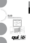
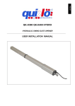
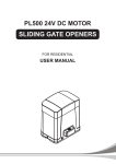
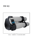
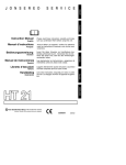
E
N
G
L
I
S
H
use and
ma
i nt
I
T
A
L
I
A
N
O
en
em
an
ute
nzione
ual
man
ce
an
’u s
d
e
l
manua
MOOVY
AUTOMATIONS FOR SLIDING GATES
AUTOMAZIONI PER CANCELLI
SCORREVOLI
MOOVY
o
AUTOMATIONS FOR SLIDING GATES
USE AND MAINTENANCE MANUAL
Dimensions: a=height; b=length; c=width
1- BEFORE INSTALLING THE AUTOMATION
Before installing the automation, you must check that:
- The wheels of the gate are attached to make the gate stable and must be in good condition;
- The entire length of the fixed rail must be free of obstacles, straight and clean and have stoppers at the
ends;
- The upper guide, must be parallel to the rail and lubricated, and it must allow for a clearance of about 1
mm from the door
Borinato F.lli Snc is liable only for products it manufactures and commercializes. Once automated, the gate
becomes a machine and is therefore subject to the rules of the “ Machinery Directive”. It is on the installer to verify
its security. WARNING: Borinato F.lli Snc is not liable for any damages to people, animals or things due to
unauthorised modifications, alterations or betterments on its products by third parties.
E
N
G
L
I
S
H
2- MATERIALS FOR INSTALLATION
FIG. 1
1.
2.
3.
4.
5.
Gearmotor
Counterplate
Limit switches brackets (cammes)
M4 rack
M10 Anchor bolts
3- POSITIONING THE COUNTERPLATE
Dig a concrete foundation base following measurements shown on fig. 2, 3. Position the counterplate making
sure it is perfectly levelled and smooth and complying with the measurements shown on fig. 2, 3. Route the
conduits through the base holes and let them come out for at least 25 cm. If a concrete foundation base is
already available, do not unfold the anchor leaves and fasten the base only with the anchor bolts.
4- POSITIONING THE GEARMOTOR
Drill two holes ø 10 mm on the concrete in correspondence of the holes of the counterplate. Install the
anchor bolts and fasten to the concrete. Remove the gearmotor removable cover. Position the gearmotor
onto the counterplate. Temporary fasten the gearmotor to the base by tightening the anchor bolt nuts. !The
gearmotor position can be adjusted horizontally of approx. 15 mm
If the anchor bolts are not available it is possible using 2 bolts M10x25. The head of the bolts shall be tack
welded to the base plate before the couterplate is embedded on the concrete
5- INSTALLING THE RACK
Use a M4 Rack. Release the gearmotor and set the gate in the open position. Place the rack on pinion
leaving at least 2 mm of gap between the gear teeth. Fasten the rack to the gate in such manner that the
bolts are in the middle of the rack slots (in this way it shall be possible adjust in the future the right gap
between the rack and pinion). Move the gate manually to secure all rack pieces along its full length. Once
the rack has been installed, finally check the gap of 2 mm between the pinion and the rack. Finally secure
the gearmotor with the nuts.
3
FIG. 3
4
E
N
G
L
I
S
H
FIG. 4
6- POSITIONING THE LIMIT SWITCHES BRACKETS (CAMMES)
FIG. 5
Manually position the gate completely open and fasten the limit switch brackets (1) (2) onto the rack so that
the limit switch lever exceeds the length of the brackets by approximately two/thirds. Repeat the operation
with gate completely closed. Provide power and carry out some opening and closing operations (see control
board user manual). Adjust the limit switch brackets so that the gate stops approximately 20 mm before the
opening and closing stops.
5
7- UNLOCKING THE MOTOR MANUALLY
FIG.6
RELEASE INSTRUCTION
In case of fault or power failure, insert the key in the lever lock and turn it of 90°CW. Pull and turn the lever
approx. 90°until it stops and the gate move manually.
! WARNING: perform locking and lock release operations with motor cut off.
LOCK INSTRUCTION
To re-lock the gearmotor, return the lever in closed position and lock it and take the key away.
8- ADJUSTING THE CLUTCH (ONLY FOR QK-M1500 AND QK-M2000 MODELS)
FIG. 7
With a spanner turn the adjusting bolt:
CCW for reducing the gate thrust
CW for increasing the gate thrust.
! THE GATE THRUST SHALL BE ADJUSTED ACCORDING TO THE EN 12453 and 12455.
6
E
N
G
L
I
S
H
9- TYPICAL INSTALLATION
FIG. 9
CONNECTIONS CABLES
1
2
3
4
6
5
7
8
POWER SUPPLY
TX PHOTOCELL ON POST
RX PHOTOCELL ON POST
TX PHOTOCELLS
RX PHOTOCELLS
KEY SELECTOR
FLASHING LAMP
AERIAL
Cables section sqmm
3x1,5
2x0,75
4x0,75
2x0,75
4x0,75
3x1
2x1
RG59
FOR THE ELECTRICAL CONNECTIONS REFER TO THE USER MANUAL OF THE CONTROL BOARD
7
GENERAL ADVICE
Install a gate’s safety system that complies with current regulations. Choose short routes for cables and keep
power cables separate from control ones. Install the control card in a waterproof box. Please refer to current
regulations when setting the gear motor’s maximum torque. We advice you to install an outdoor switch, in
compliance with European standards on the issue of safety, to turn the electricity off when servicing the gate.
Check that each single installed device is efficient and effective. Affix easily readable signs warning about
the presence of a motorised gate.
USE
It is absolutely forbidden to use the device for any other purposes. The installed electronic unit (which must
have built-in electric friction), allows to select the following functions:
automatic: one control impulse will open or close the gate;
semi-automatic: one control impulse will open or close the gate.
In case of a blackout, manual operation is possible by activating the unlocking device.
Having an automatic and electric power device requires special attention in a few situations:
-
not to touch the device with wet hands and/or wet or bare feet;
to turn off electricity before opening the control box and/or actuator;
not to pull the lead to pull the plug out;
to put the gate in movement only when it is completely visible;
to keep out of the gate’s range of action if it is moving. Wait until it has stopped;
not to let children or animals play near the gate;
not to let children use the remote control or other operating devices;
to carry out routine maintenance;
in case of failure, to turn off electricity and operate the gate manually only if it is
possible and safe. Refrain from touching the gate and call an authorised technician.
MAINTENANCE
The MOOVY SERIES geared motors are manufactured for long-term use. Nonetheless, their normal
operation can be compromised by the conditions of the gate; therefore, we will list some operations to keep
the gate efficient.
Warning: Non-specialized staff cannot operate the gate during maintenance. You are advised to cut the
network power in order to avoid accidents or shocks. If the power must be on for various inspections, you
are advised to check and/or deactivate any possible control devices (remote controls, keyboards, etc…)
except for the devise used by the maintenance operator.
Routine maintenance
Each of the following operations must be done when needed and in all cases at least every 6 months:
Gate
!
!
Lubricate the gate’s sliding wheels;
Check the cleanliness and air-tightness of the rack.
Automation System
! Check the operation of the safety devices (photo-cells, ribs, torque limiter) using the methods
described by the suppliers
Extraordinary Maintenance
If special maintenance is required for mechanical parts, you are advised to send the
gear motor out for repairs to be performed by the technicians at the manufacturer.
8
DECLARATION OF COMPLIANCE
(by the installer)
The undersigned:
Address:
in charge of the set-up, declares that the product:
Gate type:
Location:
are in compliance with the essential safety requirements of the regulations:
!
!
!
!
Regulation 89/392CE on Machinery and its subsequent amendments;
EMC Regulation 89/336/CE (Legislative Decree 615/96);
BT Regulation 73/23/CE e 93/68/CE (Legislative Decree 626/96);
CE Machinery Directive 98/37 and directive 93/68/CE-72/23/CE-92/31/CE;
and also declares that the related and/or specific national technical regulations have been
followed:
!
!
!
!
EN 12453/EN 12445 on Industrial, Commercial and Residential Gates and Doors – Safe
Use of Motorized Doors – Requirements and Classification – Test Methods;
EN 12604/ EN 12605 on Industrial, Commercial and Residential Gates and Doors –
Mechanical Aspects – Requirements and Classification – Test Methods;
CEI 64/8 Electrical Systems Using Nominal Tension Not Higher Than 1000V a.c. and 1500
V d.c.;
EN 13241-1 (Industrial, commercial and garage doors and gates), conformity evaluation
(6.3).
Notes:
Place and date: ………………………………………
10
E
N
G
L
I
S
H
11
man
ua
le
I
T
A
L
I
A
N
O
d
s
’u
oe
te
manu nzione
MOOVY
AUTOMAZIONI PER CANCELLI SCORREVOLI
MOOVY
AUTOMATIONS FOR SLIDING GATES
USE AND MAINTENANCE MANUAL
Dimensioni: a=altezza; b=lunghezza; c=spessore
1- PRIMA DELL’INSTALLAZIONE
Prima di procedere all’installazione dell’automazione occorre verificare che:
- Le ruote del cancello siano montate in modo da rendere stabile il cancello, e che siano in buono
stato;
- La rotaia di scorrimento sia libera, diritta e pulita su tutta la sua lunghezza e con battute di arresto
alle estremità;
- La guida superiore sia in asse con la rotaia, sia lubrificata e consenta un gioco di circa 1 mm all’anta;
Si ricorda che Borinato F.lli Snc è responsabile solo degli articoli che produce e commercializza. II cancello, una
volta automatizzato, diventa un macchinario ed è quindi soggetto alle norme della Direttiva Macchine. E' quindi
compito dell'installatore verificarne la sicurezza. ATTENZIONE: Borinato F.lli Snc non risponde di eventuali
danni a persone, animali o cose derivanti da modifiche, alterazioni o migliorie apportate arbitrariamente da
terzi ai suoi prodotti.
2- MATERIALI PER L’INSTALLAZIONE
I
T
A
L
I
A
N
O
FIG. 1
1.
2.
3.
4.
5.
Motoriduttore
Piastra di fondazione
Coppia di finecorsa (camme)
Cremagliera modulo 4
Coppia di Tasselli M10 (o Bulloni M10x25)
3- POSIZIONAMENTO DELLA PIASTRA DI FONDAZIONE
Predisporre uno scavo delle dimensioni illustrate nelle Fig. 2- 3 ed eseguire il riempimento con calcestruzzo.
Posizionare la piastra di fondazione perfettamente orizzontale rispettando le distanze indicate nelle fig.2 -3.
Posizionare i cavi negli appositi fori predisposti lasciandoli fuoriuscire di circa 25 cm dalla base. Se la
fondazione è già predisposta posizionare la piastra senza piegare le due linguette e fissarla al calcestruzzo
mediante I due tasselli ad espansione.
4- POSIZIONAMENTO DEL MOTORIDUTTORE
Eseguire due fori ø 10 mm sul calcestruzzo in corrispondenza dei fori ø 12 della base. Inserire i due tasselli
ad espansione ed ancorarli al calcestruzzo lasciando fuoriuscire la parte filettata di circa 20 mm. Togliere il
coperchio del motoriduttore. Posizionare il motoriduttore sulla base e fissarlo temporaneamente con i due
dadi dei tasselli. !La posizione del motoriduttore può essere regolata orizzontalmente di circa 15 mm.
Se I tasselli non sono disponibili possono essere utilizzati due bulloni M10x25 che devono però essere
saldati alla piastra di fondazione prima della posa della stessa
5- INSTALLAZIONE DELLA CREMAGLIERA
Utilizzare una cremagliera M4. Sbloccare il motoriduttore (ved. Fig. 6). Posizionare il primo pezzo di
cremagliera orizzontalmente sopra il pignone lasciando un gioco di 2 mm tra i denti (Fig. 3). Fissare la
cremagliera al cancello con apposite viti in corrispondenza della mezzeria delle asole. (In questa maniera
sarà poi possibile regolare in maniera precisa il gioco tra I denti della cremagliera /pignone). Muovere il
cancello manualmente e completare il montaggio della cremagliera. A montaggio ultimato controllare il gioco
tra I denti e fissare definitivamente la cremagliera.
15
FIG. 3
16
I
T
A
L
I
A
N
O
FIG. 4
6- POSIZIONAMENTO DELLE CAMME FINECORSA
FIG. 5
Posizionare le camme finecorsa come in fig. 5 e ciascuna vicino ad un estremo della cremagliera. Portare
manualmente l’anta in posizione completamente aperta e fissare le staffe finecorsa sulla cremagliera in
modo che il finecorsa superi per circa i due/terzi la lunghezza della staffa. Ripetere l’operazione con l’anta
completamente chiusa. Dare alimentazione ed eseguire alcune manovre di apertura e chiusura (vedere le
istruzioni di avviamento contenute nel manuale di installazione della centralina di comando). Regolare la
posizione del finecorsa in modo che il cancello si fermi circa 20 mm prima delle battute di apertura e
chiusura.
17
7- SBLOCCO MANUALE
FIG.6
Per le manovre di emergenza (black out) e nelle fasi di installazione del motoriduttore occorre procedere allo
sbloccaggio dell’albero di uscita come segue: inserire la chiave in dotazione nella serratura posta nella leva
di sbloccasggio e ruotare la chiave di 90°in senso orario. Estrarre e ruotare la leva di sblocco fino alla
posizione di arresto. Per il blocaggio procedere in maniera inversa.
8- REGOLAZIONE FRIZIONE MECCANICA (SOLO PER I MODELLI QK-M1500 E QK-M2000)
FIG. 7
Per regolare la forza di spinta sul cancello procedure come in fig. 7.
Con una chiave ruotare la vite posta alla sommità del motore:
In senso antiorario per ridurre la forza (-)
In senso orario per aumentare la forza (+)
18! La forza di spinta deve essere regolata in accordo alle norme EN 12453 and 12455.
9- IMPIANTO TIPO
I
T
A
L
I
A
N
O
FIG. 9
Cavi di collegamento
1
2
3
4
6
5
7
8
Alimentazione Motoriduttore
Collegamento Fotoc. Trasmitt. Su Colonnina
Collegamento Fotoc. Ricevente. Su Colonnina
Collegamento Fotoc. Trasmittente
Collegamento Fotoc. Ricevente
Selettore a chiave
Lampeggiante
Antenna
Sezione cavi
3x1,5
2x0,75
4x0,75
2x0,75
4x0,75
3x1
2x1
RG59
PER I COLLEGAMENTI ELETTRICI FAR RIFERIMENTO AL MANUALE DELLA CENTRALE DI
COMANDO
19
RACCOMANDAZIONI DI CARATTERE GENERALE
Integrare la sicurezza del cancello conformemente alla normativa vigente. Scegliere percorsi brevi per i cavi e
separare i cavi di potenza dai cavi di comando. Effettuare una corretta messa a terra dell’impianto. Per la
messa a punto della coppia massima del motoriduttore, attenersi alle normative in vigore (UNI 8612). In
accordo con la normativa europea in materia di sicurezza, si consiglia di inserire un interruttore esterno per
poter togliere l’alimentazione in caso di manutenzione del cancello.
Verificare che ogni singolo dispositivo installato sia efficiente ed efficace. Affiggere cartelli facilmente leggibili
che informino della presenza del cancello motorizzato.
USO
È severamente vietato l’utilizzo dell’apparecchio per scopi diversi o in circostanze diverse da quelle
menzionate.
La centralina elettronica presente nei motoriduttori permette il funzionamento in 2 differenti modalità:
automatico: l’impulso di comando esegue apertura e chiusura del cancello;
semiautomatico: l’impulso di comando esegue l’apertura o la chiusura del cancello.
Nella condizione di mancata energia elettrica è possibile
il passaggio alla gestione manuale agendo prima sul dispositivo di sblocco.
La presenza di un dispositivo automatico e di corrente elettrica comporta una particolare attenzione verso
alcune situazioni:
! non toccare l’apparecchio con mani e/o piedi bagnati o nudi;
! disinnestare la corrente in caso di apertura della scatola comandi e/o del riduttore;
! non tirare il cavo di alimentazione per staccare la presa di corrente;
! mettere in movimento il cancello solo quando è completamente visibile;
! tenersi fuori dal raggio di azione del cancello se questo è in movimento: aspettare fino a che non sia
fermo;
! non lasciare che bambini o animali giochino in prossimità del cancello;
! non lasciare che bambini usino il telecomando o altri dispositivi di azionamento;
! effettuare una manutenzione periodica;
! in caso di guasto, togliere l'alimentazione e gestire il cancello manualmente solo se possibile e sicuro.
Astenersi da ogni intervento e chiamare un tecnico autorizzato.
.
20
DICHIARAZIONE DI CONFORMITA’
(da parte dell’installatore)
Il sottoscritto: ________________________________________________________________________
Indirizzo:
________________________________________________________________________
in qualità di responsabile della messa in funzione dichiara che il prodotto:
Tipologia
_________________________________________________________________________
Ubicazione:
____________________________________________________________________
è conforme ai requisiti essenziali di sicurezza delle direttive:
Direttiva Macchine 89/392CE e successive modificazioni;
Direttiva EMC 89/336/CE (D.Lgs 615/96);
Direttiva BT 73/23/CE e 93/68/CE (D. Lgs 626/96);
Direttiva Macchine 98/37 CE e direttive 93/68/CE-72/23/CE-92/31/CE;
inoltre dichiara che sono state applicate le norme armonizzate e/o le norme specifiche tecniche nazionali:
EN 12453/EN 12445 Cancelli e porte industriali commerciali e residenziali – Sicurezza nell’uso delle porte
motorizzate – Requisiti e classificazione – Metodi di prova;
EN 12604/ EN 12605 Cancelli e porte industriali commerciali e residenziali – Aspetti meccanici – Requisiti e
classificazione – Metodi di prova;
CEI 64/8 Impianti elettrici utilizzatori a tensione nominale non superiore a 1000V c.a. e 1500 V c.c.;
EN 13241-1 (Porte e cancelli industriali, commerciali e da garage), valutazione di conformità (6.3).
Luogo e data: ________________________
22
Timbro e firma
I
T
A
L
I
A
N
O
23
1095 Budapest, Mester u. 34.
Tel.: *218-5542, 215-9771, 215-7550,
216-7017, 216-7018 Fax: 218-5542
Mobil: 30 940-1970, 20 949-2688
1141 Budapest, Fogarasi út 77.
Tel.: *220-7940, 220-7814, 220-7959,
220-8881, 364-3428 Fax: 220-7940
Mobil: 30 531-5454, 30 939-9989
E-mail: [email protected] Web: www.delton.hu
www.kaputnyitunk.hu
The Manufacturer can technically improve
the quality of its products without
any prior notice.
Il Fabbricante può apportare ai suoi prodotti