1
hands-onproject Programmable analog
10
10
5
0
0
⫺5
⫺10
⫺10
⫺20
⫺15
⫺20
dBV
dBr
A
⫺25
⫺30
⫺30
⫺40
⫺35
⫺50
⫺40
⫺45
⫺60
⫺50
⫺70
⫺55
⫺60
⫺80
⫺65
⫺70
20
50
100
200
500
1k
2k
5k
10k
20k
40k
⫺90
⫺60
⫺50
Hz
⫺40
⫺30
⫺20
⫺10
0
dBV
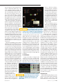
The biquadratic filter CAM allows you to program the
corner frequency, gain, and Q. The bandpass-filter
plots correspond to an 8-kHz corner frequency at Qs of 0.2 (green), 1
(cyan), 5 (blue), and 20 (magenta).
Figure 4
10
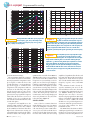
⫹N plots suggest that the input cell’s antialiasTHD⫹
ing filters can limit the useful dynamic range for a
⫹N criterion, particularly if the signal bandwidth approaches
given THD⫹
the filter corner. Here, the 1-kHz (green) and 20-kHz (blue) plots taken
with the antialiasing filters off are congruent. The 1-kHz (magenta) and
20-kHz (red) plots taken with the filter corner set to 34 kHz show
degradation, particularly with signals approaching the corner frequency.
Figure 5
0
⫺10
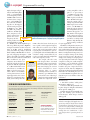
Fixed-amplitude spectral sweeps help fill in Figure
5’s message: Here, the blue plot shows a 0-dBV
sweep without the antialiasing filter. The red plot shows the same input
sweep with the antialiasing filter set to 400 kHz. Reducing the input
amplitude to ⫺6 dBV and noting that the plot’s amplitudes are relative
to the input amplitude, the magenta plot suggests that the filter’s
⫹N degrades across the spectrum with inputs exceeding several
THD⫹
hundred millivolts. With the filter’s corner tuned down to 34 kHz, the
⫺6-dBV sweep shows a sharply increasing THD⫹
⫹N trend in the passband’s last decade.
⫺20
dBr
A
Figure 6
⫺30
⫺40
⫺50
⫺60
⫺70
⫺80
⫺90
20
50
100
200
500
1k
2k
5k
10k
20k
40k
Hz
gram the threshold voltage.
Like most FPAA CAMs, the comparator is a synchronous discrete-time block.
You can program the comparator to sample its inputs on either the first or the
second clock phase—a concept that simply doesn’t apply to continuous-time
comparators. The comparator makes its
decision on the following clock phase,
but the decision may not cause an immediate change in the comparator’s output state. You can program the output to
either follow the decision as soon as it is
available or force it to synchronize the
state transition with either the first or the
second clock phase.
Comparators and amplifiers are the
simplest CAMs, with close analogies in
the world of discrete ICs. Also common
in the CAM list are functions that offer a
higher level of abstraction, moving you
somewhat further away from the implementation details. One example, the bi-
44 edn | June 12, 2003
quadratic filter is tunable from 500 Hz to
400 kHz in three ranges corresponding to
your selection from three available clock
frequencies. As you would expect of a biquad, you can select lowpass, highpass,
bandpass, and bandstop transfer functions. But unlike the biquads you make
yourself from several op amps and a fistful of resistors, the biquad CAM provides
only one of the four transfer functions at
a time. The tuning and Q controls are
noninteractive, but, not surprisingly, your
choice of Q from 0.15 to 70 (!) does limit the gain range (Figure 4).
THE PLOTS THICKEN
Some of the less common functions
might hold the true power of an FPAA,
such as the multiplier or arbitrary periodic waveform-generator CAMs. However, to get a sense of how well the device
works as a signal-chain element, I examined less exotic CAMs, such as inverting
amplifiers, biquadratic filter blocks, and
basic I/O cells. Most of this investigation
employed an Audio Precision System
Two Cascade dual domain analyzer for
frequency response, noise, and THD
plots.
The evaluation board is clearly designed to maximize your access to the
various facilities it offers. It is, therefore,
not optimized for minimum clock noise
(see sidebar “Finding the baseline”).
Though some care may be necessary
when developing applications that make
full use of the FPAA’s bandwidth, which
extends to about 8 MHz, the board
should serve as a good development environment with little practical interference from clock artifacts for lowerbandwidth circuits.
The FPAA’s data-sheet limit on differential input signal swings is 3.8V. Be careful, however, if you are going to run your
signals at or near the swing limit. For exwww.edn.com