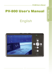
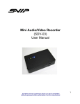
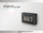
1
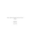
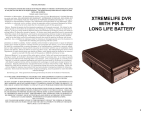
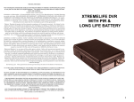
TM
Responder 1000
Quick start will guide you through the
most basic operations and installation.
800.428.4315
Vehicle Dock
www.DecaturRadar.com
1. Connecting
Component Cables
to Vehicle Dock for
a Standard Setup
See your user’s manual
AV Output
for how to properly
ports
connect the Responder
Audio
1000 power harness
to the vehicles power
AV Output
source. The power
ports
harness must be installed
Video
Audio
before the components
can be connected.
Use figure 1 to identify
the vehicle dock ports.
The audio ports are only
used with feature items
not shown in the standard
setup.
1
Use figure 2 to
identify the different
cables and how they
are connected to the
correct port. This
figure shows the
Responder 1000
and components
unmounted, see
your user’s manual
for mounting
instructions. The
Molex connector,
audio cables, and
DB 9 camera cables
all need to be
connected as shown
to achieve the
standard setup.
Vehicle Dock
Telex Audio
ports
Camera
port
Video
Molex
port
Molex
port
Telex Audio
ports
Camera
port
Figure 1 Identifying vehicle dock ports
Power Harness
Shadow 800 DVR
Camera
DB 9
cable
Vehicle Dock
In-vehicle
microphone
Connected Molex
connector
Telex
Connected Molex
cable
Telex audio cable
In-vehicle
radar overlay
port
DB 9 camera cable
connected to camera ports
Connected Telex
audio cables
Connected
in-vehicle
microphone
Connected Telex
DB 9 camera cable
If applicable connect
Connected
audio cables
connected
to camera ports
in-vehicle
In-vehicle
the in-vehicle
microphone
radar
overlay
radar overlay cable to the back of the camera and to the serial port labeled “Radar” on the back
port
of your Genesis II Radar. If applicable connect the in-vehicle microphone to the wireless audio
base.
Place the Responder 1000 DVR into the vehicle dock. When the vehicle ignition is engaged
the Shadow 800 unit should automatically turn on and go into a preview mode displaying a live
camera feed. A recording will not start until the vehicles light bar control switch is activated, the
EMG panic button on the wireless transmitter is pressed, or the record button in pressed on the
DVR or remote. See your user’s manual for how to start/stop a recording and view a playback.
1
TM
Responder 1000
Quick start will guide you through the
most basic operations and installation.
800.428.4315
www.DecaturRadar.com
2. Connecting and
Using Office Dock
2
Use figure 3 to
identify the different
ports used for the
office dock.
Use figure 4 to
identify how the
cables connect to
the office dock.
Thread the B type
USB cable and
AC adaptor ends
through the hole
in the stand and
plug into the dock.
Connect the USB
to your PC USB
port and the
AC adaptor to a
110 VAC power
source. If your
Responder 1000
DVR is in the
vehicle dock
remove it and place
it in the office dock
with your PC on.
Note: the AV output
ports are used with
the AV cables to
connect the unit to
a TV for playback.
Office Dock Removed from Stand
AV Output
ports
Office Dock Removed from Stand
Audio
AV Output
ports
Audio
Video
B type USB
port
AC power
adaptor port
Video
B type USB
port
AC power
adaptor port
Figure 3 Identifying office dock ports
Thread cables
through hole
in stand
Thread cables
through hole
in stand
Connect to PC
USB port
Connect to PC
USB port
Connect to
AC power source
Connect to
When the DVR
AC power source
Connected AC
is placed in the
Connected B type USB
power adaptor
office dock a
Windows dialog
Connected AC
Connected B type USB
box stating that
power adaptor
this disk or device
contains more then one type of content should pop up and ask, “What do you want Windows to
do?” Choose, “Open folder to view files.” If the Windows dialog box does not appear. Go to “My
Computer” in your Windows start menu and look under “Devices with Removable Storage” under
which should appear a drive called “DVR”, double chick the icon. Once the DVR drive has been
opened double click on the “MyRecord” folder. Here you will see the recorded video files the
Responder 1000 system has saved. The files are ready to Move or Cut and Paste to your PC’s
harddrive.
See the back office solution section in your user’s manual for a more detailed discussion on file
transfer and archival.
2