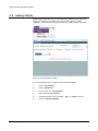
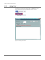
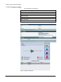
1
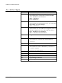
EMS Software Installation and Operation Manual IM02960173 Rev.C Reliability Choice Innovation Copyright Notice All information contained in this Manual are the property of ST Electronics (Satcom & Sensor Systems) Pte. Ltd. The Manual in whole or in part, may not be duplicated or reproduced without the written permission of ST Electronics (Satcom & Sensor Systems) Pte. Ltd. The Manual is intended to be used as a guide only and may be revised, modified or altered at any time by ST Electronics (Satcom & Sensor Systems) Pte. Ltd. ST Electronics (Satcom & Sensor Systems) Pte. Ltd. shall not be liable to users of the Manual nor to any other person, firm, company or other body for any loss, direct, indirect or consequential, in contract or in tort or for any negligent mis-statement or omission contained herein, by reason of, arising from or in relation to any such user, other person, company or body relying or acting upon or purporting to rely or act upon any matter contained in this Manual. If you have any enquiry or require further technical assistance, please contact our Customer Service Centre at: ST Electronics (Satcom & Sensor Systems) Pte. Ltd. No. 29 New Industrial Road, ST Electronics Paya Lebar Building Singapore 536213 Hotline: +65 6521 7959 Fax: +65 65217333 E-mail: [email protected] Website: www.agilissatcom.com © 2011 ST Electronics (Satcom & Sensor Systems) Pte. Ltd. All Rights Reserved. Table of Contents Chapter 1 Product Overview ............................................................................................ 1 1.1 About The EMS ...................................................................................... 1 1.2 Pre-Requisites for Agilis EMS Installation ....................................................... 1 1.3 Definitions, Acronyms & Abbreviations ......................................................... 2 1.4 Device Types ........................................................................................ 3 1.5 Devices Supported by Agilis EMS ................................................................. 4 1.6 Conventions Used................................................................................... 5 Chapter 2 Installation Steps ............................................................................................. 7 2.1 Installation Procedures ............................................................................ 7 2.2 Cable Connection and Pin Configurations......................................................10 Chapter 3 Operational Manual .........................................................................................11 3.1 Getting Started ....................................................................................11 3.2 Main User Interface ...............................................................................13 3.3 Types of Users......................................................................................13 3.4 Color Legend .......................................................................................14 3.5 Features – Menu Bar & Tree View ...............................................................15 3.6 Device Configuration ..............................................................................16 3.7 Features – Control Panel..........................................................................27 3.8 Functions of an Admin User ......................................................................38 3.9 Analog Charts.......................................................................................39 3.10 Debug Tool..........................................................................................40 3.11 Purging Historical Analog and Alarm Data .....................................................41 3.12 Device Setup .......................................................................................42 3.13 Troubleshooting....................................................................................64 3.14 Agilis EMS Equipment Parameters...............................................................66 Appendix A Document Revision Log .....................................................................................69 IM02960173 Rev.C i List of Figures Figure 2.1 Device and PC connection through USB/RS-485 converter ...........................................10 Figure 3.1 Agilis EMS User Interface ...................................................................................13 Figure 3.2 Device Configuration Link ..................................................................................16 Figure 3.3 Device Configuration Window .............................................................................16 Figure 3.4 Communication Settings....................................................................................18 Figure 3.5 Invalid Device Combination Error .........................................................................21 Figure 3.6 Control Panel.................................................................................................27 Figure 3.7 Status button.................................................................................................28 Figure 3.8 Configuration button........................................................................................29 Figure 3.9 Info button ...................................................................................................30 Figure 3.10 Alarm button .................................................................................................30 Figure 3.11 Audible alarm icon ..........................................................................................31 Figure 3.12 Audible alarm icon ..........................................................................................31 Figure 3.13 Switching Mode Configuration Window ..................................................................32 Figure 3.14 Path Selection window .....................................................................................37 Figure 3.15 User Management tab.......................................................................................38 Figure 3.16 Analog Chart window .......................................................................................39 Figure 3.17 Debug Tool window .........................................................................................40 Figure 3.18 BUC Standalone ..............................................................................................43 Figure 3.19 SSPA Standalone .............................................................................................44 Figure 3.20 MBUC Standalone ............................................................................................45 Figure 3.21 iBUC Standalone .............................................................................................46 Figure 3.22 RCU (Rx) Standalone ........................................................................................47 Figure 3.23 RCU Tx Standalone ..........................................................................................48 Figure 3.24 RCU (Tx&Rx)..................................................................................................49 Figure 3.25 SPT Standalone ..............................................................................................50 Figure 3.26 AUC Standalone ..............................................................................................51 Figure 3.27 BUC + SSPA Integrated Mode...............................................................................52 IM02960173 Rev.C ii Figure 3.28 BUC + RCU (Tx) ..............................................................................................53 Figure 3.29 BUC + RCU (Tx&Rx) .........................................................................................54 Figure 3.30 SSPA + RCU (Tx)..............................................................................................55 Figure 3.31 SSPA + RCU (Tx&Rx).........................................................................................56 Figure 3.32 BUC + SSPA + RCU (Tx)......................................................................................57 Figure 3.33 BUC + SSPA + RCU (Tx&Rx).................................................................................58 Figure 3.34 1:1 iBUC.......................................................................................................59 Figure 3.35 LNB + RCU (Rx)...............................................................................................60 Figure 3.36 LNB + RCU (1:2) Rx ..........................................................................................61 Figure 3.37 BUC + RCU (1:2) Tx..........................................................................................62 Figure 3.38 MBUC + RCU (1:2) Tx........................................................................................63 IM02960173 Rev.C iii List of Tables Table 1-1 Definitions of Acronyms ..................................................................................... 2 Table 1-2 Device Types .................................................................................................. 3 Table 1-3 Devices Supported by Agilis EMS ........................................................................... 4 Table 2-1 M&C cable pin signal assignment .........................................................................10 Table 3-1 User Table ....................................................................................................13 Table 3-2 Combination of Devices for each mode ..................................................................17 Table 3-3 Combination of Devices for each mode ..................................................................42 Table 3-4 Equipment Parameters .....................................................................................67 IM02960173 Rev.C iv Chapter 1 Product Overview Agilis, a global leader in the design, development and manufacturing of quality satellite products for various applications, introduces the EMS Software. 1.1 About The EMS Agilis EMS Software is a lightweight network management software that provides monitoring and controlling support for Agilis Products (BUC, MBUC, iBUC, SSPA, LNB, RCU, AUC, SPT and OHT). This user manual provides detailed information to system integrators and end users on how to install, set-up and operate the Agilis EMS Software. This document consists of two sections, Installation and Operational Guide. The procedures indicated in this manual must be followed to ensure the proper functionality of the Agilis EMS Software. 1.2 Pre-Requisites for Agilis EMS Installation 1.2.1 Software Requirements 1. AgilisEMS.exe 2. Windows XP / Windows 7 3. IE 7 or later versions 4. WinZip/Winrar to extract the zip files 5. Acrobat Reader to view the historic data 6. Adobe Flash Player for viewing Agilis EMS control panel 7. ODBC Driver 1.2.2 Hardware Requirements 1. Windows based PC 2. Pentium 4 and above 3. 2GB RAM (Recommended) 4. At least 1GB Hard Disk free space 5. M&C Interface cable ( For pin configurations, refer to respective Product Manuals) IM02960173 Rev.C 1 Chapter 1 Product Overview 1.3 Definitions, Acronyms & Abbreviations Abbreviation Attn Attenuation BUC Block Up Converter Available for two different frequencies: Ku-band (Ku-BUC) and C-band (C-BUC) C-BUC ALB180xxxx C-band Block Up Converter D/C LO Down-Converter Local Oscillator Freq Frequency Global Address An address that will be responded by any ODU, disregarding its assigned address. For Ku-SPT, FC-SPT, EC-SPT, BUC, AUC28 and OHT, the global address is 000. KU-BUC ALB128xxxx Ku-band Block Up Converter LNB Low Noise Block Converter ODU Out Door Unit Could be RCU, Ku-SPT, C-SPT, FC-SPT, EC-SPT, CBUC, Ku-BUC, AUC28 and OHT RCU Redundancy Control Unit SSPA Solid State Power Amplifier or Booster VB Visual Basic HMI Human Machine Interface Table 1-1 IM02960173 Rev.C Description Definitions of Acronyms 2 Chapter 1 Product Overview 1.4 Device Types Abbreviation Description BUC FM-Integrated – Feedmount-Integrated BUC (<80W) These models have a single BUC RF module and M&C. CBUC – ALBx80xxxx and ALBx90xxxx KuBUC – ALBx28xxxx XBUC – ALBx50xxxx MBUC FM-Modular – Feedmount-Modular BUC (<80W) These models have modular BUC driver and a separate SSPA module in a single package. KuBUC – ALBx29xxxx iBUC Integrated RCU BUC – These models are with additional integrated RCU and redundant capable (for Hi-Pwr BUC, 80W and above) CBUC – ALBx80xxxx and ALBx90xxxx KUBUC – ALBx28xxxx and ALBx29xxxx iBUC-RM Integrated RCU BUC - Rack Mount SSPA Sold‐State‐Power‐Amplifier These models are C-Band and Ku-Band RF Boosters AAAxxxxxxx LNB Low Noise Block Converter RCU Redundancy Control Unit These models are External Redundancy Controllers for 1+1 and 2+1 systems. AAV61xxxxx and AAV62xxxxx RCU (1:2) RCU (Rev 2) AUC Agilis-Up-Convertor Indoor SPT Single-Package-Transceiver OHT One-Housing-Transceiver Table 1-2 IM02960173 Rev.C Device Types 3 Chapter 1 Product Overview 1.5 Devices Supported by Agilis EMS BUC iBUC SSPA LNB ALBX28XXXXXXXXX-X ALBX28-XX AAAXXXXXXXX-X ACAXXXXXXX-X ALBX80-XX AAAxxxxxxxM ACAXXXXXXX-XX ALB1282X ALB1283X RCU AUC SPT OHT AAV610X-T AUC2840X AAVXXXXXXXX AAV980XXXXX -X AAV610X-R AUC284LX ALBX29XXX -XX AUC284KX ALB1285X ALB128xxxxVO ALB180AX AUC285LX AUC38XXX XXX-X AUC68XXX XXX-X ALB180BX ALB180CX ALB180FX ALB180xxCx Table 1-3 Devices Supported by Agilis EMS *Note: if the RCU is a legacy version, the following has to be done: i) Go to this folder: Agilis EMS \Driver\Configurations\Factory\Legacy ii) Copy the 2 files: rcu_tx_config.xml and rcu_tx_protocol.xml iii) Replace the 2 files in this folder: Agilis EMS\Driver\Configurations\Factory iv) Copy of the new version is found in this folder: Agilis EMS \Driver\Configurations\Factory\New Hence, the files can be replaced back when necessary. IM02960173 Rev.C 4 Chapter 1 Product Overview 1.6 Conventions Used The following icons/fonts are used in this document: : Points to take note of. : Warning! Failure to adhere to the warnings may result in adverse effects. Italics: Notes BOLD: Elements that require human intervention to be executed or names of main options. ‘BOLD’: Agilis EMS options in bold text within quotes. IM02960173 Rev.C 5 Chapter 1 Product Overview ---This page is intentionally left blank--- IM02960173 Rev.C 6 Chapter 2 Installation Procedures This chapter provides information on how to install the Agilis EMS software in the user PC. Cable connections and pin configurations are also covered in this chapter. 2.1 Installation Steps IM02960173 Rev.C 1. Navigate to the folder where the ‘AgilisEMS.exe’ is located. 2. Click on ‘AgilisEMS.exe’ to run the installation. 3. Click ‘Next’. 4. Click ‘Next’. 7 Chapter 2 Installation Procedures 5. It is advisable to leave the Destination Folder as it is, C:\Agilis EMS. DO NOT select paths that have spaces in between such as (Program Files). 6. Click ‘Next’. 7. If the destination folder does not exist, a pop-up window will prompt to create the folder. Click ‘Yes’ to continue. 8. IM02960173 Rev.C Click ‘Start’. 8 Chapter 2 Installation Procedures 9. Installation process would be initiated. 10. Click ‘Exit’ to complete the installation. 11. Verify that the folder Agilis EMS has been created in C:\. 12. The following 3rd party applications should be installed before launch Agilis EMS application, Adobe Reader, Flash Player and ODBC driver. 13. To uninstall the software, simply click on Uninstall Agilis EMS from Start > All Programs > Agilis EMS. If the 3rd party applications were already installed, you would be prompted that you are having the latest, therefore click on the prompts as required cancelling the installation. IM02960173 Rev.C 9 Chapter 2 Installation Procedures 2.2 Cable Connection and Pin Configurations All Agilis devices support RS485 communication. When the product is communicating on RS-485, a USB to RS485 converter is needed to connect the Agilis device to a PC, as shown in Figure 2.1. Figure 2.1 Device and PC connection through USB/RS-485 converter The driver for the RS485 to USB converter must be installed to establish serial communication between the device and the PC. 2.2.2 RS-485 M&C Cables The table below indicate the pin signal assignment of the M&C cables used for different types of Agilis devices. No Female Circular (19-pin and 8-pin) Female DB-9 Signal Description 1 Pin E 2 Data + 2 Pin F 1 Data - 3 Pin B 5 Ground Table 2-1 IM02960173 Rev.C M&C cable pin signal assignment 10 Chapter 3 EMS Operations Manual This chapter provides information on how to use and configure the Agilis EMS software. 3.1 Getting Started To Launch the Agilis EMS Software, click on Start > All Programs > Agilis EMS, click on the Launch Agilis EMS to start Agilis EMS. Once all the required services are started, an Agilis icon would be displayed in the notification area usually found in the bottom right hand corner. This would indicate that the startup of services has been initiated. An IE (Internet Explorer) window will automatically pop-up upon successful startup. IM02960173 Rev.C 11 Chapter 3 EMS Operations Manual 3.1.1 Exiting the application If the Agilis EMS application needs to be stopped, follow these steps: IM02960173 Rev.C 1. Right click on the Agilis icon and select ‘Exit’. 2. Click ‘Yes’ to confirm program exit. 3. Close the IE browser displaying the EMS Software. 12 Chapter 3 EMS Operations Manual 3.2 Main User Interface Figure 3.1 Agilis EMS User Interface 3.3 Types of Users By default, the current user is an Operator (Guest) with no administrative rights. The table below would summarize the types of user, password details and their rights. User Operator (Guest) admin Table 3-1 Password NA admin Options Available Analog Charts Device Configuration Analog Charts Device Configuration User Management User Table The user logged in as an ‘Operator’ can use the ‘Device Configuration’ but can only see the device configuration changes after exiting and re-launching the Agilis EMS application. IM02960173 Rev.C 13 Chapter 3 EMS Operations Manual 3.4 Color Legend The following color conventions are used to indicate the status of the equipment. The conditions are tabulated below. Do take note that the RF Input is always showed as Green. Device Name Condition Color Convention Possible Condition Alarm Offline Equipment is not connected or switched ON Online No Alarms Present Major Alarm - BUC (Stand Alone) - BUC FET Bias Alarm BUC LO Alarm BUC Temperature Alarm BUC RF Output Alarm BUC 10 MHz Reference Alarm BUC Driver Alarm SSPA Temperature Alarm SSPA Reflected Power Alarm SSPA RF Output Power Low Alarm Minor Alarm - Signal Up RF ON Signal Down RF OFF The color convention applies to all the devices supported by Agilis EMS but alarms may differ. Refer to ‘Table 3-4 Equipment Parameters’ to view the complete list of Alarms. IM02960173 Rev.C 14 Chapter 3 EMS Operations Manual 3.5 Features – Menu Bar & Tree View The Tree View is a vertically expandable menu found on the left hand side of the webpage. The Tree View can be hidden as well if not required. The Show/Hide Tree View option is found on the Menu Bar. The Menu Bar options would dynamically change according to the user logged in. The information about the dropdown list of the Menu Bar can be found in Table 3-1 ‘User Table’. Each time a device configuration is added, it is displayed in the Tree View. Clicking on the ‘-’ sign would collapse the Port while the ‘+’ sign would expand the Port to reveal the status of the devices configured. The status is color coded and it is the same as reflected in the Legend table shown in the Control Panel. Clicking on the ‘Device Management System’ would refresh the Tree View. IM02960173 Rev.C 15 Chapter 3 EMS Operations Manual 3.6 Device Configuration Device configuration allows the user to add/configure equipment that needs to be monitored and controlled. The option is accessible from the top menu namely ‘Administration’ > ‘Device Configuration’. A new window will pop up when the ‘Device Configuration’ option is clicked. Figure 3.2 Device Configuration Link Log-in as an administrator to add a new device. Click on ‘Add device configuration’ link on top of the device configuration screen. To update the configuration for an existing device, click on ‘Edit’ link corresponding to the device in the table. To delete the existing monitored device, click on ‘Delete’ link that corresponds to the device in the table. (Refer Figure 3.3). Figure 3.3 Device Configuration Window Always click the ‘Restart Driver’ button after configuring a device for the configuration changes to take effect (Refer to Figure 3.3). Click the ‘Refresh’ button located at the bottom left part of the Agilis EMS IE Window to refresh the display in the window and to see the configuration changes (Refer to Figure 3.2). Screen refresh usually takes about 5-10 seconds after the refresh button is clicked, or if there are changes in the system operation. IM02960173 Rev.C 16 Chapter 3 EMS Operations Manual A new window will pop up when the ‘Add device configuration’ option is clicked. The parameters that can be configured are: 1. Communication Settings 2. Device Settings 3. Acronyms Agilis EMS is capable to monitor and control a ‘Stand Alone’ device (simple transceiver) or ‘Integrated Systems’ or a ‘Redundancy System’ (i.e. 1:1 hot standby system). Each mode has its own combination of devices (Refer to Table 3-2). Standalone Integrated 1:1 BUC BUC+RCU(Tx) SSPA BUC+RCU (Tx&Rx) MBUC MBUC+RCU(Tx) iBUC SSPA+RCU(Tx) RCU (Rx) SSPA+RCU (Tx&Rx) BUC+SSPA+RCU (Tx) BUC + SSPA RCU (Tx) RCU (Tx&Rx) BUC+SSPA+RCU (Tx&Rx) SPT iBUC AUC LNB+RCU(Rx) Table 3-2 1:2 LNB+RCU (Rx) BUC+RCU (Tx) MBUC+RCU (Tx) Combination of Devices for each mode Refer to section ‘3.12 Device Setup’ for the different combination of devices that can be selected on the ‘Setup’ option of the Device Configuration Window. IM02960173 Rev.C 17 Chapter 3 EMS Operations Manual 3.6.2 Communication Settings To monitor the device using COM port, select ‘Serial’ in ‘Protocol’ dropdown and enter the COM port number in the ‘Port’ textbox. Figure 3.4 Communication Settings The driver for the RS485 to USB converter must be installed to establish serial communication between the device and the PC. The examples shown on this document uses Com Port number 3. Follow the procedure below to identify the actual COM port number assigned to your Agilis device. To identify COM Port number, follow these steps: 1. IM02960173 Rev.C Right click ‘Computer’, and select ‘Properties’. 18 Chapter 3 EMS Operations Manual 2. Click ‘Device Manager’. 3. Double-click ‘Ports (COM & LPT)’ and take note of the Port number assigned to the device. To change the ‘Baud Rate’ settings click on the drop down button and choose from the drop down list (Refer to Figure 3.4). To monitor the device using Ethernet port, click on ‘Protocol’ dropdown and select ‘UDP’ and enter details in ‘PC IP’ and ‘HUB IP’. IM02960173 Rev.C 19 Chapter 3 EMS Operations Manual 3.6.3 Device Settings Device settings option allows the user to choose the device, operational mode and RCU type of the equipment that you want to monitor. Agilis EMS supports standalone mode, redundant mode and integrated mode. The device configuration settings must be properly set to enable the Agilis EMS application to communicate with the Agilis device, otherwise, no communication between the PC and the device will be established. When selecting a device on the ‘Setup’ list, a text box will appear temporarily to provide a description of the device being selected. 3.6.3.1 Standalone Mode Select ‘Standalone’ mode in the dropdown list and click on the device that you want to monitor in ‘Setup’ list box. When the RCU device is selected, ‘RCU type’ dropdown will show on the screen to select Transmit and Receive Modes. For users who want to connect both transmitter and receiver units or just connect one of the two parts they can choose modes from this dropdown. IM02960173 Rev.C 20 Chapter 3 EMS Operations Manual 3.6.3.2 1:1 Redundancy Mode In redundancy mode, Agilis EMS uses one specific port to monitor and control the combined devices in this mode. Select ‘1:1’ mode in the dropdown list and Click the device that you want to monitor in ‘Setup’ list box. (Refer to Table 3-2 for the valid combinations.) To select multiple items, hold CTRL and Click the devices in ‘Setup’ list box. An error will appear when the user clicks ‘Add/Edit’ on the Device Configuration Window if the combination of devices is invalid. Figure 3.5 Invalid Device Combination Error When the RCU device is selected, ‘RCU type’ dropdown will show on the screen to select Transmit and Receive Modes. For users who want to connect both transmitter and receiver units or just connect one of the two parts they can choose modes from this dropdown. Address Initialization should be done for redundancy program to function. To initialize the addresses, (Refer to section 3.7.7 ‘Init Address’). IM02960173 Rev.C 21 Chapter 3 EMS Operations Manual 3.6.3.3 Integrated Mode Select ‘Integrated’ mode in the dropdown list and select ‘BUC’ and ‘SSPA’ in ‘Setup’ list box. To select multiple items, hold CTRL and Click the device in list box. 3.6.4 Acronyms Acronyms allow the user to choose the title for the selected equipment. In Acronyms text box, special characters are not allowed except the – [hyphen] symbol. IM02960173 Rev.C 22 Chapter 3 EMS Operations Manual 3.6.5 Saving the Device Configuration Settings To save the device configuration settings, click on ‘Add/Edit’ button. Table will be updated with the new/updated device setting in device configuration screen. Changes will take effect only after the ‘Restart Driver’ is clicked (Refer to Figure 3.3). Click the ‘Refresh’ button shown to Figure 3.2, to refresh the Agilis EMS Window. In Agilis EMS main screen, the tree view will show the new device configuration identified by the port number. If the changes are not reflected after the ‘Restart Driver’ and ‘Refresh’ is clicked, restart Agilis EMS application. Refer to ‘3.1.1 Exiting the application’ and re-launch the Agilis EMS Software after 5-10 seconds. When a new device is connected and identified, the device has to be initialized for the first time only. IM02960173 Rev.C 23 Chapter 3 EMS Operations Manual 3.6.6 Example: Configuring a Standalone BUC 1. Login as an ‘admin’. 2. Click ‘Device Configuration’ under the Administration option in the Menu Bar. 3. Click on the ‘Add device configuration’ option in the Device Configuration window. IM02960173 Rev.C 24 Chapter 3 EMS Operations Manual 4. Configure the Communication Settings. For this example, the Protocol used is ‘Serial’, the COM Port assigned is 3 and the Baud Rate is 9600. The COM Port used for the examples in this document is 3. Refer to section ‘3.6.2 Communication Settings’ to identify the specific port assigned to your Agilis device. 5. Configure the Device Settings. For this example, the Mode selected is ‘Standalone’ and the device selected on the Setup list is ‘BUC (FeedmountIntegrated)’. The ‘Acronyms’ used in this example is the default ‘BUC-1’. Refer to section ‘3.12 Device Setup’ for the Device Settings information. 6. IM02960173 Rev.C Click ‘Add/Edit’ button. 25 Chapter 3 EMS Operations Manual 7. Click ‘Restart Driver’ for the changes to take effect. 8. Click ‘Refresh’ to refresh the display on the Agilis EMS main window. The Tree Menu should display the newly configured device along with the port number. 9. The block diagram of the newly configured device will now be displayed on the Agilis EMS main window. IM02960173 Rev.C 26 Chapter 3 EMS Operations Manual 3.7 Features – Control Panel Figure 3.6 Control Panel The control panel, shown in Figure 3.6, is where the status and configuration parameters are read. There are many different combinations of the screen apart from what is shown here. The following are the four main icons located at the right of the control panel: 1. Status 2. Configuration 3. Info 4. Alarms The icons when clicked will refresh the table in the lower part of the control panel. (Refer to Table 3.3 for a more detailed list.). Status IM02960173 Rev.C Device Status, not configurable Configuration Configuration Parameters subjective to equipment type Info Alarms Device Address Device Alarms Model Number Severity Serial Number Timestamp Firmware Version 27 Chapter 3 EMS Operations Manual 3.7.2 Status Click on the ‘Status’ icon to check the device setup of a configured device/combination of devices. User would be able to see all the status parameters in ‘Status Table’. Figure 3.7 Status button IM02960173 Rev.C 28 Chapter 3 EMS Operations Manual 3.7.3 Configuration Click on the ‘Configuration’ icon from the control panel to SET device configuration parameters. To change the values of the device, simply click on the boxes where the present values are being displayed. A new window would pop up for the user to enter/select the desired value. Configuration parameters are subjective to equipment type, as shown on Table 3-4 Equipment Parameters). Figure 3.8 Configuration button IM02960173 Rev.C 29 Chapter 3 EMS Operations Manual 3.7.4 Info Click on the ‘Info’ icon to check the device information. User would be able to see all the device information in ‘Info table’. Figure 3.9 Info button 3.7.5 Alarm Click on the ‘Alarm’ icon to check the existing alarm. User would be able to see all the alarms information in ‘Alarms table’. Figure 3.10 Alarm button IM02960173 Rev.C 30 Chapter 3 EMS Operations Manual Click on the ‘Speaker’ icon on the left hand side of the Agilis EMS (Figure 3.8 and Figure 3.9) to toggle the Audible Alarm. When this feature is enabled, a continuous beeping sound will be heard whenever there’s a major alarm in the system. Figure 3.11 Audible alarm icon Figure 3.12 Audible alarm icon IM02960173 Rev.C 31 Chapter 3 EMS Operations Manual 3.7.6 Mode User would be able to set the switching mode configuration by click on the ‘Mode’ icon. A new window would pop up for the user to enter/select the desired value. The mode icon will not appear in the top menu if the BUC (Standalone), SSPA (Standalone), iBUC (Standalone), BUC+SSPA (Integrated), AUC (Standalone), SPT (Standalone) Figure 3.13 Switching Mode Configuration Window Only applies to redundancy system configurations. 3.7.7 Init Address For Ku-BUC and C-BUC, the address of ODU A is 001 and ODU B is 002. The method of the address-initialization is done by broadcasting a change of ID command. Every device connected to the RS485 bus (except for RCU) will change its address accordingly. Therefore, during the initialization, only the device desired to be have its ID changed (booster with M&C option, etc.) should be connected to the RCU. Please note that in Receiver Only Redundancy Mode “Rx Alone”, the initialize address function is not available, since there are no BUCs or booster physically connected in this mode. There are two types of redundancy system. IM02960173 Rev.C 1. Internal Redundancy Control Unit 2. External Redundancy Control Unit 32 Chapter 3 EMS Operations Manual 3.7.6.1 Configuration steps for internal redundancy control unit. 1. Click on “Init Address” button. 2. A new window would pop up for the user to enter/select the desired value. Select “A” and click ‘OK’. 3. A dialog box would pop up for the user to confirm “Set address of Unit A to 001 and Unit B to 002”. Select ‘OK’. 4. Another dialog box would popup for the user to confirm before initialize the address disconnect the Status link cable between the 2 units. Connect the M&C cable from the PC to the unit to be configured as Unit A. Select ‘OK’. IM02960173 Rev.C 33 Chapter 3 EMS Operations Manual 5. Success message would display after initialize Unit A. To initialize Unit B, Select “B” and click ‘OK’. 6. A new dialog box would pop up for the user to confirm before initialize the address disconnect the Status link cable between the 2 units. Connect the M&C cable from the PC to the unit to be configured as Unit B. Select ‘OK’. 7. Success message would display after initialize Unit B. Click ‘Cancel’ or close the window. Only applies to redundancy system configurations. IM02960173 Rev.C 34 Chapter 3 EMS Operations Manual 3.7.6.2 Configuration steps for external redundancy control unit. 1. Click on “Init Address” button. 2. A new window would pop up for the user to enter/select the desired value. Select “A” and click ‘OK’. 3. A dialog box would pop up for the user to confirm the settings. Select ‘OK’. 4. Another dialog box would popup for the user to confirm before initialize the address connect Unit A to Status A of RCU and disconnect the other ODU form RCU. Select ‘OK’. IM02960173 Rev.C 35 Chapter 3 EMS Operations Manual 5. Success message would display after initialize Unit A. To initialize Unit B, Select “B” and click ‘OK’. 6. A dialog box would pop up for the user to confirm the settings. Select ‘OK’. 7. Another dialog box would popup for the user to confirm before initialize the address connect Unit B to Status B of RCU and disconnect the other ODU form RCU. Select ‘OK’ IM02960173 Rev.C 36 Chapter 3 EMS Operations Manual 8. Success message would display after initialize Unit B. Click ‘Cancel’ or close the window. Only applies to redundancy system configurations. 3.7.8 Path Selection User would be able to configure the Tx Path by click on the ‘Path Selection’ icon. A new window would pop up for the user to enter/select the desired value. Figure 3.14 Path Selection window Only applies to redundancy system configurations. IM02960173 Rev.C 37 Chapter 3 EMS Operations Manual 3.8 Functions of an Admin User When logged is as an Admin user, (login details found in Table 1 – User Table) there are a number of administrative functions that can be done. Under the ‘Administration’ tab found in the menu bar, ‘Device Configuration’, and ‘User Management’ are available. Apart from viewing analog charts and configure device, the admin user is able to add/update/delete the application users. 3.8.1 User Management – Add/Edit/Delete User Figure 3.15 User Management tab The User Management window shown above allows the adding of a new user. Simply, 1. Fill in ‘Username’ field 2. Fill in ‘Password’ field 3. Retype ‘Password’ 4. Fill in ‘Phone Number’ (Optional) 5. Click ‘OK’ to add The new user would be added to the system and the details would be reflected in the User Management table. In order to add another user, click on the ‘Reset’ button before proceeding. To edit a current user, click on the ‘Edit’ option found in the user table of a particular user that needs update. Upon clicking, the user information would be displayed in the textboxes. After editing, click on the ‘OK’ button to save the changes. The updated information of the user would be refreshed in the table. Only User Name and Phone Number are visible. The password field will not be available for viewing. In order to delete a user, click the ‘Delete’ option to execute the deletion of the user. IM02960173 Rev.C 38 Chapter 3 EMS Operations Manual 3.9 Analog Charts Analog charts allow the user to view selected parameters over time in a graph. The option is accessible from the top menu namely ‘Tools’ >‘Charts’. A new window will pop up when the ‘Chart’ option is clicked. Figure 3.16 Analog Chart window To view the status over a period of time, do the following: IM02960173 Rev.C 1. Select ‘Port Number’ 2. Select ‘Equipment’ 3. Enter the device ‘Serial Number’ 4. Select desired ‘Parameters’ 5. Set desired time frame via ‘Hour’, ‘Day’ or ‘Month’ list box 6. Click on ‘Generate Report’ 39 Chapter 3 EMS Operations Manual 3.10 Debug Tool Debug Tool allows the user to monitor the selected port. The option is accessible from the top menu namely ‘Tools’ > ‘Debug Tool’. A new window would pop up when the ‘Debug Tool’ option is clicked. Figure 3.17 Debug Tool window IM02960173 Rev.C 40 Chapter 3 EMS Operations Manual 3.11 Purging Historical Analog and Alarm Data When Agilis EMS is running over a certain period of time, (for e.g. about 1 month), the used analog and alarm data gets accumulated in the database. Hence, it should be cleared occasionally to avoid unnecessary hard disk space consumption. To clear the historical analog and alarms data, follow the steps below: 1. Click Start > All Programs > Agilis EMS, Select ‘Purge Agilis EMS Historical DB’. 2. A command prompt window will pop-up. Press any key to continue. 3. The command prompt window will again indicate to Press any key to continue. Pressing any key will complete the purging process and the command prompt window will automatically close. Agilis EMS has to run during this purging process. IM02960173 Rev.C 41 Chapter 3 EMS Operations Manual 3.12 Device Setup The Agilis EMS software displays the block diagrams of the configured devices on the control panel. The block diagrams displayed on the control panel will depend on the combination of devices selected during device configuration. The figures shown below are the block diagrams of the different combinations of devices on Standalone mode, Integrated mode, and 1:1 Redundancy mode. Standalone Integrated 1:1 BUC BUC+RCU(Tx) SSPA BUC+RCU (Tx&Rx) MBUC MBUC+RCU(Tx) iBUC SSPA+RCU(Tx) RCU (Rx) SSPA+RCU (Tx&Rx) BUC+SSPA+RCU (Tx) BUC + SSPA RCU (Tx) RCU (Tx&Rx) BUC+SSPA+RCU (Tx&Rx) SPT iBUC AUC LNB+RCU(Rx) Table 3-3 1:2 LNB+RCU (Rx) BUC+RCU (Tx) MBUC+RCU (Tx) Combination of Devices for each mode Configuring a device or a combination of devices for different modes will require the user to follow steps 1-4 in section ‘3.6.6 Example: Configuring a Standalone BUC’. On the ‘Device Settings’ portion (step 5), use the examples below as reference for the different device combinations that needs to be set-up. Follow steps 6-9 in section ‘3.6.6 Example: Configuring a Standalone BUC’ to finish the configuration process. IM02960173 Rev.C 42 Chapter 3 EMS Operations Manual 3.12.2 Standalone Mode 1. BUC Standalone Configuration Communication Settings: Protocol: Serial Port: 3 Baud Rate: 9600 Device Settings: Mode: Standalone Setup: BUC (Feedmount-Integrated) Figure 3.18 BUC Standalone IM02960173 Rev.C 43 Chapter 3 EMS Operations Manual 2. SSPA Standalone Configuration Communication Settings: Protocol: Serial Port: 3 Baud Rate: 9600 Device Settings: Mode: Standalone Setup: SSPA (Solid-State-Power-Amplifier) Figure 3.19 SSPA Standalone IM02960173 Rev.C 44 Chapter 3 EMS Operations Manual 3. MBUC Standalone Configuration Communication Settings: Protocol: Serial Port: 3 Baud Rate: 9600 Device Settings: Mode: Standalone Setup: MBUC (Feedmount-Modular) Figure 3.20 MBUC Standalone IM02960173 Rev.C 45 Chapter 3 EMS Operations Manual 4. iBUC Standalone Configuration Communication Settings: Protocol: Serial Port: 3 Baud Rate: 9600 Device Settings: Mode: Standalone Setup: iBUC (Integrated RCU BUC) Figure 3.21 iBUC Standalone IM02960173 Rev.C 46 Chapter 3 EMS Operations Manual 5. RCU (Rx) Standalone Communication Settings: Protocol: Serial Port: 3 Baud Rate: 9600 Device Settings: Mode: Standalone Setup: RCU (Redundancy-Controller-Unit) RCU type: Rx Figure 3.22 RCU (Rx) Standalone IM02960173 Rev.C 47 Chapter 3 EMS Operations Manual 6. RCU (Tx) Standalone Communication Settings: Protocol: Serial Port: 3 Baud Rate: 9600 Device Settings: Mode: Standalone Setup: RCU (Redundancy-Controller-Unit) RCU type: Tx Figure 3.23 RCU Tx Standalone IM02960173 Rev.C 48 Chapter 3 EMS Operations Manual 7. RCU (Tx&Rx) Communication Settings: Protocol: Serial Port: 3 Baud Rate: 9600 Device Settings: Mode: Standalone Setup: RCU (Redundancy-Controller-Unit) RCU type: Tx & Rx Figure 3.24 RCU (Tx&Rx) IM02960173 Rev.C 49 Chapter 3 EMS Operations Manual 8. SPT Standalone Communication Settings: Protocol: Serial Port: 3 Baud Rate: 9600 Device Settings: Mode: Standalone Setup: SPT (Single-Package-Transceiver) Figure 3.25 SPT Standalone IM02960173 Rev.C 50 Chapter 3 EMS Operations Manual 9. AUC Standalone Communication Settings: Protocol: Serial Port: 3 Baud Rate: 9600 Device Settings: Mode: Standalone Setup: AUC (Agilis-Up-Convertor Indoor) Figure 3.26 AUC Standalone IM02960173 Rev.C 51 Chapter 3 EMS Operations Manual 3.12.3 Integrated Mode 1. BUC + SSPA Integrated Mode Communication Settings: Protocol: Serial Port: 3 Baud Rate: 9600 Device Settings: Mode: Integrated Setup: BUC + SSPA (click BUC + Hold ‘Ctrl’ and click SSPA) Figure 3.27 BUC + SSPA Integrated Mode IM02960173 Rev.C 52 Chapter 3 EMS Operations Manual 3.12.4 1:1 Redundancy Mode 1. BUC + RCU (Tx) Communication Settings: Protocol: Serial Port: 3 Baud Rate: 9600 Device Settings: Mode: 1:1 Setup: BUC + RCU (click BUC + Hold ‘Ctrl’ and click RCU) RCU type: Tx Figure 3.28 BUC + RCU (Tx) IM02960173 Rev.C 53 Chapter 3 EMS Operations Manual 2. BUC + RCU (Tx&Rx) Communication Settings: Protocol: Serial Port: 3 Baud Rate: 9600 Device Settings: Mode: 1:1 Setup: BUC + RCU (click BUC + Hold ‘Ctrl’ and click RCU) RCU type: Tx & Rx Figure 3.29 BUC + RCU (Tx&Rx) IM02960173 Rev.C 54 Chapter 3 EMS Operations Manual 3. SSPA + RCU (Tx) Communication Settings: Protocol: Serial Port: 3 Baud Rate: 9600 Device Settings: Mode: 1:1 Setup: SSPA + RCU (click SSPA + Hold ‘Ctrl’ and click RCU) RCU type: Tx Figure 3.30 SSPA + RCU (Tx) IM02960173 Rev.C 55 Chapter 3 EMS Operations Manual 4. SSPA + RCU (Tx&Rx) Communication Settings: Protocol: Serial Port: 3 Baud Rate: 9600 Device Settings: Mode: 1:1 Setup: SSPA + RCU (click SSPA + Hold ‘Ctrl’ and click RCU) RCU type: Tx & Rx Figure 3.31 SSPA + RCU (Tx&Rx) IM02960173 Rev.C 56 Chapter 3 EMS Operations Manual 5. BUC + SSPA + RCU (Tx) Communication Settings: Protocol: Serial Port: 3 Baud Rate: 9600 Device Settings: Mode: 1:1 Setup: BUC + SSPA + RCU (click BUC + Hold ‘Ctrl’ and click SSPA + Hold ‘Ctrl’ and click RCU) RCU type: Tx Figure 3.32 BUC + SSPA + RCU (Tx) IM02960173 Rev.C 57 Chapter 3 EMS Operations Manual 6. BUC + SSPA + RCU (Tx & Rx) Communication Settings: Protocol: Serial Port: 3 Baud Rate: 9600 Device Settings: Mode: 1:1 Setup: BUC + SSPA + RCU (click BUC + Hold ‘Ctrl’ and click SSPA + Hold ‘Ctrl’ and click RCU) RCU type: Tx & Rx Figure 3.33 BUC + SSPA + RCU (Tx&Rx) IM02960173 Rev.C 58 Chapter 3 EMS Operations Manual 7. iBUC Communication Settings: Protocol: Serial Port: 3 Baud Rate: 9600 Device Settings: Mode: 1:1 Setup: iBUC (Integrated RCU BUC) Figure 3.34 1:1 iBUC IM02960173 Rev.C 59 Chapter 3 EMS Operations Manual 8. LNB + RCU (Rx) Communication Settings: Protocol: Serial Port: 3 Baud Rate: 9600 Device Settings: Mode: 1:1 Setup: LNB + RCU (click LNB + Hold ‘Ctrl’ and click RCU) RCU Type: Rx Figure 3.35 LNB + RCU (Rx) IM02960173 Rev.C 60 Chapter 3 EMS Operations Manual 3.12.5 1:2 Redundancy Mode 1. LNB + RCU (1:2) Rx Communication Settings: Protocol: Serial Port: 3 Baud Rate: 9600 Device Settings: Mode: 1:2 Setup: LNB + RCU (1:2) (click LNB + Hold ‘Ctrl’ and click RCU (1:2)) RCU Type: Rx Figure 3.36 LNB + RCU (1:2) Rx IM02960173 Rev.C 61 Chapter 3 EMS Operations Manual 2. BUC + RCU (1:2) Tx Communication Settings: Protocol: Serial Port: 3 Baud Rate: 9600 Device Settings: Mode: 1:2 Setup: BUC + RCU (1:2) (click BUC + Hold ‘Ctrl’ and click RCU (1:2)) RCU Type: Tx Figure 3.37 BUC + RCU (1:2) Tx IM02960173 Rev.C 62 Chapter 3 EMS Operations Manual 3. MBUC + RCU (1:2) Tx Communication Settings: Protocol: Serial Port: 3 Baud Rate: 9600 Device Settings: Mode: 1:2 Setup: MBUC + RCU (1:2) (click MBUC + Hold ‘Ctrl’ and click RCU (1:2)) RCU Type: Tx Figure 3.38 MBUC + RCU (1:2) Tx IM02960173 Rev.C 63 Chapter 3 EMS Operations Manual 3.13 Troubleshooting The following steps could be used when faced with problems communicating with the PC, Agilis EMS application not able to run and etc. Problem(s) faced Possible Cause(s) How to Rectify Remarks Installation was not done properly Reinstall the application again as stated in this document It is important that all the steps mentioned are duly followed Windows Firewall Shut down the Windows Firewall service NA Port 80 is being utilized by another application Shut down the application that is using port 80 From the logs folder, open the file nmslitelauncher.log and you would see the following message if port 80 is being used: java.net.BindException: Address already in use: JVM_Bind:80 Agilis EMS started but the flash images are not shown Flash plug-in outdated be Reinstall Flash Player preferably from http://get.adobe.com/flash player/ The flash player bundled together in the software package is usually the latest Agilis EMS is not logging alarm details /analog parameters MYSQL ODBC connecter is not installed/corrupted Install the application from EMS CD (/3rd Party Software/mysql-connectorodbc-3.51.14-win32.exe) NA PC is not showing the COM number M&C cable driver is not installed Install the drivers that came together with the purchased M&C cable (RS232 to USB or RS485 to USB) NA M&C cable is connected and COM number is seen but still there’s no communication M&C cable faulty Replace again If problem still persists, refer to the next point below Agilis EMS starting is IM02960173 Rev.C not may could be cable and try Wrong M&C cable is used Refer to the product manual and ensure that the pin configuration is correct i.e. RS232 or RS485 NA For standalone mode, the address must be set to ‘A’. Start the application; click the Init Address button to set the device address to ‘A’. NA 64 Chapter 3 EMS Operations Manual Problem(s) faced Possible Cause(s) How to Rectify Remarks ‘Another instance of Agilis EMS is running’ message is displayed when I try to start the application Agilis EMS application is already started Open IE and type http://localhost/agilis-ems in the URL Alternatively, you may choose to end the current session by stopping the Agilis EMS and start a new one How do I find out the current version number? NA Start the application, click on Help, click on About Us This version number would be used whenever an issue needs to be reported Equipment is not displaying its status properly (e.g. Status toggling online and offline in EV) Equipment Initializing is not done Start the application, click the Init Address button. Equipment Configuration could be wrong Refer to the system manual to make sure the correct configuration is set. Once equipment is connected, check for the port number and add the correct device. After that, initialize the equipment with the correct addresses. RCU is not going online The protocol might be a different version Refer to section 1.5 for the various versions for RCU and how to replace the protocol files if necessary N.A. System Slowing down Analog and Alarm data is not cleared in the database Purge the historical Analog and Alarm data in the database. See Section 3.11 for more information It is advisable to purge the historical data occasionally to avoid unnecessary hard disk space consumption IM02960173 Rev.C 65 Chapter 3 EMS Operations Manual 3.14 Agilis EMS Equipment Parameters The table below indicates the parameters of each Agilis Products. Status BUC iBUC SSPA Configuration Alarms Output Power Level(dBm) RF Output Device ID FET Bias Alarm (Major) Input Power Level (dBm) Attenuation Model Number LO Alarm (Major) Temperature (C) Serial Number Firmware Version Temperature (Major) Alarm Input Signal Frequency Alarm Output Signal Frequency RF Output (Major) Online path RF Output Device ID Tx Path A alarm (Major) Switching Mode Attenuation Tx Path B alarm (Major) RF Output Level (dBm) Input signal frequency range LO Alarm (Major) BUC ambient temperature (C) Output signal frequency range BUC Temperature Alarm (Major) Model Number Serial Number BUC Driver (Major) Firmware version 1 Firmware version 2 SSPA Temperature Alarm (Major) RF Output Power Low Alarm (Minor) Reflected Power Alarm (Major) Temperature (Major) RF Output Power Low Alarm (Minor) Reflected Power Alarm (Major) BUC Driver (Major) RF Off Alarm (Major) Temperature (C) Reflected (dBm) Power Tx RF Level(Voltage) Tx IF Input Level (Voltage) Rx IF Level(Voltage) Output Output Rx RF (Voltage) 12V Detection(Volts) SSPA Temperature (C) Temperature (C) Tx Adj Sync (Volts) Tx Adj Fixed (Volts) Rx Adj Sync (Volts) Rx Adj Fixed (Volts) IM02960173 Rev.C RF Output Level RCU SPT Information Input Level Device ID Model Number Serial Number Firmware Version Alarm Alarm Alarm Switch Mode Device ID Tx/Rx Path A alarm Online Path Firmware Version Tx/Rx Path B alarm RF Output Device ID SSPA Temperature UP Frequency Firmware Version Fix Model Number No RF In Up Link Attenuation Serial Number No RF Out Down Frequency Input Signal Frequency SSPA Output Signal Frequency Block Up Down Link Attenuation Down Converter (Minor) Up Converter (Minor) Link Link Frequency Mode Up Link Frequency Auto Mode Down Link Frequency Auto Mode Auto Gain 66 Chapter 3 EMS Operations Manual Status AUC OHT Output Tx IF Input Level (Voltage) Rx IF Level(Voltage) Rx RF (Voltage) BUC Current (Amp) LNB Current (Amp) Output Input Level 12V Detection(Volts) Temperature (C) RF Input Tx RF Level(Voltage) Output Tx IF Input Level (Voltage) Rx IF Level(Voltage) Rx RF (Voltage) MBUC Tx RF Level(Voltage) Configuration RF Output UP Frequency Link Up Link Attenuation Down Frequency Down Link Attenuation Frequency Mode Up Link Frequency Auto Mode Down Link Frequency Auto Mode Auto Gain BUC DC Spectrum Inversion RF Output UP Frequency Information Device ID SSPA Temperature Firmware Version Fix Model Number No RF In Serial Number No RF Out BUC DC Power (Minor) Link Link Alarms LNB DC Power (Minor) Down Converter (Minor) Up Converter (Minor) Device ID SSPA Temperature Firmware Version Fix Model Number No RF In Output Up Link Attenuation Serial Number No RF Out Level Down Frequency Input Signal Frequency -5 V detection Output Signal Frequency LNA detection Down Converter (Minor) Up Converter (Minor) Input -5V Detection(Volts) Temperature (C) Link Down Link Attenuation RF Input Output Power Level(dBm) RF Output Device ID FET Bias Alarm (Major) Input Power Level (dBm) Attenuation Model Number LO Alarm (Major) Temperature (C) Serial Number Alarm Reflected (dBm) Firmware Version Temperature (Major) Input Signal Frequency Alarm Output Signal Frequency RF Output Low (Major) Driver Alarm (Major) Reflected Power Alarm Rf Off Alarm (Major) Power Frequency Mode Level Table 3-4 IM02960173 Rev.C Equipment Parameters 67 Chapter 3 EMS Operations Manual ---This page is intentionally left blank--- IM02960173 Rev.C 68 Appendix A Document Revision Log Revision IM02960173 Rev.C Date Author Description A/01 August 2010 Eddie Initial Draft A/02 March 2011 Mustafa A/03 May 2011 A. Mustafa A/04 July 2011 Raja PV B December 2011 Raja PV Updated supported devices matrix table C August 2012 J. Serrano Updated manual template and format. Added device configuration information. 69