1
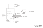
Barriers FC9Z-HA, FC9Z-HB Internal Connection IDEC IDECConnector Connector JE1S-201 JE1S-201 19 20 17 18 15 13 PLCs 11 JE1S-201 16 14 12 9 10 7 8 5 6 3 4 1 2 (Connection Side) Automation Software FC9Z-H E4 Internal Connection IDEC Connector IDEC Connector JE1S-201 JE1S-201 1 2 3 4 5 6 7 8 9 10 11 12 13 14 15 16 17 18 Power Supplies 19 20 19 20 B A 17 18 1 1 15 16 2 2 13 14 3 3 11 12 4 4 5 5 9 10 6 6 7 8 7 7 5 6 8 8 9 9 3 4 1 2 (Connection Side) (Connection Side) Fujitsu Connector FCN-367J040-AU/F (Connection Side) Connector A IDEC JE1S-201 2 1 4 3 6 5 8 7 10 10 10 9 12 11 Y-shaped Compression Terminal Y-shaped Compresion Terminal (Marking Tube No,) (Marking Tube Number) 1 3 5 7 9 11 13 15 17 19 14 13 16 15 18 17 20 19 Sensors 11 11 2 1 12 12 4 3 13 13 6 5 14 14 8 7 15 15 10 9 16 16 12 11 17 17 14 13 18 18 16 15 19 19 18 17 20 20 20 19 2 4 6 8 10 12 14 16 18 20 (Connection (Connection Side) Side) Precautions for Operation Installation of EB3L Discrete Output Barriers 4. In order to prevent contact between intrinsically safe circuits and non-intrinsically safe circuits, mount EB3L units with terminals arranged in the same direction. 1. The EB3L can be installed in any direction. 2. Install the EB3L discrete output barrier in a safe area (non-hazardous area) in accordance with intrinsic safety ratings and parameters. To avoid mechanical shocks, install the EB3L in an enclosure which suppresses shocks. Communication Connector B IDEC JE1S-201 3. When installing or wiring the EB3L, prevent electromagnetic and electrostatic inductions in the intrinsically safe circuit. Also prevent the intrinsically safe circuits from contacting with another intrinsically safe circuit and any other circuits. Intrinsically Safe Circuit Non-intrinsically Safe Circuit EB3L EB3L IDEC Connector IDEC Connector JE1S-201 BX9Z-HB Internal Connection EB3L EB3L EB3L OI Touchscreens EB3L Intrinsically Safe Circuit Maintain at least 50 mm clearance, or provide a metallic separating board between the intrinsically safe circuit and non-intrinsically safety circuit. When providing a metallic separating board, make sure that the board fits closely to the enclosure (top, bottom, and both sides). Allowable clearance between the enclosure and board is 1.5 mm at the maximum. 5. Maintain at least 6 mm (or 3 mm according to IEC60079-11: 1999) clearance between the terminal of intrinsically safe circuit and the grounded metal part of a metal enclosure, and between the relay terminal block of an intrinsically safe circuit and the grounded metal part of a metal enclosure. The clearance of 50 mm between the intrinsically safe circuit and non-intrinsically safe circuit may not be sufficient when a motor circuit or high-voltage circuit is installed nearby. In this case, provide a wider clearance between the circuits referring to 6. (3) “Minimum Parallel Distance between the Intrinsically Safe Circuit and Other Circuits.” 6. For installing the EB3L, mount on a 35-mm-wide DIN rail or directly on a panel using screws. The EB3L can be installed in any direction. Make sure to install securely to withstand vibration. When mounting on a DIN rail, push in the clamp completely. Use the BNL6 end clips on both sides of the EB3L to prevent from moving sideways. Barriers 7. Excessive extraneous noise may cause malfunction and damage to the EB3L. When extraneous noise activates the voltage limiting circuit (thyristor), remove the noise source and restore the power. 246 www.IDEC.com