1
Barriers
EB3N
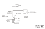
Switches in the Hazardous Area
1. Install the EB3N in an enclosure capable of protecting against mechanical
shocks at a hazardous location in accordance with intrinsic safety ratings and
parameters.
1. A switch contains the switch contact, enclosure, and internal wiring. A switch
contact refers to an ordinary switching device which consists of contacts only.
2. When the switch has internal wiring or lead wire, make sure that the values
of internal capacitance (Ci) and inductance (Li) are within the certified values.
3. Enclose the bare live part of the switch contact in an enclosure of IP20 or
higher protection.
4. Depending on the explosion-protection specifications of TIIS, the exposed
area of plastic switch operator, when installed in Japan, is limited as follows:
Certification
Explosion Protection
Exposed Area
TC15758
Exia II CT6
20 cm2 maximum
TC15961
Exia II BT6
100 cm2 maximum
PLCs
2. Install and wire the EB3N so that the EB3N is not subject to electromagnetic
and electrostatic induction and does not contact with other circuits.
For example, keep a minimum spacing of 50 mm between intrinsically safe
and non-intrinsically safe circuits, or provide a metallic separating board
between the intrinsically safe circuit and non-intrinsically safe circuit. When
providing a metallic separating board, make sure that the board fits closely to
the enclosure (top, bottom, and both sides). Allowable clearance between the
board and the enclosure is 1.5 mm at the maximum.
When a motor circuit or high-voltage circuit is installed nearby, keep a wider
spacing than 50 mm between intrinsically safe and non-intrinsically safe
circuits.
OI Touchscreens
Notes for Explosion Protection Safety
Automation Software
3. Keep a minimum spacing of 3 mm between the terminal or relay terminal
block of the intrinsically safe circuit and the grounded metal parts of the
metal enclosure.
4. Connect the terminals so that IP20 is ensured.
5. To prevent disengaged wires from contacting with other intrinsically safe
circuits, bind together the end of wires.
6. Make sure that the voltage of the power supply for the devices connected to
the non-intrinsically safe circuit or the internal voltage of such devices does
not exceed 250V AC/DC 50/60 Hz (UL rating: 125V AC 50/60 Hz) or 250V DC
(UL rating: 200V DC) under any normal and abnormal conditions.
Power Supplies
7. Make sure that the wiring of intrinsically safe circuits does not contact with
other circuits or is not subject to electromagnetic and electrostatic inductions,
otherwise explosion protection is not ensured.
8. When identifying intrinsically safe circuits by color, use light blue terminal
blocks and cables.
Sensors
9. When wiring the intrinsically safe circuit, determine the distance to satisfy
the wiring parameters shown below.
a) Wiring capacitance Cw ≤ Co – Ci
Co: Intrinsically safe circuit allowable capacitance
Ci:
Internal capacitance of switches
b) Wiring inductance Lw ≤ Lo – Li
Lo:
Intrinsically safe circuit allowable inductance
Li:
Internal inductance of switches
c) Wiring resistance ≤ Rw
Rw:
Allowable wiring resistance
Communication
Barriers
800-262-IDEC (4332) • USA & Canada
233