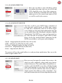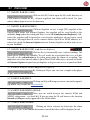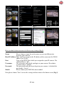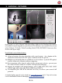
1
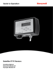
Handbuch
User Manual
IN-6014 HD
/ Integrated Passive Infrared Motion Detector
/ Wide Dynamic Range 720p CMOS Sensor for adverse lighting conditions
/ Automatic alarm by email and FTP video upload
/ Video recording on SDHC card (up to 32 GB)
/ Easy camera configuration via the integrated WebUI
/ Multi-level user managment and access control
/ Accessible over the internet via preinstalled DDNS address
/ Smartphone App InstarVision (iOS, Android, WinPhone, Blackberry, Kindle)
/ Scheduled motion detection via image analysis
/ 4mm wide-angle lens with 90º diagonal view
6014
Wide-Dynamic Range CMOS Sensor
The OmniVision® WDR Sensor raises the bar in security imaging with a
single-chip SOC sensor that combines 720p high-definition video with
WDR in a 1/3-inch optical format.
The sensor is build on a 4.3 micron OmniPixel3-HS™ pixel enabling 720p
HD at unparalleled low-light sensitivity and a dynamic range in colour
of 115dB - compared to the 60 dB of a regular VGA IP camera. Allowing
you to capture detail-rich colour video even in high-contrast lighting
conditions.
The 1280x720 pixel array provides 720p HD video at 25 frames per second broadening the scope of your surveillance.
INSTAR HD IP Camera – Usermanual
INSTAR
IN-6014 HD
1.
SAFETY WARNINGS........................................................................3-EN
2.
PRODUCT FEATURES.......................................................................4-EN
3.
INSTALLATION...................................................................................5-EN
4.
START UP.............................................................................................8-EN
5.
THE WEB USER INTERFACE.........................................................11-EN
5.1
SOFTWARE..........................................................................................12-EN
5.1.1 LANGUAGE........................................................................................12-EN
5.1.2 REBOOT/RESET.................................................................................12-EN
5.1.3 BACKUP..............................................................................................12-EN
5.1.4 UPDATE..............................................................................................12-EN
5.2
NETWORK............................................................................................13-EN
5.2.1 IP CONFIGURATION........................................................................13-EN
5.2.2 WiFi ....................................................................................................13-EN
5.2.3 DDNS..................................................................................................14-EN
5.2.4 P2P (Point-to-Point)............................................................................15-EN
5.2.5 UPnP....................................................................................................15-EN
5.3
SYSTEM.................................................................................................16-EN
5.3.1 INFO....................................................................................................16-EN
5.3.2 DATE & TIME.....................................................................................16-EN
5.3.3 USER...................................................................................................16-EN
5.3.4 STATUS LED.......................................................................................16-EN
5.3.5 IR LED.................................................................................................17-EN
5.3.6 ONVIF.................................................................................................17-EN
5.3.7 PTZ.....................................................................................................17-EN
5.3.8 SYSTEM LOG......................................................................................17-EN
5.4
MULTIMEDIA.......................................................................................17-EN
5.4.1 AUDIO.................................................................................................17-EN
5.4.2 VIDEO.................................................................................................18-EN
5.4.3 IMAGE.................................................................................................18-EN
5.5
ALARM..................................................................................................18-EN
5.5.1 AREAS.................................................................................................18-EN
5.5.2 ACTIONS.............................................................................................19-EN
5.5.3 SCHEDULE.........................................................................................20-EN
5.5.4 SMTP SERVER....................................................................................20-EN
1-EN
5.5.5 EMAIL.................................................................................................20-EN
5.5.6 FTP......................................................................................................21-EN
5.5.7 PHOTO SERIES...................................................................................21-EN
5.5.8 SD CARD.............................................................................................22-EN
5.6
RECORDING ........................................................................................22-EN
5.6.1 SCHEDULE..........................................................................................22-EN
5.6.2 VIDEO..................................................................................................22-EN
5.6.3 PHOTO SERIES.....................................................................................22-EN
5.7
MENU BAR............................................................................................23-EN
5.7.1 SD CARD.............................................................................................23-EN
5.7.2 SNAPSHOT..........................................................................................23-EN
5.7.3 RECORD (only Internet Explorer)........................................................23-EN
5.7.4 PLAYER (only Internet Explorer)..........................................................23-EN
5.7.5 HELP....................................................................................................23-EN
5.7.6 MJPEG (h.264).....................................................................................23-EN
5.7.7 ALARM................................................................................................23-EN
5.8 VIDEO MENU BAR................................................................................24-EN
5.8.1 AUDIO (only Internet Explorer)...........................................................24-EN
5.8.2 MICROPHONE (only Internet Explorer).............................................24-EN
5.8.3 DIGITAL ZOOM (only Internet Explorer)...........................................24-EN
5.8.4 RECORD PATH (only Internet Explorer).............................................24-EN
5.9 PAN&TILT CONTROL............................................................................24-EN
5.9.1 CONTROL PAD..................................................................................24-EN
5.9.2 POSITIONS.........................................................................................25-EN
5.10
WEB USERINTERFACE UPDATE.......................................................25-EN
6. RESET YOUR CAMERA..........................................................................25-EN
7. LENSE ADJUSTMENT.............................................................................26-EN
8. ANDROID AND iPHONE APP.............................................................26-EN
9. WINDOWS SOFTWARE.........................................................................28-EN
10. RTSP STREAMING.................................................................................30-EN
11. TECHNICAL DATA..................................................................................31-EN
12. WARRANTY & DISPOSAL....................................................................32-EN
13. FAQ Questions & Answers......................................................................33-EN
14. AVAILABLE ACCESSORIES..................................................................35-EN
More user manuals can also be found
on download.instar.de
Your Manufacturer for Network and
Security Technology
2-EN
1 l SAFETY WARNINGS
Please read the following safety warnings carefully and keep them in a safe place.
» Make sure the power cord is not near any hot surfaces.
» Place the Power and Network cable properly so that no one can be hurt.
» This device shall not be used by people (including children) with limited
physical, sensory and mental capabilities. Only the trained person that knows
how to use the device carefully can use the device.
» Children should be supervised to make sure they don’t play with the device.
» If the power cord of this device gets damaged, it can only be replaced by the
manufacturer or the customer service person or a similar qualified person to
avoid any damage to you and the device.
» Never do any repair by yourself. By opening the device the warranty will automatically expire. If any repair is needed, please contact your INSTAR Service Center.
» When cleaning, please never place the device in water.
» Make sure you only install the device in a 100V - 240V power socket.
» This device is only suitable for indoor use.
» Only use this device to secure your home, office and similar places. If you are planning to install the device in an public area please make sure you have all certificates
to do so.
» Never install the device near explosive or flammable substances.
» Don’t use the camera for any other purpose that it isn’t made for.
» INSTAR does not give any warranty if you use any third party firmware or WebUI.
» Please note that this is an indoor camera which is made for indoor surveillance only.
CE-Conformity
This device suites the basic requirements of the European regulations for electromagnetic
compliance (2004/108/EC) and the low voltage regulations (2006/95/EC ).
3-EN
2 l PRODUCT FEATURES
Hardware
» Integrated passive Infrared Motion Detector
» Wide Dynamic Range Megapixel CMOS sensor and ARM media processor
» 12 Infrared-LEDs for nightvision 8 - 12 m
» Resolution: 720p (1280 x 720), 640 x 352 and 320 x 176
» Exchangeable wide angle lense with a 90º diagonal field of view
» Automatic IRcut filter for realistic colours during the day
» Integrated SDHC card slot for microSD cards up to 32 GB
» Pan&Tilt: 350 º horizontal and 100 º vertical
Connectivity
» 10/100Mbit ethernet interface to connect to your router or PC
» WLAN compatible - 2.4 GHz Wi-Fi 802.11b/g/n
» Remote access your live video with your smartphone (iOS, WinPhone8 & Android)
Software
» h.264 video encoding for reduced bandwidth requirements
» Video and snapshot recording on SD card is supported
» Video recording by alarm and FTP upload (only with SD card)
» Software based motion detection by image analysis / Alarm notification by email
» Email and FTP snapshot upload - continuous and alarm triggered
4-EN
3 l INSTALLATION
1
2
3
4
7
8
9
10
11
12
5
6
13
Fig. 1 Front
14
Fig. 2 Rear
15
Fig. 3 Bottom
1
Photosensor
Twilight-Switch for IR LEDs
2
Lense
Wideangle-lense (focal length: 4.3mm / field of view: 90.º hor.)
3
Infrared-LEDs
12 IR LEDs (nightvision @ 850nm)
4
PIR Detector
Integrated passive Infrared Motion Detector
5
Loudspeaker
Integrated Loudspeaker (s. 5.7.2)
6
Microphone
Audio transmission (s. 5.7.2)
7
Power Connector
5V / 1.5 A DC - Plug Ø : 1.35mm (in) / 3.5mm (out)
8
LED Indicator
Red: power LED; blue: Status-LED for network traffic
9
Reset Button
(also WPS Button)
Reset camera to the factory default setting by pressing 15 seconds.
(WPS function: press 3 seconds to connect with Wifi Router)
10 MicroSD Card Slot
Slot for SD/SDHC cards up to 32 GB (4 GB included)
11 Antenna Connector
SMA WiFi antenna connector
12 Network Port
RJ45 LAN-port for the provided CAT5e LAN cable
13 Audio Out
3.5mm earphone / active speaker jack
14 Camera ID
MAC address LAN and QR for the P2P connection
15 Stand Mount
Standard camera thread for provided stand support
5-EN
Connect the camera to your Network
Take out the package content from the box: the camera, a CAT5e LAN cable, a 2.4 dBi
SMA WiFi antenna, mounting bracket and the software CD.
Connect the WiFi antenna to the antenna connector at the
back of camera, align it vertically to your router and place the
camera close to your Wifi router for the rest of the installation
process. Please be aware that the camera has to be installed via
LAN cable first before it can be used in your wireless network
- for an alternative network connection, please refer to the included flyer Plug&Play for a WPS integration.
Plug one end of ethernet cable to the RJ45 LAN
port on the camera housing and the other end to a
free LAN port of your network router. For a direct
connection to your Windows PC or Mac, please refer to our online FAQ section on faq.instar.de. But
we recommend to connect the camera to your network router for the initial installation.
Connect the power adapter to the camera cable and plug it into
a suitable power outlet. Both network indicator LEDs on the network port will light up showing that the camera is connected to
your network.The camera will now execute a pan&tilt calibration.
The orange LED of the LAN port signals a hardware link
to your router and therefore should be on continuously.
The green LED should be flashing irregularly indicating
network traffic. The green status LED on the power supply
has to be on continuously indicating a steady power supply. Please plug the power supply directly into a wall socket.
Using it on a multi-power strip or an extension cord is not
recommended.
6-EN
Troubleshooting
The status LED of the LAN port isn’t on
Your camera doesn’t have a connection to your router because the LAN cable is damaged, the connector is loose or your camera is connected to a wrong port on your router
or switch.
The status LED of the LAN port goes on and off every x seconds
Your camera is continously restarting - possibly because of a loose contact. Please check
the power connector on the camera side. Turn the plug by 180 degrees in both direction
and check if the problem persists. Make sure the green status LED on the power supply
is on continuously.
For a direct cable connection between camera and computer, please note:
The network cable provided with the camera is not a crossover cable. It is just a normal
patch cable. Most modern computers network interfaces support the automatic switching between crossover and normal patch cable - you can use the cable that came with the
camera to connect it directly. If you are using an older system to connect your camera
directly you might need a crossover network cable.
To set up the camera for the first installation, we recommend to connect the camera
directly to your router. This router on the other side has to be connected with your computer. Other ways of connections are only recommended for experienced users. Please
refer to our online documentation on http://faq.instar.de.
Connect the camera using an IN-LAN® Adapter (optional)
Simply plug one IN-LAN adapter into a power socket next to your broadband router
and connect the adapter to your router via an Ethernet cable. Plug the second IN-LAN
unit into an outlet close to your INSTAR camera and connect the camera to the IN-LAN
adapter using the camera’s Ethernet cable.
IN-LAN 500/p
Powerline Adapter
IN-LAN uses the household power grid to transfer data between
computers equipped with suitable
adapters and other network components. As a result, any power outlet can be used as a
network access point. IN-LAN is an intelligent and secure technology that lets you set
up a home network easily via your household power grid - without the need of complex
and expensive dedicated cabling.
Additional accessories, like the IN-LAN Adapter, can be found in the accessories of your camera model on www.instar.de.
7-EN
4 l START UP
To install your camera please open the installation CD or simply
go to http://install.instar.de. Please follow each step for an easy
first setup of your camera. To find the camera in your network
we provide you with a free Windows, MacOS and
Linux tool that allows you to find, update and open
your camera on your computer. As an alternative you
can also use an IP scanner or check inside your router to find out the ip address of your new ip camera.
4.1 l NETWORK INSTALLATION
Please start the setup wizard from the CD and install the INSTAR Camera Tool
linked on the CD for Windows, LINUX or MacOS. (You can find documentations
for the use of other IP scanners on http://faq.instar.de)
Please start the INSTAR Camera Tool.
The camera tool will automatically find all INSTAR IP cameras in your network
and will show their IP address.
In case your camera isn’t found right away please wait 10 to 15 seconds for your
routers DHCP service to assign an IP address to your camera.
Double-click the camera’s IP address inside the camera tool to open the web user
interface (webUI) with your default browser and you will be greeted by the camera’s login window. If so, please skip the following paragraph and go straight to 4.2
LOGIN (see page 11).
8-EN
Troubleshooting:
In case the INSTAR Camera Tool doesn’t find your INSTAR IP camera please make sure
that the status LED for the LAN connector is active. For troubleshooting please check
on page 8 in this user manual.
In case your camera isn’t automatically assigned an IP address, the camera will be shown
inside a wrong IP address space. A double click on the camera’s IP will then open the
IP / Network configuration window (see below) allowing to manually assign an address.
Please set the following information according to your network:
- IP Address (for example 192.168.x.x)
- Subnet Mask (for example 255.255.255.0)
- Gateway (IP Address of your router; for example 192.168.x.1)
- DNS Server (IP Address of your router; for example 192.168.x.1)
- Http Port (TCP Port; for example 80)
To check the IP address of your Windows computer and your network parameters
please do the following:
1.
2.
3.
Click on [START] -> and type in “cmd” into the search field.
In the window that pops up please type “ipconfig”.
Now the IP address and the subnet mask will be shown.
9-EN
EXAMPLE:
If your gateway is “192.168.178.1”, please fill in the camera information accordingly:
- IP Address of the Camera: 192.168.178.190. (“190” is just an example)
- Subnet Mask: 255.255.255.0
- Gateway: 192.168.178.1
- DNS Server: 192.168.178.1
- Http Port: 80 (default port, can be changed)
How to setup your camera without a router:
If you want to connect your camera directly to your computer, please set a fixed IP
address for the network interface in your computer, as well as for the IP camera. You
can set the camera IP by using the INSTAR Camera Tool. As for Gateway and DNS
server please fill in the computer IP. After submitting the settings to the camera please
wait a moment until the camera has restarted. For a detailed instruction please refer to
our FAQ section on http://faq.instar.de
4.2 l LOGIN
For the first installation of the camera please log in
with the following username and password:
user:
password:
admin
instar
4.3 l PLUGIN INSTALLATION (only Internet Explorer)
4.3.1 After the login (Internet Explorer) you will be asked to install the ActiveX control element. Please run it and confirm when your Internet Explorer is asking you to
install the control element:
10-EN
After the installation, please restart your Internet Explorer, a window will pop up as
below. Please press “Allow” to run the ActiveX control element in your web browser:
4.3.2 Accessing with other browsers (Firefox, Chrome, Safari,...)
In order to access the live video stream through other web browsers, please install the
Quicktime Player. Please follow the enclosed A5 Quick Installation manual.
Also check the FAQ section at the end of this user manual (chapter 13) or visit the FAQ
section on http://wiki.instar.de for more detailed instructions.
5 l THE WEB USER INTERFACE
11-EN
5.1 l SOFTWARE
5.1.1 SOFTWARE/LANGUAGE
Here you can choose the language of the web user interface. The web user interface will reload after you click
submit.
5.1.2 SOFTWARE/REBOOT-RESET
Here you can check the user interface and firmware versions. To restart or reset your camera simply check the
corresponding box and click submit. To avoid an unwanted reset, a remark will be show in a new window and
you need to confirm the command a second time after a
10 seconds countdown.
5.1.3 SOFTWARE/BACKUP
To save your camera settings please check the corresponding box and click submit and you will be asked for
a file path and name. The default is config_backup.bin and
the file path is the download folder of your browser. To
restore the settings check “Load Backup Copy”, browse
for the backup file and click submit.
5.1.4 SOFTWARE/UPDATE
You can download regular software updates for your camera from http://download.instar.de. Please use the browse
button to set the file path to the downloaded *.PKG file
and click “Submit” to upload the file to your camera. Use
the update function only when the camera is connected to
the router by LAN cable!
12-EN
5.2 l NETWORK
5.2.1 NETWORK/IP CONFIGURATION
You can set whether the camera will be assigned an IP
address by your router (DHCP) or you want to manually
set a fixed address. Please check page 9 &10 on how to
set a fixed IP address. In general, we recommend that you
deactivate the automatic service and set a manual IP to
avoid further trouble with the remote access to your camera. For the RTSP Port please refer to 10. RTSP Streaming
for details on the use of the camera´s RTSP videostream.
5.2.2 NETWORK/WiFi (not applicable for PoE Model)
If you cannot use the WPS service (Wireless Portected Setup) to integrate the camera into you local WiFi network see included flyer Plug & Play for further information for the
WPS function - click search
to start the WLAN scanner.
Just choose your own network and click “Join”. Now you
simply have to add the WiFi password (WLAN Key) and
click submit to save the settings. Afterwards you can use
the Test function to verify your settings. Please disconnect the LAN cable and wait about
30-60 seconds for the camera to connect to your WiFi network. The camera will receive
a new address from your router if you didn’t assign a static IP address to your camera
previously (Chapter. 5.2.1), therefore you should use the INSTAR Camera Tool again to
rediscover your camera (Chapter 4).
Attention:
Your WiFi modules MAC address is not identical with the LAN MAC address of your
camera! If you are using a MAC filtering rule for your WiFi network, please deactivate
the filter and add your camera to the list of trusted devices before reactivating it.
Additional Remark:
Your camera supports a range of encryption standards - we recommend for the safety
and reliability of your connection - that you set your WiFi network to WPA2 (PSK) with
AES (or CCMP). With older routers choose WPA (PSK) / AES. Avoid using a mixed
mode like WPA&WPA2 - TKIP! If your WiFi stays unstable please choose a fixed WiFi
channel for your router - we recommend the channels 1 - 6.
13-EN
5.2.3 NETWORK/DDNS
Your camera comes with a personal DDNS address e.g. http://xxxx77.ddns-instar.de. Everything you need
for a remote access to your camera is a port forwarding rule in your router. You can access your camera afterwards through the internet using this http address.
Please refer to FAQ Chapter #13. 4) for port forwarding or visit our online FAQ section
on http://faq.instar.de for detailed information on the port forwarding setup as well as
video instruction for many common routers. Or refer to your router’s user manual for
further guidelines on how to set up a port forwarding rule.
EXAMPLE Portforwarding - Netgear:
Please refer to our online help http://faq.instar.de for detailed instructions for all commen routers.
In case you want to use an account from DynDNS.org simply choose the third party
service and type in your personal login credentials. By doing so you will temporarily
deactivate your INSTAR DDNS address.
If you are using several cameras behind a single internet access point, please set up the
third party address in only one of the cameras. Or if possible directly inside your router!
All your cameras will be accessible through this address - just assign a unique HTTP
port to every camera (s. 5.2.1). For example if camera 1 is assigned the HTTP port 85
and camera 2 the HTTP port 86, use myaddress.dyndns.org:85 to reach camera 1 and
myaddresse.dyndns.org:86 to be forwarded to camera 2.(more details please see FAQ)
14-EN
5.2.4 NETWORK/P2P (Point-to-Point)
Activate the P2P function to access your camera from
the internet without the need for a port forwarding
in your router (s. 5.2.3). Simply add the camera as a
P2P camera in our InstarVision app (s. 8), scan the
QR code on the Network/P2P overlay in the webUI
or from the label on the camera and add the cameras
administrator login (s. 4.2).
You can access your camera even behind an IPv6 connection or mobile Router
(UMTS/LTE, with changing WAN IP)! Use the P2P function to access your camera from
the internet, when you cannot set a port forwarding for the camera that is necessary for
the DDNS service (s. 5.2.3).
1
2
Manually type in your User ID or...
3
...use the automatic network or QR scanner.
QR Code
There are 3 ways to connect your camera with the INSTAR App
1 Tap the “Search” button to find the p2p camera inside your local network
2 Type in the “UID” from the camera´s web UI or from the label on the camera case.
3 Click QR Scan and use your smartphone to scan the QR code on the webUI or
on the label that you can find on the camera casing.
Please note that the QR code in the webUI and on the product label both contain the
UID, camera model, admin username and password for a quick setup. Please note that
the username and password on the product label are only default settings (s.4.2), while
the webUI QR code will be always up-to-date with the log-in credentials. We recommend that you change the administrator password of the camera (s. 5.3.3) and use the
QR code from the webUI. Please restart the camera after changing the password.
ATTENTION: The P2P connection ONLY works with the admin user!
5.2.5 NETWORK/UPnP
If you are using Universal Plug and Play(UPnP) for
your network devices, please activate the UPnP service in your camera. In case you are using a manual port forwarding rule in your router to access your
camera from the internet, make sure the cameras
UPnP service is deactivated! We recommend setting
up a manual port forwarding.
15-EN
5.3 l SYSTEM
5.3.1 SYSTEM/INFO
The Info menu gives you an overview of several important camera parameters - like your software version and connection status.
5.3.2 SYSTEM/DATE & TIME
You can set up the internal clock of the camera to be
either synchronised with your PC clock or with one of
several NTP servers. As long as your camera has access to the internet it is recommended to use an NTP
server synchronisation to achieve a higher accuracy
for alarm trigger events. Please activate “Consider
Daylight Saving Time” when in effect.
5.3.3 SYSTEM/USER
The web user interface offers a 3-level user management with different access rights for administrators,
operators and visitors. You can set user names and
passwords for all three user levels in the Users mask.
Guests will only have access to the videostream of the
camera, Userss in addition are able to use the pan&tilt
function and only the Administrator will have access to
all the camera’s configuration menus.
5.3.4 SYSTEM/Status LED
Here you can adjust the behaviour of the network status LED. You can turn off the blue status LED (which
can be found at the back of the camera) or you can
turn it on in order to signal if there is a network connection or not.
16-EN
5.3.5 SYSTEM/IR LED
Here you can activate or deactivate the infrared LED
on the camera. Please note if you deactivate the infrared LED, the nightvision of the camera will be gone.
5.3.6 SYSTEM/ONVIF
ONVIF is a global standard for the interface of IPbased security products. The ONVIF specification will
ensure interoperability between products regardless of
manufacturer, allowing you to integrate your INSTAR
camera as a generic ONVIF camera into existing security systems.
5.3.7 SYSTEM/PTZ
ONVIF is a global standard for the interface of IPbased security products. The ONVIF specification will
ensure interoperability between products regardless of
manufacturer, allowing you to integrate your INSTAR
camera as a generic ONVIF camera into existing security systems.
5.3.8 SYSTEM/SYSTEM LOG
The System log shows general notifications for
the state of the cameras operating system .
5.4 l MULTIMEDIA
5.4.1 MULTIMEDIA/AUDIO
Here you can adjust the volume of the cameras integrated microphone and speaker.
17-EN
5.4.2 MULTIMEDIA/VIDEO
The video settings allow you to adjust the quality of all
3 videostreams of your camera. Please be adviced that
high quality settings come with high requirements for
your computer hardware and network bandwidth. Adjust the video quality to obtain a fluent video accordingly. Please refer to chapter 10: RTSP Streaming for
accessing the cameras streams 2 and 3.
The MJPEG mode of the camera allows you to access the videostream with your browser
without the need of additional browser-plugins! You can use the MJPEG mode when
you are accessing the camera from a system that doesn’t allow you to install the ActiveX
control element or the QuickTime plugin for Firefox, Chrome or Safari. Please consider
that this mode is only for viewing the live image of your camera. Even with only one user
logged in your cameras framerate might drop below 4 fps because of the high bandwidth
requirements!
5.4.3 MULTIMEDIA/IMAGE
Here you can adjust the image parameters brightness,
saturation, contrast, exposure (shutter) and sharpness.
You can flip and mirror the video image, can display a
timestamp and set a camera name and display it as well.
The displayed parameters are burnt into the camera image. Please make sure to restart the camera after changing the name.
5.5 l ALARM
5.5.1 ALARM/AREAS
Your camera detects motion by a picture analysis that is sensitive to every change inside
the video frame instead of employing an infrared or microwave sensor. In “Areas” you
can adjust up to 4 detection areas in size and sensitivity for trigger event. Once the motion detection in an area is activated, its sensitivity can be adjusted from very insensitive
(value=0) to very sensitive (value=100).
18-EN
In case the camera’s position is prone to rapid light changes, e.g. changes in sun intensity
due to cloud movements, you might be confronted with a high number of false alarms.
In this case please refer to 5.5.2 for employing external PIR motion detection sensors.
5.5.2 ALARM/ACTIONS
Adjust the cameras behaviour in case of a motion alert
trigger event. You can set the camera to send you an
email and to save snapshots or videos on your SD
card. Please make sure you set your SMTP server settings before activating the email notification (s. 5.5.4
& 5.5.5) and that you have a SD card in your cameras
SDHC card slot (max. 32 GB) to use the video recording and send-to-FTP function (s. 5.5.6) - a 48 GB SD card is included in the delivery.
For
For video
video as
as well
well as
as picture
picture recordings
recordings the
the camera
camera will
will create
create aa folder
folder on
on your
your SD
SD card
card
with the
the date
date of
of the
the current
current day.
day. If
If the
the SD
SD card
card is
is full,
full, the
the oldest
oldest day/folder
day/folder will
will automatiautomatiwith
cally
all recordings
recordings in
in this
this folder.
folder. The
The bigger
bigger your
your MicroSD
MicroSD card
card is,
is,
cally be
be deleted
deleted and
and with
withitit all
which
you
install
in
the
camera,
the
more
days
(recordings)
you
can
save
on
the
SD
card.
which you install in the camera, the more days (recordings) you can save on the SD card.
The camera
camera automatically
automatically records
records videos
videos with
with aa length
length of
of 15
15 seconds.
seconds. Since
Since the
the camera
camera
The
also
also supports
supports prerecording,
prerecording, 2-3
2-3 seconds
seconds will
will be
be added
added to
to the
the recording.
recording. This
This way
way you
you will
will
be
be able
able to
to see
see 2-3
2-3 “before”
“before” the
the actual
actual alarm
alarm event
event is
is happening.
happening.
You can use a motion detector like the IN-Motion 500
You could reduce the video resolution in order to be able to store more recordings on the
(outdoor)
to improve
theavailable.
detection
your camstorage card. Therefore we
offer 3 video
resolutions
Therate
HD of
resolution
with
era.asSimply
thewith
sensor
to the
alarm
input
and
1280x720 resolution as well
the VGAconnect
resolutions
640x352
and
320x175
pixel.
activate the external input. An alarm will be triggered
The IN-6014 HD gives you
advanced
PIR detection
technology
integrated
PIR
once
the circuit
(pins 3&4
- see pagewith
5) isanbroken
by the
sensor at the camera front.
This
sensor
rotates
along
with
the
camera
to
detetct
motion
relay inside the detector (n.c. “Normally Closed”) or if
infront of the camera. By
“external input” The
in Actions
underhave
Alarm
theactivating
wire is disconnected.
state you
to category
choose
in the webUI, the camera combines the motion detection software function and the PIR
depends on your sensor - the wrong choice will give a
sensor for monitoring motion and trigger alarm events. in other words, only when both
alert detects
once the
detector
connected.
Please
motion detection featurecontinous
and PIR sensor
a motion,
willisthe
camera trigger
an
to the Motion
Detector
userrains,
manual.
alarm event and send therefer
notification
to the user.
Therefore,
moving treeleaves,
small bugs appearing in front of the camera which usually cause false alarms will be
The
external
connectsoftothe
a relay
insidePIR
thesensor.
camera
bethat
switched
avoided
due tooutput
the application
integrated
Butthat
be can
aware
it also
might eliminate
a few positive alerts
- use
with caution.
manually
or automatically
in case
ofthis
an function
alarm event.
Please check Activate
External Output to let the camera open or close a circuit with an external
device connected to the pins 1&2 (s. page 5). The external output can be used
with the cameras motion detection to activate signaling devices like sirens or
LED lights. It can also be used to control connected devices manually, e.g. via
our smartphone app. The relay can be connected to circuits with up to 60 V
direct current / 125 V alternating current and max. 1 A.
19-EN
5.5.3 ALARM/SCHEDULE
Here you can define a time schedule in which
the motion detection, that was set in 5.5.1 and
5.5.2, should be active. Every blue square represents 30 minutes of motion detection. Please
make sure to set the correct time zone in 5.3.2
as it will be used by the camera.
5.5.4 ALARM/SMTP SERVER
You have to fill in your SMTP login credentials of
your personal email account to enable your camera
to send you a notification email in an alarm trigger
event. Simply use the same login information that you
use for email clients like Microsoft Outlook or Mozilla
Thunderbird. The SMTP user name and password are
the same that you use to login to your email account.
Please check your email provider’s homepage for the
SMTP server address, server port and encryption:
Gmail - smtp.googlemail.com (SSL; Port 465 or 587)
GMX - mail.gmx.net (SSL; Port 25, 587 or 465)
T-Online - smtpmail.t-online.de (Port 587 or 25)
bluewin.ch - smtpauth.bluewin.ch (Port 587)
Strato - smtp.strato.de (Port 25)
The camera will use this email address to send you alarm notification. You can set the
email recipient under 5.5.5.
5.5.5 ALARM/EMAIL
Here you need to input the sender, the receivers, the
subject as well as optional a short email text of maximum 64 characters. The sender address should be in accordance with the SMTP server data (s.5.5.4), though
some email provider let you choose this field freely. If
you want to send the email to more than one address,
simply separate the addresses with a semicolon ‘;’. E.g.
[email protected];[email protected]
20-EN
5.5.6 ALARM/FTP
After activating the FTP upload function (s.5.5.2 Actions), you have to set your ftp server address and
login credentials. You can for example use your routers
FTP service as FTP Server - in this case simply put in
your router’s IP as the FTP Server address. If you set up
a FTP server on a local PC (for example with Filezilla
Server), use the PC’s local IP address. Of course you
can use a webservers URL’s as well. The standard FTP
port is 21.
You can define an upload directory for your camera under FTP Folder. The root folder
of the FTP server can be reached by “./”. The separator for the folders is the forward slash.
A subfolder (e.g. INSTAR) can be reached by “./INSTAR”. An ending forward slash is not
obligatory, but can be used.
The FTP Username and FTP Password are the login credentials for your FTP account.
For the FTP Mode you can choose between a passive (PASV) and an active mode
(PORT). The default is the active PORT mode. If your server is installed behind a router
with an active network address translation (NAT), or if a firewall is blocking the server’s
network from an external access by your camera, you should choose the PASV mode.
The name of the video file is fixed and corresponds to the following syntax: rec011_
YYYYMMDDhhmmss.asf. The first part show the channel 11 for recording. Separated
by an underscore it shows the timestamp, which marks the time of the motion detection.
Please refer to our website for information on how to set up a FTP server.
5.5.7 ALARM/AUDIO ALARM
The camera can also detect loud noises and cause an
alarm. Therefore, simply enable the audio alarm and
set the sensitivity for the volume that needs to be
reached in order to trigger an alarm.
1 = not sensitive
10 = very sensitive
21-EN
5.5.8 ALARM/SD CARD
Please check the corresponding box and click submit to
either format or unmount your SD card.
A click on the link above the submit button will lead
you to the SD card directory where all your snapshots
and videos will be stored. Use your camera admin
login to access the directory.
5.6 l RECORDING
5.6.1 RECORDING/SCHEDULE
Here you can set the schedule for the photo series as
well as for the continual video recording to SD card.
Every blue box represents 30min of activity. The recorded files will be stored to the camera’s internal SD
card. The file name will start with a capital “P” to differentiate them from alarm recordings “A” and test images that start with a “T”.
5.6.2 RECORDING/VIDEO
In this menu you can activate the continuous video recording to SD card. Here, you can set the video
lengths and video resolution. The max. time per file is
15 minutes.
For this function we recommend you to use a larger
size MicroSD card (max. 32GB) in order to prevent the
card from being overwritten too soon.
5.6.3 RECORDING/PHOTO SERIES
Here you can activate the recording of a snapshot series
in a selectable span of time. The snapshots will be saved
to a SD card which has to be in the camera’s SDHC slot
(a 1 GB SD card is included in the delivery). The JPG
snapshot can later be accessed via the web user interface (s. 5.7.1). For FTP upload, if you do not set a fixed
name, then the file name will be set according to this
format: PYYMMDDhhmmss00.jpg.
22-EN
5.7 l MENU BAR
5.7.1 MENU BAR/SD CARD
Click on the SD Card to open the SD card’s directory in
a new browser window or tab - all your snapshots and videos will be listed. Use your
camera admin login to access the directory.
5.7.2 MENU BAR/SNAPSHOT
Click on Snapshot to save a single JPG snapshot of the
current video frame. For Internet Explorer, the snapshot will be saved locally in the
subfolder Snap under the record path that is set in 5.8.4 (only Internet Explorer). Otherwise the snapshot will be opened in a new browser window or tab and can be saved
from there. You might have to set the cameras address (local IP or DDNS address) as a
trusted site inside the Internet Options of your Internet Explorer to allow write access
to your harddisk!
5.7.3 MENU BAR/RECORD (only Internet Explorer)
Click on Record to manually start a video recording. The
video will be saved in the subfolder “Record” under the record path that is set in 5.8.4.
You will see the red indicator in the video menu when the camera is recording. You
might have to set the camera’s address (local IP or DDNS address) as a trusted site inside
the Internet Options of your Internet Explorer to be give write access to your hard disk!
5.7.4 MENU BAR/PLAYER (only Internet Explorer)
By clicking on Player you can start a simple video player
to play your recorded video files.
5.7.5 MENU BAR/HELP
Clicking on Help will bring you to our constantly expanding online FAQ section on www.instar.de.
5.7.6 MENU BAR/MJPEG (H.264)
Here you can switch between the camera’s H.264 and
MJPEG videostream - see also 5.4.2. If you are using the IE web browser, the function
Record and Player is only supported in the H.264 mode.
5.7.7 MENU BAR/ALARM
Clicking on Alarm activates or deactivates the alarm
settings (s. 5.5.1). If the motion detection is armed the letters will be displayed in red.
23-EN
5.8 l VIDEO MENU BAR
5.8.1 VIDEO MENU BAR/AUDIO (only Internet Explorer)
Click here to activate the camera’s integrated microphone or speaker. You
can adjust the volume of the audio signal under 5.4.1.
5.8.2 VIDEO MENU BAR/MICROPHONE (only Internet Explorer)
In case your PC is equipped with a microphone, click here to activate the
audio-out of your camera.
5.8.3 VIDEO MENU BAR/DIGITAL ZOOM (only Internet Explorer)
Click here to adjust the cameras 3 x digital zoom.
5.8.4 VIDEO MENU BAR/RECORD PATH (only Internet Explorer)
Here you can set the record path for your videos and snapshots. The set path is used by all your INSTAR Megapixel
Cameras! Your camera will automatically create subdirectories with the current date and its IP address when you start
recording or take a snapshot. All snapshots will be saved in
the subdirectory “Snap” and all videos in the subdirectory
“Record”.
Note that you have to add the cameras IP or DDNS address to
the trusted sites in your web browser.
5.9 l PAN / TILT CONTROL
5.9.1 PAN&TILT CONTROL/CONTROL PAD
You can use the control pad to pan and tilt your camera´s head.
You can also start a horizontal (hscan) or vertical (vscan) patrol or
stop the cameras movement (stop). The camera will move in both
patrols into the according terminal positions and then go back
to the initial position. If you are using the Internet Explorer you
can also click into the boundary areas of the video frame to move
the camera into the respective direction and double-clicking the
center of the frame will get you into a full screen mode.
24-EN
5.9.2 PAN&TILT CONTROL/POSITIONS
You can save up to 8 camera orientations by moving the camera
into the desired direction and clicking on one of the numbered
slots after choosing Save Position. Clicking on the slots 1-8 when
Go to Position is activated will move the camera back to the saved
position. You can delete all positions by clicking on Reset all Positions. Position 1 defines the startup position of your camera!
5.9 l WEB USER INTERFACE UPDATE
How to upgrade to a new WebUI or Firmware
Please download the newest version of the WebUI or Firmware from our website. Please
follow the link below to our homepage´s download section:
http://download.instar.de
Simply select your camera model, scroll to the bottom part of the website and choose the
newest Software/Firmware for your IP camera.
The firmware file can be uploaded to your camera via the web user interface (s.5.1.4) or
by using the INSTAR camera tool.
6 l RESET YOUR CAMERA
In order to reset your camera (if you have lost your password), please hold the small
camera reset button for min. 15 seconds. Make sure the camera is connected to the
power supply. If a reset was incomplete the camera might become inresponsive. Please
repeat the reset for min. 15 s and unplug the camera over night from the power supply
before trying to restart it again.
25-EN
7 l LENSE ADJUSTMENT
The IN-6014 HD’s lense offers a limited field depth that was adjusted to a field between
1m to 10m. In case the object you want to observe lies outside of this area, you will have
to adjust the lense accordingly.
Fig. 1
Fig. 2
Fig. 3
Fig. 4
Fig. 2
Fig. 1
Fig. 1/2 Connect the camera to the powersupply and the network cable. Open the
web interface and turn the lense until you can see a clear and sharp picture.
8 l Android, WinPhone and iOS App
To integrate your IP camera in the App “InstarVision” we recommend to first download
the newest version in the App Store. To find the newest version just type “instar” for the
search.
(Fig. 1) After installing the newest version please start the app to open the following
interface (s. next page).
(Fig. 2) Now press the “New camera” button and type in all necessary data for your IP
camera.
(Fig. 3) Adjust your camera’s parameters over the apps user interface.
(Fig. 4) Press a channel to access the corresponding livestream and take control over
your camera.
26-EN
Fig. 1
Fig. 2
Fig. 3
Fig. 4
Here you find a short overview of all necessary settings (Fig.2):
Name:
Please choose a name for each camera so you can differenciate
between your cameras.
Host/IP Address: Here you have to type in the IP address of the camera or the DDNS
address (see 5.2.3).
Port:
Type in the HTTP Port which you assigned to your IP camera. The
standard Port is “80”.
Username:
The username with which you log in to your camera. The admin
account name is “admin”.
Password:
The password with which you log in to your camera. As default the
password is “instar”.
Model:
Please choose your INSTAR camera model.
Now please choose “Save” to save the settings and to return to the home screen (Fig.1).
27-EN
9 l WINDOWS SOFTWARE
sold separately
InstarVision® is a 16/32 Channel Video Surveillance Software for Windows (the number
of available channels depends on your license!) The Software can record the live stream
of any Webcam, TV Cards, Video-Recording Cards (DVR), INSTAR IP Camera or other
devices with up to 30 fps.
InstarVision® covers below features:
1). Advanced motion detection algorithm with a mask matrix – free adaption of the
motion detection mask with a 64 square resolution inside the picture.
2). Multiple ways of notification are available in case of an alarm - by email, FTP upload,
acoustic alarm or by 3rd party software triggering.
3). Easy integration of the camera’s audio & video stream into websites - present your
live video to friends, family or customers through your homepage.
4). Support for multiple video output formats: such as MP4, MOV, FLV, SWF, WMV
and AVI and video codecs like H.264, MPEG4 and WMV3.
5). An affordable price and all the functions necessary to achieve your camera’s full
potential.
A detailed online manual can be found on www.wiki.instar.de and a 7-day trial version
can be downloaded from our homepage http://download.instar.de.
28-EN
Add your INSTAR Camera to the InstarVision® Surveillance Center:
To integrate a camera in InstarVision it doesn’t take much. We recommend that you give
your camera a static IP address to prevent it from changing automatically by the DHCP
server. (s. 5.2.1).
Afterwards please open the channel setup window and choose Search
IP Camera to start the Camera Tool. Click on search to discover all
INSTAR cameras inside your local network and right-click the cameras
to assign it to a channel. The number of available channels can be set in the channel
setup window.
29-EN
10 l RTSP STREAMING
(e.g. VLC Player, iSpy..)
To use third party software you usually need the direct path for the live video in order
to grab the video from your camera. Then the program is able to grab the video stream
from your camera to work with it. You can find step-by-step instructions for several
software on our help pages on www.instar.de .
Access over your local network:
Please use the following path to use your camera with third party software:
RTSP Stream 1:
RTSP Stream 2:
RTSP Stream 3:
JPG Path:
rtsp://<user>:<password>@192.168.x.x:<RTSP Port>/11
rtsp://<user>:<password>@192.168.x.x:<RTSP Port>/12
rtsp://<user>:<password>@192.168.x.x:<RTSP Port>/13
http://<Benutzer>:<Passwort>@192.168.x.x/tmpfs/snap.jpg
Please use your camera login for the user and password values:
E.g.: rtsp://admin:[email protected]:554/11
Just substitute the “x“ according to the IP address of your camera (in case of a Netgear
router the first x = 1 and and the second x = the end octet of your camera’s IP). If you
changed your RTSP port (standard = 554) please change the value after the IP address
accordingly.
Attention: To access the cameras RTSP stream through the internet you will have to
forward the RTSP port (standard = 554) to your camera’s IP address. See chapter 5.2.3
and the forwarding procedure for the LAN (HTTP) port (standard 80) for reference.
Access via internet:
Please use your DDNS address to remote access your camera’s RTSP stream:
rtsp://<user>:<password>@xxx.ddns-instar.de:<RTSP Port>/11
xxx = please check your personal DDNS address under network/DDNS (s. 5.2.3)
Tip: Your camera offers you 3 RTSP streams with different bitrates. Please choose
stream 2 or 3 if your available bandwidth is limited or you are using a computer with
limited processing power (e.g. netbook). You might encounter this problem especially
when accessing your camera via the internet, since normal DSL connections have a
relatively low upload rates.
30-EN
11 TECHNICAL DATA
Image Sensor
Sensor
1/3 ”Megapixel WDR CMOS
Resolution
max. 1280x720 Pixel (1.0 Megapixel)
Lense
f = 4.3 mm; F/1.2 (IR Lense)
Angle of View
90 ° diagonal
Min. Illumination
0.5 Lux @ F/1.2
Video Properties
Video Encoding
h.264/MPEG-4 AVC (Level3)
Alternative Encoding
MJPEG (no plugins needed)
Video Framerate
Up to 25fps
Supported Resolutions
1280 x 720, 640 x 352 and 320 x 176
Bitrate
90 kbps ~ 6.144 kbps
Flip/Mirror Image
Horizontal / Vertical
Video Settings
Brightness / Contrast / Saturation
Communication
Network Interface
10Base-T/100Base-TX Ethernet Port
Supported Protokols
TCP/IP, HTTP, SMTP, RTSP, FTP, DHCP,
DDNS, UPNP, NTP
Wireless
2.4 GHz 802.11b/g/n
WPA/2 Encryption
TKIP / AES (CCMP)
Hardware
Integrated PIR Detector
Passive Infrared Motion Detector
Infrared LED’s
12 LED’s/ 5-10m effective range
SD Card Reader
For SDHC cards up to 32 GB
SD Card
4 GB SDHC included
Pan & Tilt
350° horizontal / 100° vertical
Power Supply
DC 5V / 1.5A (50-60Hz/110-220V)
Power Consumption
max. 8 W (3W in normal operation)
Operating Temperature
- 5°C to 55°C
PC System Requirements
CPU
2GHz or above
System Memory
2 GB or more
Graphic Card Memory
1 GB or more (z.B. GT425M or similar)
Supported Operating Systems
Windows XP / Vista / 7 / 8, Winphone8
Mac OS, Linux, iOS, Android
31-EN
12 l WARRANTY & DISPOSAL
Warranty
INSTAR offers a 2-year warranty on its products. During this period you can send in
your camera for a free repair (shipping the defective hardware to INSTAR will be paid
by the buyer). This excludes cameras installed with custom-made or 3rd party Firmware
and WebUIs which have not been approved by INSTAR. The warranty is only for hardware parts of the camera.
If you are contacting our service team please keep your model and serial number ready.
If you want to send your camera for repair, please use the RMA form that came with
your camera. You can also download it from our website www.instar.de or contact the
INSTAR Service Team.
You can find your INSTAR SERVICE CENTER at the following destination:
Company:
INSTAR Deutschland GmbH
Raiffeisenstraße 12
65510 Hünstetten Bechtheim
Germany
Hotline: +49 6438 9198 992
(Mo - Fr, 8 – 14 o’clock GMT+1)
Website: www.instar.de
Email: [email protected]
WE WILL HELP YOU ANY TIME AFTER YOUR PURCHASE!
Disposal of old electrical appliances
The European Directive 2002/96/EC on Waste Electrical and Electronic Equipment
(WEEE), requires that old household electrical appliances must not be disposed of in
the normal unsorted municipal waste stream. Old appliances must be collected separately in order to optimize the recovery and recycling of the materials they contain and
reduce the impact on human health and the environment. The crossed out “wheeled
bin” symbols on the product reminds you of your obligation, that when you dispose
of the appliance it must be separately collected. Consumers should contact their local
authority or retailer for information concerning the correct disposal of their old appliance.
32-EN
13 l FAQ
Questions & Answers
1) The video doesn’t start in Internet Explorer?
Please make sure that you installed the Active Control Element (s. page 11). You can
always install the element manually from the software CD in case the automatic installation doesn’t work. To check whether the installation was successful, please open the
“Manage add-ons” window in the “Extras” menu of your Internet Explorer and choose
“All add-ons” - the element WebClientControl has to be listed as active.
2) The video doesn’t start in Firefox, Chrome or Safari?
You need the QuickTime plugin to play the video. Please install the QuickTime Player
from www.apple.com/quicktime and allow the camera web user interface to use the plugin when asked. In case the video doesn’t start right away open the QuickTime Player
and set the Transport Protocol to HTTP and the Port ID to 80 (s. below).
The QuickTime plugin is preconfigured to buffer the videostream for 3 seconds - you
will therefore, always encounter a 3 seconds delay in your video display!
33-EN
3) Lost your password?
If you lost your administration password you will have to reset your camera to the factory defaults. Please press the reset button at the back panel of the camera for at least 15s!
The camera needs to be connected to the power. After the reset all passwords are set to
their default values:
Defaults
User Name
Password
Administrator
admin
instar
User
user
instar
Guest
guest
instar
4). How does port forwarding work?
As shown in below illustration map, the router’s internal IP is 192.168.0.1. The camera gets an internal IP address from the router. Camera 1: 192.168.0.51 and Camera
2: 192.168.0.86. The router has a WAN IP given by the Internet Service Provider(ISP),
in this case: 173.12.196.18 as an example. This router’s WAN IP address changes every
24 hours by the ISP. So if you type in your internet browser: 173.12.196.18 today, you
can visit your router but tomorrow it will be another address. That’s why we use a fixed
DDNS address and the DDNS server always is linked to the newest WAN IP of the
router.
Your network is protected with ports. Each network device has a WAN and LAN ports in
the router, serving like a firewall. You need to make this wall accessible for this network
device if you want to visit it from outside your network. To do that, you need to make
port fowarding (also called port mapping or NAT), by giving each camera a WAN port
and a LAN port.
l
Remote user
Internet
Router
WAN IP:
173.12.196.18
Router
LAN IP:
192.168.0.1
81
81
82
82
83
83
84
84
85
85
86
86
87
87
100
100
101
101
1000
1000
WAN
LAN
Router/Firewall
34-EN
192.168.0.51
192.168.0.86
Depending on the user’s preference, we recommend to give the same port number to the
WAN port and LAN port of your camera. Or at least you can keep the LAN port of the
camera as default port 80. We do not recommend to give WAN port of camera as 80 as
that’s the standard port of Router.
As an example, set port 85 for Camera 1 both the WAN port and LAN port, then Camera 1 will have
1). Internal LAN IP address of 192.168.0.51:85 (access from inside your LAN network)
2). Internet address: xxxx.ddns-instar.de:85 (the DDNS address: xxxx.ddns-instar.de is
already installed in your camera in the factory production)
abcd12.ddns-instar.de:85
Camera 1
192.168.0.51:85
Internet
Remote user
Router WAN IP:
173.12.196.18 or
abcd12.ddns-instar.de
Router LAN IP:
192.168.0.1
abcd12.ddns-instar.de:1000
Camera 2
192.168.0.86:1000
5) No access via the internet?
Your camera automatically sends its WAN IP address to the INSTAR DDNS server during the first start-up. Usually it takes about 30 minutes but in some cases, it can take up
to 12 hours before you can reach your camera via the ddns-instar address. Please note
that you first have to set up a port forwarding rule in your router (s. 5.2.3 & above). If
you can still not access your camera, please change the HTTP (LAN) port of your camera (default 80) - to e.g. port 85 (s. 5.2.1) in the webUI and in the router so the DDNS
address will become - e.g. xxxxx.ddns-instar.de:85.
It is possible to access your camera remotely when it is installed behind a UMTS, 3G or
LTE router. But please check with your ISP for a package that provides you with a static
WAN IP address. As an alternative option, you can also check the included flyer Plug
&Play for details on the P2P connection service. The P2P service will work behind
mobile access point as well as IPv6 internet connections!
14 AVAILABLE ACCESSORIES
We are continously expanding our range of accessories. For a complete overview please
refer to our accessory page on www.instar.de .
35-EN
www.instar.de