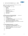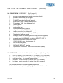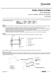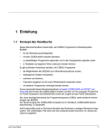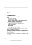
1
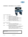
STEENBECK USER MANUAL 16mm 01-SERIES
Compact sized flatbed editors:
ST1201
ST1601
ST601
ST1901
2 plate, COMOPT sound.
for 600 meters / 2000 feet of film.
4 plate, COMOPT and 1 track SEPMAG sound.
for 600 meter / 2000 feet of film and perforated tape.
4 plate, COMOPT and 1 track SEPMAG sound.
for 600 meter / 2000 feet of film and perforated tape.
picture-sound shift system for 1 track.
6 plate, COMOPT and 2 tracks SEPMAG sound.
for 400 meter / 1300 feet of film and perforated tape.
Larger sized flatbed editors:
ST901
ST921
6 plate, COMOPT and 2 tracks SEPMAG sound.
for 600 meter / 2000 feet of film and perforated tape.
picture-sound shift system for 2 tracks.
6 or 8 plate version with 2 picture system.
standard with one COMOPT and 2 tracks SEPMAG sound.
depending on version from 350 meter / 1200 feet up to
600 meter / 2000 feet of film and perforated tape.
picture-sound shift system for 2 tracks.
8 plate version can have 4 plates of 600 meter/2000 feet.
Copyright © 1978 – 2013.
Steenbeck is a trademark.
No part of this manual may be reproduced without the prior written permission of Steenbeck.
Specifications, colours etc. are subject to change without notice. Images are an example.
V01-2013
16mm-01 serie
Table of contents user manual:
Section
page
0.0
Table of contents
1.0
Introduction
3
2.0
General data
3
3.0
Technical data :
3.1.1. introduction
3.1.2. film plates / film reels / cores
3.1.3 shrunken material
3.1.4 frictions
3.2
picture
3.3
sound
3.4
general technical information
4
4
4
4
5
5
6
Important safety and warranty information 4.1 safety
4.2 warranty
7
8
fig. 1
fig. 2
fig. 3
fig. 4
fig. 5
general overview
switch board
sound preamplifier section
fuse panel
drive deck overview
9
10
10
10
11
How to use the 16mm 01-Series:
5.1 general overview
5.2 switch board and pressure switches
5.3 sound preamplifier section
5.4 drive deck
5.5 fuse panel
5.6 connecting to mains power
5.7 threading film and sound tape
5.8 rewind
5.9 sound
12
12
12
13
13
14
14
15
15
Universal counter /display
Picture - sound shift system (ST601-ST901-ST921 only)
16
17
4.0
5.0
6.0
V01-2013
1-2
1
7.0
Connection loudspeakers and (optional) working lamp
8.0
Maintenance instructions : 8.1
8.2
8.3
8.4
8.5
8.6
8.7
8.8
8.9
8.10
8.11
9.0
List of fast and slow moving spare parts / options
24
10.0 Operation field table top: 10.1 ST601 ST1601
10.2 ST901 / ST1901
10.3 ST921
25
26
27
11.0 Adjustment picture lamp 16mm (all models)
28
12.0 Threading film and perforated magnetic sound (MAG) tape
ST1201
fig.12 picture only
fig.13 picture with sound
ST601 / 1601
fig.14 picture w/o sound / w MAG
fig.15 picture w sound
ST901 / 1901
fig.16 picture w/o sound / w MAG
fig.17 picture w sound
ST921
fig.18 picture w/o sound / w MAG
fig.19 picture L w sound / w MAG
29
29
30
30
31
31
32
32
Pictures ST1901 - ST921(S)
V01-2013
introduction
replacing picture lamp
replacing exciter/optical lamp
adjustment pressure arms picture
surface-coated mirrors
polygon and lens
screen
illumination system
frictions
general maintenance
adjustment guide ring 16mm
18
19
20
20
20
20
20
21
21
21-22
22
23
33
2
1.0 INTRODUCTION:
The 16mm 01-Series film editing, viewing and controlling tables, is for many years a
solid proven concept for e.g. film archives, film laboratories etc..
Working with this table is comfortable. With a minimum of physical effort the film can
be checked in a fast and accurate manner, the metadata is noted and the film is
prepared for possible scanning.
This manual shows the way to use all the possibilities of this 16mm 01-Series film
table.
Caution: since the introduction of the 01 series many electronically / mechanically
developments and improvements have been made. Be aware that the type number
never have been changed since and therefor new and/or old parts/electronics not
always been interchangeable.
Read this manual carefully before starting to work.
2.0 GENERAL DATA:
-
-
for 16mm film, with COMOPT (optical) sound. (COMMAG sound: optional)
2 plate version up to 8 plate with SEPMAG sound.
fast and accurate checking / viewing film.
halogen lamp 12 Volt / 100 watt.
high quality projection screen.
digital processor counter.
display for actual speed of the film (option ST200)
Sound system:
- each preamp with fader
- summing amp.: with treble, bass and master volume potentiometer
- ¼” head phone jack
- two way high quality speakers.
switchable sync speeds 24 and 25 f.p.s. (frames per second)
variable speed from 0 till 200 f.p.s. (approx.) (option ST200)
standard for film cores and 16mm film spools.
ground glass, back illuminated.
dimmer for working lamp (option ST57)
operating voltage selectable 100 – 240 Volt / 50 of 60Hz at 6 /10 Amp
V01-2013
3
3.0
TECHNICAL DATA:
3.1 DRIVE SYSTEM.
3.1.1 Introduction:
The Steenbeck 01-Series has a proven 1 motor drive technology.
The table runs smoothly, because of the famous Steenbeck ‘speed switch’.
This speed switch has fixed points for sync (synchronous 24 or 25 frames per second
f.p.s.) forward and reverse and has adjustable notches between sync en maximum
speed. (approx. 50 f.p.s., forward and reverse selectable by user).
The maximum speed can also be adjusted to approx. 200 f.p.s.
The maximum for both directions can be a little different.
3.1.2 Film plates / film reels / cores:
Depending on version the film plates are for approx. 400 meter / 1300 feet of film up
to 600 meter / 2000 feet of film with cores/bobbins according to DIN 15531.
Film reels for 16mm according DIN 15621 can be used, but use them carefully.
The winding tension of the plates can be adjusted (see section 8.9 – page 21)
3.1.3 Shrunken material:
The standard supplied sprocket rings are made to be used also for slightly shrunken
film material. If the film is in a bad condition (very stretched or shrunken) it is
advisable to change the sprocket ring at the polygon, otherwise the film can be
damaged.
For shrunken film with sound the COMOPT sprocket should also replaced by a
shrunken one (see E – page 23).
We also have sprockets for shrunken SEPMAG perforated tape.
See options for the correct stock numbers in case of ordering.
3.1.4 Frictions:
The frictions are fitted for use of film cores and film reels with square holes.
It is recommended to use film bobbins/cores of 100mm diameter.
When using film reels the film plates and film core centre should be removed.
The film reel is the placed in the square pin.
By film reel operation it will be necessary to readjust the film tension.
(see section 8.9)
It is not recommended to used film reels with core diameters less then 50mm.
V01-2013
4
3.2 PICTURE.
The rear screen projection method via an optical compensation system is done with
18-face revolving prism (polygon). With the high quality surface mirrors, optics and
screen material gives this a very brilliant, bright and sharp image.
The standard dimensions of the projection are 212 x 288 mm.
Accurate film transport is achieved by revolving sprockets .
The picture lamp can easily be replaced and adjusted.
In stand-still mode the light is automatically dimmed to prevent heat damages to the
film. The easy threading of film and perforated tape saves time and protect the film
from being damaged. (see pages 29 - 32 )
3.3 SOUND.
High quality sound reproduction is done by plug-in pre-amplifiers.
All sound is mono, however stereo SEPMAG is optional available.
COMMAG sound mono is optional available.
ST1201:
ST(1)601:
ST(1)901
ST921: 1x
COMOPT, mono
COMOPT, mono
COMOPT, mono
COMOPT, mono
1 track of SEPMAG (mono)
2 track of SEPMAG (mono)
2 track of SEPMAG (mono)
-summing amplifier with: treble / bass / master volume adjust.
head phone output with ¼” jack.
-2 loudspeakers 2 way, 2 x 30 watt.
The so called synchronize points for film and PE sound film (perforated tape) are
only available on request as an option.
V01-2013
5
3.4 GENERAL DATA.
Power:
Power consumption:
Switch on current:
The fuses (5x20mm)
1 phase 100 – 240 Volts - 50 / 60 Hz.
approx. 800 – 1000 W. (depending on version)
10 Amps. (at 230 V)
100 – 120 Volt
10 Amp T and 1 Amp T.
220 – 240 Volt
6,3 Amp T and 0,5 Amps T
The fuses can be found on the back side of the machine. (see fig. 4 page 10)
Important: all fuses in the Steenbeck 01-Series are T (slow blown) and
should never be replaced by F (fast blown) fuses.
Sizes of a complete table incl. monitor and speakers:
ST1201 – ST601 – ST1601 – ST1901; compact sized editors:
width
112 cm
working height
80 cm
depth, incl. monitor
99 cm
total height
126 cm
Weight 150 kg up to 170 kg.
ST901 – ST921; large sized editors:
width
working height
depth, incl. monitor
total height
Weight 210 kg up to 230 kg.
V01-2013
152 cm
80 cm
106 cm
126 cm
6
4.0
IMPORTANT SAFETY AND WARRANTY INFORMATION.
4.1
SAFETY:
The installation and maintenance should always be done by Steenbeck factory
engineers or an appointed /certified Steenbeck agent / dealer.
Of highest importance is a well-connected and safe power ground system.
This system has to be in a 100% condition, because of:
- the safety of the user of the Steenbeck 01-Series
- the risk of electronically malfunction both inside and outside the table.
- discharge of static electricity.
The 01-Series should always be placed in a dry room and free from dust.
The temperature should be between 5° C and 40° C (40°F 105°F)
Humidity should be between 30% to 70% (approx.).
A higher humidity can cause corrosion on electronic contacts.
Warning: never put drinks / liquids on the Steenbeck machine.
Liquid spill, when leaking into the machine, can cause great damage and can be
dangerous for its user.
Regularly clean the machine with the brush and the special cleaning wipes (blue is
for wet use and yellow is for dry cleaning). Never use steel cleaning tools.
Never open the machine.
If there is any mechanical or electronically alignment needed, these should be done
by a Steenbeck engineer or by Steenbeck trained staff.
It’s advised to use good trained staff to work with the Steenbeck machine.
It’s very important that this personnel has read and studied the user manual.
IMPORTANT:
There is always a personal danger related to the revolving sprockets.
Beware of this danger when having long hair, necklaces, bracelets,
long sleeves etc.
V01-2013
7
4.2
WARRANTY INFORMATION:
STEENBECK film machines are made with the best possible accuracy and precision.
Extensive runs and tests are done on the machine prior to shipment.
STEENBECK film machines are built to achieve maximum quality, reliability, and long
life resulting in a minimum of maintenance.
There is always the possibility that within the warranty period of 1 (one) year,
after purchasing the Steenbeck, a part is not working properly.
In such case, please contact the Steenbeck factory or your local Steenbeck
agent/dealer at once.
Defective parts will be repaired or replaced by Steenbeck.
Before replacing the part, Steenbeck has the right to check the part before
replacing it.
No warranty in case of:
-
the machine is used for a different purpose than what it was made for.
deliberate damage.
an untrained technician has worked at the machine.
defective projection or optical sound lamp, wire breakage.
damage the lacquer by use, bumping or cleaning with not advised solvent.
Defective parts should be send to the Steenbeck factory in Holland or the local
agent/dealer at cost and risk of the owner/user of the Steenbeck machine.
The costs for the repair or replacement of parts are in principle always
at cost of Steenbeck.
The Steenbeck factory always returns the parts free of charge. The replaced parts
are always property of Steenbeck .
If a Steenbeck engineer is required to take care of the warranty repairs or
replacements, all travelling and accommodation costs are for the owner/user of the
Steenbeck machine.
V01-2013
8
11
8
2
1
3
10
6
5
9
4
10
7
Fig.1
V01-2013
9
22
21
16
17 18
19
20
14
fig. 2
15
25 26
27
28
30
56
58
56
61
29
fig.3
57
60
59
fig.4
V01-2013
10
52
44
40
43
47
46
41
37
34
35
45
35
48
39
50
49
42
55
38
38
47
42
51
54
36
fig. 5
5.4
DRIVE DECK
34.
35.
36.
37.
38.
39.
40.
41.
42.
43.
44.
45.
46.
47.
48.
49.
50.
51.
52.
53.
54.
55.
OVERVIEW
(fig. 5)
polygon cover cap (support guide ring; not on photo)
pressure arm picture left and right
pressure arm sound left and right
COMOPT sprocket for film with sound
push button (red) to detach pressure arm
cover plate (lift when threating film)
framing picture
focus image
guide rollers film
optical sound reader COMOPT
magnetic head for COMMAG (optional)
tension roller, for film with sound
protection cap optical sound lamp (OPT. 2)
fly wheels to optimize sound
hexagon screws for adjusting picture lamp (see also page 28)
cover picture lamp
magnetic head for SEPMAG (or placing SEPOPT / OPT. 1)
switch for sound-shift system, not shown. ST601-901-921 only (see also page 18).
cap for lens and prism
screw bearing shaft plate pressure arm (see page 23)
SEPMAG / SEPOPT sprocket
upper prism / condensor (part of the illumination system)
V01-2013
11
5.0
HOW TO USE THE STEENBECK 16mm 01 - SERIES:
Read this section carefully, study all the possibilities and run some tests.
Make the most important actions your own.
5.1 GENERAL OVERVIEW: (fig. 1 page 9)
1
drive deck
2
friction left
3
friction right
4
ruler
5
ground glass (back lit), to check film
6
speed switch
7
sound preamplifier section
8
universal counter /display (fig. 15)
9
switch board
10
pressure switches
11
screen holder
12
13
5.2 SWITCH BOARD and PRESSURE SWITCHES:
(fig. 2 page 10)
Switches 16 t/m 19 are the so-called sub functions.
14
main power on / off switch
15
pilot lamp
16
on / off switch sound
17
on / off switch picture lamp
18
on / off switch 2nd picture lamp (ST921 only) or switch video lamp
19
on / off switch back light ground glass
20
rotary knob for dimmer working lamp (optional)
21
pressure switch for synchronous speed 24 or 25 f.p.s.
The selected speed is indicated by a green LED on the counter display
22
interlock: not in use since 2010
23
24
5.3 SOUND PREAMPLIFIER SECTION
(fig. 3 page 10)
25
pressure switch for optical sound lamp (OPT. 2)
26
pressure switch for 2nd optical lamp (SEPOPT – OPT. 1)
27
summing amplifier, with treble, bass and master volume control
28
headphone ¼” jack (mono)
Don’t use a head phone with less than 600 Ohm impedance
29
magnetic preamplifier
30
optical preamplifier
31
32
33
-
V01-2013
12
HOW TO USE THE STEENBECK 16mm 01-SERIES.
5.4
DRIVE DECK
34
35
36
37
38
39
40
41
42
43
44
45
46
47
48
49
50
51
52
53
54
55
OVERVIEW
(fig. 5 page 11)
polygon cover cap (support guide ring; not on photo)
pressure arm picture left and right
pressure arm sound left and right
COMOPT sprocket for film with sound
push button (red) to detach pressure arm
Cover plate (lift when threating film)
framing picture
focus image
guide rollers film
optical sound reader COMOPT
magnetic head for COMMAG (optional)
tension roller, for film with sound
protection cap optical sound lamp (OPT. 2)
fly wheels to optimize sound
hexagon screws for adjusting picture lamp (see also page 28)
cover picture lamp
magnetic head for SEPMAG (or placing SEPOPT / OPT. 1)
switch for sound-shift system, not shown.
ST601-901-921 only, see also page 18.
cap for lens and prism
screw bearing shaft plate pressure arm
SEPMAG / SEPOPT sprocket
upper prism / condensor (part of the illumination system)
5.5 FUSE PANEL: at the back ofthe right hand leg
56
57
58
59
60
(continued)
(fig. 4 page 10)
fuse 6,3 Amps T (220 / 240 volts) or 10 Amps T (110 / 120 volts)
fuse 0,5 Amps T for all voltages or 1 Amp T (110 / 120 volts)
pilot lamp fuses. (on when a fuses is blown)
Interlock (not in use with 01-Series, from 2010 onwards)
bi-phase (not in use with 01-Series, from 2010 onwards)
The fuses are located in a holder with bayonet mount.
If a fuse has blown, the pilot lamp (39 page 10) next tot his fuse will be on.
V01-2013
13
HOW TO USE THE STEENBECK 16mm 01-SERIES.
(continued)
5.6 connecting to mains power:
Connect the machine to the power network according to the instructions on page 5
with the supplied power cable. Make sure that this cable is well connected.
Always check the Voltage and Frequency mentioned on the type and serial number
plate (back side table).
Of great importance is a safe power ground system.
Switch the 01-Series on with the main switch (fig.2 #14 page 10), it shows a green
light.(15)
Only then switch on the sub functions (from 16 onwards).
Warning : before switching off the table, always switch off all the sub functions.
5.7 Threading film:
Thread 16mm film according to fig. 12 – 19 (pages 29 - 32 )
Attention: in order to prevent unnecessary wear, when threading film without sound,
never use the magnetic head (fig. 5 #50 – 44 page 11) and sprocket (37), and switch
off the sound (fig. 2 #16 page 10).
When the film has COMOPT or COMMAG sound, thread the film with sprocket (37)
in a way the tension roller (45) can move a little bit, this because too much tension
can damage the perforation.
Use the speed switch (fig 1 #6 page 9) to view the film.
While winding or rewinding from 0 to sync speed and sync, the speed is continuously
variable.
This makes it possible to view the film frame by frame.
When the framing is not correct it can be adjusted (fig. 5 #40 page 10).
Focus picture is adjustable (41).
Thread the 16mm film according the version.
Pages 29 - 32 show the way to thread film with and without sound.
Also shown are the threading of SEPMAG / SEPOPT.
V01-2013
14
HOW TO USE THE STEENBECK 16mm 01-SERIES.
(continued)
5.8 Rewind:
Don’t rewind the film as it is thread for viewing, because of the sprockets, older films
with bad splices and perforation can get damaged.
It’s advised to rewind the film always with a (Steenbeck) film rewinder.
The Steenbeck film rewinder can wind forward and backward and the speed can be
adjusted, even to very slow. This can be useful when it’s required to check or clean
the film by hand.
5.9 Sound:
The 16mm film can be viewed with optical (COMOPT) sound (COMMAG is optional)
and separate magnetic sound (SEPMAG).
See for threading film with COMOPT sound and SEPMAG sound pages 29 - 32.
Hints for optical sound:
-if optical is unused, it’s preamplifier fader should be set to zero position.
-avoid direct exposure of the optical sound reader by room light or table working
lamp. The light sensitive device in the sound reader may be influenced by this
exposure and causing extra audible noise like hum.
Adjustment of the volume with the fader halfway on the preamp first.
(page 10 #29 – 30)
Then the master volume control button (page 10 #27) in the mid .
Adjustment of the sound by treble and bass (page 10 #27)
Plug in a headphone with a ‘1/4”jack’ (page 10 #28).
When a headphone is used, the speakers are off.
Caution:
When the level of the headphone is to low, it’s caused by the impedance of the
headphone
V01-2013
15
6.0
Universal counter:
For ST1201 – ST1601 – ST1901 – 2nd counter ST921.
10
1
The Steenbeck universal counter is designed to measure film length (all formats) and
calculate the position and time information in common use.
Additionally, the universal counter may offer extra possibilities for more effective work
on your film rewind / film inspection table.
The counter / calculator functions are controlled by keys No. 1 – 10 (right to left)
1.
2.
3.
4.
5.
6.
7.
8.
9.
10.
frames
feet 35mm
feet 16mm
feet 8Smm
m / dm 35mm
m / dm 16mm
m / dm 8Smm
min / sec 25 FPS
min / sec 24 FPS
min / sec 18 FPS
counts and displays number of frames (max. 1.999.999)
displays film length in feet (16 frames = 1 foot)
displays film length in feet (40 frames = 1 foot)
displays film length in feet (72 frames = 1 foot)
displays film length in meters (1 meter = 52,630 frames)
displays film length in meters (1 meter = 131,200 frames)
displays film length in meters (1 meter = 236,200 frames)
displays elapsed time (1 second = 25 frames)
displays elapsed time (1 second = 24 frames)
displays elapsed time (1 second = 18 frames)
The two digits to the right always indicate numbers of frames.
The other digits show the counter value according to the chosen film format.
A red LED on the key indicates the activated display format.
The green LED indicates 24 or 25 frames per seconds sync speed of the editor.
Together with the keys you will find one switch and two pushbuttons on the counter
front panel.
Pushbutton C = Clear
Pushbutton HOLD
Switch DIST CTR
V01-2013
Counter is reset to ZERO.
Display is stopped at actual reading.
The counter keeps on counting. When releasing
Pushbutton , counter value is transferred to display.
Setting 1: distance counter on
Setting 0: distance counter off.
The distance counter is activated to measure partical
length or time values.
It can be reset to ZERO (C)
without effecting the main counter.
16
UNIVERSAL COUNTER PICTURE – SOUND SHIFT SYSTEM.
For ST601 - ST901 – ST921
D
B
A
C
D
The picture-sound synchronizer shows the shift of the sound tape
against the picture tape in positive and negative directions.
The range of display is ± 99.9 frames.
The shift of the sound tape is accurate tot 1/100 of a frame –
displaying are 1/10 of a frame.
A switch (A) makes two type of operation possible:
Switch position B:
As long as the switch 51 (fig. 5 page 11 and page 18) is pushed the picture – sound
shift runs continuously and can be stopped at any desired point.
Thus both tapes can (with a ST901-ST921) be brought together with perforation
correct at the sync point.
For ST601 one display is in function.
Switch position C:
With every touch of the switch 51 the sound tape be moved forward or backward by
exactly one frame, e.g.: to bring forward the sound by ten frames, the switch in a
forward position has to be momentarily pressed ten times.
By prolonged pressing the tape will carry on till the key is released.
The tape will now exactly to a perforation.
This will avoid the troublesome forward and backward pulling of the tape to
synchronize the two.
Push buttons D : reset display.
V01-2013
17
ST901
51
7.0 Connecting loudspeakers and (optional) working lamp:
All connections at the back of the frame.
Work light: (fig. )
Connector for 230V light max. 60 Watt.
The connection is as follows:
230 Volt:
pin 1 = phase + / pin 2 = phase - / pin 3 = ground
V01-2013
18
8.0
MAINTENANCE INSTRUCTIONS.
With the 01-Series delivered tools and spare parts which also can
be ordered separately:
part number:
Tools:
1 x wrench M2,5 to adjust frictions
1 x hexagon M5 to adjust picture lamp
Cleaning brush
Cleaning cloths set ( blue and yellow)
9962.0088.00
9962.0089.00
N000.0473.00
N000.0521.00
Spare parts:
2 x picture lamp 12V- 100W
1 x exciter/optical sound lamp
10 x fuse 6,3 Amp. T
(5 x 20 mm)
10 x fuse 0,5 Amp. T
(5 x 20 mm)
9956.1066.00
9956.1080.00
9956.0232.00
9956.0224.00
Various:
Dust cover
9962.1083.00
8.1 Introduction.
The Steenbeck 01-Series doesn’t need much maintenance. It depends on by whom,
how and under what circumstances the table is used. It’s advised to clean the table
every time it has been used with the supplied brush.
Clean the top of the table with the supplied cloth; Start cleaning with a moist
microfiber cloth (Blue) and dry it with the (Yellow ) dry cloth.
Caution: technical maintenance.
When the Steenbeck 01-Series is regularly in use (almost daily basis and more) the
maintenance needs to be done at least once a year by the dealer or Steenbeck
factory engineer. In this service the table will remain in a good condition.
To facilitate the operation the following instructions should be strictly
adhered to.
= only done by skilled staff
Before opening the machine be sure it is disconnected from the mains.
Only service engineers are authorized to do adjustment and technical maintenance.
The machine should only be operated with the side and front panels closed.
V01-2013
19
8.2 Replacing the picture lamp.
Lift cover plate (fig. 5 #49 page 11) beside the left pressure arm (fig. 5 #35 page 11).
Tilt back cap above picture lamp.
With the aid of the tool supplied the defective lamp is lifted out, and the new one is
carefully and gently pressed into the lamp socket.
ALWAYS readjust the newly inserted picture lamp.
NEVER touch the bulb with your fingers or clean it with a chemical alcohol.
8.3 Replacing of exciter lamp / optical sound lamp.
Remove protection cap (fig. 5 #46 page 11), loosen screw behind exciter lamp,
Before taken out the broken exciter lamp, check how it was placed. (lamp filament)
Take out old exciter lamp.
Replace new lamp the same as the broken came out.
Turn it in order to gain maximum illumination through the light gap, which is tested by
running film with optical sound.
Now tighten screw gently and put protection cap on.
8.4 Adjustment of pressure arms picture.
Feed two films strips through the sprocket and counter press arms.
Loosen screws at the bearing shaft plate (fig. 53 – page 23) and change pressure of
the arm so that both guide rollers are under the same pressure. Now tighten screws.
Loosen fixing screws of locking pin. Turn it, so that there is no play between film and
guide roller. Tighten fixing screws.
As pressure arms are adjusted for two thicknesses of film by manufacturer,
readjustment is only necessary after dismantling of the bearing shaft or the locking
pin.
Maintenance of optical parts.
8.5 Surface-coated mirrors.
Cleaning may only be done with a soft lens brush or lens cloth.
If the mirror is very dirty, detach it and clean carefully with clear water and cotton
wool. To avoid water stains the final touch is made with dry cotton wool.
8.6 Polygon and lens.
If the polygon is just a slightly soiled, open the pressure arms from the front and
clean with soft leather, cotton or special optician’s tissue.
For more thorough cleaning the support of the upper film guide support can be
removed (fig. 5 #34 page 11)
For this purpose remove at first the cap from the objective and prism (fig. 5 #52), than
loosen the 2 screws of the support and the upper film guide support can be taken off.
One has free access to the polygon now,
When remounting the support be sure the surface of the base is clean, otherwise the
upper film guide and sprocket ring do not line up.
The objective and prism can only be cleaned with the housing removed.
This should done by an Steenbeck engineer only because of optical alignment of the
projected image.
V01-2013
20
8.7 Screen.
The surface of the synthetic material is sensitive and can easily be scratched.
It is advisable to clean the screen regularly with a soft close.
If more cleaning becomes necessary, unscrew the screen from the screen holder
(11 – fig. 1) and clean it with water.
Caution:
-do not used any chemicals.
-pull the counter flat cable plug before removing the screen (holder).
8.8 illumination system.
The upper prism and its lenses (condenser 55 – fig. 5 page 11) can be unscrewed
and cleaned in the same manner as the revolving prism (polygon). See 8.5 – 8.6
When the prism / condenser has been removed the cold light mirror is visible.
This cold light mirror below the prism / condensor is held in place by a spring.
To remove the mirror, the table has to be opened and is reachable from the inside.
Pull the spring back and clean the mirror like a front surface coated mirror.
8.9 Frictions. (take up and supply units)
Frictions are operated by a motor via multiple V-belts.
It may become necessary to adjust the belt tension
after a certain operating time.
To achieve this, open frame at both sides and loosen
the corresponding tension roller arms with a wrench for
5mm bolts (8mm) and adjust the belt tension
The wind pull of the centre cores can be adjusted with
the little tension bolt inside the square mandrel (8mm)
of each friction.
For readjustment take off the film core. The tension bolt
can be turned then by an allen key (hexagon) 2.5mm
Steenbeck part number 9962.0088.00.
When turning anticlockwise the wind pull will be more
firm.
When turning clockwise the wind pull becomes looser.
The square 8mm mandrel must be arrested with a 8mm wrench.
(Steenbeck part number N000.0471.00 )
The wind pull should be checked by means of a 100 core and a spring scale.
In running mode (sync) of the table it should be as follows:
16mm picture:
approx. 0.8 – 1.0 N
/
80 – 100 grams.
16mm sound:
approx. 0.6 – 0.8 N
/
60 - 80 grams.
The core plate of the friction should not be greased or lubricated at the bottom.
The core axle fig. a should be greased a little bit.
The film plate support fig. b (plastic ring friction plate / inner ring film plate fig. c)
should have some Vaseline. (Steenbeck part number N000.0472.00)
V01-2013
21
core plate
fig. a
fig. b
fig. c
core axel
friction disc
plastic ring
core friction axel
film plate
inner ring
If metal film reels are used, the film plates and film core holders have to be taken off.
The film reel is then placed upon the remaining square mandrel.
This is only for 16mm film reels according ANSI PH 22.11 – 1981).
You might have to readjust the frictions because the weight of the film reels (see
above).
Caution: do not use a film reel with a core diameter less than 50 mm, as otherwise
the film material could be damaged.
8.10 General maintenance.
Remove dust, scrapping and film remainders from the machine DAILY.
After every approx. 100 hours of operation:
Clean all guide rollers, pressure arms/rollers and sprockets from possible remainders
of film and tape.
For cleaning the teeth of sprockets use a wooden stick.
Never use steel tools.
After every approx. 500 hours of operation:
Take off all rollers, clean rollers, shaft of rollers and axles with cleaning solvent.
Grease slightly the axles and shaft with a highly fluid oil.
After every approx. 1000 hours of operation:
Change motor oil in gear box as follows:
-open the middle panel of the chassis.
(near your knees when sitting behind the table)
-look for the drain screw at the bottom and the filling screw at the top of the gear box.
Loosen both screws. Empty the old oil into a container.
After tightening of the drain screw refill the box with new oil ATF, approx.. 22cc.
An elapsed time counter is available as an option. (Z50)
V01-2013
22
8.11 Adjustment guide ring 16mm.
53
E
20
Old film, even new film can differ in width.
The width “A” is normally set to 16mm – 0,2mm.
If the film is bending on the film gate the width must be adjusted.
To do this the cover “C” must be removed with a blade or anything similar.
The screw “B” should be turned anticlockwise with a two pin key.
If the film is loose on the gate (horizontal picture jitter), the screw “B” should
be turned clockwise.
Caution:
With old film be careful to make alignments.
Extra attention should be given when shrunken film is in the gate.
Try first to use one of the two picture pressure arm (20).
Make a careful test.
When this is not really helping the sprocket ring (E) should be replaced.
V01-2013
23
9.0 LIST OF FAST / SLOW MOVING PARTS 16mm 01-Series.
Fast moving parts:
Part number
9956.0224.00 fuse 0,5A T (slow)
9956.0232.00 fuse 6,3A T
9956.0230.00 fuse 2,0A T
9956.0227.00 fuse 1,0A T
9956.1066.00 picture lamp, 12 V / 100W
9956.1080.00 sound exciter lamp
Slow moving parts:
Part number:
3909.0804.01 picture roller, picture S16mm (12)
3909.0803.02 pressure roller, picture S16mm (11)
3208.0203.02 sound roller 16mm
(2)
3208.0201.02 pressure roller sound 16mm
(1)
3209.0201.04 Standard 16mm picture roller (3) on request only
3209.0202.01 Standard 16mm pressure roller (4) on request only
9953.0532.00 picture lamp socket
9955.0080.00 motor brush
OPTIONS:
ST57
table working lamp with dimmer
ST59
foot switch with control board
ST62
COMOPT 16mm red light/cyan reader
ST66
SEPOPT 16mm optical sound reader
ST66/3 COMMAG sound module 16mm
ST99/16 kit shrunken film 16mm 0,75-1,5%
ST170
ST177
Z50
N
F
N
F
F
N
(video)camera adaptor system*)
F
(video)camera adaptor system*) N16/S16 F
time elapsed counter
F
N=extendable by user or service engineer
V01-2013
F=factory installation only
ST175
ST191
ST192
ST200
Super 16 (1 picture)
N
extension board R
N
extension board L
N
variable speed control
F
including display
ST740 stereo sound SEPMAG
F
(for ST601 / ST1601)
ST741 stereo sound SEPMAG
F
for ST901 / ST1901
ST742 stereo sound SEPMAG ST921 F
nd
ST5001 counter 2 picture ST921
F
*)=only with camera advised / installed by Steenbeck.
24
10.0 OPERATION FIELD TABLE TOP.
10.1 SPEED SWITCH
ST601 / ST1601
fig.8
1. Speed selector (1) is activated by the speed control lever (2) in both directions.
-first notch right; sync speed forward.
-second notch right: winding speed forward, approx. 2/3 of maximum speed.
-first notch left; sync speed revers.
-second notch; winding speed revers, approx. 2/3 of maximum speed.
-final notch in both directions; maximum speed, approx. 200 frames per sec..
Between standstill and maximum speed forward or revers the speed is fully
variable by hand.
2. Speed control lever.
3. Clutch and brake switch for picture
(track 1)
4. Clutch and brake switch for sound Mag. 1
(track 2)
Clutch and brake switches 3 and 4 are used to (dis)-engage the corresponding
tapes from the drive.
Push button released:
tape engaged.
Push button suppressed:
tape disengaged.
Remark:
As soon as the table runs the switches 3 and 4 are enabled.
After the tables has stopped, these switches can be used again.
This feature is for:
- no damage can be done to material while the editor is in a full wind speed.
- no loss of sync by pushing clutch/brake switch accidentally during viewing.
V01-2013
25
OPERATION FIELD TABLE TOP.
10.2 SPEED SWITCH ST901 / ST1901
fig. 9
1. Speed selector (1) is activated by the speed control lever (2) in both directions.
-first notch right; sync speed forward.
-second notch right: winding speed forward, approx. 2/3 of maximum speed.
-first notch left; sync speed revers.
-second notch; winding speed revers, approx. 2/3 of maximum speed.
-final notch in both directions; maximum speed, approx. 200 frames per sec..
Between standstill and maximum speed forward or revers the speed is fully
variable by hand.
2. Speed control lever.
3. Clutch and brake switch for picture
(track 1)
4. Clutch and brake switch for sound Mag. 1
(track 2)
5. Clutch and brake switch for sound Mag. 2
(track 3)
Clutch and brake switches 3, 4 and 5 are used to (dis)-engage the corresponding
tapes from the drive.
Push button released:
tape engaged.
Push button suppressed:
tape disengaged.
Remark:
As soon as the table runs the switches 3, 4 and 5 are enabled.
After the tables has stopped, these switches can be used again.
This feature is for:
- no damage can be done to material while the editor is in a full wind speed.
- no loss of sync by pushing clutch/brake switch accidentally during viewing.
V01-2013
26
OPERATION FIELD TABLE TOP.
10.3 SPEED SWITCH ST921
fig.10
1. Speed selector (1) is activated by the speed control lever (2) in both directions.
-first notch right; sync speed forward.
-second notch right: winding speed forward, approx. 2/3 of maximum speed.
-first notch left; sync speed revers.
-second notch; winding speed revers, approx. 2/3 of maximum speed.
-final notch in both directions; maximum speed, approx. 200 frames per sec..
Between standstill and maximum speed forward or revers the speed is fully
variable by hand.
2. Speed control lever.
3. Clutch and brake switch for picture left
(track 1).
4. Clutch and brake switch for picture right
(track 2).
5. Clutch and brake switch for sound Mag.1 (track 3).
6. Clutch and brake switch for sound Mag.2 (track 4).
Clutch and brake switches 3, 4, 5 and 6) are used to (dis)-engage the
corresponding tapes from the drive.
Push button released:
tape engaged.
Push button suppressed:
tape disengaged.
Remark:
As soon as the table runs the switches 3, 4 , 5 and 6 are enabled.
After the tables has stopped, these switches can be used again.
This feature is for:
- no damage can be done to material while the editor is in a full wind speed.
- no loss of sync by pushing clutch/brake switch accidentally during viewing
V01-2013
27
11.0 ADJUSTMENT PICTURE LAMP 16MM.
ST921
ST1201 / ST1601 / ST1901
ST601 / ST901 / ST921
1.
Lighting aperture
2.
Picture screen
3.
Adjusting screw, vertical.
For uniform illumination at the top and bottom of the screen.
4.
Adjusting screw, focus.
Adjusting to minimal flickering
5.
Adjusting screw, horizontal.
For uniform illumination to the left and right of the screen.
6.
Cover plate for projection lamp. (12V – 100W only)
fig.11
Picture lamp adjustment should be carried out with machine in operation in sync
speed, but without film. It is advisable to start with the screws 3 and 5.
Use Hexagon 5mm Steenbeck part number 9962.0089.00.
V01-2013
28
ST1201: picture only
ST1201: picture with optical sound COMOPT or COMMAG
V01-2013
fig. 12
fig. 13
29
ST601-ST1601: picture w/o sound with SEPMAG
ST601-ST1601: picture with optical sound COMOPT or COMMAG
V01-2013
fig. 14
fig. 15
30
ST901-ST1901: picture w/o sound with SEPMAG
fig. 16
ST901-ST1901: picture with COMOPT or COMMAG fig. 17
V01-2013
31
ST921: picture w/o sound with SEPMAG
fig. 18
fig. 19
ST921: picture L with COMOPT / COMMAG / SEPMAG
V01-2013
32
ST921S
2 pictures
3 SEPMAG tracks
ST1901
STEENBECK B.V. (Ltd.)
Keizersveld 31, 5803 AM VENRAY. The Netherlands
Tel: +31 (0)478 63 03 00
Fax: +31 (0)478 69 00 07
[email protected]
www.steenbeck.com
V01-2013
33