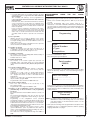
1
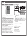
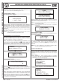
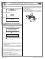
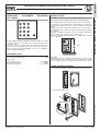
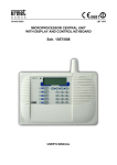
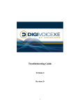
SECTION 2A
(REV.F)
CALL MODULE
Download from: www.urmetdomus.com Technical Manuals area.
SECTION CONTENTS
CAPABILITIES .................................................................................2
Description of the terminals ..........................................................2
TECHNICAL DATA...........................................................................3
FUNCTIONING.................................................................................3
Call for name selection .................................................................3
Code for call composition .............................................................3
Direct calls ....................................................................................3
Additional codes and functions .....................................................3
Programming of decoding boxes ..................................................4
PROGRAMMING..............................................................................4
Programming methods .................................................................4
Parameters ...................................................................................4
Programming using the Ref. 1038/56 Terminal ............................5
Local programming via keyboard..................................................6
TROUBLESHOOTING AND REPLACEMENT...............................12
Display ........................................................................................12
Electric lock ................................................................................12
Replacement procedure .............................................................12
ADDITIONAL ALPHABETIC KEYPAD Ref. 1038/74 .....................13
Technical data ............................................................................13
INSTALLATION ..............................................................................13
Flush mounted version ...............................................................13
ACCESSORY INSTALLATION ......................................................15
Flush mounted version with wall cover frame.............................15
Flush mounted version with rain hood ........................................15
Wall mounted version with case and hood .................................15
Gate semi-flushed panel accessories.........................................16
Examples of modular constructions............................................17
ENTRY OF THE LOCK RELEASE CODES .....................................7
Methods of insertion .....................................................................7
Insertion using the 1038/56 terminal ............................................7
Entry via keyboard ........................................................................8
Complete erasure .........................................................................8
NAME MANAGEMENT ....................................................................8
Management methods ..................................................................8
Management using personal computer and
Ref. 1038/56 terminal ...................................................................8
Management using the Ref. 1038/56 terminal..............................9
Management via keyboard .........................................................10
Complete erasure .......................................................................10
SOUND LEVEL ADJUSTMENT .....................................................11
DISPLAY CONTRAST ADJUSTMENT ..........................................11
ERROR CODES.............................................................................11
Errors during normal operation ...................................................11
Errors during installation/programming.......................................11
Self test.......................................................................................12
DIGIVOICE - Technical Manual
sec.2a −−−− 1
Ref. 1038/13
SINTHESI CALL MODULE WITH DIRECTORY Ref. 1038/13
CAPABILITIES - DESCRIPTION OF THE TERMINALS
SINTHESI CALL MODULE WITH DIRECTORY
SINTHESI CALL MODULE WITH DIRECTORY
Ref. 1038/13
1
2
3
8
4
9
+V 0V
D FA FB
FA2 FB2 +F 0F
MS
5
MP2
+V
0V
D FA1 FB1
MP1
Sch./Ref. 1038/13
S/N ......................
Data:....................
10
CONTR.
11
1
4
2
5
3
6
6
7
7
8
9
SE-
+V
SE+
SC
0V
SL
T2
S12
T1
0V
SP
S1
H
S2
P
12
0V
PH
MA
X
The Ref. 1038/13 Call Module is based on Sinthesi mechanics with
2 modules. Although it is not equipped with the embedding box and
related module-holder frame (which can be bought separately), it is
complete with anti-theft screw for security of installation.
CAPABILITIES
SINTHESI CALL MODULE
The Call Module comprises:
The Ref. 1038/13 Call Module with repertory provides the following
capabilities:
• Possibility of forwarding a house phone or video house phone call
(in combination with the Ref. 1745/70 TV camera unit).
• Automatic management of house phone and video house phone
traffic according to the number of voice lines available (1 or 2).
• Selection, using scroll keys and a 2-line, 16-character back-lit
alphanumeric display of the name to be called. Up to 740 separate
names are available.
• Direct selection, via keyboard, of an alphanumeric call code (in
combination with the Ref. 1038/74 Additional Alphabetic keyboard).
This means that up to 159999 separate call codes are available.
• Possibility of managing up to 2 direct call keys (in combination with
the Ref. 1145/11 or 1145/12 module) for calls to specific users or to
a main entrance switchboard.
• Up to 980 lock release codes divided into two categories: 240 codes
independent of the names, for general use, plus another 740 codes
associated to the individual names.
• Up to 7999 codes for special services.
• Impulse type lock release (free or with secrecy) with maintenance
current for timed driving (from 1 to 30 seconds) of a low absorption
electric lock.
• Acoustic and visible signaling of driving of the electric lock.
• Programmable call tone duration from 1 to 5 seconds.
• Differentiated generation of the call tone, continuous tone in the
case of main module, intermittent tone if a secondary module.
• ‘Call forwarded’ and ‘end of conversation’ acoustic signals.
• Adjustment of service and acoustic signal intensity.
• Interface for door open sensor.
• Possibility of programming the names using the Ref. 1038/56
programming Terminal; direct access to programming (for minor
modifications) from the external keyboard without having to use the
terminal.
• Auto-insertion function without the need for dedicated wiring.
• Provision for operation in 11 languages: Italian, French, English,
German, Spanish, Hebrew, Russian, Dutch, Turkish, Portuguese,
Polish.
2 −−−− sec.2a
MV
0
1
2
Two-module Sinthesi front.
Connector for programming using the Ref. 1038/56 Programming
Terminal.
3 Adjustable call module speaker volume.
4 Programming button (for use only when password is not known).
5 Alphanumeric display, two-rows, 16-characters, back-lit.
6 Yellow back-lit name selection buttons.
7 Green back-lit number pad buttons with yellow back-lit function
buttons: “Cancel” ‘X’, “Key” ‘
’ and “Call” ‘ ’.
8 Additional alphanumeric keyboard (1038/74) connector.
9 Extractable terminal strips for system connections (MP1, MP2,
MS).
10 Label with indication of the serial number (S/N) of the device.
11 Adjustable LCD contrast.
12 Extractable terminal strips for local auxiliary services (MA) and
video signal (MV).
DESCRIPTION OF THE TERMINALS
MP1 – Main terminal strip
+V
0V
D
FA1
FB1
Power supply positive (+24V)
Power supply and data line ground
Data line
Voice circuit 1 to conductor
Voice circuit 1 return conductor
MP2 – Main terminal strip
FA2
FB2
+F
0F
Voice circuit 2 to conductor
Voice circuit 2 return conductor
Voice circuit power supply positive (+33V)
Voice circuit ground
MS – Secondary terminal strip
+V
0V
D
FA
FB
Power supply positive (+24V)
Power supply and data line ground.
Data line
Voice circuit to conductor
Voice circuit return conductor
DIGIVOICE - Technical Manual
Ref. 1038/13
TECHNICAL DATA -FUNCTIONING
MA – Auxiliary terminal strip
PLEASE
SPEAK
Electric lock driving output - negative
Electric lock driving output - positive
Keys/contacts/buttons common
Input Key 2 for dedicated call
Input Key 1 for dedicated call
Door sensor input
Lock release code inhibition contact input
Postman key contact input
Main entrance locking button input
During the conversation, any lock release command will be highlighted
both audibly (3 beeps) and visibly with the following caption for 3
seconds:
DOOR
OPEN
MV – Video terminal strip
+V
SC
SL
S12
0V
S1
S2
0V
At the end of the conversation, (or if no reply is received after approx.
30 seconds), the name selection message is redisplayed automatically
accompanied by 3 beeps.
Ref. 1038/68 video relay box power supply
Ref. 1038/68 video relay drive output - riser
Ref. 1038/68 video relay drive output - local
Ref. 1038/68 video relay drive output - channels 1 and 2
Ref. 1038/68 video relay box ground
Ref. 1032/9 video relay drive output for channel 1
Ref. 1032/9 video relay drive output for channel 2
Ref. 1032/9 relay devices ground
CODE FOR CALL COMPOSITION
The code entered on the keyboard of the Call Module (and optionally
of the Ref. 1038/74 Additional Alphabetic Keyboard) is shown on the
display.
Pressing of each key is echoed by an audible signal:
TECHNICAL DATA
Power take-off in unitary loads:
Logic circuits
Logic p.s. voltage (+V/0V) :
Maximum current draw:
Voice circuits
Voice circuit p.s. voltage (+F/0F):
Operating temperature:
CALL TO:
23
15LU
15 ÷ 25.2Vdc
400mA
30 ÷ 36Vdc
-10 ÷ +50°C
FUNCTIONING
When the ‘ ’ key is pressed, the call is forwarded to the extension
with the code entered. The buzzer of the indoor set called is activated
for the time programmed (from 1 to 5 seconds) with a continuous
tone (Main Call Module) or intermittent tone (Secondary Call Module).
Three beeps confirm that the call has been forwarded. Subsequent
pressing of the ‘ ’ key extends the buzzer activation time.
When the ‘X’ cancellation key is pressed (in the case of an error during
entry of the code), the number on the display is cleared.
During the call, any lock release command will be indicated both
audibly (3 beeps) and visibly with the following caption for 3 seconds:
DOOR
OPEN
CALL FOR NAME SELECTION
In normal functioning, the repertory displays the message inviting the
user to select the name to be called:
Select NAME
with ↑ or ↓
Using the two scroll keys (6) it is possible to select the name to be
called. At this point, simply press the ‘ ’ key to send a call to the
name selected. The following message is displayed:
CALL
MADE
NOTE: if the user simply presses the ‘ ’ key when invited to select
the name, a call will be forwarded to the main entrance
switchboard.
Three confirmation beeps are emitted to indicate forwarding of the
call.
The buzzer of the indoor set called is activated for the time programmed
(from 1 to 5 seconds) with a continuous tone (Main Call Module) or
intermittent tone (Secondary Call Module).
The name selected is then redisplayed and remains visible for
approximately 30 seconds during which the buzzer of the indoor set
can be activated again simply pressing the ‘ ’ key again.
When the indoor set replies, the following prompt is displayed:
DIGIVOICE - Technical Manual
At the end of the conversation, (or if no reply is received after approx.
30 seconds), the name selection message is redisplayed automatically
accompanied by 3 beeps.
DIRECT CALLS
Two particular users can be called pressing the matching keys of
the Ref. 1145/12 Module if present. Any Ref. 1038/40 Main Entrance
Switchboard can be called simply pressing the ‘ ’ key (without
entering any code and without selecting a name) or alternatively
one of the two Ref. 1145/12 Module keys (if present and suitably
programmed).
ADDITIONAL CODES AND FUNCTIONS
The Call Module with Repertory is able to manage three separate
groups of codes:
• Call codes (1-JJJJ)
Identify the house phone or video house phone indoor set called;
during entry, codes consisting of less than four digits/letters must
NEVER be preceded by zeroes (for example, enter “12A” and not
“012A”). The call codes must always be terminated pressing the
‘ ’ key which activates forwarding of the code.
• Lock release codes (numeric ONLY:1-99999999)
Permit direct opening of the door by residents or by authorized
persons; these codes must always be preceded and followed by
pressing of the ‘
’ key. Initial pressing of the ‘
’ key prevents
sec.2a −−−− 3
SINTHESI CALL MODULE
SESE+
0V
T2
T1
SP
H
P
PH
SINTHESI CALL MODULE WITH DIRECTORY
SINTHESI CALL MODULE WITH DIRECTORY Ref. 1038/13
Ref. 1038/13
SINTHESI CALL MODULE WITH DIRECTORY Ref. 1038/13
PROGRAMMING
SINTHESI CALL MODULE WITH DIRECTORY
display of the lock release code in which the digits are replaced with
asterisks:
LOCK RELEASE CODE
********
The lock release codes can be inhibited in pre-established time
bands using an external timed switch that operates on the ‘H’ and
‘0V’ terminals.
• Special codes (1-JJJ)
Can be used to activate/deactivate auxiliary services such as the
stair lights, garden lights etc. Must always be preceded by a ‘0’
(which prevents display of the codes) and followed by pressing of
the ‘ ’ key:
SPECIAL CODE:
0***
These codes also make it possible to check the status of an input
showing this on the display with the ‘On’ or ‘OFF’ caption; for
example:
TERMINAL STATUS:
ON
For further information refer to the Ref. 1038/80 Special Decoding
box User Manual.
NOTE: in the case of an error during entry of any code, press the ‘X’
cancel key: the code shown on the display will be cleared.
PROGRAMMING OF DECODING BOXES
The Ref. 1038/13 Call Module with Repertory can be used by
the installation technician to program the decoding devices. For a
description of the parameters and programming methods, refer to the
decoding boxes User Manual.
In any case, if a parameter is programmed successfully, the display of
the module will show:
Programming
OK
Otherwise, the following message is displayed:
SINTHESI CALL MODULE
Programming
KO
PROGRAMMING
PROGRAMMING METHODS
The Call Module with Repertory can be programmed in three different
ways (in any case only when powered):
1) Programming using the Ref. 1038/56 Programming Terminal.
This programming method is recommended as the display of the
terminal facilitates the operations involved. The terminal may be
connected:
• Locally on the programming connector (2) to the Call Module to
be programmed.
• On any other Call Module or Main Entrance Switchboard
included in the system.
• On any Passive Plug (Ref. 1038/90) connected in the system.
4 −−−− sec.2a
2) Locally via keyboard without having to open the frame of the
Module. In this case, the configuration access password must be
known.
3) Locally via keyboard opening first of all the frame of the Call
Module to press the rear programming button (4).
PARAMETERS
The following parameters must be programmed:
A) The operating language
One of the listed languages can be selected in more consecutive
screen forms.
B) Description of the installation site
This is a 15-character string that must be used to assign the
Call Module a mnemonic name: e.g. ‘Entrance V. Roma’, ‘Corso
Venezia’, ‘Stair A’, ‘Stair B’. In actual fact, it is possible to insert
up to 30 characters but, in the fast search phase, only the first 15
will be shown. It is advisable therefore to restrict the name to 15
characters and to use the remaining characters for any additional
information.
C) 11 parameters to be configured
1) Type of Call station
It is possible to select between a Main Call station from which
calls can be made to all indoor sets or to the main entrance
switchboard and a Secondary call station from which calls can
be made only to the indoor sets of the specific riser.
2) Call station code
Each call station, whether Main or Secondary, is identified by a
code. The codes that can be assigned to a call station depend
however on whether this is Main or Secondary.
• If Main, the code will be between ‘1’ and ‘JJJ’;
• If Secondary, the code will be between ‘1’ and ‘JJ’ and will
indicate the riser to which it belongs.
3) Busy time
The busy time defines the minimum duration of a call (including
the time that passes between forwarding of the call and reply
by the user). To guarantee this minimum duration, the system
may – in the case of several concurrent calls - set one or more
call stations to ‘Busy’ status which is shown on the display with
the following message:
LINES BUSY
Please wait
When a Call Module has been set to Busy status, it cannot
be used to send calls (although it can be used to enter lock
release codes).
The busy time may be 10, 20, 30 or 40 seconds.
4) Electric lock management
Opening of the electric lock from an indoor set may be ‘Free’
(FREE) or ‘With Secrecy’ (‘SEC’): In the first case, the door
can be opened at any time; in the second case, it can be
opened only during the conversation.
The criteria according to which the various electric locks are
managed is important for correct functioning of the system.
ALWAYS COMPLY SCRUPULOUSLY WITH THE INSTRUCTIONS
GIVEN BELOW BECAUSE ONLY THE CONFIGURATIONS
DESCRIBED ARE PERMITTED.
• In installations with a single main call station and no
secondary call station, the call station can be configured
either with FREE LOCK RELEASE OR LOCK RELEASE
WITH SECRECY.
• In systems with several main call stations (in automatic
switching), all the call modules must be programmed with
LOCK RELEASE WITH SECRECY.
DIGIVOICE - Technical Manual
Ref. 1038/13
SINTHESI CALL MODULE WITH DIRECTORY Ref. 1038/13
PROGRAMMING
6) Duration of call ring
Indicates the duration of the call ring on the indoor set. It
is advisable to program the same value on all call stations.
Permissible values (in seconds) range from 1 to 5.
7) Number of voice lines
The number of voice lines (including Main and Secondary) in
the system must be specified.
Settable values are ‘1’ and ‘2’.
8) Buzzer Sound Level
The intensity of the acoustic signals (key pressed, call
forwarded, end of conversation beeps, etc.) can be adjusted
to 3 possible levels: Minimum (Min), Medium (Med), Maximum
(Max).
9) Code associated to Key T1
In the case of combination with a Ref. 1145/11 or -/12 module,
the code associated to pressing of the first key must be
specified.
If this key is to send a call to a specific Main Entrance
Switchboard - both during the day and night but not when
off – program the indoor set code of the Main Entrance
Switchboard.
If the key is to send a call to any switchboard present that is in
‘day A’ condition, program ‘0000’.
Programmable codes are between ‘0000’ and ‘JJJJ’.
10) Code associated to Key T2
This is the code associated to the second key of any
Ref. 1145/12 module.
Programmable codes range from ‘0000’ to ‘JJJJ’.
11) Saving of the Configuration Access Password and
(automatically) of the lock release code programming
password.
The password must be numeric ONLY and must consists of 4
digits.
The password programmed in this way can then be used
to access module configuration without having to open the
Sinthesi frame.
Programming of the configuration access password
automatically enables a second password that can be used to
program name and lock release codes. This second password
is derived from the first with an increment of 1. If, for example,
‘1234’ has been programmed, the name and lock release code
programming password will be ‘1235’.
The installation technician can therefore reveal to others
(system administrator, porter etc.) ONLY the name and lock
release code programming password avoiding any risk of
access also to configuration parameters.
The values that can be programmed range from 0001 to
9998.
DIGIVOICE - Technical Manual
USING
THE
Ref.
1038/56
Programming using the terminal must be carried out with the system
on.
• Switch on the terminal holding down the ‘ON’ key for at least 3
seconds.
• Insert the programming cable in the specific outlet (2) or alternatively – on another call Module, Main Entrance Switchboard
or Passive Plug. The terminal will be connected automatically to the
data line and the following message will be shown on the display for
3 seconds:
Programming
and then:
Find:
<Serial Number>
<Type>
<Acquisition>
SINTHESI CALL MODULE WITH DIRECTORY
5) Door open time
Indicates the time (in seconds) of duration of the electric
lock maintenance current. WARNING: when locks that do
not require latching current are used, ALWAYS set the lock
release time to zero.
In the case of low absorption locks ONLY, the door open time
can be set between 1 and 30 seconds.
PROGRAMMING
TERMINAL
• Select the <Serial Number> option.
The following message is displayed:
Serial number:
000000
Enter the serial number of the Call Module (given on the rear label
(10) at the S/N item), and press ↵ key. The following message is
displayed:
REP SN: uvwxyz
--------------Road . . . . . . . . . . . . .
At this point, the terminal is connected logically with the Call Module
with Repertory (REP) with the selected serial number (‘uvwxyz’). To
indicate that the module is in Maintenance status, the display of the
module will show:
MAINTENANCE
Please wait
NOTE: the module permits management of the electric lock also in
‘Maintenance’ status, both following entry of a lock release
code and activation of the main entrance button or of the
postman key contact.
• At this point, the following can be programmed: the description of the
installation site, the 11 configuration parameters and the operating
language divided into four pages:
sec.2a −−−− 5
SINTHESI CALL MODULE
• In systems with at least one secondary call station, the main
call station(s) must be programmed with LOCK RELEASE
WITH SECRECY.
The secondary call station(s) can be programmed as
required with FREE LOCK RELEASE OR LOCK RELEASE
WITH SECRECY.
In the first case, after a call from the main station, activation
of the lock release key on the indoor set called will cause
opening of the lock connected to the main call station and
of the lock connected to the secondary station on which that
indoor set depends.
In the second case, following a call from the main station,
activation of the lock release key on the indoor set called
will cause opening of the lock connected to the main calling
station only; a second call must then be made from the
secondary station in order to open the lock connected to
this.
Ref. 1038/13
SINTHESI CALL MODULE WITH DIRECTORY Ref. 1038/13
PROGRAMMING
(Page 1: Device recognized (REP) and its Serial Number, both nonmodifiable; Description of the installation site)
LOCAL PROGRAMMING VIA KEYBOARD
SINTHESI CALL MODULE WITH DIRECTORY
It is possible to access programming in 2 ways:
REP SN:uvwxyz
--------------Road . . . . . . . . . . . . .
INCORRECT
PASSWORD
(Page 2: Type, Code, Busy, Lock Management)
Type: P Cod:001
---------------Busy: 10 s
Lock Rel.: S-00 s
(Page 3: Call time, number of lines, Buzzer level)
Call:03 s
Lines: 1
Buzzer: 2
(Page 4: T1 and T2 key code assignment and Password)
Key 1:0000
Key2: 2:0000
Password: 9998
Language: English
• Program all the parameters using the alphanumeric keys, the ← and
→ keys to move, the ↵ key to confirm, the ‘sp’ key to switch between
the pre-established options.
• Press the → (or ←) key several times to move to the following page
<Names>
<Lock release>
<Program>
<Cancel><Exit>
SINTHESI CALL MODULE
a) If the configuration access password is known (the password
is factory set to ‘9998 ‘), enter ‘00’ followed by the 4-digit password
and the ‘ ’ key. If the password is incorrect, the following
message is displayed:
• Position the cursor on ‘Program’ and press ↵. The terminal writes
the data set in the memory of the Module and displays the result of
the write operation.
• Move to the page with the <Exit> option, position the cursor on this
and press ↵. At this point (and ONLY at this point), the Call Module
will exit Maintenance status and return to normal operation.
• Disconnect the programming cable and switch off the terminal
pressing the ‘OFF’ key for at least 3 seconds or if other call modules
connected to the system are to be programmed, repeat the steps
described above.
After the third unsuccessful attempt, entry of the password is
blocked for a period of time that depends on the number of
unsuccessful attempts:
N. unsuccesfull Wait time before
attempts
new password insertion
1
2
3
4
5
6
.
.
255
1 minute
2 minutes
3 minutes
.
.
252 minutes (above 4 hours)
b) If the password is not known, open the Sinthesi frame and press
the programming button (4).
After inserting the correct password - or after pressing the
programming button (4) – the following message is displayed for a
few seconds:
v1.0B 23/03/99
N.S.uvwxyz
The first indication refers to the SOFTWARE version (in this case
1.0) and to the maximum number of programmable lock release
codes: 240 (letter ‘B’ is displayed). These are followed by the
date of the version and the serial number of the device (S/N)
(‘uvwxyz’) coinciding with the serial number indicated on the rear
label (this information makes it possible to check the serial number
WITHOUT opening the Sinthesi frame).
The main menu is then displayed:
<LANGUAGE><CONFIG>
<ID><TEST><ESC>
a) Using the arrow keys, move the cursor to <LANGUAGE> and
press the ‘ ’ key to access the screen form used to select
operating language. The first screen form is as follows:
<ITA> <FRA> <ENG>
<DEU> <ESP> <
>
Move the cursor to language selected and press the ‘
Note: terminal Ref. 1038/56 can be set up only for English, Italian,
French, Spanish and German.
’ key.
b) To program the installation site description move the cursor to
<ID> and press the ‘ ’ key The following is displayed:
<Esc><Del><End>A
6 −−−− sec.2a
DIGIVOICE - Technical Manual
Ref. 1038/13
SINTHESI CALL MODULE WITH DIRECTORY Ref. 1038/13
ENTRY OF THE LOCK RELEASE CODES
Once entry has been completed, position the cursor in the reduced
<Esc><Del><End> menu. To do this, hold down the ↓ key until the
cursor is positioned on the ‘E’ of <Esc>. To confirm insertion of the
name, select the <End> item using the ↑ key and press the ‘ ’
key.
c) Moving the cursor to <CONFIG> and pressing the ‘ ’ key,
programming of the 11 configuration parameters distributed in
subsequent screen pages is accessed.
MODE TYPE:
<MAIN> <SECOND>
MODULE:CODE JJJ
JJJ
BUSY TIME:10s
<10><20><30><40>
keyboard is used). To correct any errors and restore the all data
saved press the ‘X’ key.
Once programming has been completed the main menu is
redisplayed:
<LANGUAGE><CONFIG>
<ID><TEST><ESC>
To restore normal functioning, select <ESC> and confirm with the
‘ ’ key.
NOTE: to interrupt programming at any time and return directly to
normal functioning simply press the ‘X’ key for more than
3 seconds. In this case the data entered so far will remain
however valid.
ENTRY OF THE LOCK RELEASE CODES
The Call Module makes it possible to insert up to 240 lock release
codes that are completely independent of the names, for general use.
These codes must be numeric only and each consist of a number of
digits that can be selected as required (between 1 and 8). Therefore
the permitted range is 1 to 99999999.
SINTHESI CALL MODULE WITH DIRECTORY
Use the ↑ and ↓ keys to scroll the characters that can be entered.
Press the ‘ ’ key to enter the character selected in the upper
line of the display. Although up to 30 characters can be entered
(starting from the time the 16th character is entered, the top line
scrolls progressively to the left), it is advisable to restrict insertion to
15 because only 15 will be displayed in the search from Terminal.
METHODS OF INSERTION
DOOR OPEN T. 0s
<-> <+> <OK>
CALL T.:3s
<1><2><3><4><5>
VOICE LINES:1
<1> <2>
BUZZER MED.LEV
<MIN><MED><MAX>
KEY 1:0000
0000
KEY 2:0000
0000
PASSWORD: 9998
9998
In all the screen pages, the programming method is identical:
• Using the arrows, move the cursor to the option selected and then
press the ‘ ’ key to confirm and move to the next screen page.
• In screen pages in which a code must be inserted, use the numeric
keys (and alphabetic keys if the Ref. 1038/74 additional alphabetic
DIGIVOICE - Technical Manual
The lock release codes can be inserted:
1) Using the Ref. 1038/56 Programming Terminal connected locally
or at any other point of the installation.
2) Locally from keyboard. In this case, the password for programming
of the names and lock release codes must be known (this is
DIFFERENT from the configuration access password).
INSERTION USING THE 1038/56 TERMINAL
After establishing a logical connection with the call Module concerned
(see description in ‘PROGRAMMING WITH THE 1038/56 TERMINAL),
move to the following page:
<Names>
<Lock release>
<Program>
<Cancel><Exit>
• Select <Lock release> and press ↵.
The first 3 lock release codes will be displayed:
Lockrel001:00000000
Lockrel002:00000000
Lockrel003:00000000
<P><S><OK><ESC>
• Enter the code(s) required and then, using the ← and → keys move
to the <OK> command and press ↵.
WARNING: THE 3 CODES ARE EFFECTIVELY SAVED IN THE
CALL MODULE ONLY FOLLOWING CONFIRMATION WITH THE
<OK> COMMAND. Saving is confirmed visibly.
• To access the three subsequent codes select the <S> command
and press ↵. Alternatively, to access the three previous codes select
<P> and press ↵ .
sec.2a −−−− 7
SINTHESI CALL MODULE
LOCK RELEASE TYPES:
<FREE> <SEC>
Ref. 1038/13
SINTHESI CALL MODULE WITH DIRECTORY
SINTHESI CALL MODULE WITH DIRECTORY Ref. 1038/13
NAME MANAGEMENT
• Once the codes have been programmed, select <EXIT> and press
↵ and then the ← key to move to the previous page, select <Exit>
and press ↵.
• Disconnect the programming cable and switch off the terminal
pressing the ‘OFF’ key for at least 3 seconds or if the same lock
release codes have to be programmed on another call module
connected in the system repeat the steps described above.
NOTE: to delete a lock release code, reprogram this to ‘00000000’.
ENTRY VIA KEYBOARD
• Enter ‘00’ followed by the 4-digit password (for programming of the
names and lock release codes) and by the ‘ ’ key. If the password
is incorrect, the following message is displayed:
INCORRECT
PASSWORD
After the third unsuccessful attempt, entry of the password is blocked
for a period of time that depends on the number of unsuccessful
attempts:
No. unsuccessful
attempts
Wait time before
new password insertion
1
2
3
4
5
6
1 minute
2 minutes
3 minutes
•
•
•
•
255
252 minutes (above 4 hours)
Once the password has been entered correctly the display will show:
<Names>
<Lock release><Esc>
• Select <Lock release> and press ‘ ’. The first page with the first
two lock release codes will be displayed:
Lockrel001:00000000
Lockrel002:00000000
SINTHESI CALL MODULE
• Enter the lock release code and then confirm with the ‘ ’ key.
• Use the Arrows to check the codes already inserted and to move to
the new codes.
• To exit the code entry phase and return to normal functioning press
the ‘X’ key for at least 3 seconds.
NOTE 1: instead of scrolling all the codes with the Arrow keys, it is
possible to find the first free space holding down the ‘ ’
key for at least 3 seconds.
NOTE 2: to delete a lock release code, reprogram this to ‘00000000’.
<LANGUAGE><CONFIG>
<ID><TEST><ESC>
• On the keyboard press the ‘
display will show:
’ key and ‘5’ at the same time. The
Erase ALL?
<Y> <N>
• Answering ‘YES’, all the Lock Release Codes and all the Names
(see below) stored in the device will be deleted. Answering ‘No’,
another two prompts will be displayed for confirmation of ONLY the
Names or ONLY the Lock Release Codes:
Erase names?
<Y> <N>
Erase lock release?
<Y> <N>
• Answering ‘No’ to the first prompt and ‘Yes to the second, ONLY the
Lock release Codes will be deleted.
NAME MANAGEMENT
It is possible to enter up to 740 names.
Each name includes the following information:
• Name of the user (maximum 32 alphanumeric characters distributed
on two 16-character lines).
• User code, alphanumeric (between ‘1’ and ‘JJJJ’).
• Lock release code, numeric only (between ‘1’ and ‘99999999’).
It is possible to proceed in such a way that several names (different
from each other) correspond to the same call (in the case of several
people living in the same apartment).
If the call code is to be displayed beside the name, simply save the call
code also in the 32 characters dedicated to user name.
MANAGEMENT METHODS
Names can be managed:
1) Using a Personal Computer and the Ref. 1038/56 Programming
terminal.
2) Using the Ref. 1038/56 Programming Terminal, connected locally
or at any other point of the installation, mainly for modifications,
cancellations and short entries
3) Locally, from keyboard, mainly for modifications, cancellations and
short entries. In this case, the password for programming of the
names and lock release codes must be known (this is DIFFERENT
from the configuration access password).
MANAGEMENT USING PERSONAL COMPUTER AND
1038/56 TERMINAL
COMPLETE ERASURE
In some cases, it may be useful to delete all the lock release codes
inserted (for example to reinstall the same device in another building).
Complete erasure of the lock release codes is possible only using the
keyboard:
• Enter ‘00’ followed by the 4-digit password for access to the
configuration (NOT that for lock release code management). The
main menu is displayed:
8 −−−− sec.2a
The best way to manage the names is to use the DVOICE Personal
Computer programs specifically designed to simplify insertion and
maintenance of the names of one or more sites. The DVOICE program
can be downloaded free of charge from the Urmet Domus Internet site
(http://www.urmetdomus.com).
The installation technician (or building administrator) may therefore
proceed:
DIGIVOICE - Technical Manual
Ref. 1038/13
SINTHESI CALL MODULE WITH DIRECTORY Ref. 1038/13
NAME MANAGEMENT
The various operations are described in detail below.
SAVING OF THE DATABASE ON THE PC
Using the DVOICE program, create a new site on your PC and save
the names of the residents together with any other relative information
(such as for example the lock release codes). For further information,
refer to the DVOICE program.
TRANSFER OF THE DATABASE FROM PC TO THE 1038/56
TERMINAL
• Connect the programming Terminal to the selected serial port of the
PC using the specific cable provided.
• set the DVOICE program to download the Database of the site on
the Terminal.
• Switch on the terminal. The following message is displayed:
To program
connect cable
<Configur.>
<Database> <PC>
• Select <PC> and press ↵. The following message is displayed:
<PC-TP>
<TP-PC>
<Exit>
• Select the <PC-TP> item, press ↵ and answer YES to the
subsequent confirmation prompt: transfer of the Database from PC
to Terminal will start.
• On completion of transfer, return to the main page, switch off the
terminal and disconnect the cable from the PC.
CHECKING AND MODIFICATION OF THE DATABASE
Once the names Database has been loaded on the terminal, it can be
examined and modified. To do this, access the <Database> item from
the main page and then select one of the possible options:
<Display>
<Insert>
<Modify>
<Cancel><Exit>
• Select <Names> and press ↵. The name Management menu is
displayed:
<Insert>
<Modify>
<Cancel><Exit>
<REP-TP><TP-REP>
• Select <TP-REP>, press ↵ and answer YES to the subsequent
confirmation prompt: transfer of the Database from the Terminal to
the Module selected is started.
• Once transfer has been completed disconnect the cable and switch
off the terminal pressing the ‘OFF’ key for at least 3 seconds, or if
the same database is to be programmed on another call module in
the system repeat the steps described above.
NOTE: in the case of a database with many names, transfer may
take a number of minutes. A horizontal square bar will indicate
state of completion.
TRANSFER OF A NAMES DATABASE FROM ONE CALL MODULE
TO ANOTHER (OR TO A PC)
To ‘copy’ the names from one call Module to another, use the Terminal.
Establish a logical connection with the first Module (that from which
the names are to be copied) and select first of all <Names> and then
<REP-TP>: the names database will be copied on the terminal. At this
point, it can be downloaded on another call module or, changing the
cable of the Terminal, on PC.
SINTHESI CALL MODULE WITH DIRECTORY
• To save the names of a site on his own PC.
• Transfer the database of names from the PC to the 1038/56
Programming Terminal.
• Inject the database of names in one or more Call Modules of the site
(connecting the terminal at any point of the site).
MANAGEMENT USING THE 1038/56 TERMINAL
After establishing a logical connection with the Call Module concerned
(see description in PROGRAMMING WITH THE 1038/56’ TERMINAL),
move to the page:
<Names>
<Lock release>
<Program>
<Cancel><Exit>
Select <Names> and press ↵. The name Management menu is
displayed:
<Insert>
<Modify>
<Cancel><Exit>
<REP-TP><TP-REP>
TRANSFER OF THE DATABASE FROM THE 1038/56 TERMINAL
TO ONE OR MORE 1038/13 CALL MODULES
• After establishing the logical connection with the Call Module
concerned (see description in the ‘PROGRAMMING USING THE
1038/56 TERMINAL paragraph’), go to the following page:
<Names>
<Lock release>
<Program>
<Cancel><Exit>
DIGIVOICE - Technical Manual
_
Code:0000
Lock rel.:00000000
Enter the Name, on a maximum of 2 lines of 16 characters each for
a total of 32 characters and press ↵. Enter the call code (between
‘1’ and ‘JJJJ’) and the lock release code associated to the name
(numeric only, between 1 and 99999999). When the specific prompt is
displayed, confirm.
sec.2a −−−− 9
SINTHESI CALL MODULE
INSERTION OF A NAME
Select <Insert>. The following message is displayed:
Ref. 1038/13
SINTHESI CALL MODULE WITH DIRECTORY Ref. 1038/13
NAME MANAGEMENT
SINTHESI CALL MODULE WITH DIRECTORY
Continue in this way inserting all the names. At this point, press the
<Esc> key to return to the Name Management menu.
CANCEL/MODIFY A NAME
Selecting <Cancel> or <Modify> from the name Management menu,
the following prompt is displayed:
Select the
name with the
← and → keys
Scroll the names until that to be deleted/modified is shown. WARNING:
during scrolling, only the first 16 characters of each name are
displayed. When the name concerned has been found, stop without
pressing any key; after approx. 3 seconds, the remaining 16 characters
of the name and the other parameters associated with these will be
displayed.
To delete, press ↵ and confirm. To modify, make the changes required
then press ↵ and confirm.
NOTE: when a name is deleted, any associated lock release code is
automatically deleted together with the name.
MANAGEMENT VIA KEYBOARD
This type of programming can be used as an alternative method to
that described above only for minor operations such as for example
insertion, modification or deletion of a single name.
Enter ‘00’ followed by the 4-digit password (for programming of the
names and lock release code) and by the ‘ ’ key. If the password
is incorrect, an error message will be output (for further details see
the paragraph on insertion of lock release codes using the keyboard).
Once the correct password has been inserted, the display will show:
<Names>
<Lock release><Esc>
Select <Names> and press ‘ ’. The Name Management menu will be
displayed from which to access all the functions:
<ADD> <CAN>
<MODIFY> <ESC>
INSERTION OF A NAME
Selecting <ADD>, the following is displayed:
SINTHESI CALL MODULE
<Esc><Del><End>A
Use the ↑ and ↓ keys to scroll the characters that can be entered.
Press the ‘ ’ key to enter the character selected in the upper line of
the display; starting from the 16th character of the name, the upper
line will be gradually shifted to the left, It is possible to insert up to 32
characters.
Once entry has been completed, position the cursor in the reduced
<Esc><Del><End> menu. To do this, hold down the ↓ key until the
cursor is positioned on the ‘E’ of <Esc>. To confirm insertion of the
name, select the <End> item using the ↑ key and press the ‘ ’ key.
Continue as described above to insert the call code (between ‘1’ and
‘JJJJ’) and the lock release code associated to the name (numeric
only, between 1 and 99999999):
10 −−−− sec.2a
Code:
<Esc><Del><End>0
Lock rel:00000000
<Esc><Del><End>0
Any errors during entry can be corrected selecting the <Del> item,
which deletes the last character inserted. Use <Esc> to abandon the
operation without saving the data entered.
NOTE 1: if the name inserted is already present in the memory, an
error message is output.
NOTE 2: if the code inserted is present in the memory, a confirmation
is requested:
Code present
Confirm? <Y><N>
CANCEL/MODIFY A NAME
Selecting <DEL> or <MODIFY> from the name Management menu,
the following is displayed:
FIND NAME
WITH ↑ OR ↓
Using the ↑ or ↓ keys, scroll the names present until that to be deleted
or modified is reached. Press the ‘ ’ key and delete the name
(after confirmation) or modify this (proceeding as described above for
insertion).
NOTE 1: if a name is deleted, any associated lock release code is
automatically deleted together with the name.
COMPLETE ERASURE
In some cases, it may be useful to delete all the lock release codes
inserted (for example to reinstall the same device in another building).
Complete erasure of the lock release codes is possible only using the
keyboard.
From Terminal
• After establishing a logical connection with the call Module
concerned (see description in ‘PROGRAMMING WITH THE 1038/56
TERMINAL), move to the following page:
<Names>
<Lock release>
<Program>
<Cancel><Exit>
• Select <Names> and press ↵. The name Management menu is
displayed:
<Insert>
<Modify>
<Cancel><Exit>
<REP-TP><TP-REP>
DIGIVOICE - Technical Manual
Ref. 1038/13
SINTHESI CALL MODULE WITH DIRECTORY Ref. 1038/13
SOUND LEVEL ADJUSTMENT - DISPLAY CONTRAST ADJUSTMENT - ERROR CODES
Cancel
entire
repertory?
<No> <Yes>
where ‘entire’ means however deletion of the Names ONLY (and not
of Lock release Codes). Selecting ‘YES’ and confirming with the ↵
key all the Names will be deleted.
From keyboard
• Enter ‘00’ followed by the 4-digit password for configuration access
(NOT the name management password). The main menu is
displayed:
<LANGUAGE><CONFIG>
<ID><TEST><ESC>
• On the keyboard, press the ‘
display will show:
’ and ‘5’ keys at the same time. The
Erase ALL?
<Y> <N>
• Answering ‘YES’, all the Names and all the Lock Release Codes
stored in the device will be deleted. Answering ‘No’, another two
prompts will be displayed for confirmation of ONLY the Names or
ONLY the Lock Release Codes:
Erase names?
<Y> <N>
Erase lock rel?
<S> <N>Y
ERROR CODES
Various types of error codes are put on the display.
ERRORS DURING NORMAL OPERATION
Call to a non-existent user:
ERROR
NON EXISTENT
Call from a secondary call module to a user of another riser:
RISER
ERROR
At least one key is jammed:
KEYBOARD
JAMMED
Door lock release code incorrect or disabled:
SINTHESI CALL MODULE WITH DIRECTORY
• Press ← key for 3 seconds. The following prompt is displayed:
LOCK REL.
NON-EXIST
ERRORS DURING INSTALLATION/PROGRAMMING
No signal on data line (terminal ‘D’ not connected or signal missing):
DATA LINE
ERROR
Insertion of an incorrect Password:
• Answering ‘YES’ to the first prompt, ONLY the Names will be
deleted.
SOUND LEVEL ADJUSTMENT
The sound level towards the indoor set called is factory set and does
not require adjustment.
The sound level towards the outside is factory set to a medium value.
To modify this, use a screwdriver on adjustment (3).
PASSWORD
INCORRECT
Attempt to insert a name already present in the memory:
ERROR
NAME PRESENT
DISPLAY CONTRAST ADJUSTMENT
Display contrast is factory set to an optimal level. It can however be
modified using a screwdriver on the related adjustment (11).
ERROR
MEMORY FULL
Attempt to modify or delete a name with the memory empty:
ERROR
MEMORY EMPTY
DIGIVOICE - Technical Manual
sec.2a −−−− 11
SINTHESI CALL MODULE
Attempt to insert a name with the memory full:
Ref. 1038/13
SINTHESI CALL MODULE WITH DIRECTORY Ref. 1038/13
TROUBLESHOOTING AND REPLACEMENT
SELF TEST
ERROR
EPROM MISSING
ERROR
EEPROM
Name memory fault:
1
Configuration memory fault:
19
70
W 0
E 2.
M V.
SINTHESI CALL MODULE WITH DIRECTORY
Configuration memory not present:
circuit paying particular attention to the direction of insertion (notch
on the body of the component and on the socket); replace integrated
circuit MEW 7019, taking care to orient it correctly on installation.
• Re-place the rear cover.
• Power on the new Call Module.
WARNING: after replacing the memory, the serial number of the
new call Module automatically becomes that of the old Module:
remember to modify the indications on the rear label (10) by hand.
U3
ERROR
FLASH
TROUBLESHOOTING AND REPLACEMENT
DISPLAY
In the case of problems with the display, check first of all that contrast
is correctly set, using the rear adjustment (11).
A further check can also be carried out accessing – by entering the
configuration password or pressing the rear key – the main menu:
<LANG.><CONFIG>
<ID><TEST><ESC>
Select <TEST> and press the ‘
displayed:
’ key. Check that the control figure is
At this point, the matching character is displayed for each key pressed.
Press the ‘ ’ key, to return to the previous menu and then select
<ESC> to restore normal functioning.
SINTHESI CALL MODULE
ELECTRIC LOCK
In the case in which the electric lock fails to open, the cause can be
quickly traced:
• If the module emits a beep and the electric lock does not open, the
fault is in the section from the module to the electric lock or in the
module drive circuitry.
• If the module not only fails to open the electric lock but does not
even emit a beep, this means that the lock release command is
not received from the module: the fault is located on the indoor set
side.
REPLACEMENT PROCEDURE
In the case of a fault in the module, replace the entire module.
If many lock release codes have been programmed, it is possible to
remove the integrated circuit on which the codes are stored and to
re-insert this in the new module.
The name memory can be replaced in the same way.
• Cut off the power to the old Ref. 1038/13 Call Module.
• Remove the rear cover applying a light pressure on the side hooks.
• Remove the U3 and MEW 7019 integrated circuit.
• Remove the rear cover of the new module; replace the U3 integrated
12 −−−− sec.2a
DIGIVOICE - Technical Manual
Ref. 1038/13
SINTHESI CALL MODULE WITH DIRECTORY Ref. 1038/13
ADDITIONAL ALPHABETIC KEYBOARD Ref. 1038/74 - INSTALLATION
ALPHABETIC
KEYBOARD
INSTALLATION
WARNING: for wiring and the maximum permissible distances,
follow the instructions given in the section 1 of this manual.
A
B
C
D
E
F
G
H
I
X
J
The Call Module must be installed on Sinthesi frame (not provided).
The anti-theft screw provided must be used instead of the normal screw
furnished with the Sinthesi frame in order to guarantee installation
security.
Calling module with repertory Ref. 1038/13 can be used alone or
in combination with a camera unit and/or alphabet keyboard add-on
Ref. 1038/74.
Examples of modular constructions using 2 or 3 module holder frames
with respective flush-mounting boxes are shown below
The door unit module should be installed at a height of approximately
1.55 ÷ 1.60 metres.
The Ref 1038/74 Additional Alphabetic Keyboard makes it possible
to introduce letters of the alphabet in the call code and special code
composition phase.
The device must be combined with a Ref. 1038/13 Call Module to
which it is connected using the specific connection cable. In any case,
the device must be positioned BELOW (or at the most to the SIDE) of
the Ref. 1038/13 Call Module).
1
2
3
4
5
6
7
8
9
X
0
h = 1,55 ÷ 1,60 m
TECHNICAL DATA
Power take-off in unitary loads:
Logic circuits
Power supply voltage:
Power take-off when idle:
Operating temperature:
3LU
15 ÷ 25.2Vdc
~27mA
-10 ÷ +50°C
SINTHESI CALL MODULE WITH DIRECTORY
ADDITIONAL
Ref. 1038/74
Important
The module should not be illuminated from behind to make the calling
module display easier to read. Never direct the module towards strong
sources of light (e.g. the sun, lampposts, light bulbs, flashes or glare).
FLUSH-MOUNTED VERSION
• Fit the flush mounting box in line with the wall: it must not project.
• Fit the module holder frame.
SINTHESI CALL MODULE
A
4 mm
DIGIVOICE - Technical Manual
sec.2a −−−− 13
Ref. 1038/13
SINTHESI CALL MODULE WITH DIRECTORY Ref. 1038/13
INSTALLATION
Purchase flush-mounting boxes, frames and module holders separately
for wall mounting. The product codes (according to number of modules)
are:
NUMBER
OF MODULES
2
3
4
FLUSH-MOUNTING
BOX
1145/52
1145/53
1145/54
FRAMES AND MODULE
HOLDERS
1145/62
1145/63
1145/64
Refer to “Technical product manual - Door phone and video door phone
systems”, “Sinthesi panels” section for dimensions and additional
details on these products.
• Turn the frame round and connect wires.
J2
SINTHESI CALL MODULE WITH DIRECTORY
• Fit the module in the frame.
2
GT 3
GT 4
GT
0~ ~
12
J2
2
GT 3
GT 4
GT
0~ ~
12
• Adjust correct perpendicularity of the panel.
Close the frame and fasten the screw A.
Position the panel on the frame.
Fasten screw B on screw A.
A
SINTHESI CALL MODULE
B
A
A
B
14 −−−− sec.2a
B
A
DIGIVOICE - Technical Manual
Ref. 1038/13
ACCESSORY INSTALLATION
ACCESSORY INSTALLATION
WALL-MOUNTED VERSION WITH CASE AND HOOD
FLUSH-MOUNTED VERSION WITH WALL COVER
FRAME
The case and hood is provided with frame and module holder. The
available models and the dimensions are shown in “Technical product
manual - door phone and video door phone systems” section “Sinthesi
Panels”.
Fasten the hood to the wall by means of three bolts.
Arrange the hole for passing the wires through the lower area of the
casing and the head.
The wall cover frames are used to conceal possible irregularity of the
wall surrounding the flush-mounting box. The available models and the
dimensions are shown in “Technical product manual - door phone and
video door phone systems” section “Sinthesi Panel”.
Embed the flush mounting box in the wall, position the wall cover frame
and fasten the module holder lower screw.
Frame fastening is completed by tightening the upper frame screw
last.
Fit the modules in the frame then position the panel.
A
SINTHESI CALL MODULE WITH DIRECTORY
SINTHESI CALL MODULE WITH DIRECTORY Ref. 1038/13
4 mm
FLUSH-MOUNTED VERSION WITH RAIN HOOD
Rain hoods are used to protect the calling module from the weather.
The available models and the dimensions are shown in “Technical
product manual - door phone and video door phone systems” section
“Sinthesi Panels”.
Embed the flush mounting box in the wall, position the waterproof hood
and fasten the module holder lower head.
Hood fastening is completed by tightening the upper frame screw last.
A
SINTHESI CALL MODULE
A
A
4 mm
DIGIVOICE - Technical Manual
sec.2a −−−− 15
Ref. 1038/13
SINTHESI CALL MODULE WITH DIRECTORY
SINTHESI CALL MODULE WITH DIRECTORY Ref. 1038/13
ACCESSORY INSTALLATION
GATE SEMI-FLUSHED PANEL ACCESSORIES
Fit the modules on the frame.
Cases and hood for gate pillar installation are suitable for vertical
installation on a gate pillar.
The available models and dimensions are shown in “Technical product
manual door phone and video door phone systems” section “Sinthesi
Panels”.
Drill a hole dimensioned as shown on the provided template in the
pillar and arrange the case on the pillar.
WARNING: Eliminate a crossbar with cutters to fit double modules.
To fasten the case:
a Push the screw to the bottom of the box with a screwdriver.
b Push the screw outwards with a screwdriver.
c Fasten the screw.
A
C
SINTHESI CALL MODULE
B
16 −−−− sec.2a
DIGIVOICE - Technical Manual
Ref. 1038/13
SINTHESI CALL MODULE WITH DIRECTORY Ref. 1038/13
ACCESSORY INSTALLATION
EXAMPLES OF MODULAR CONSTRUCTIONS
2 modules
3 modules
SINTHESI CALL MODULE WITH DIRECTORY
Reccommended calling module constructions are shown below.
4 modules
Ref. 1745/70 (∗)
1,55 - 1,60 m
Ref. 1038/13
1
2
3
4
5
6
7
8
9
X
0
Ref. 1038/13
1
2
3
4
5
6
7
8
9
X
0
A
B
C
Ref. 1038/13
D
E
F
G
H
I
X
J
Ref. 1145/52
Ref. 1038/74
1
2
3
4
5
6
7
8
9
X
0
A
B
C
D
E
F
G
H
I
X
J
Ref. 1145/53
Ref. 1038/74
Ref. 1145/54
Sch./Ref. 1038/13
S/N ......................
Data:....................
CONTR.
Ref. 1038/13
Ref. 1038/74
Ref. 1038/74
Sch./Ref. 1038/13
S/N ......................
Data:....................
CONTR.
Ref. 1038/13
Sch./Ref. 1038/13
S/N ......................
Data:....................
Ref. 1038/13
Ref. 1745/70 (∗)
(∗) A colour camera Ref. 1745/40 can be fitted as an alternative.
DIGIVOICE - Technical Manual
sec.2a −−−− 17
SINTHESI CALL MODULE
CONTR.
18 −−−− sec.2a
DIGIVOICE - Technical Manual