1
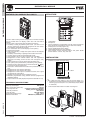
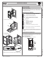
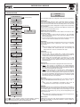
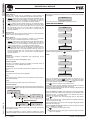
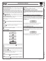
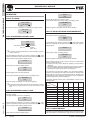
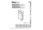
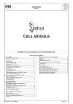
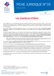
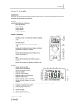
SECTION 3B
CALL MODULE
Download from www.urmet.com Technical Manuals area.
SECTION CONTENTS
sinthesi CALL MODULE Ref.1083/13
2
Technical specifications................................................................2
struCTURE.....................................................................................2
INSTALLATION..................................................................................2
Audio adjusting..............................................................................3
Description of terminals.................................................................3
Camera module connection..........................................................3
Product list....................................................................................4
PROGRAMMING...............................................................................4
Default configuraion......................................................................4
PROGRAMMING WITH KEYBOARD.................................................4
Programming masting...................................................................4
ProgrammING via bluetooth..................................................7
OPERATION......................................................................................8
Calls to users.................................................................................8
Call to switchboard........................................................................9
Communication and door opening................................................9
Transmission of special codes......................................................9
Entry of door-opener codes..........................................................9
“Postman” function.......................................................................9
EXAMPLES OF MODULAR CONSTRUCTIONS..............................10
2 VOICE - Technical Manual
sec.3b −−−− Ref. 1083/13
SINTHESI CALL MODULE
STRUCTURE - INSTALLATION
sinthesi CALL MODULE Ref.1083/13
struCTURE
SINTHESI CALL MODULE
2
1
3
4
5
1
2
3
4
5
6
7
8
9
X
0
6
7
The Ref. 1083/13 calling module corresponds to 2 Sinthesi modules
and is provided with LCD display, built-in door unit and back-lit
buttons.
The Ref. 1083/13 call module offers the following functions:
• Possibility of calling all potential system users (128 users for 32
risers) by entering the physical code (2 digits for the riser number
and 3 digits for the apartment number).
• Two 16-character row LCD with display of user repertory.
• Alphanumeric keypad
• 4200-name repertory; a 4-digit door-opener code can be assigned
to each name.
• Possibility of associating 4-digit logical call codes to the names.
• 100 door-opener codes not associated with names.
• Name selection using arrow keys and search by initial letter.
• Management of main entrance electric lock with capacitance
discharge and holding current and also with changeover relay
output.
• Output contact for control of vehicle entrance electric lock.
• Door-opener pulse (unrestricted or protected by privacy feature).
• Postman function: direct opening of main entrance with
key
on days and at times programmed.
• Direct call to switchboard if two buttons are pressed at the same
time.
• Management of main entrance Hall button.
• Management of main entrance door sensor.
• Management of video input for surveillance camera and T signal
management for video switch.
• Speaker and microphone volume adjustment trimmer.
• Bluetooth programmable using portable devices equipped with
dedicated software
• Output of device for deaf people (European law SOCU0611477A)
TECHNICAL SPECIFICATIONS
CALL MOSULE
Power voltage (LINE): Stand-by consumption: Max. consumption (Video call)
Lock output SE+ SE-: Lock relay C/NC/NO: Lock relay SE2:
Working temperature range: Reference standards: 36 – 48Vdc
Max 85 mA
220 mA
capacitance discharge 22-24Vdc
holding current max 200mAdc
Max 24V 5A
Max 24V 300mA
- 10°C + 50°C
EN61000-6-3, EN61000-6-1
1. Loudspeaker
2. Microphone
3. Volume adjustment of loudspeaker and call module microphone
(they can also be accessed from the rear side of the module)
4. Infrared port for remote programming
5. Graphic backlit alphanumeric display
6. Yellow backlit buttons for name selection
7. Green backlit numeric keyboard buttons, with yellow backlit
function buttons: ‘Cancel’, ‘Key’ and ‘Call’
INSTALLATION
1. Install the module at the height shown.
1
2
3
4
5
6
7
8
9
X
0
h = 1,55 ÷ 1,60 m
§ Tosuggested
obtain the best reading of the call module display, it is
not to keep it against the light and not to directly point
it to strong light sources (for ex. sun, street lamps, lamps, flashes
or reflections).
2. Fit the module holder frame in the flush-mounting box.
A
4 mm
−−−− sec.3b
2 VOICE - Technical Manual
Ref. 1083/13
SINTHESI CALL MODULE
INSTALLATION
The audio levels are trimmed in factory, so they don’t need to be
changed in most installations.
If they must be changed, use a screwdriver on the suitable adjustments
(3), accessible from the module front side (by removing the upper
front) and from the rear side.
DESCRIPTION OF TERMINALS
V5
V3
NO
NC
C
SE+
SE+
-
4. Tip the frame and connect wires.
] LINE
}
B
A
REF
] ILA
Activation main entrance electric lock
Positive for pedestrian electric lock activation
Negative for pedestrian electric lock activation
} Do not use
Bus line in
TT+
CT
PA
SP
] SE2
Reference for control camera signal / video switch
Control camera signal / video switch
SINTHESI CALL MODULE
Audio Adjusting
3. Fit the modules in the frame.
Reference for video switch
Command for video switch
Reference for PA and SP
Hall button
Open door detector (*)
Driveway electric lock activation (NO contact)
}
RS485 serial port connection (for future developments)
Output of device for deaf people
J2
2
GT T3
G T4
G
0~ 2~
1
(*) the terminal pin SP is connected by default to the terminal pin CT;
to connect the normally closed door sensor (with closed door), remove
the jumper.
CAMERA MODULE CONNECTION
In order to obtain a video door phone call station, a camera module
can be installed with the digital call module. To connect the camera
module Ref. 1745/40 (colour), use the connector on the rear side of
the call module for the provided cable:
RED - Power positive (+TC)
BLACK - Power negative (R1)
WHITE - Video signal coax (Shield V5 + Core V3)
5. Close the frame.
6. Fit the panel on the frame.
A
B
Ref.
1083/13
A
B
B
A
Ref.
1745/40
CALL MODULE
A
§
An anti-theft screw is provided to increase installation security.
2 VOICE - Technical Manual
sec.3b −−−− Ref. 1083/13
SINTHESI CALL MODULE
PROGRAMMING - PROGRAMMING WITH KEYBOARD
SINTHESI CALL MODULE
PRODUCT LIST
PROGRAMMING
To install the call module, Sinthesi products and accessories can be
used.
The following list contains the main codes which can be used.
Embedding box
For 2 modules For 3 modules For 4 modules Ref. 1145/52
Ref. 1145/53
Ref. 1145/54
The call module with directory can be programmed as follows:
• Locally, with the keypad, without opening the module frame.
• With a BlueTooth device (PDA, Telephone, etc.) equipped
with Windows Mobile 6.1 and a suitable software which can be
downloaded from the reserved area of the website www.urmet.
com.
• With a PC provided with BlueTooth interface, equipped with a
suitable software which can be downloaded from the reserved area
of the website www.urmet.com.
Frames and module holders
For 2 modules For 3 modules For 4 modules Ref. 1145/62
Ref. 1145/63
Ref. 1145/64
Wall cover frame
For 2 modules For 3 modules Per 4 moduli For 4 modules (2 frames for 2 modules) Ref. 1145/712
Ref. 1145/713
Ref. 1145/714
Ref. 1145/724
Rain hood
For 2 modules For 3 modules For 4 modules For 4 modules (2 frames for 2 modules) Ref. 1145/612
Ref. 1145/613
Ref. 1145/614
Ref. 1145/624
Case and hood
For 2 modules For 3 modules For 4 modules For 4 modules (2 frames for 2 modules) Ref. 1145/312
Ref. 1145/313
Ref. 1145/314
Ref. 1145/324
DEFAULT CONFIGURATION
Language: Module type: Module ID: Code type: Device type: Guaranteed conversation time: Interruption: Main entrance lock time: Type of main entrance door-opener: Vehicle entrance door-opener time: Type of vehicle entrance door opener: Password: Number of surveillance cameras: Key click: Postman function: Italian
main
0
physical code
video
30s
not enabled
1s
private
1s
private
1000
0
yes
no
§ Tothe restore
the default values, power the device holding down
X, 8 and 6 keys.
programmING WITH KEYBOARD
Case and hood for semi-flushed gate installation
For 2 modules Ref. 1145/342
Postalbox
For 2 modules Ref. 1145/42
programmING MASTING
To access the configuration and programming menu must:
• enter the 99999;
• the display shows:
PASSWORD
Blank module and repertory
Repertory module Blank module Ref. 1145/50
Ref. 1145/59
All Sinthesi products, characteristics and installation procedures are
shown in “Technical product manual - door phone and video door
phone systems” in the “Sinthesi panels” section.
__
• Enter the password (default 1000) and press
following programming menu:
to access the
LANGUAGE
CONFIGURATION
NAMES
DOOR
LINGUA
OPENER
CALL MOSULE
Use the arrow keys to scroll the programming menu. Press
to access
the selected second level menu; press X to quit programming.
LANGUAGE
In the “language” menu, select the operating language with the
buttons
and confirm with
.
−−−− sec.3b
2 VOICE - Technical Manual
Ref. 1083/13
SINTHESI CALL MODULE
CONFIGURATION
CONFIGURATION
ALLOWED
Exit programming
Module type
The calling module may be a main or secondary device. All systems
users can be called from the main device; only users of the related
riser column can be called from the secondary device. The user who
receives the call is able to distinguish the origin of the call according
to ring duration.
There may be 2 secondary call stations with different numbers in the
same riser column (secondary 0 or 1).
MODULE TYPE
<P RI>
<SEC>
MODULE ID
Only if secondary
00
CODE TYPE
<PHYS>
<LOGIC>
SECONDARY
< 0>
<1>
DEVICE TYPE
<AUDIO>
<V I D E O >
BUSY TIME
30
STOPABLE
< YES> <N O >
DOOR LOCK T1
01
DOOR OPENER 1
<FREE>
<SECRET>
DOOR LOCK T2
01
DOOR OPENER 2
<FREE>
<SECRET>
PASSWORD
1000
CONTROL CAMERAS
<0> < 1 > < 2 > < 3 > < 4 >
LCD CONTRAST
<+>
<->
BUTTON SOUND
< YES> < N O >
DAY
<MONDAY>
TIME
12:30
POSTMAN FUNCTION
< YES> < N O >
Press
to confirm selection; press X, to cancel selection. Pressing
X for 3s, returns to the start of the menu; to quit, press X again.
If the value entered is not correct, the display shows:
2 VOICE - Technical Manual
The parameters which are configured in this menu are the following:
Module ID: door unit number
Set a number from 00 to 03 for a main module or from 00 to 31 for a
secondary module.
• Two main stations cannot have the same ID. Two secondary
stations may have the same ID but must have a different number
(see next parameter).
• The ID of the secondary door unit must be the same as the riser
column ID set in the Ref. 1083/50 riser column interface.
Secondary
In the case of a secondary module and if there is only one secondary
in the riser column, set 0; if there are 2, set 0 and 1 in the two
secondaries.
§ The
secondary call station with ID=0 must be connected to the
column interface Ref. 1083/50 IN0 input, the secondary call
station with ID=1 must be connected to IN1 input.
Code type
Type of user call code.
• Physical code: users are called with a 5-digit code as follows:
ccnnn, where cc indicates the riser column (from 00 a 31) and nnn
indicates the number of the apartment (from 000 a 127)
• Logical code: users are called with a a number of 1 to 4 digits
from 1 to 9999. To use the logical codes, the names must be
programmed, assigning the logical call code to the physical code
of the apartment.
Device type
Indicates whether the module is equipped with local camera unit.
• Video: a local camera is connected to the “VIDEO MODULE”
connector; the call station is a video door phone. Up to 4 surveillance
cameras, which can be displayed by users using the auto power-on
key, can be connected to the V3/V5 input.
• Audio: no local camera unit is connected to the “VIDEO MODULE”
connector; the call station is a door phone. Up to 4 surveillance
cameras, which can be displayed by users using the auto power-on
key, can be connected to the V3/V5 input. In the case of a single
surveillance camera, the call station becomes a video door phone
and uses this camera in the call phase.
Busy time
This is the guaranteed communication time. The values (in seconds),
which can be selected with the arrow keys, are 01, 10, 20, ….70.
§ The
busy time (guaranteed conversation time) must
programmed in the same way for all system call station.
be
Stopable
During auto power-on or an intercommunicating call or consultation of
the video door phone answering service, the riser column concerned
or the entire system is in Busy status which, according to how this
parameter is programmed, may or may not be interrupted by a call
from the door unit.
§ The
parameter “Stopable” (interruption) must be programmed in
the same way for all system call station.
Door lock T1
Maintenance time of the main entrance electric lock (terminals SE+/
SE-) and of activation of terminals C/NC/NO. Enter a number (in
seconds) from 1 to 90.
sec.3b −−−− CALL MODULE
CONFIGURATION
SINTHESI CALL MODULE
CODE NOT
The configuration menu is as follows:
Ref. 1083/13
SINTHESI CALL MODULE
SINTHESI CALL MODULE
CONFIGURATION
Door opener 1
Electric lock control may be “protected by privacy feature” or
“unrestricted”. The door unit behaves as follows in the two cases:
• ‘Secret’: pressing the door-opener button of an apartment station,
the electric lock of the call station is released only if a call has
been received or a voice conversation is in progress with this or if,
following auto power-on, it is in video connection with this.
• ‘Free’: pressing the door-opener button of an apartment station,
the electric lock of the door unit is released only if this has been
configured as main, or the user belongs to the riser column of the
same secondary door unit. This riser column is defined by the
ID of the secondary door unit. This function is normally used on
secondary stations.
ERROR ID
In this case, return to configuration and correct the error.
NAME PROGRAMMING
The name programming menu is as follows:
ENTER
Door lock T2
Activation time of the vehicle entrance electric lock (SE2 terminals).
Enter a number (in seconds) from 1 to 90.
Door opener 2
The electric lock may be controlled in “private” or “unrestricted”
mode. The door unit behaves as follows in the two cases:
• ‘Secret’: pressing the door-opener button of an apartment station,
the electric lock of the call station is released only if a call has
been received or a voice conversation is in progress with this or if,
following auto power-on, it is in video connection with this.
• ‘Free’: pressing the door-opener button of an apartment station,
the electric lock of the door unit is released only if the door unit
is configured as main, or the user belongs to the riser column of
the same secondary door unit. This riser column is defined by the
ID of the secondary door unit. This function is normally used on
secondary stations.
Password
Password for accessing configuration and programming of call
module data.
Set a value from 1000 to 9999 (default 1000).
Control cameras
Number of surveillance cameras connected to terminals V3/V5 (if
more than one, via the 1083/69 video switch).
LCD contrast
Press the UP key to increase contrast and the DOWN key to reduce
this.
Button sound
The button sound function can be disabled.
Time
Enter the time to be programmed on the internal clock.
Postman function
If the function is enabled, the main entrance can be opened simply by
pressing the
key on the days and at the time set in the following
screen pages.
POSTMAN FUNCTION
<YES> < N O >
MONDAY
<YES>
<YES> < N O >
FROM
00:00
TO
00:00
...
SUNDAY
<YES> < N O >
FROM
00:00
TO
00:00
The function can be enabled for each day of the week, also defining
the related time band.
On exiting configuration, a check is made on whether the system
already comprises a device of the same type with the same ID and, if
−−−− sec.3b
MODIFY
DELETE
DELETE
LINGUA
ALL
The name programming menu can be scrolled using the arrow keys;
press X to quit programming or
to access the menu item.
Enter
NAME:
PHYSICAL CODE:
LOGICAL CODE:
DOOR OPENER
LINGUA CODE:
Day
With the arrow keys, select the day of the week to be programmed in
the internal calendar.
CALL MOSULE
secondary, with the same number (0 or 1). If so, the following message
is displayed:
Up to 32 characters can be entered using the keypad as for a
telephone; to insert a space (
), press the 1 key once only; press
the 0 key once to move to the second line (
). Press the arrow keys
to scroll all available characters for the language used.
Press
to move to insertion of the physical code.
Press X to cancel the last character. Pressing X without inserting
characters returns to the name programming menu.
If the name entered already exists, an error message is displayed and
the data must be re-entered.
Enter the physical call code of the apartment in the format XYABC,
where XY is the riser column (00-31) and ABC is the address of the
apartment (0-127). In systems without Ref. 1083/50 riser column
interface, the riser column code is 00.
Press
to move to the next step (logical code or door-opener
code).
Press X to cancel the code. Pressing X without inserting characters
returns to the previous step.
If the code entered is not valid, an error message is displayed and the
data must be re-entered.
Enter the logical call code of the apartment which must be a a number
of 1 to 4 digits from 1 to 9999.
Press
to move to the door-opener code.
§ Ifpage
the device is set with code type = physical codes, this screen
is not displayed.
2 VOICE - Technical Manual
Ref. 1083/13
SINTHESI CALL MODULE
PROGRAMMING VIA BLUETOOTH
After this step, the name is inserted in the repertory and a new name
can be inserted.
Modify
From this menu, the repertory can be scrolled using the arrow keys;
press
to modify the data following the same screen pages as for
insertion.
Delete
From this menu, the repertory can be scrolled using the arrow keys;
pressing
, confirmation of deletion is requested.
Delete all
From this menu, the entire names repertory can be deleted; pressing
, confirmation of deletion is requested.
DOOR-OPENER
This menu is used to manage door-opener codes not associated with
names in the repertory. The menu as follows:
ENTER
Delete all
From this menu, all the door-opener codes can be deleted; pressing
, confirmation of deletion is requested
PROGRAMMING VIA BLUETOOTH
The call module is equipped with a Bluetooth receiver-transmitter
to facilitate programming of configuration, names and door-opener
codes.
Programming with PDA or telephones
Access the programming mode by entering the code 99999 followed
by the password (default 1000), activate the 2Voice_Mobile software
(which can be downloaded from the site www.urmet.com) previously
installed on the PDA or on the telephone and, from the telephone,
make the connection between the software of the telephone and the
call module.
The display shows:
SINTHESI CALL MODULE
Press X to cancel the code. Pressing X without inserting characters
returns to the previous step.
If the code entered is not valid, an error message is displayed and the
data must be re-entered.
The logical code must be univocal in the repertory programmed.
If a door-opener code to be assigned to the user inserted, enter the
door-opener code which must be a 4-digit number from 0001 to 4999.
This code will open the main entrance; to open the vehicle entrance,
enter a door-opener code from 5000 to 9999. After insertion, press
.
If a door-opener code is not to be assigned to the user inserted,
press
without code.
Press X to cancel the code. Pressing X without inserting characters
returns to the previous step.
If the code entered is not valid or already exists, an error message is
displayed and the data must be re-entered.
BLUETOOTH
CONNECTED
Set as indicated in the user manual of the 2Voice_PC software.
To exit Bluetooth programming, press X for 2 seconds.
Programming with PC
Access the programming mode by entering the code 99999 followed
by the password (default 1000), activate the 2Voice_PC software
(which can be downloaded from the site www.urmet.com) previously
installed on the PC and make the connection between the software
and the call module.
The display shows:
BLUETOOTH
CONNECTED
Set as indicated in the user manual of the 2Voice_PC software.
To exit Bluetooth programming, press X for 2 seconds.
MODIFY
DELETE
DELETE
LINGUA
ALL
The door-opener codes programming menu can be scrolled using the
arrow keys; press X to quit programming or
to access the menu
item.
CALL MODULE
Enter
Enter the door-opener code which must be a 4-digit number from 0001
to 9999. A code between 1 and 4999 will open the main entrance; a
code between 5000 and 9999 will open the vehicle entrance. After
insertion, press
.
Press X to cancel the code. Pressing X without inserting characters
returns to the previous step.
If the code entered is not valid or already exists, an error message is
displayed and the data must be re-entered.
Modify
From this menu, the list of the door-opener codes can be scrolled with
the arrow keys; press
to modify the code selected.
Delete
From this menu, the list of the door-opener codes can be scrolled with
the arrow keys; pressing
, confirmation of deletion is requested.
2 VOICE - Technical Manual
sec.3b −−−− Ref. 1083/13
SINTHESI CALL MODULE
OPERATION
OPERATION
WRONG
SINTHESI CALL MODULE
CODE
CALLS TO USERS
and the display returns to stand-by status;
If the code is valid but the system is busy, the display shows:
In stand-by mode, the call module displays:
SELECT NAME
LINE BUSY
AND PRESS
WAIT
If no names have been inserted in the repertory, the display shows
TYPE CODE
When the system is free again, the call can be repeated.
CALL BY SELECTING NAME FROM REPERTORY
PRESS
CALL BY ENTERING PHYSICAL CODE
Press the arrow keys to scroll the list of names in alphabetical order.
The names are shown on the display:
ROSSI
If the call module is configured with physical codes, enter the 5-digit
code as follows:
CODE:
01003
riser column number
(00 ÷ 31)
apartment
number
(000 ÷ 127)
§ Incolumn
systems without Ref.1083/50 riser column interface, the riser
code is 00.
Use X to delete the character if you make a mistake; with
, if the
system is free and the code is valid, the call is made and for the entire
pick-up wait time (max. 60s) the display shows:
CALLING
If the code is not valid, the display shows:
WRONG
CODE
and the display returns to stand-by status;
If the code is valid but the system is busy, the display shows:
LINE BUSY
WAIT
When the system is free again, the call can be repeated
§ Athephysical
code that starts with zeroes can be entered, omitting
zeroes (e.g. physical code 1001 will call riser column 01 user
001).
Pressing X, stand-by status is restored; with
, if the system is free,
the call is made and for the entire pick-up wait time (max. 60s) the
display shows:
CALLING
If the system is busy, the display shows:
LINE BUSY
WAIT
When the system is free again, the call can be repeated.
If the repertory contains a high number of names, to make a faster
search, proceed as follows.
• Press an arrow key once to display the repertory. The first name is
displayed;
• Use the keypad to select the initial letter of the name to be found;
the first name that starts with the letter indicated is displayed;
• Use the arrow keys to search for the name required.
For example, to find the name “ROSSI”, from the previous display,
press the 7 key three times to position the repertory on the first name
starting with “R”; if there are no names starting with “R”, the first name
in alphabetical order is displayed. Use the arrow keys to navigate the
repertory starting from the name displayed.
Association between buttons and numbers/letters is shown in the
following table:
press
1
2
space
1
3
4
2
A
B
C
2
CALL by ENTERING LOGICAL CODE
3
D
E
F
3
If the call module is configured with logical codes, enter a code of
maximum 4 digits.
The digits entered are shown on the display:
4
G
H
I
4
5
1002
Use X to delete the character if you make a mistake; with
, if the
system is free and the code is valid, the call is made and for the entire
pick-up wait time (max. 60s) the display shows:
CALLING
If the code is not valid, the display shows:
−−−− sec.3b
5
button
1
CODE:
CALL MOSULE
MARIO
5
J
K
L
6
M
N
O
6
7
P
Q
R
S
8
T
U
V
8
9
W
X
Y
Z
0
0
7
9
CALL TO SWITCHBOARD
If the system includes a concierge switchboard set to “day”
functioning, this will intercept and manage all the calls made from the
main call modules. The switchboard in “day” status can also be called
2 VOICE - Technical Manual
Ref. 1083/13
SINTHESI CALL MODULE
OPERATION
CALLING
If the code is valid but the system is busy, the display shows:
LINE BUSY
WAIT
When the system is free again, the call can be repeated.
ENTRY OF DOOR-OPENER CODES
If door-opener codes (unrestricted or associated with names in the
repertory) have been programmed on the call module, the door
(pedestrian or vehicle) can be opened entering this code. The main
entrance lock is activated for codes from 0001 to 4999; the vehicle
entrance lock is activated for codes from 5000 to 5999.
When the call module is on stand-by, pressing the key
, the
display shows
DOOR LOCK
RELEASE CODE:
Enter the 4-digit door-opener code programmed. The display shows
this code with *:
DOOR LOCK
COMMUNICATION AND DOOR OPENING
If a call is made, when the user lifts the hand-set, the module
establishes a conversation and for the entire communication time
(max. 10 minutes) the display shows:
SPEAK
PLEASE
If the user presses the button to open the main or vehicle entrance,
the module activates the corresponding output with temporary display
of:
COME IN
PLEASE
RELEASE CODE: ****
SINTHESI CALL MODULE
directly with the key
without any selection, or pressing several
buttons at the same time.
If the system is free, the call is made and for the entire pick-up wait
time (max. 60s) the display shows
Press X to delete the data if you make a mistake; after entry, press
.
The display returns to stand-by status.
If the code is amongst those programmed, the lock is activated and
the display shows:
COME IN
PLEASE
If the code is not amongst those programmed, the lock is not activated
and the display shows:
WRONG
CODE
When the user called hangs up, the communication is closed and the
module returns to stand-by status.
If the call is intercepted by the switchboard and this puts the call
module on hold in order to call an apartment station, the display
shows:
WAIT
PLEASE
“POSTMAN” FUNCTION
If time bands have been programmed on the call module and the
function is active, the main entrance can be opened on the days and
at the times established simply by pressing the
key.
After pressing this key, any door-opener code can be entered to open
the vehicle entrance.
When communication between the module and the switchboard
or directly with the apartment station called by the switchboard is
restored, the display shows:
SPEAK
PLEASE
TRANSMISSION OF SPECIAL CODES
If the system comprises special decoders, the call module can send
commands to activate load driving outputs (lights, gates, etc.)
When the call module is on stand-by, pressing the 0 key, the display
shows
CODE:
0_
Continuing to press the 0 key for 2s, the call module switches to
special code mode and the display shows:
SPECIAL CODE:
0_
CALL MODULE
Enter the 3-digit code (from 1 to 255) programmed in the special
decoder to be activated. The display shows this code with *:
SPECIAL CODE:
0***
Press X to delete the data entered; on completion of data entry, press
to sent the code. The display returns to stand-by status.
2 VOICE - Technical Manual
sec.3b −−−− Ref. 1083/13
SINTHESI CALL MODULE
EXAMPLES OF MODULAR CONSTRUCTIONS
SINTHESI CALL MODULE
EXAMPLES OF MODULAR CONSTRUCTIONS
1
2
3
4
5
6
7
8
9
X
0
Ref.
Description
N°
1083/13
Call module
1
1145/52
Flush mounting box
1
1145/62
Module holders and frames
1
1145/712
Embedding frame (°)
1
1145/612
Rain hood (°)
1
1145/312
Hooded housing
1
Flush mounting
Wall mounting
(°) optional, alternatives
1
2
3
4
5
6
7
8
9
X
0
Ref.
Description
N°
1083/13
Call module
1
1745/40
Colour camera module
1
1145/50
Repertory module
1
1145/54
Flush mounting box
1
1145/64
Module holders and frames
1
1145/714
Embedding frame (°)
1
1145/614
Rain hood (°)
1
1145/314
Hooded housing
1
Flush mounting
Wall mounting
(°) optional, alternatives
1
2
3
4
5
6
7
8
9
X
0
Ref.
Description
N°
1083/13
Call module
1
1145/50
Repertory module
1
1145/53
Flush mounting box
1
1145/63
Module holders and frames
1
1145/713
Embedding frame (°)
1
1145/613
Rain hood (°)
1
1145/313
Hooded housing
1
Flush mounting
Wall mounting
(°) optional, alternatives
1
2
3
4
5
6
7
8
9
X
0
Ref.
Description
N°
1083/13
Call module
1
1745/40
Colour camera module
1
1145/50
Repertory module
1
1145/52
Flush mounting box
2
1145/62
Module holders and frames
2
1145/724
Embedding frame (°)
1
1145/624
Rain hood (°)
1
1145/324
Hooded housing
1
Flush mounting
Wall mounting
CALL MOSULE
(°) optional, alternatives
1
2
3
4
5
6
7
8
9
X
0
Ref.
Description
N°
1083/13
Call module
1
1745/40
Colour camera module
1
1145/53
Flush mounting box
1
1145/63
Module holders and frames
1
1145/713
Embedding frame (°)
1
1145/613
Rain hood (°)
1
1145/313
Hooded housing
1
Flush mounting
Wall mounting
(°) optional, alternatives
10 −−−− sec.3b
2 VOICE - Technical Manual