1
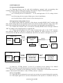
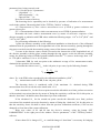
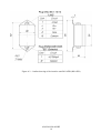
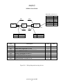
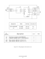
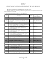
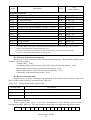
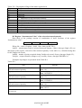
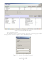
Scientific Production Company “Doza” DETECTING DEVICES UDKG-100 User Manual AJAH.418268.029RE Cont ent 1 Description and operation of the product ………………………………….. 1.1 Product functionality ……………………………………..………… 1.2 Technical characteristics ………………………………………...…. 1.3 Configuration …………………………………………...……..…… 1.4 Design and operation …………....……………………………...…... 1.5 Marking and sealing …………………...…………………………… 1.6 Packing ……………………………………………………………... 2 Intended use ………………………………………………………..……… 2.1 Operational limitations ……………………………………………… 2.2 Preparation of the product for use ..……………………….………… 2.3 Use of a product …….….….……………………………..…………. 2.4 Adjustment ………………………………………………..………… 3 Maintenance ……………………………………………………..………… 3.1 General notes ……………………………………………...……...… 3.2 Safety precautions ……………………………………………..…… 3.3 Maintenance routine ………………………………………………... 4 Calibration routine ………………………….…………………………...… 4.1 General requirements ...…………………………………………..… 4.2 Preliminary arrangements …………………………….…………..... 4.3 Safety precautions ………………………………………………..… 4.4 Conditions …….……….………….………….………….……….… 4.5 Procedure ………………………….……………………………...… 5 Routine repairs …………………………………………………………...... 6 Storage ………………………………………………………………...…... 7 Transportation ……………………………………………………………... 8 Disposal …………………………………………………………………..... 3 3 3 5 5 7 7 8 8 8 9 9 10 10 10 10 10 10 11 11 11 11 13 13 13 14 Appendix A Outline drawing ………………………...…..……..……..………… Appendix B Wiring diagram ……………………...……………………………... Appendix C Assignment of the connector contacts ………...……......……...…... Appendix D Description of data exchange registers using the DiBUS protocol ………………………………………………….……. Appendix E Software“TETRA_Checker” User Manual ……………….………. Appendix F Measurement of the specific activity of liquids by immersion of the detector assembly into the pool (reservoir) ……...…………………….…. 15 17 19 AJAH.418268.029RE 2 20 23 28 This User Manual contains information on design, principle of operation, characteristics of the product and instructions essential for correct and safe use of this product (intended use, maintenance, servicing, storage and transportation), as well as information regarding the utilization of the product. 1 DESCRIPTION AND OPERATION OF THE PRODUCT 1.1 Product functionality Detecting devices UDKG-100 AJAH.418268.029 (hereinafter – detecting devices) are intended for measurement of gamma quanta fluence or the exposure dose rate (hereinafter EDR) in the boreholes, pulp and other liquid media, including logging works. Detecting devices are used at the industrial facilities: enterprises for radioactive waste conditioning and management, in the areas neighbouring to the nuclear and nuclear-hazardous (including nuclear reactors), as a part of systems, complexes and installations for radiation monitoring. Detecting devices are able to convert measurement information into data with content and formatting complying with the DiBUS data exchange protocol and to transfer the data to external information channels via communication lines with RS-422 or RS-485 interface. Table 1.1 describes modifications of detecting devices that differ by interface units and interface types. Table 1.1 – Modifications of detecting devices Designation AJAH.418268.029-01 AJAH.418268.027 AJAH.418292.008 AJAH.418268.029-02 AJAH.418268.027 AJAH.418292.008-01 Description Detecting device UDKG-100DD including: Detector assembly BDKG-100-07 Interface unit BS-16DD Detecting device UDKG-100PD including: Detector assembly BDKG-100-07 Interface unit BS-16PD Interface type RS-422 RS-485 1.2 Technical characteristics 1.2.1 Energy range ……………….…….…..……….…..……….…..….. not less than 0.1 MeV. 1.2.2 Measurement range of the gamma photon flux ……….....…..….... 40 to 2·105 photons·s-1. 1.2.3 Measurement and indication ranges of the EDR of gamma radiation: - indication range …..……………..…….…………..……………………… 1 to 5·104 R·h-1; - measurement range ……………...…….……….…...…………………… 10 to 5·104 R·h-1. 1.2.4 Limits of the permissible basic relative conversion error of EDR of gamma radiation and gamma photon flux …….…………….…………………………………………... not more than ±30 %. 1.2.5 Sensitivity to gamma radiation of 137Cs (662 keV): - EDR of gamma radiation ………..…………….……..………...………. 1.9 s-1 per 1 R·h-1; - gamma photon flux .…………………………..…………..……...…. 0.5 s-1 per 1 photon·s-1. 1.2.6 Warm-up time ….………………………...….…………………..….. not more than 1 min. 1.2.7 Continuous operation without limitation of number of turning on/off ... not less than 24 h. 1.2.8 Instability during 24 hours of continuous operation .………...……… not more than ±5 %. 1.2.9 Detecting devices provide generation of self-diagnostics codes and current measurement information for the external information channel and access to the processed information using DiBUS protocol, via communication line based on the RS-485 or RS-422 interface. 12 1.2.10 Power supply DC voltage .……………………………...………..…………... + 24 12 V. 1.2.11 Current consumption at voltage 24 V ………………………..….. not more than 20 mA. AJAH.418268.029RE 3 1.2.12 Detecting device’s ambient air operation conditions: - operating temperature range …………………………………………… minus 40 to +50 °C; - relative humidity …………..…………….………………………..…… up to 98 % at 35 °C; - atmospheric pressure ………………………………………………….… 66.0 to 106.7 kPa; - content of the corrosive agents in the ambient air corresponds to the values in Table 1.2. Table 1.2 Type of atmosphere Designation Description I Relatively clean II Industrial III Maritime Content of the corrosive agents Sulfur dioxide gas not more than 20 mg/(m2·day) (not more than 0.025 mg/m3); Chlorides not more than 0.3 mg/(m2·day) Sulfur dioxide gas not more than 20 to 250 mg/(m2 ·day) (not more than 0.025 to 0.31 mg/m3); Chlorides not more than 0.3 mg/(m2·day) Sulfur dioxide gas not more than 20 mg/(m2·day) (not more than 0.025 mg/m3); Chlorides – 30 to 300 mg/(m2·day). 1.2.13 Limits of the complementary measurement error of EDR of gamma radiation under operation conditions: - with ambient air temperature deviation from normal conditions 10 C ...................... ±10 %; - under increased relative humidity up to 98% at +35 C ……………………....…….. ±10 %. 1.2.14 Detecting devices withstand submersion of the device assembly into water: - to the depth …………………………………………………………………. down to 100 m; - for a period of time ………………………………...……….……………. not less than 24 h. 1.2.15 Detecting devices withstand sinusoidal vibrations in the frequency range from 10 to 55 Hz with displacement amplitude 0.35 mm. Limits of the complementary measurement error of EDR of gamma radiation under sinusoidal vibrations …………...…………………………..…………………………………….………….. ±10 %. 1.2.16 Detecting devices are stable against seismic impacts with magnitude 7 according to the MSK-64 scale, being installed on the building structures of the industrial site at 70 to 30 m relative to the grade level. After the seismic impact with the above mentioned parameters detecting devices are operable within the limits stated in sections 1.2.4, 1.2.9, during the whole life cycle under specified operation conditions. 1.2.17 Degree of protection provided by casings of the detecting devices’ elements: - detecting device assembly BDKG-100-07 …………….…..…………....……..……… IP68; - interface units BS-16DD, BS-16PD ……….……………….……………..…...…..….. IP65. 1.2.18 Detecting devices are stable against electromagnetic interference of 2 grade according to the IEC 1000-4-8-93, IEC 1000-4-9-93, IEC 61000-4-2-95, IEC 61000-4-3:2006, IEC 61000-4-4:2004, IEC 61000-4-5-95, IEC 61000-4-6-96, IEC 61000-4-12-95 and comply with the emission standards stated by the CISPR 22:2006 for equipment of class A. 1.2.19 Detecting devices are stable against short (duration 5 minutes) overloads of the monitored radiation with AEDR of gamma radiation 5·105 R·h-1. After overload the detecting devices are operable, basic relative error of measurement remains within limits. 1.2.20 By its protection against electric shock detecting devices comply with the IEC 61010-1:2001. 1.2.21 Detecting devices are fire-safe products; fire probability is less than 10-6 year-1. AJAH.418268.029RE 4 1.2.22 Detecting devices withstand the exposure to decontaminating solutions: 1) boric acid (H3BO3) – 16 g, sodium thiosulfate (Na2S2O3·5H2O) – 10 g, distilled water – up to 1 liter; 2) trisodium phosphate or sodium hexametaphosphate (any detergent) – 10 - 20 g/l water solution; 3) 5 % citric acid solution in rectified alcohol – for connectors and contacts. 1.2.23 Overall dimensions and weights do not exceed values shown in the Table 1.3. Table 1.3 - Overall dimensions and weight of the detecting devices’ elements Designation AJAH.418268.027 AJAH.418292.008 AJAH.418292.008-01 Name of the element (unit) Detector assembly BDKG-100-07 (without logging cable at the cable entry) Interface unit BS-16DD Interface unit BS-16PD Overall dimensions, mm Weight, kg Ø38530 3.0 1768064 1768064 0.7 0.7 1.2.24 The length of the logging cable (type KG2x50 KSh) between the detector assembly BDKG-100-07 and the interface unit BS-16 ..……...……...……….... not more than 1000 m. Weight of 10 meters of type KG2x50 KSh cable ……..……..…….....….. not more than 2.5 kg. 1.2.25 Mean time before failure ……………………………..….……. not less than 5000 hours. 1.2.26 Mean life time …………………………………………….…...…. not less than 10 years. 1.2.27 Detecting devices do not contain precious materials. 1.3 Configuration 1.3.1 Detecting device consists of detector assembly BDKG-100-07 AJAH.418268.027 and interface unit BS-16DD AJAH.418292.008 (or BS-16PD AJAH.418292.008-01), connected with each other by the logging coaxial cable. The detector assembly BDKG-100-07 includes detector module AJAH.418285.041 and cable entry AJAH.687111.001 with logging cable. 1.3.2 Detecting device comes with installation kit and spare parts and accessories kit. Interface PI-02 and software “TETRA_Checker” are included in the delivery kit by the customer’s request. 1.4 Design and operation 1.4.1 The detecting device’s operating principle is based on conversion of the ionizing radiation energy into series of conditioned electric pulses with count rate (frequency) proportional to the gamma photon flux or exposure dose rate. 1.4.2 The detector assembly BDKG-100-07 consists of two parts: - detector module with internal connector of SRG-50-11FV type, which is closed by the plug AJAH.715131.001 during transportation; the connector is intended for connection of the cable entry; - cable entry with connector of SRG-50-58PV type for connection to the detector module; during transportation it is closed by the plug AJAH.713721.001; - sealing ring providing air tightness of screw connection between the cable entry and the detector module. Overall and fitting dimensions of elements are presented in the Appendix A. 1.4.3 The detector module has a cylindrical casing made of stainless steel 12H18N9T, supplied with load bearing ring on one side and detachable threaded joint – on another. AJAH.418268.029RE 5 1.4.4 The cable entry casing is connected to the threaded joint; the casing is made of stainless steel, in its termination point the coaxial load bearing cable is dressed. The termination point is supplied with a ring for attachment of the load bearing rope. The wiring diagram is presented in the Appendix B, for the assignment of the connector contacts see Appendix C. 1.4.5 Detecting device is comprised of: - single-crystal scintillator NaI (Tl) with dimensions Ø1830; - PMT (photomultiplier tube) FEU-67B; - high voltage converter – for high voltage supply to the FEU-67B; - amplifier-discriminator for amplifying and selection of pulses by amplitude; - pulse conditioner for transfer of electric pulses via a long line. 1.4.6 Power supply of the detector module is provided through the coaxial cable in accordance with the wiring diagram of the Appendix B. The coaxial cable can be as long as 1000 m. 1.4.7 On the opposite side of the cable the cable socket is soldered, type 2RMD24KPN10G5V1, which is intended for the attachment of cable to the connector of the interface unit BS-16DD (PD). 1.4.8 Instead of cable entry the service cable AJAH.685621.032 is allowed for use when calibrating the detecting device. 1.4.9 Scintillator converts gamma radiation energy into scintillations (flashes of light), and the PMT converts those scintillations into electric signals – pulses, which are statistically distributed in the course of time and have different amplitudes and durations. The amplifier-discriminator performs selection of pulses, their amplification and conditioning for transfer via long line. 1.4.10 The sequence of electric pulses from the detector module is transferred to the interface unit through the coaxial cable, where it is transformed into data with content and formatting corresponding to the DiBUS protocol. The signal parameters correspond to the RS-485 or RS-422 interface standard. Assignment of the connector contacts and parameters of the output signals are presented in the Appendix C. 1.4.11 The interface unit processes and converts measurement information received in a form of statistically distributed and conditioned pulses into information about the EDR of X-ray and gamma radiation. The format of information obtained as a result of such transformation is defined by the DiBUS data exchange protocol that provides possibility of data transfer to the external devices intended for visualization, storage, and alarm signalling. Two connectors are located on the ends of the detecting device casing: “LINE” - the connector of ONC-BS-1-10/14 type for connection via communication line to the data processing unit, and “BD” of 2RMGD type for connection of the detecting device assembly. Power supply line and signal line are galvanically isolated from the side of “LINE” connector. 1.4.12 Processing of the measurement information in the interface unit is carried out by “Sliding” or “Following” algorithm, selected by operator during preparation of the detecting device for operation. 1.4.12.1 The “Sliding” algorithm (moving average method) provides continuous measurement of the count rate. The measurement result is determined as an arithmetic mean of separate readings that corresponds to measurement intervals of user-selected duration, and with the number of readings to be averaged also determined by the user. AJAH.418268.029RE 6 The algorithm includes two parameters: - the number of elementary measurements (interval quantity), which can be set to any value between 1 and 60; - duration of the measurement interval (interval time), which can be set to any value between 1 and 65535 seconds. Measurement interval is a period between two subsequent readings (refreshing a measurement result). The default measurement interval set by the manufacturer is 20 seconds. The product of measurement interval time and a number of such intervals represents the averaging time when measuring count rate. The greater this product is the lesser is the statistical uncertainty of measurement; however the response time to changes of the measured quantity is also greater. 1.4.12.2 Algorithm “Following” allows tracking smooth variations, as well as record jumps of the measured quantity. The “Following” algorithm is characterized by a fast response to the measured quantity jumps which exceed the mean value by more than 3σ where ; N – frequency of pulses (s-1) corresponding to the numerical value of jump-like change. At the constant count rate the averaging time is 200 seconds. 1.4.12.3 Parameters of data processing algorithms are presented in the description of data exchange registers of the DiBUS protocol in Appendix D. The algorithm selection procedure is described in the User Manual that comes with the “Tetra_Checker” software, see Appendix E. 1.5 Marking and sealing 1.5.1 Casings of the detecting device elements have nameplates with the following information: 1) the detector assembly BDKG-100-07: - trademark and name of the manufacturer (supplier); - designation of a device of which the assembly constitutes a part; - reference designation of the assembly; - works number of the assembly according to the manufacturer's system of numeration; - ingress protection provided by casings. 2) interface units BS-16DD (PD): - trademark or name of the manufacturer; - designation of a device of which the unit constitutes a part; - reference designation of the detecting device; - works number of detecting device according to the manufacturer's system of numeration; - pattern approval mark of the measurement instrument; - ingress protection provided by casings; - made in Russia. 1.5.2 Place and method of marking of the detecting device elements comply with the design documentation. 1.5.3 Marking of the detector assembly BDKG-100-07 is engraved; marking of the interface units is located on nameplates, which are affixed to the units. 1.5.4 Detecting devices are sealed in accordance with the design documentation. 1.6 Packing 1.6.1 The detecting device’s package complies with the design documentation and provides protection against ingress of atmospheric precipitations and aerosols, splashes of water, dust, sand, solar ultra-violet radiation and limits the ingress of water vapour and gases. AJAH.418268.029RE 7 2 INTENDED USE 2.1 Operational limitations 2.1.1 Detecting devices can be used with installations equipped with corresponding data exchange interface and providing power supply with required voltage for detecting devices. 2.1.2 The following is not allowed during operation: - use of detecting devices at medium (6 – 35 kV) and high (above 35 kV) voltage electric substation; - use of detecting devices as parts of high power electric installations; - use of mobile phones within 10 meters of the detecting devices. 2.2 Preparation of the product for use 2.2.1 Remove plugs from the connectors of the detector assembly BDKG-100-07 and the cable entry, install sealing rings on the termination point of the detector module, attach the casing of the cable entry to the termination point and tighten the screw joint using wrench included in the installation kit. 2.2.2 Connect the interface unit to the detector assembly BDKG-100-07 through connector “BD” according to the wiring diagram (see Appendix B). 2.2.3 Connect the detecting device to PC using communication cable via the “LINE” interface unit connector (RS-485 or RS-422) as shown in the Appendix B. When necessary, use interface convertors RS-232/RS-485, RS-422 or USB/RS-485, RS-422 in accordance with figures 2.1 or 2.2 UDKG-100 Detector assembly BS-16 RS-422, RS-485 24 V Interface convertor RS-422, RS-485/ RS-232 220 V RS-232 RS-232/ USB PC USB PC UDKG-100 Detector assembly RS-422, RS-485 BS-16 24 V Interface convertor RS-422, RS-485/ RS-232, USB and power supply RS-232/ USB Data processing unit (receiving and processing of information) () 2.2.4 Start the “TETRA_Checker” on the PC as described in the Software User Manual (Appendix E) and make sure that detecting device parameters have being correctly read. The devices’ operability can be checked by presence of indication of measurement result in the window “Measurement information” of the “TETRA_Checker” software. 2.3 Use of a product 2.3.1 Detecting devices and units do not require any actions of personnel during their operation. 2.3.2 The output signal can be used for measurement of the specific or volumetric activity of AJAH.418268.029RE 8 rocks, ores, liquid media and pulp, which contain radionuclides, by means of model experimental methods for determination of parameters of volumetric activity of measured media, based on the measurement results of the EDR of photon radiation in accordance with specifically developed and certified measurement procedure. It is recommended to familiarize with the Appendix F “Measurement of the specific activity of liquids by immersion of the detector assembly into the pool (reservoir)”. 2.4 Adjustment 2.4.1 Before performing adjustment prepare the detecting device according to 2.2. 2.4.2 Change of sensitivity KX is performed by correcting the “Sensitivity index” parameter using the “TETRA_Checker” software according to the formula (4.1). Change of this parameter results in proportional change of the readings (measurement results). 2.4.3 Correction of indications in the end of the range (more than 0,4 of the upper limit of measurement range) is performed by adjusting the “dead time” M using the “TETRA_Checker” software. Increasing “dead time” results in increasing indications at high count rates only. 2.4.4 For correction of the detecting device parameters, in the “Device parameters” window of the “TETRA_Checker” software, subsection “Dynamic parameters”, place the pointer in the row with the desired parameter and double click on it. in the column “New value” input new parameter value and press the “ENTER” button. Write new parameters to the detecting device by pressing the “F2” key or “SET PARAMETERS” button in the right part of the window “Device parameters”. Names of the parameters with example of their values are presented in the Table 2.1. Table 2.1 – Names of the parameters with example of their values Alarm threshold 0 Preliminary threshold 0 Bottom threshold 0 Algorithm (0 – “Following”.1 – “Sliding”) 1 Interval quantity (Sliding) 1 – 60 10 Interval time (Sliding) 1 – 65535 10 Sensitivity coefficient, EDR (R/h)/cps 5.2e-007 3 Dead time, s Sensitivity coefficient (flux), photon/pulse 2.0 3 Dead time, s Hours worked 83 Self background, cps 0 2.4.5 For selection of the quantity to be measured EDR “R/h” click on the “SET CURRENT ALGORITHM” button in the upper right corner. The window will appear, in this window select row EDR and press “OK”. In the window “Measuring data” check that the measured quantity “EDR” is highlighted by blue color. 2.4.6 For selection of units for flux EDR “photon/s” click on the “SET CURRENT ALGORITHM” button in the upper right corner. The window will appear, in this window select row “Flow” and press “OK”. In the window “Measuring data” check that the measured quantity “Flow” is highlighted by blue color. Check that the measurement result in the upper left corner of the “TETRA_Checker” window is shown in corresponding units, R/h or photon/s. AJAH.418268.029RE 9 3 MAINTENANCE 3.1 General notes 3.1.1 Maintenance is performed with the purpose of ensuring correct and long-term operation of detecting devices. 3.2 Safety precautions 3.2.1 Before beginning to work with devices familiarize yourself with this User Manual. 3.2.2 During all operations with detecting devices it is necessary to follow occupational and radiation safety requirements of current safety instructions in the company (enterprise). 3.2.3 All cable connections and disconnections should be performed with the power supply cut off. When using detecting devices as part of measurement information complexes, systems and installations “hot” connection of cables is allowed (without switching detecting devices off). 3.3 Maintenance routine 3.3.1 Maintenance is divided into routine and periodic. 3.3.2 Routine maintenance 3.3.2.1 Routine maintenance is carried out during regular operation. 3.3.2.1 Routine maintenance includes inspections of detecting devices for timely detection and elimination of factors which can compromise their operability and safety. 3.3.2.2 The following main types and periodicity of routine maintenance are recommended: - visual inspection …………………………………………………….…..…….. every month; - cleaning of external surfaces (decontamination) .………………………......…… every year. 3.3.2.3 During visual inspection conditions of cables and connectors and reliability of securing are assessed. 3.3.2.4 Decontamination of detecting devices is performed in accordance with work schedule at the company (facility): - external surfaces of detecting devices are decontaminated using solutions 1) and 2) of the 1.2.22: after cleaning surfaces using cloth moisten with decontaminating solution it is necessary to wipe surfaces using cloth moisten with distilled water and then dry using filter paper; - cable connectors are decontaminated using solutions 3) of the 1.2.22: additional treatment with distilled water and drying with filter paper are not required. Dry cleaning can be performed with any periodicity. Detecting devices should be disconnected from the power supply before dry cleaning and/or decontamination. 3.3.3 Periodic maintenance Periodic maintenance consists of calibration of detecting devices. 4 CALIBRATION ROUTINE 4.1 General requirements 4.1.1 Calibration of detecting devices are performed in accordance with the IEC 61453:2007. 4.2 Preliminary arrangements Operations performed during calibration and necessary equipment are listed in the Table 4.1. Table 4.1 – List of calibration operations AJAH.418268.029RE 10 Operation Item 1 External examination 2 Testing 3 Determination of basic relative measurement error of EDR of gamma radiation and gamma photon flux 4.5.1 4.5.2 4.5.3 Calibration tools and equipment and their technical characteristics Visual Calibration installation UPG-P with 137Cs sources; range of reproduced EDR from 1·102 to 4·104 R·h-1 with error not more than ±7 %. PC with technical means for use of corresponding port, with installed “TETRA_Checker” software. Power supply with voltage +(12 0,5) V and current not less than 100 mA. Barometer with measurement range 60 to 120 kPa and scale interval 1 kPa. Thermometer with measurement range 0 to 30 °C and scale interval 0.1 °C. Stopwatch with measurement range 1 to 3600 seconds N o t e - It is allowed to use newly designed or currently in use tools and equipment for verification provided that their characteristics are equal or better than indicated in this verification procedure. 4.3 Safety precautions It is necessary to follow safety requirements described in section 3.2 and in documentation accompanying calibration tools and equipment. 4.4 Conditions 4.4.1 The following normal operating conditions shall be met during calibration: - air temperature …………………………………………….…………………. +(20 ±5) °C; - relative air humidity ……….………………………….....……..……...… from 30 to 80 %; - atmospheric pressure ………………………………………………….… 86.0 to 106.7 kPa; - external radiation background ………..…………..…………… not more than 0.20 Sv·h-1. 4.4.2 The detecting device before calibration should be placed in conditions as per section 4.4.1 and kept under these conditions for 4 hours. 4.4.3 Instead of cable entry AJAH.687111.001 the service cable AJAH.685621.032 is allowed for use when calibrating the detecting device. After the calibration is completed, assemble the detector assembly, while assembling install the sealing rings and tighten the screw joint using service wrenches AJAH.741371.002. 4.5 Procedure 4.5.1 External examination The items to be checked during external examination: - proper completeness; - absence of defects which could affect the detecting devices operation; - availability of operational documentation. 4.5.2 Testing Perform the following operations to test the detecting device: - turn on the device according to section 2.2; - apply power supply voltage; - Start the “TETRA_Checker” software on the PC and make sure that detecting device AJAH.418268.029RE 11 parameters have being correctly read. 4.5.2.1 Set the device’s parameters: - “Algorithm” – 1; - “Interval quantity ” – 10; - “Interval time” – 10. Press F4 for restart of devices. The detecting device operability can be checked by presence of indication of a measurement result in the window “Measuring data”of the “TETRA_Checker” software. 4.5.3 Determination of basic relative measurement error of EDR of gamma radiation and gamma photon flux 4.5.3.1 Determination of basic relative measurement error of EDR of gamma radiation Determine the basic relative measurement error by means of successive exposure of the detector assembly to radiation with EDR values within the following ranges: 1·102 to 5·102 R·h-1 and 3·104 to 4·104 R·h-1. For performing calibration do the following: 1) place the detector assembly on the calibration installation so that the axis of the collimated radiation beam be perpendicular to the longitudinal axis of the detector assembly, passing through the ring groove on the front side the assembly casing (center of the detector assembly); 2) create in the detector center, which is located at the intersection of the longitudinal axis of the detector assembly with the plane coming through the ring groove on the the detector assembly casing, the following values of EDR of gamma radiation from the 137Cs source: in the range from 1102 to 5·102 R·h-1 and from 3·104 to 4·104 R·h-1 ; 3) determine EDR for each test point as the arithmetic average of five measurement results, obtained with exposition 100 seconds; 4) calculate the relative error δ Х i , in the i-th point, in per cents, by the following formula δХ i -Х Х i 0i 100 Х 0i (4.1) is the EDR value reproduced by the calibration installation, R·h-1 ; where Х 0i Хi – measurement result of EDR, in the i-th point, R·h-1. The detecting device is considered valid if the maximum Х i obtained during EDR measurement does not exceed the value stated in the 1.2.4. If the calculated Х i for the first test point exceeds the allowable error limit, perform correction of the nominal conversion function by means of fitting the sensitivity coefficient КХ for this point, at that the “dead time” M shall be taken from data of previous calibration. If the calculated Х i for the second test point exceeds the allowable error limit, perform correction of the nominal conversion function by means of fitting the “dead time” М for this point, at that the sensitivity factor КХ shall be taken from the previous calibration certificate (if КХ was not changed) or from data of the current calibration. Write new values of КХ and М into the device’s memory, using the button “SET PARAMETERS” in the right part of the window “Device parameters” of the “TETRA_Checker” software. If more than 50 % change of К Х or a tenfold change of “dead time” is necessary for bringing AJAH.418268.029RE 12 the relative error value into allowable range than the results of calibration are considered negative. Not e – Typical value of sensitivity coefficient is Кх = 5.2·10-7 s·R·h-1 and that of “dead time” is M = 3.0 s. 4.5.3.2 Determination of the basic relative error of gamma photon flux measurement shall not be carried out, because the conversion factor of the gamma photon flux into count rate of pulses is in linear dependence with К Х . Compliance with requirements with regard to basic relative error of EDR of gamma radiation ensures compliance with regard to basic relative error of gamma photon flux. Accordingly: 1) calculate the value of gamma photon flux Fr, photonss-1, by the formula 4,18 106 , Fr Х 0 (4.2) where Х 0 is the EDR value reproduced by the calibration installation, R·h-1 ; 2) calculate the value of sensitivity coefficient KF, s(photons-1), by the formula KF= К Х 4,18106 (4.3) Record the obtained value KF into the certificate of calibration. 5 ROUTINE REPAIRS 5.1 Routine repairs include restoration of damaged cables and connectors. 6 STORAGE 6.1 Prior to putting into operation detecting devices shall be stored in a heated warehouse with natural ventilation: - in manufacturer’s package – at ambient temperatures from +5 to +40 C and relative humidity up to 80 % at +25C; - unpacked – at ambient temperatures from +10 to +35 C and relative humidity up to 80 % at +25 C. 6.2 The storage location should be free of dust, chemical vapours, aggressive gases and other substances that may cause corrosion. The storage location shall exclude exposure of the detecting devices to the direct rays of sunlight. 6.3 Unpacking of device that was kept at temperature below 0 C shall be performed in the heated room, after keeping the device under normal conditions for at least 4 hours. 7 TRANSPORTATION 7.1 Detecting devices in the original manufacturer’s package can be transported by all means of transport at any distance: - transportation by railway shall be carried out in clean boxcars; - when transported by air the boxes with detecting devices shall be placed in air-tight heated compartment; - when transported by water and sea transport the boxes with detecting devices shall be placed in the hold. 7.2 Arrangement and fastening of the boxes on transport means shall provide their steady AJAH.418268.029RE 13 position en route, absence of displacement and striking each other. 7.3 The requirements of the inscriptions on the transport packing shall be observed during loading and unloading. 7.4 Transportation conditions are as follows: - temperature …………………………………………………..….. from minus 50 to +50 °C; - humidity …………………………………….………………....…..… up to 95 % at +35 °C; - sinusoidal vibrations ………………………….. within frequency range from 10 to 55 Hz with displacement amplitude 0.35 mm. 8 DISPOSAL 8.1 On full expiry of the detecting device (its component parts) service life and also prior to its dispatching for repair or calibration it shall be inspected for possible radioactive contamination of its surfaces. Criteria for decision making on decontamination and further use shall comply with obligatory requirements of national standards. 8.2 Decontamination shall be attempted in cases when the detecting device surfaces contamination (including surfaces accessible during repair) can be reduced below allowable limits. In case the radioactive contamination exceeds allowable limits, requirements set forth for the radioactive wastes become applicable to the detecting devices. 8.3 Detecting devices accepted for operation after decontamination are subjects for repair or replacement in case of failure. Detecting devices not suitable for operation, with radioactive contamination levels below permissible limits, should be dismantled to prevent further use and transferred to a special site for disposal of industrial wastes. 8.4 Detecting devices with expired lifetime, accepted for use after decontamination, shall undergo technical inspection. If the technical condition of a detecting device is satisfactory, an extended operation term of the product shall be determined. AJAH.418268.029RE 14 Appendix A (Obligatory) OUTLINE DRAWING Socket 2RMD24KPN10G5V1 Where 1 – detector module AJAH.418285.041 2 – cable entry with logging cable AJAH.687111.001 3 - ring groove. Figure A.1 – Outline drawing of the detector assembly BDKG-100-07 AJAH.418268.029RE 15 Figure A.2 – Outline drawing of the interface unit BS-16DD (BS-16PD) AJAH.418268.029RE 16 Appendix B (Obligatory) WIRING DIAGRAM ONC-BS-1-10/14-V1-1-V XS1 А1 Circuit +Upower Rx+/DTR+ Rx-/DTRTx+ TxCasing Common XP2 А2 А3 → 1 4 5 6 8 9 10 XP3 XP1 XS2 Cont Circuit Center +U/Output Outer Common Pos. designation A1 A2 A3 XS XS XP1 XP2 XP3 No. 1 10 Circuit +U/Output Common Description Detector module AJAH.418285.041 Cable entry AJAH.687111.001 Interface unit BS-16 AJAH.418292.008 Socket SRG-50-11FV Socket 2RMD24KPN10G5V1 Plug SR-50-58PV Plug 2RMGD24B10Sh5E2B Plug ONC-BS-1-10/14-V1-1-V Figure В.1 - Wiring diagram detecting devices AJAH.418268.029RE 17 Q-ty 1 1 1 1 1 1 1 1 Note Figure В.2 - Wiring diagram of the interface unit AJAH.418268.029RE 18 Appendix C (Obligatory) ASSIGNMENT OF THE CONNECTOR CONTACTS C.1 Parameters of the output signals of devices comply with the requirements of the communication line interface RS-422/RS-485. Cable type - twisted pair cable type STP-4, category 5 or higher, with impedance 130±20 Ohm. C.2 Assignment of contacts of the “LINE” connector (modular plug ONC-BS-1-10/14-V1-1-V) of the interface unit is presented in the Table C.1 Table C.1 - Assignment of contacts of the “LINE” connector Contact Signal 1 4 5 6 8 9 10 +Upow Reception +/(D+) Reception - (D-) Transmission + Transmission Casing Common Commentary +(12.0 – 24.0) V Interface RS-422/(RS-485) Interface RS-422/(RS-485) Interface RS-422 Interface RS-422 C.3 Assignment of the contacts of “BD” connectors (plug 2RMGD24B10Sh5E2B) of the interface unit is presented in the Table C.2. Table C.2 - Assignment of contacts of the “BD” connector Contact Signal Commentary 1 +Upow/out Output signal is combined with power supply 2 +Upow/out Output signal is combined with power supply 9 Common Cable screen 10 Common Cable screen AJAH.418268.029RE 19 Appendix D (Reference) DESCRIPTION OF DATA EXCHANGE REGISTERS IN THE DiBUS PROTOCOL D.1 Data for reading from and writing to the detecting devices Data for reading from and writing to the detecting devices are interrogated in accordance with indices indicated in the table D.1. .1 - Data for reading from and writing to the detecting devices Index Description General purpose registers 0x09 Combined package: “Instant value” 0x0c Date and time of correction of the detecting device parameters 0x0d Date and time of assembling of the device 0x0f Combined package: value of selected measured quantity (see description of the register “Selection of measured quantity”) and status of the device 0x10 Measurement result of selected measured quantity (see description of the register “Selection of measured quantity”) 0x13 Measurement interval for selected measured quantity (see description of the register “Selection of measured quantity”) 0x14 Uncertainty of the measurement result for selected measured quantity (see description of the register “Selection of measured quantity”) 0x15 Selection of the measured quantity 1) 0x18 Status of the device 0x19 Restart of measurement 0x1c Device code 0x1d Setting the net address of the block [1] 0x1e Software version Measured quantities 0x22 Measured quantity No. 1 - Exposure dose rate (EDR), R/h 0x23 - Interval for EDR measurement, s 0x24 - Uncertainty of the EDR, % 0x27 Measured quantity No. 2 - Average count rate, counts per second (cps) 0x28 - Interval for measurement of average count rate, s 0x29 - Uncertainty of the average count rate, % AJAH.418268.029RE 20 R/W Type Name (number) R/R/- BYTE(1) Long_DateTime(31) R/R/- Long_DateTime(31) BYTE(1) R/- Single (25) R/- DWORD (11) R/- BYTE (1) R/W R/-/W R/-/W R/- BYTE(1) WORD (5) BYTE(1) BYTE(1) DiBUS_address (33) UNICODE(29) R/- Single (25) R/R/R/- DWORD (11) BYTE(1) Single (25) R/R/- DWORD (11) BYTE(1) Index Description R/W Dynamic parameters 0x71 Alarm threshold 3) 0x73 Preliminary threshold 0x75 Bottom threshold 0x77 Algorithm (0 – “Following”; 1 – “Sliding”) 0x79 Number of intervals (Sliding) 1 - 60 0x7b Length of the interval (Sliding), seconds: 1 - 65535 0x7d Sensitivity coefficient, (R/h)/cps 0x7f Dead time, s 0x81 K1 0x83 K2 0x85 K3 0x87 Hours worked 4) 0x89 Self background, Sv/h R/W R/W R/W R/W R/W R/W R/W R/W R/W R/W R/W R/W R/W Type Name (number) Single (25) Single (25) Single (25) Single (25) Single (25) Single (25) Single (25) Single (25) Single (25) Single (25) Single (25) Single (25) Single (25) 1) Allowable values of the register “Selection of measured quantity” for this detecting device are 1 and 2. Preset by the manufacturer. Code of this device is 32. 3) Dimension of threshold corresponds to the dimension of measured quantity selected as default. 4) The device itself updates this parameter during operation 2) D.2 Selection of the measured quantity Register 0x15 allows selection of the default measured quantity. The measured quantity set as “default” is used by registers: - “Instant value” – 0x09; - Combined package: Measurement result of the selected measured quantity – 0x0f; - Measurement result of the selected measured quantity – 0x10; - Measurement interval of the selected measured quantity – 0x13; - Uncertainty of the measurement result – 0x14. D.3 Restart of measurement Register 0x19 is used for restarting of measurement of the N-th measured quantity. The list of values written to this register is presented in the Table D.2. Table D.2 - Values written to the register 0x19 Written value Description 0x00 Restart of measurement of selected measured quantity Value 1, 2 Restart of measurement of corresponding measured quantity 0xff Restart of all measurements D.4 Current register Status register (index 0x18) is used for determination of the detecting device status in accordance with the Table D.3. The value 0x0000 corresponds to a normal detecting device status. B15 B14 B13 B12 B11 B10 B9 B8 B7 B6 B5 B4 B3 B2 B1 B0 AJAH.418268.029RE 21 Table D.3 - Description of flags of the status register 0x18 Flag B0 B1 B2 B3 B4 B5 B6 B7 B8 B9 B10 B11-B15 Purpose 1 – short circuit 1 – detector assembly is out of order Reserved Reserved 1 – malfunction of the nonvolatile memory 1 – “Alarm threshold” exceeded 1 – “Preliminary threshold” exceeded 1 – signal is below the “Bottom threshold” Reserved 1 – detecting device is not ready 1 – parameters were changed Reserved D.5 Register “Instantaneous Value” of the selected measured quantity Data block of the package consists of combination of bytes. Structure of the register “Instantaneous value”: Idx InsMV InsPSS UniqSec Where Idx – index of register = 0x09, 1 byte, data type BYTE(1); InsMV – measurement result of selected measured quantity, 4 bytes, data type Single (25) (see description of the register “Selection of the measured quantity” in the table A.1), calculated using data for the UniqSec-th second; InsPSS – number of pulses acquired during UniqSec-th second, 4 bytes, data type Single (25); UniqSec – unique identifier (changes every second), 4 bytes, data type DWORD (11). Examples of packages are presented in the Table D.4. Table D.4 Note Package Request for measurement result of the selected measured quantity Inquiry answer Request for measurement interval of the selected measured quantity Inquiry answer Request for measurement uncertainty of the selected measured quantity Inquiry answer Header: A 010101 06 19 0100 C Data: 10 C Header: 010101 A 07 19 0500 C Data: 10 XXXX C Header: A 010101 06 0B 0100 C Data: 13 C Header: 010101 A 07 0B 0500 C Data: 13 XXXX C Header: A 010101 06 01 0100 C Data: 14 C Header: 010101 A 07 01 0200 C Data: 14 X C Where A are three bytes of the block address, X – bytes of the transferred values, C - are four bytes of the check sum. AJAH.418268.029RE 22 Appendix E (Obligatory) SOFTWARE “TETRA_Checker” USER MANUAL Cont ent E.1 Purpose of the software …………………………….…….……….… E.2 Description of the interface …………………...………….…………. E.2.1 Overview of the main window …………………………….…. E.2.1.1 “Parameters” button …………………………….………...… E.2.1.2 Information panel ……………………………….……..…… E.2.1.3 “Measuring data” panel …………………………………….. E.2.1.4 “Device status” panel ………………………………………. E.2.1.5 “Device parameters” panel …………………………………. 23 23 23 24 25 25 25 26 E.1 PURPOSE OF THE SOFTWARE The “TETRA_Checker” software (hereinafter – “program”) is intended for adjusting and calibration of devices and detectors (hereinafter – “device”). The program allows doing the following: - read and indicate values of the device parameters; - write the net address into the device; - write values of the dynamic parameters into the device; nomenclature of parameters is defined by the device itself; - select one of the measured quantities in the device as a quantity requested by default; - indicate information about the operation of the device and measurement results on the monitor of personal computer; - indicate the device status information on the monitor of personal computer. ATTENTION! BUGS ARE POSSIBLE WHEN USING THE PROGRAM SIMULTANEOUSLY WITH NET CLIENTS (ICQ clients, Skype, GTalk, Jabber etc.). IF THIS IS THE CASE IT IS RECOMMENDED TO CLOSE ALL ABOVE MENTIONED CLIENTS (SOFTWARE) AND RESTART THE PROGRAM. E.2 DESCRIPTION OF THE INTERFACE E.2.1 Overview of the main window The overview of the program’s main window is shown on the figure D.2.1. In the main window the following interface elements are located: - “Parameters” button; - Information panel; - “Measuring data” panel; - “Device status” panel; - “Device parameters” panel. AJAH.418268.029RE 23 Figure E.2.1 - Overview of the main window E.2.1.1 “Parameters” button The “Parameters” button is located in the upper right corner of the main program window. Pressing the button “Parameters” displays a window shown in figure D.2.2. Figure E.2.2 – Overview of the window “Parameters” AJAH.418268.029RE 24 The following can be done using the window “Parameters”: - selection of the serial port to which the device is connected; - setting extra waiting time of device’s reply which may be necessary when additional devices (radio modems, protocol convertors etc.) are present in the information channel (between the device and personal computer); - selection of the program’s mode of operation with the device; operation with individual device is fulfilled in the mode of requests using the broadcast address, i.e. without indicating the net address of the device; interrogation of the specified address is necessary when selection of a single device is needed from the functioning system or installation. E.2.1.2 Information panel Information panel is located in the upper part of the main window to the left from the “PARAMETERS” button. The following is displayed on the information panel: - in the course of the device preparation for measurements – message banners related to the device preparation for switching to operating mode; - in the course of measurements – measurement result of the “default” measured quantity; - in case of failures during data exchange with PC – information on errors. The following messages may be displayed on the information panel in different situations when failures occur during data exchange: - “COM-port error” – probably the non-existent port was selected or port is busy by another program; recommended actions – select correct port or release port by shutting down the concurrent program; - “No reply” – this message appears when the device is not connected or the conversion mode of the matching device (RS-232 to RS-485/RS-422) is incorrect; - “Read error” – probably in the broadcast request mode several devices answer simultaneously, it is recommended to switch to request mode with specific net address or, working in the broadcast request mode, disconnect from the data way all devices except the one you need. E.2.1.3 “Measuring data” panel As a rule, “Measuring data” panel contains several lines, each of which contains: - name of measured quantity “Measurand”; - measurement unit of the measured quantity “Unit”; - current reading, measurement result “Result”; - measurement interval “Time, s”; - error of the measurement result “Measurement uncertainty”. In the upper part of the panel the following buttons are located: - “Set current algorithm” – for selection of the quantity to be measured by default by the device. Measurement result for the measured quantity will be displayed on the information panel. On the “Measurement information” panel corresponding line will be highlighted in color; - “Restart measurement F5” – for initiating new measurement cycle for certain measured quantity; - “Restart all F4” – for initiating new measurement cycles for all measured quantity. E.2.1.4 “Device status” panel On the “Device status” panel the information is displayed with regard to current state of the device and other device specific information: - readiness of the device for measurement; - different errors which occurred during the device operation; - results of comparison of the measured values with preset thresholds, etc. AJAH.418268.029RE 25 E.2.1.5 “Device parameters” panel E.2.1.5.1 The “Device parameters” panel contains information about static parameters, which are not used in the measurements process, and dynamic parameters, which define measurement characteristics of the device, and also general information about the device operation. E.2.1.5.2 Static parameters: - Device address; - Device; - Device code; - Firmware version; - Configuration date; - Assembly date; - Device date/time; - Volume level; - Current device language; - Factory number: Parameter “Configuration date” is a variable; it is automatically changed when the “Set parameters” button is pressed. Parameter “device address” represents the net address of the device. E.2.1.5.3 Dynamic parameters Each device has its own set of dynamic parameters. Some parameters can possess the value of 0 or 1; some parameters can possess the value in the exponential form, for example 2.3E-003 (0.0023). Some parameters are “read only”, for example “Running hours”. Correction of the parameters is carried out as follows: - double click on the line of the parameter to be corrected; - in the column “New value” input new parameter value; - press “ENTER” or click on any other line; - if necessary, correct other parameters; - press the button “Set parameters F2”; - check correctness of the writing – new parameter values will be displayed in the column “Parameter point” after a while. ATTENTION! DECIMAL POINT (SEPARATOR BETWEEN INTEGER PART OF THE NUMBER AND THE FRACTION) IS USALLY A DOT (.). HOWEVER YOUR OPERATION SYSTEM CAN BE SET TO USE COMMA (,) INSTEAD. BE CAREFUL WHEN YOU INPUT NUMBERS. Sets of values or ranges of values of parameters are indicated in the operational documentation for each device. E.2.1.5.4 Buttons on the “Device parameters” panel In the upper part of the “Device parameters” panel the following buttons are located: - “DEVICE DATE/TIME” – this button is activated for devices that has or emulates built-in clocks; - “SET DEVICE LANGUAGE OF THE INTERFACE” – this button is activated for devices with multilanguage interface, it allows setting the active language of the device; - “SET VOLUME LEVEL” – this button is activated for devices equipped with adjustable signaling features, it allows to set the desired volume and, if necessary, to test it; - “SET ADDRESS” – in the broadcast mode this button allows to set the net address, for setting the address press the button “Set address”, then in the window that will appear input the new address – three dot separated groups of digits (3 digits in each group). The range of values in each group – from 002 to 254. After completion the input click “Ok”. The new address will be written into the non-volatile memory of the device. At the same time parameter “date of correction of parameters” is automatically set to current date; AJAH.418268.029RE 26 - “GET PARAMETERS…F3” – when the button F3 is pressed values of parameters on the “Device parameters” panel are refreshed; - “SET PARAMETERS…F2” – when the button F2 is pressed new values of the dynamic parameters are written into device. At the same time parameter “date of correction of parameters” is automatically set to current date. AJAH.418268.029RE 27 Appendix F (Reference) MEASUREMENT OF THE SPECIFIC ACTIVITY OF LIQUIDS BY IMMERSION OF THE DETECTOR ASSEMBLY INTO THE POOL (RESERVOIR) F.1 EDR created in the location of the detector assembly immersed into infinite medium, in accordance with the Table 6.1 in [1] is calculated by the following formula P K 4π K G A V /μ , (F.1) where Р - is the EDR created in the location of the detector assembly immersed into infinite medium, R·h-1; K - is the relative sensitivity to the radiation emitted by specific nuclide; KG - specific gamma-ray constant, (R·sm2)/(h·mCi); A V - volumetric activity of the medium, mCi/sm3 ; - linear absorption factor of the medium, sm-1. F.2 The relative sensitivity to the radiation emitted by specific nuclide, K, is determined in experiment (or) using the formula К А1 K G1 /P1 A0 K G0 /P0 (F.2) where A1 - is the activity of source with nuclide under consideration, Bq; А 0 - is the activity of 137Cs source, Bq; K G1 - specific gamma-ray constant of nuclide under consideration, (R·sm2)/(h·mCi); K G 0 - specific gamma-ray constant of 137Cs, (R·sm2)/(h·mCi); P1 - readings from the source with nuclide under consideration (after subtraction of the background), R·h-1. P0 - readings from the 137Cs source (after subtraction of the background), R·h-1. Readings (above background level) shall be obtained from two sources with identical dimensions; one source containing 137Cs, which is used for adjustment of the device and source with nuclide under consideration. Activity of both sources shall be known. The OSGI sources (reference sources for gamma spectrometry) are thought the most convenient. However, the OSGI source with 40K is not available, thus special powder sources were prepared in plastic bags 507010 mm with the use of filler intended for preparation of sources for spectrometric applications: А 0 (137Cs) = 1366 Bq. A1 (40K) = 412 Bq. P0 - readings from 137Cs (after subtraction of the background) were equal to 8.88 R·h-1 ; P1 - readings from 40K (after subtraction of the background) were equal to 0.467 R·h-1; K G1 = 0.774 (R·sm2)/(h·mCi); K G 0 = 3.24 (R·sm2)/(h·mCi). AJAH.418268.029RE 28 Thus K for 40 K, calculated by the formula (F.2), is K A1 K G1 / P1 412 0.744 / 0.467 682.8 1.37 A0 K G0 / P0 1366 3.24 / 8.88 498.4 F.3 Let us calculate the increment of readings of the device with increasing of the 40 K volumetric activity (per 1 000 000 Bq/m3) 1 MBq/m3 = 27.027·10-3 mCi/m3 = 27.027·10-9 mCi/sm3 Then P K 4K G A v / 1.37 12.56 0.774 27.027 10 9 / 0.0584 6208 109 R / h 6.208 R h 1 Hus, the calculated sensitivity to volumetric activity of per 1 MBq/m3. 40 K Wv, calc is 6.208 R·h-1 F.4 Experimental validation Detector assembly was immersed into a 200 liter drum filled with water; the center of the detecting device’s sensitive volume was located in the center of the drum. The measured background value was 4.34 R·h-1. After that KCl (2.2 kg; 96.1 %) was dissolved in the 200 liter drum (specific activity 16000 Bq/kg). The volumetric activity obtained was A V 2.2 0.961 16000 / 0.2 169136 Bq / m 3 0.169 MBq / m 3 According to the Table 6.1 in [1] the correction factor was determined K V , that allows taking into account dimensions of the drum. The drum is 0.84 m in height; its radius is 0.28 m. The correction factor is 0.707. Multiplying of this factor and the volumetric activity of dissolved KCl gives A V, corr A V K V 0.169 0.707 0.119 Bq/m3 The value as measured by the detector assembly was 5.11 R·h-1. Increment to the background readings: P = 0,77 R·h-1 Actual sensitivity WV , act P / A V 0.77 / 0.119 6.47 R h 1 per 1 MBq / m 3 The calculated error of the procedure ( ) is: WV act WV calc / WV calc 6.47 6.21 / 6.21 0.042 This does not exceed 5 %. Additional KCl (1.9 kg; 96.1 %) 1,9 was dissolved in the 200-liter drum (specific activity 16000 Bq/kg). The volumetric activity obtained increased as follows A V 4.1 0.961 16000 / 0.2 315208 Bq / m3 0.315 MBq / m 3 A Vcorr A V K V 0.315 0.707 0.222 Bq / m3 The value as measured by the detector assembly was 5.74 R·h-1 Increment to the background readings: P 1.4 R h 1 AJAH.418268.029RE 29 Actual sensitivity WV, act P / AV 1.4 / 0.222 6.31 R·h-1 per 1 MBq/m3 The calculated error of the procedure ( ) is WV act WV calc / WV calc 6.31 6.21 / 6.21 0.016 , i.e. less than 5 %. F.5 Calculation of the detecting device’s sensitivity. Let us calculate the increment of readings of the device with increasing of the 137Cs volumetric activity (per 1 000 000 Bq/m3), taking into account that 1 MBq/m3 = 27.027·10-3 mCi/m3 = 27.027·10-9 mCi/sm2 Then P K 4КG AV / 1.00 12.56 3.24 27.027 109 / 0.0857 12834 109 R / h 12.83R h 1 Thus, the calculated sensitivity to 137Cs volumetric activity Wv,calc is 12.83 R·h-1 per 1 MBq/m3. F.6 Based on the expected background readings from the detector assembly immersed in water equal to 4 R·h-1, let us suppose the minimum detected increment of readings to be equal to 0.4 R·h-1. Then the minimum detected 137Cs activity Av min is A V min Pmin / WV calc 0.4 / 12.83 0.031 MBq / m 3 31000 Bq / m 3 REFERENCES [1] - Radiation Protection Handbook; author: V.F. Kozlov AJAH.418268.029RE 30


![MBP-100PD取扱説明書[PDF:1.1MB]](http://vs1.manualzilla.com/store/data/006610502_2-39f3623fc3ee971ebb71a027b67a85fa-150x150.png)