1
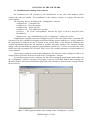
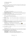
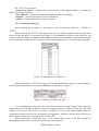
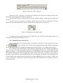
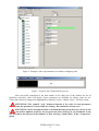
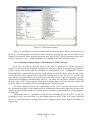
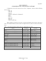
Scientific Production Company “Doza”
“Configurator” Software
Software User Manual
FVKM.001005-07 34 01
Cont ent
1. Purpose of the “Configurator” software …………………………….…………...….…
2. Conditions for using the software ………………………………………………….……
2.1 System requirements ………………………………………….……………..……...
2.2. Connection of the device to computer ………………………………………….….
3. Purpose of the software …………………………….…….…………………………..…
3.1. Installation and running of the software …………………………………..…….…
3.2. Working with the software ……………………………………………….…….….
3.2.1. Main window …………………………….…….………………..……………
3.2.2. Selection of the link type ……………………………………..……………....
3.2.3. Displaying state of the device ……………………………………..……….…
3.2.4. Editing parameters of the device ……………………………………………...
3.2.5. Reading archive of the device …………..………………………….…….…..
3.2.6. Working with spectra ……………………………………………………..…..
3.2.7. Editing the visual presentation mode …………………………………….…...
3.2.8. Working with the terminal window …………………………………………..
3.2.9. Saving the exchange images with the help of a “FILE” link type …………....
3.2.10. Using the “TCP/IP” link type ……………………………………………..…
3.2.11. Exiting the program ………………………………………………………....
4. Messages to operator ……………………………………………………………..……..
4.1. Information messages …………………………………………………………...…
4.2. Resolving unexpected problems …………………………………………………...
3
4
4
4
5
5
6
6
7
8
10
10
12
15
15
16
17
17
18
18
18
Appendix 1. The list of devices supported by the program “Configurator” ………………
19
FVKM.001005-07 34 01
2
This User Manual describes the purpose and capabilities of the “Configurator” software
(program) and the use of this software by operator. The “Configurator” software is a universal
configuring program for different devices and units (hereinafter – devices) manufactured by SPC
“Doza” and allows to obtain readings and state of the devices and setting of the internal parameters
within limits specified by the manufacturer. The “Configurator” software is sufficient for all tasks
related to the adjustment of supported devices except updating of the built-in software and certain
special service procedures. The “Configurator” software supports representation and editing of integer,
real, logical, text parameters and bitmaps in text representation, as well as special data structures such
as groups of parameters, data archives and measured spectra.
1. PURPOSE OF THE “CONFIGURATOR” SOFTWARE
The “Configurator” software (hereinafter – software or program) is intended for testing,
adjustment, calibration and analysis of data (including achieved data) received from devices
manufactured by SPC “Doza”. The software settings are stored in the ini-file – it makes possible to
change the software interface and support new modifications of devices without altering the program’s
code.
The “Configurator” software allows receiving information about the device’s state, displaying
information about possible errors and failures, performing adjustment and set certain parameters and
switching between modes of operation. Additionally the software allows obtaining the last
measurement data and saving in the archive for further analysis.
FVKM.001005-07 34 01
3
2. CONDITIONS FOR USING THE SOFTWARE
2.1 System requirements
The program can be used on computers with operating system Microsoft Windows (Windows
98 or higher) equipped with asynchronous serial port RS-232. For running the program with TCP/IP
protocol computer should be connected to the Ethernet network.
2.2. Connection of the device to computer
Two types of link can be used for communicating with the device: RS-232 and TCP/IP.
In the case of using RS-232 port connection between computer and device is performed with
the help of communication cable included in the delivery kit of the device. Connection is performed in
accordance with User Manual for the device. Two or more copies of the “Configurator” software can
be run concurrently for connection of several devices to the same computer provided that those copies
use different COM-ports.
ATTENTION! RS-232 interface is not intended for automation of the measurement
process, because RS-232 is used for adjusting and its intensive load in some cases can suspend
the measurement process directed to prevention of violation of the internal data integrity. For
automation of measurements it is necessary to use special interface intended for data exchange in
the automated system with correspondent software not included in the delivery kit.
When using the TCP/IP protocol computer and the device should be connected via Ethernet
network. The computer with the “Configurator” software and the device to be adjusted should be
located in the same segment of the Ethernet network. The IP address of the computer with the
“Configurator” software must correspond to the server IP address of the connected device. Connection
via TCP/IP is not possible if the Ethernet socket is not provided on the device. Connection via TCP/IP
does not duplicate possibilities of the RS-232 link; many parameters cannot be edited using this
protocol.
FVKM.001005-07 34 01
4
3. RUNNING OF THE SOFTWARE
3.1. Installation and running of the software
For installation use CD provided by the manufacturer or any other data medium, which
contains the software installer. The installation of the software consists of copying files into the
selected folder.
The following files are included in the “Configurator” software:
- configurer.exe – executable file;
- configurer.ini – file with settings;
- configurer.hlp – online help file;
- configurer.doc – User Manual for operator;
- devices.ip – file of the correspondence between the types of devices and their basic
IP-addresses;
- whatsnew.txt – log of modifications of the “Configurator” software by version.
In addition the program creates the Configurer.log file in the same folder where executable file
is located. The file is intended for logging of the data exchange process with devices. At first launch of
the program the Configurer.ini file is created in the system folder of the Microsoft Windows that
contains information about size and location of windows and other settings of the software. During
setting of the personal mode of parameters representation, another file – User.ini is created in the same
folder where the executable file is located. This User.ini file contains parameters of representation of
visual elements.
All necessary setting are saved in the configurer.ini file. Absence of the configurer.ini file or its
wrong location will result in incorrect work of the “Configurator” software.
To start the program run the configurer.exe file. After starting the program the main window of
the “Configurator” software will appear (see Figure 1). In case of working with the data exchange file
the main window will contain information from such a file, which was opened on the computer during
the last session.
Figure 1. Main program window after starting of the “Configurator” software
FVKM.001005-07 34 01
5
3.2. Working with the software
3.2.1. Main window
The main window is divided into two areas (parts). In the left part of the window the list of
available parameters is displayed for the connected device. In the right part of the window parameters
are displayed corresponding to the selected tab.
The standard menu of the program includes:
- File;
- Connection;
- Templates;
- Service;
- Help.
The “File” includes the following items:
“Re-read INI-file” – accepts changes made by the user in the file with settings;
“Read the unit image in a file” – allows saving information from all tabs into separate file for
further work with the “FILE” link type);
“Read also complex structures into image” – besides saving information from all tabs into a
file, this menu item allows saving received spectra and achieved data in separate files;
“Exit” – to exit the program select this menu item.
The “Connection” menu includes the following items:
“Link via RS-232” – selects the RS-232 link type (duplicates corresponding button on the
control panel);
“Link via TCP/IP” – selects the TCP/IP link type (duplicates corresponding button on the
control panel);
“Link with a file” – selects the “FILE” link type (duplicates corresponding button on the
control panel);
“Optimized reading of parameters” – this menu item allows excluding request of parameters
from the device that were received during last reading and were not subject to change;
“Refresh data” – allows updating of data received from a device;
“Transfer into unit” – transfers settings to a device (duplicates the button
);
“Preventive selection of connected device” – allows manual identification of the connected
device in case that serial number was read incorrectly.
The “Templates” menu: This menu is intended for service use by personnel trained at the
factory of manufacturer – SPC “Doza”.
The “Service” menu includes:
“Expanded access” – allows switching the program to service mode intended for adjustment
of certain engineering parameters. After switching to service mode in the left part of the window
bookmarks appear, which are not visible in the normal mode.
“Show debug window” – displays the terminal window;
“Default plotting“ – arranges all visual elements on tabs in order, “top-down”;
“Form edit mode” – switches to mode of editing positions of elements;
“Save appearance” – saves the layout of the form after editing in the “User.ini” file.
FVKM.001005-07 34 01
6
The “Help" menu includes:
“Context tip window” – displays area in the bottom of the program window, in which tips
appear when using a program;
“User Manual” – allows the operator to consult with short user manual;
“Manual” – access to files with reference information;
“About” – displays information about the program.
3.2.2. Selecting the link type
After launching the program it is necessary to select the link type (“RS-232”, “TCP/IP” or
“FILE”).
When selecting the “RS-232” link type, select also the COM-port number from the pull-down
menu to which the device is connected (see Figure 2). By default the COM-port used during the last
session is selected. When selecting form the COM-port some ports are dimmed, which means that they
are not currently available because of absence, incorrectly installed drivers or use by another program.
Figure 2. Pull-down menu “COM-port”
When selecting the “TCP/IP” link type, in the correspondent fields “Device” and “IP-address”
specify full net name of the device and its IP-address for the link (see Figure 3).
Figure 3. Selecting “TCP/IP” link type
It is recommended to input the name of the device first, then using a double click of the left
mouse button in the IP-address field the operator can get the default IP-address for this type and serial
number of the device. The device’s net name is defined by its type and serial number. Rules for
compiling net names of devices are presented in the Appendix 1. Moreover, the net name of the device
can be seen by connecting to it using the RS-232 interface.
When selecting the “FILE” link type, in the dialog window select a file with settings for
representation of its values, which were saved earlier (see Figure 4).
FVKM.001005-07 34 01
7
Figure 4. Selecting “FILE” link type
When the “FILE” link type is selected, by default the file with saved settings will be used,
which was used during the last session (if possible).
The selected link type, position and size of the program window remain the same until next
session.
In some cases it is necessary to monitor current values of the device’s parameters. For this
purpose use the auto update mode (“Auto” element on the control panel, see Figure 5).
Figure 5. Enabling the auto update mode
To enable the auto update mode tick the check box “ON” and specify the update interval in
seconds (on the Figure 5 this interval is 30 s).
3.2.3. Displaying state of the device
After selecting the item “Update of data” in the menu “Connection” or after mouse click on the
area
in the left part of the window, the program automatically identifies connected
device and arrange the tree of available configuring tabs for this device; see example on the Figure 6.
For each tab several parameters for representation and adjustment can be defined depending on
the device type. For access to parameters click on corresponding tab in the tree. The progress bar will
appear (see Figure 7), which represents the process of data transfer. After completion of the transfer
the window will disappear. After disappearance of the window check the correctness of processing of
the query. If the query was processed incorrectly the error message will appear in the information bar
(in the bottom of the program window) and the bar will be highlighted by yellow colour. If this is the
case it is necessary to repeat the operation and provide correct connection in accordance with the
selected link type.
FVKM.001005-07 34 01
8
Figure 6. Example of the representation of available configuring tabs
Figure 7. Progress bar of data transfer process
After successful completion of the data transfer in the right part of the window the list of
parameters and their values will appear. Some parameters are available for editing, some are not.
Values that cannot be changed are highlighted by dark blue colour, editable values – by black colour.
ATTENTION! The symbols “@@” displayed instead of the value of some parameter
indicate that this parameter is inaccessible for reading. This situation is not an error.
ATTENTION! If the auto update mode is disabled then data from the device shown in the
current tab will be updated (read) by the program only after clicking on any bookmark in the
tree (located in the left part of the window) or after selecting “Update data” in the “Connection”
menu.
FVKM.001005-07 34 01
9
3.2.4. Editing parameters of the device
Many parameters of the device represented by the program are editable (corresponding values
are shown in black). To change the parameter value it is necessary to edit it in corresponding field and
then write to the device. Writing is performed by pressing the button
, which became active
after the value is changed, or by selecting “Transfer to device” from the “Connection” menu.
After completion of the transfer process, check the correctness of the query processing by text
message and colour of the information bar (in the bottom of the program window). In case of an error
during data transfer the bar will be highlighted in yellow; the text of the message will indicate the
cause of an error.
The “FILE” link type is intended for reviewing and checking and does not allow transferring
data.
3.2.5. Reading archive of the device
In order to read the data archive from the device (provided that this function is available for the
device) select the “Archive” tab and in the right area of the window check parameters to be read; see
an example in the Figure 8.
Figure 8. “Achieve” tab
After all necessary parameters were checked select the starting and finishing records for
reviewing of the archive, as well as increment used for data sampling, and then press the
button.
In the “Archive” window archived records for selected parameters will be presented (see
Figure 9).
FVKM.001005-07 34 01
10
Remember that record numbers are relative and arranged in the following order: the first record
corresponds to the last measurement, the second record – to the previous measurement made before the
last one and so on.
Figure 9. “Archive” window
Received data can be exported to Excel format for analysis (requires Microsoft Excel); to
exported data click on the button “Export to Excel”. The 10).
Figure 10. Archived data in the Microsoft Excel format
The program also offers capabilities of graphic representation for the selected parameters. For
FVKM.001005-07 34 01
11
displaying of the graph select the desired parameter from the table and click on the button “Show
graph”. Alternatively you can select “Show graph” item from the context menu; to show the menu
click with the right mouse button on the desired parameter.
In the window that will appear you can see the desired parameter as a function of time and
calculate cumulative and average values for total number of represented measurements (see Figure 11).
Figure 11. “Graph” window
Alternatively it is possible to obtain the average value of the desired parameter by clicking on it
with the right mouse button in the table in the “Archive” window and by selecting the “Calculate
average” from the context menu. The window “Average value” will be displayed with the average
value in it.
If data presented in the table of the “Archive” window have to be saved press the button “Save
to file” and in the appeared dialog window specify the desired folder (path to the file). Saved file will
have an extension *.daf. The content of the file can be accessed using special software (for example,
“DAFViewer”).
3.2.6. Working with spectra
For certain devices the program allows to display energy spectra of the main and background
channels (see Figure 12). For reading of a spectrum from the device go to the “Spectra” tab.
FVKM.001005-07 34 01
12
Figure 12. General appearance of the “Spectra” tab
After pressing the “Read” button on the panel (see Figure 13) the program reads and plots the
energy spectrum of radiation (see Figure 14). For acknowledgement of the spectrum correctness the
message is show nearby: “Spectrum was read correctly”.
Abscissa represents the energy of radiation (keV); corresponding number of counts (pulses) is
shown by the ordinate.
Figure 13. Spectrum editing panel
FVKM.001005-07 34 01
13
Figure 14. Energy spectra for main and background channels
In case the error occurred during data transfer and the spectrum was not received, retry to read
it by clicking on the “Read” button again.
To change the scale along the abscissa use
buttons, along the ordinate buttons,
accordingly.
If necessary, the graph can be shifted to the left of to the right with the help of
buttons.
For saving of the modified spectrum press the button “Save” and in the in the appeared dialog
window specify the desired folder (path to the file). Saved file with spectrum will have an extension
*.sp. The content of the file can be accessed using special software (for example, “SpecView”).
Pointing by mouse cursor on any point in the spectrum displays channel number for this point
(Chanel=), corresponding energy (Energy= ) in keV, and number of counts for this energy (Height= )
under the mouse cursor.
The program also offers the manual mode of energy calibration. For performing manual
calibration do the following:
- determine channel numbers corresponding to full absorption peaks selected for calibration;
- click by the right mouse button on the first selected point of the spectrum and in the context
menu select the item “Set the first calibration point”; in the dialog window that will appear input the
energy for selected full absorption peak;
- repeat the procedure with the second point in the spectrum by selecting the item “Set the
second calibration point”.
FVKM.001005-07 34 01
14
With the help of an item “Abscissa in channels” in this context menu setting for calibration of
this axis can be switched between energy units (keV) and ADC channels.
In the service mode (if the item “Expanded access” in the menu “Service” was activated) the
operator can edit calibration coefficients A and B for main and background detectors (if applicable for
the device) as well as write coefficients to the device.
3.2.7. Editing the visual presentation mode
The “Configurator” software allows customizing of the parameters representation on each tab.
For editing the form and position of elements select the item “Form editing mode” from the “Service”
menu. After that all elements in the right part of the program window can be relocated from one
position in the panel to another by mouse. To do this point on the desired element with mouse cursor
then press and hold the left button while dragging the element to the desired position. If the visual
element is dragged outside the panel area then it will pop-up over the window and will be accessible
for editing of the form. In this mode the operator can change the size (width and height) of the visual
element. After the form editing is complete drag the element back to the panel.
Changes can be saved for future use. For doing this select the item “Save layout” from the
“Service” menu.
3.2.8. Working with the terminal window
In some cases reviewing of the log of the data exchange with the device may be necessary or
send a repeated request for some parameter. In this case function that shows the terminal window is
suitable (see Figure 15). The terminal window is opened by selecting the item “Show tracing window”
from the “Service” menu.
The terminal window is divided into three parts. The left part contains the list of evoked
parameters and their last values. Double clicking with left mouse button on any of these strings in this
area will result in re-reading of the parameter value. The right area is a window in which the log of the
data exchange is recorded. The outgoing data are marked with the “>”, while the received data are
marked with “<”. The bottom area is for independent commands. Strings that were input here can be
transferred to the device at presentation layer of the data exchange protocol. For example, it is
necessary to request the current date and time again. For this purpose input the string
“DATETIME=??” in the area for independent commands. To transfer this request to the device in the
area of the input string activate the context menu (using right mouse button) and select the item “Send
content as is”. At that in the right area of the terminal window the result of request will appear, for
example: “<DATETIME=23/01/2007 15.22.40;”.
FVKM.001005-07 34 01
15
Figure 15. The terminal window
There is a possibility to save the terminal window content for future analysis of functioning of
the device. For this purpose activate the context menu by pressing the right mouse button in the
window of represented values and select the menu item “Save to file”. Here the operator can also clear
the list by selecting “Clear”. Similar capabilities are available for the data exchange window.
3.2.9. Saving the exchange images with the help of a “FILE” link type
It is often necessary to save the image of the device’s parameters for further analysis by
experts. For this purpose the possibility is provided of successive reading and saving of all parameters
(except archives and spectra) that are accessible for representation by the “Configurator” software.
This possibility is available through selection of the menu item “Read the device image in a file” of the
“File" menu. Successive requests will be sent to the connected device (via “RS-232” or “TCP/IP” link
type) and the user will be asked to specify the file for saving the image of the data exchange by means
of the Microsoft Windows standard dialog “Save as”. The image file can also be formed by selecting
the item “Save to file” from the context menu of the terminal window. However only those values will
be saved, which were requested before activating the above mentioned menu.
For further analysis of the device’s functioning use the “FILE” link type and open the saved
file. At that the interface of representation will be formed that corresponds to that were present in the
program window during reading (on condition that the settings for representation of visual parameters
are identical).
Additionally there is a possibility to log the data exchange process in a file. To use this
possibility set “tick” next to the item “Log the reading protocol in a file” of the “File” menu. After that
the list of events during data exchange between the program and the device will be compiled in a
separate file.
FVKM.001005-07 34 01
16
3.2.10. Using the “TCP/IP” link type
When using the TCP/IP protocol computer and the device should be connected via Ethernet
network. In this case there is the only tab in the tree – “UDP”. Fixed set of main parameters is
represented on this tab.
ATTENTIO N! Connection via TCP/IP does not duplicate possibilities of the RS-232
link; many parameters cannot be edited using this protocol.
3.2.11. Exiting the program
To exit the program click on the “close window” button of the main program window or select
“Exit” in the “File” menu or use the key combination Ctrl+X.
FVKM.001005-07 34 01
17
4. MESSAGES TO OPERATOR
4.1. Information messages
Information messages are divided into two groups: The first group – messages about program
flow, the second group – information from the device.
The first group of information messages includes messages in the status bar of the main
program window and of the progress bar window.
Messages in the status bar of the main program window are as follows:
- “Access via COM-port is active” – RS-232 link was activated;
- “Access via TCP/IP is active” – TCP/IP link was activated;
- “Connection was not established” – connection was selected erroneously (for example,
non-existent COM-port);
- “Connection was established, no link with the device” – connection was not successful via
selected channel, attempting to update information;
- “Device XXX page YYY” - successful reading of information from the device XXX on the
properties tab YYY;
- “Data were not read from the device properly” – repetitive error in the process of receiving
data from the device or incorrect structure of the file “configurer.ini”;
- “All changes were successfully transferred” – information was correctly sent to the device;
- “Some changes were not successfully transferred” – data transfer for several parameters
was not confirmed.
The progress bar window indicates the information quantity in per cents that was transferred to
the device or read from the device.
Information messages of the second group depend on the type of device, its state and mode of
operation. Information is sent to the visual elements of the right panel of the main program window in
the form of numerical values, position of the button and “tick” for simple parameters and in the form
of a table (for archives) and graph (for spectra) in separate windows.
Error messages are highlighted by the yellow background of the displayed text.
4.2. Resolving unexpected problems
Thoroughly reread this User Manual. The online help can also be used for this purpose; it is
available by pressing F1 button on the keyboard. Contact the technical support service of the
SPC “Doza”.
The “Cofigurator” software is actively improved; please do not hesitate to address your
opinions and suggestions to developers for correcting and further development of this software.
Updated and corrected versions of the “Cofigurator” software, as well as ini-files are available on the
site of manufacturer www.doza.ru in the “Equipment” section (see “Software”).
FVKM.001005-07 34 01
18
Appendix 1
LIST OF DEVICES
SUPPORTED BY THE “COFIGURATOR” SOFTWARE
Configuration of the ini-file ensures the use of the “Cofigurator” software with the following
devices (units):
- UDA-1B;
- UDG-1B;
- UDI-1B;
- UDGB-1T, UDGB-01T1, UDGB-01T2;
- BOP-1;
- BOP-1c;
- BOP-1TA;
- BOP-1M;
- UDGP-01 (BOP-1sp).
When working via TCP/IP it is necessary to specify the IP-address and net name of the device
(unit). The default IP-addresses and net names for supported devices (units) are shown in the table 1
below.
Table 1. The default IP-addresses and net names for supported devices (units)
Device
IP-address
Net name
BOP-1;
192.168.1. XXX
BOP-1 XXX
BDMG-100 (connected to BOP-1)
192.168.1. XXX
BDMG-100 XXX
BDMN-100 (connected to BOP-1)
192.168.1. XXX
BDMN-100 XXX
UDA-1AB;
192.168.3. XXX
UDA-1AB XXX
UDG-1B;
192.168.2. XXX
UDG-1B XXX
UDGT-1T
192.168.4. XXX
UDGT-1T XXX
UDGT-2T
192.168.5. XXX
UDGT-2T XXX
BOP-1c;
192.168.7. XXX
BOP-1S XXX
BOP-1sp;
192.168.10. XXX
BOP-1SP XXX
BOP-1M;
192.168.8. XXX
BOP-1M XXX
UDMG-100 (connected to BOP-1M)
192.168.8. XXX
4.2.XXX
UDMN-100 (connected to BOP-1M)
192.168.8. XXX
5.2.XXX
UDI-1B;
192.168.9. XXX
UDI-1B XXX
Note - XXX is the serial number of the device (unit) by the manufacturer’s numeration system
FVKM.001005-07 34 01
19