1
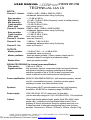
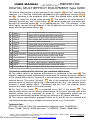
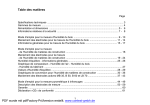
USER MANUAL
PODIUM MXV-P200
SAFE OPERATION AND GENERAL RECOMMENDATIONS
Keep away from water and humidity, weather, electrical
discharge and strong sun or heat radiation.
For adequate cooling the ambient temperature should not
exceed 35°C. Do not operate immediately after changing the
ambient temperature. Particularly when moving from cold to
hot and humid environment, the metal parts and electronic
components can be affected by condensed water. Wait for about
15 min. until the PODIUM MXV-P will be adapted to the ambient
temperature.
35°C
max.
Make sure to connect the PODIUM MXV-P to the appropriate
supply voltage and quality mains supply. Use the cable that is 230V~
supplied with the PODIUM MXV-P, the connection must be 3- 50-60Hz
pole grounded. If you are uncertain about it, grounding should
be checked by an expert. To avoid risk of injury (i.e. tripping
over cables) or damaging cables and the device, the connected
lines should be placed very careful.
Do not operate the PODIUM MXV-P and the connected devices
near the strong electromagnetic fields and/or high voltage equipment, like emitting antennas (i.e. for instance mobile telephone),
large transformers, motors and generators, neon lights.
Do not expose yourself to excessive hearing of volume or high
sound pressure levels. Be aware of the possible consequences
for your hearing. Try allways when possible to place the PODIUM
MXV-P effective to improve the listening volume for the audience
while reducing the sound pressure level in the near field to the
level that is necessary. Normally the PODIUM MXV-P should be
placed at the same height as the ears of the audience.
For servicing or repair refer to an authorized expert, avoid
unauthorized alteration, do not try to open or disassemble any
screw or connection.
For damages that are caused by unauthorized alteration or
misuse we refuse any responsibility.
3 YEAR
WARRANTY
A.M.P., D-66111 Saarbruecken - Germany, Tel: +49 681 9686881, Fax: +49 681 62495 , www.cromacord.com
RCPMXVP200-E001-20030403 * All rights reserved
PDF wurde mit pdfFactory-Prüfversion erstellt. www.context-gmbh.de
PAGE 1/6
USER MANUAL
PODIUM MXV-P200
OPERATING ELEMENTS AND FEATURES
1
Channel 1- volume control with coupled trim gain
control (SAGA = Semi automatic gain adjust)
2
Channel 1 - Effect, controls the
volume of the signal to be sent to
the effect unit
3
Channel 1 - Bass equalizer control
4
Channel 1 - frequency control of
the semiparametric mid-frequency
equalizer
22 23 1
2
3
4
5
6
7
8
ch1-level
eff-send
bass
mid-freq
mid-level
treble
line
PODIUM
9
mic
ch4-level ch5-ret.
ch2-level
eff-send
bass
treble
line
Filter
master
balance
9
5
master-vol
13
10
mic
OFF
ch3-level
eff-send
bass
treble
line
ON
range
1
11
9
P 200
stereo
effect
return
effect
mic
13
5
mode
1
5
Channel 1 - mid-equalizer volume
control
6
Channel 1 -Treble equalizer control
7
Channel 1 - Input sensitivity selector of the
preamplifier, "mic" for low , "line" for higher input
level
26 Channel 3 - balanced 3- pole input socket for 6,3mm
jack plug
8
Channel 2 - Bass equalizer control
27 Channel 4 - balanced 3- pole input socket for 6,3mm
jack plug
9
Channel 2 - Treble equalizer control
28 Channel 5 - balanced 3- pole input socket for 6,3mm
jack plug
12
36 35 21 20 19 18 17 16 15 14 13
10 Channel 2 - Input sensitivity selector of the preamplifier, "mic" for low, "line for higher input level
11 Channel 2 - ffect, controls the volume of the signal
to be sent to the effect unit
29 Mix-output of the levels adjusted by the effect
controls, "mix"= from the output of the integrated
effect device (option),"dry" = without effect or from
the input of effect-device.
13 Channel 3 - Treble equalizer control
30 2 preamplifier master outputs before filter equalizer
switch and the signal controller/ limiter, "post" = after
master volume control, "pre" = before master volume
control.
14 Channel 3 - Bass equalizer control
31 Output for extension loudspeaker min. 8 Ohm
15 Channel 3 - Effect, controls the volume of the
signal to be sent to the effect unit
32 Mains fuse holder 250V/5x20mm 1 A slow-blow, contains 1 spare fuse for replacing
12 Channel 3 - Input sensitivity selector of the preamplifier, "mic" for low, "line for higher input level
16 Channel 3 - Volume control with coupled trim gain
control (SAGA = Semi automatic gain adjust)
33 Mains inlet connector (EN60 320-1 for cold condition)
34 lighting mains power switch
17 Channel 2 - Volume control with coupled trim gain
control (SAGA = Semi automatic gain adjust)
35 not in use, reserved for optional upgrading
18 Channel 5 - volume control
37 blind plate 1, reserved for optional accessory module
19 Master volume control
38 blind plate 2, reserved (vid. supr.)
20 Channel 4 - volume control
39 blind plate 3, reserved (vid.supr.)
36 not in use, reserved for optional upgrading
39 38 37
21 Program selector 1 for integrated effectdevice type 0200
Xin-ch1
22 Program selector 2 for integrated effectdevice (option)
Xin-ch2
Xin-ch3
ATTENTION ! DO NOT CONNECT !
READ INSTRUCTION TO OPERATE
230V 50/60Hz
1 A T/
LS 8Ω
Made in Germany by AMP
Acoustic Music Performance
23 Filter-equalizer switch to cut mid -low
frequency at 350 Hz
master eff-send
ch5-ret
dry
hot
pre
post
mix
cold
L LS 8Ω R
mode
ex
ON OFF
24 Channel 1- balanced 3-pole input socket
for 6,3mm jack plug
25 Channel 2- balanced 3-pole input socket
for 6,3mm jack plug
Xin-ch4
ch 4
hot
cold
ch 3
hot
cold
ch 2
hot
cold
ch 1
hot
cold
eff-L-ins
eff-R-ins
stereo out L ch1-ins
in
in
out
out
ON OFF
prefad R
in
out
ON OFF ON OFF
phantom
ch 3
34 33 32
ch 2
ch 1
31 30 29 28 27 26 25 24
A.M.P., D-66111 Saarbruecken - Germany, Tel: +49 681 9686881, Fax: +49 681 62495 , www.cromacord.com
RCPMXVP200-E002-20030403 * All rights reserved
PDF wurde mit pdfFactory-Prüfversion erstellt. www.context-gmbh.de
PAGE 2/6
USER MANUAL
PODIUM MXV-P200
OPERATION INSTRUCTIONS (page 1)
1. Start position before switching on:
In order to avoid unpredictable operation conditions, as idle noise, feedback, distortion,
etc. the PODIUM MXV-P should be set to start position before switching on:
19 ,"ch - level" 11, 16
16 , 17,
17 18
18 , 20
20 , "eff-send" 22 , 11
11 , and 15
15 set to
1.1. "master-vol" 19
zero level, left terminal.
3 , 5
9 , 13
13 , 14
14 in position center groove
1.2. Equalizer controls 3
5, 6, 8, 9
10 , 12
12 in position "line"
1.3. Sensitivity selectors 77 ,10
23 in position "off"
1.4. "Filter" switch 23
Now you can switch-on the mains power supply 34
2. Input connection:
Depending on the instrument or signal source and the required features, there are
different possibilities of using up to 5 instruments at the same time. Plug in the cable
to the appropriate input connector :
28 suited for sources and instruments with high output
27 or channel 5 28
2.1. channel 4 27
level, if there is no need to use an internal equalizer and also no need for adding an
internal effect to be mixed down, for instance: instruments with preamplifier and/or
equalizer, like keyboard, CD player, etc.
25 or channel 3 26
26 for sources and instruments that can not be
2.2. channel 2 25
amplified as stated before 2.1.
24 for sources and instruments, when a semi-parametric mid
2.3. Channel 1 24
equalization is required.
2.4. Channel 1, 2, or 3 suited for microphones with low output level with possibility to
make balanced connection with adapter-cable 3-pole jack to XLR-female
3. Adjusting the signal:
The individual volume of each channel is to be adjusted with the controls "ch-level" 11 ,
17 18,
18 20,
16 17,
20 the required volume of the total mix of the individual channels is to be
16,
19 .
adjusted with "master-vol" 19
3.1. Start adjusting the choosen channel and turn clockwise the appropriate control "ch19 until the signal can be heard. Try to adjust or
level", as well as the control "master-vol" 19
19 in order to observe the sound quality of
limit for your ease the hearing-volume with 19
the output. Turn slowly the control "ch-level" clockwise and increase the volume as long
as the signal is clean and undistorted but not over the discontinued mark at the end of
the scale. When you begin to perceive any distortion, turn back the control until the
distortion disappears. Test the result then also with a signal that could be typically the
loudest possible to be expected and repeat the procedure if necessary.
19 to the
3.2. Check now maximum volume performance by turning the control 19
discontinued mark at the end of the scale. If the level is not enough, use one of the
channels 1, 2, or 3 for this signal, put the appropriate sensitivity selector to position "mic"
and repeat the procedure 3.1. if necessary.
3.3. If desired, adjust the equalizer controls of the appropriate channel at your
convenience. Particularly when setting one or various equalizer controls to considerable
high amplification gain, it may become necessary to reduce or to readjust the appropriate
"ch-level" corresponding to the procedure 3.1.
A.M.P., D-66111 Saarbruecken - Germany, Tel: +49 681 9686881, Fax: +49 681 62495 , www.cromacord.com
RCPMXVP200-E003-20030403 * All rights reserved
PDF wurde mit pdfFactory-Prüfversion erstellt. www.context-gmbh.de
PAGE 3/6
USER MANUAL
PODIUM MXV-P200
OPERATION INSTRUCTIONS (page 2)
4. Connecting an external effect-device:
29 to the input of the effect-device, as well as it's output to the
Connect the socket "eff-send" 29
28 . Adjust at your convenience with "eff-send" 22 , 11
11 , and 15
15 the relative
input "ch 5-ret" 28
intensity of the effect for each individual channel. First of all set the appropriate "eff-send"
control of the instrument that can be expected to require the highest intensity close to
maximum, adjust at your convenience the total mix of the required intensity with the control
"ch5-ret" 18
18. Then adjust the required effect-intensity of the other channels with their
appropriate "eff-send" controls.
.
5. Using the preamp outputs:
30 is delivering 2 independant unbalanced preamplifier
The 3-pole "master-out" socket 30
outputs that can be used at the same time with a cable <3-pole jack to 2xmono jack> .
Particularly for avoiding hum generated by ground loops, the connection to other
amplifiers and devices that are grounded through a 3-pole mains connection (multiple
grounded) should be splitted by using a DI-BOX or a suited audio-transformer.
19 it works as if
5.1. The signal of the pin "pre" does never depend on "master-vol" 19,
"master-vol" would be set at maximum. The users hearing-volume towards the built-in
19
amplifier can be adjusted independently at any moment with the control 19.This
is
particularly suitable e.g. when connecting to a P.A. sound reinforcement system, while
using the amplifier as active monitor or when connecting to a recording-device while
keeping the recording level constant.
5.2. The signal of the pin "post" is always depending proportionally on the control
19 . This is particularly suitable when connecting other amplifiers that will be
"master-vol" 19
controlled together as slaves.
6. Connecting extension cabinet:
Make sure that the impedance is minimum 8 Ohm and that the technical condition of the
speaker-system (i.e. risk of wrong impedance due to failure of a tweeter) and it's cables
and connectors ( i.e. risk of short circuit due to damaged components !) is perfect. Plug
31 .Do not
the speaker cable (min. 2x0,75mm² diameter) with 2-pole jack into the socket 31
use microphone or instrument cables.
A.M.P., D-66111 Saarbruecken - Germany, Tel: +49 681 9686881, Fax: +49 681 62495 , www.cromacord.com
RCPMXVP200-E004-20030403 * All rights reserved
PDF wurde mit pdfFactory-Prüfversion erstellt. www.context-gmbh.de
PAGE 4/6
USER MANUAL
PODIUM MXV-P200
TECHNICAL DATA
INPUTS:
Channel 1 - line/mic
-20dB to +6dB / -50dB to -20dB /2x 160KΩ
unbalanced, balanced when using 3-pole plug
+ - 13 dB/ at 100 Hz
Bass equalizer
+ 15 dB/ -13 dB at 1,6KHz (frequency control at middle position)
Mid intensity
375 Hz to 5,5 KHz
Mid frequency
+ 12 dB/-15 dB at 10 KHz
Treble equalizer
post volume control
Effect send
Channel 2 - line/mic -20dB to +6dB / -50dB to -20dB /2x 80KΩ
unbalanced, balanced when using 3-pole plug
+ - 13 dB/ at 100 Hz
Bass equalizer
+ 12 dB/-15 dB at 10 KHz
Treble equalizer
post volume control
Effect send
Channel 3 - line/mic same as Channel 2
-3 dB bis + 7 dB / 2x 60 KΩ
Channel 4 - line
unbalanced, balanced when using 3-pole plug
same as Channel 4
Channel 5 - line
OUTPUTS:
Master prefader:
Master postfader:
Master effect:
+ 16 dB at 10KΩ − or + 4 dB at 600Ω
unbalanced, short circuit proof
same as master prefader (Option: master outputs can be
internally bridged to configure one balanced output)
same as master prefader
SIGNAL PROCESSING (for internal power amplification):
6 dB cut at 350 Hz
Filter switch:
fully automatic, dynamic compressor-limiter and signal enhancer
Signalcontroller:
with dynamic frequency-response-matching and complex
selective regulation of up to 30 dB, for best psychoacoustic
results of acoustic music instruments and microphones.
Power amplification: 60/90/120 Watt RMS 8Ω/RMS 4Ω (with extension speaker- cabinet
min.8Ω connected)/music power, protection-circuits against
switching-on noise, over-heat and short circuit
Speakers:
2-way system with 8" low-mid speaker and dyn. high frequency
driver/horn, 98 dB/1W/1m, frequency range 55-20000 Hz
Power supply:
230V~/50-60 Hz/ 125 VA, mains fuse 1A slow-blow
(can be internally changed to 115V~/50-60Hz/125VA, 1,6A slow-blow)
Cabinet:
16mm high-density particle board, spatter finish RAL 4004 (~dark
purple-ruby), protective front of perforated sheet metal 1,5mm,
prepared to mount optional std. flange for speaker-stand on up to
3 sides/2axis and to add optional protecting hard cover for transportation. Dimensions: 396mm x 290mm x 265mm, Weight:11kg
A.M.P., D-66111 Saarbruecken - Germany, Tel: +49 681 9686881, Fax: +49 681 62495 , www.cromacord.com
RCPMXVP200-E005-20030403 * All rights reserved
PDF wurde mit pdfFactory-Prüfversion erstellt. www.context-gmbh.de
PAGE 5/6
USER MANUAL
PODIUM MXV-P200
DIGITAL MULTIEFFECT EQUIPMENT type 0200
29 pin "dry" coming from
The built-in effect-device is wired internally to the output's 29
11
channels 1 to 3 that are individually adjustable by their appropriate controls 22, 11,
15
and 15.
Referring to the programm chart below, the desired effect mode can be
21 The output of the effect-device is
selected by using the 16-step rotary encoder 21.
29 and at the same time connected also
internally wired to pin "mix" of the socket 29
28
through the switched socket 28 to it's appropriate pin "hot". The intensity of the
effect signal returned through channel 5 can be adjusted and mixed to the master
18
signal with the appropriate control 18.
1
2
3
4
5
6
7
8
9
10
11
12
13
14
15
16
Delay 1
Room 3
Room 2
Plate 3
Chorus
Plate 1
Room 1
Plate 2
Flange
Rotary Speaker
Hall 1
Chorus/Room1
Delay 2
bypass
Hall 2
Chorus/Room 2
125 ms slapback delay for vocals and guitars
Warm room for guitars and rhythm instruments
Ambience for acoustic mixes and synth sounds
Short vintage plate reverb for snares and guitars
Chorus for guitars and pianos
Classic plate reverb for lead vocals and instruments
Hardwood studio for acoustic instruments
Sizzling bright plate reverb for vocals and drums
Flanger for jet wash effects
Rotary speaker emulation for organs and guitars
Bright hall reverb for drums, guitars, and vocals
Chorus with reverb for guitars, synths, and pianos.
190ms delay for percussive arpeggios
No effect, output signal is a identical digital copy
Warm hall for acoustic guitars, pianos and vocals
Auto-wah guitar effect reverb for lead instruments
Connecting additional effect-devices and combined applications:
28 .The
A) The output cable of an external effect-device is connected to the input 28
socket's integrated switch automatically disconnects the internal routing of channel 5
to the internal effect-device. Channel 5 is now receiving only the output signal of the
29 has to be connected to the input of the
external device. The output "eff-send" 29
external device by using a 3-pole plug. Connected with pin "dry", the external device
receives a signal without effect. Connected with pin "mix", the external device
receives the output signal of the internal device.
28 . The
29 is connected to pin "hot" of the socket 28
B) Pin "mix" of the socket 29
internal effect-device can be used as stated before. At the same time the input of an
external device can be connected as mode A), it's appropriate output can be
returned and individually adjusted through any channel or by various channels..
C) The various combinations proposed before at A) and B) can be selected and
controlled externally using a suitable connection device, e.g. a foot switch.
Technical data:
ADC,DAC: 24 bit, 44,1 KHz, 64x oversampling, frequency range : 20-20000 Hz
Noise: -105 dB, THD+N: -95 dB, Input max ! : +10dB/2KΩ , Output: +20dB/10KΩ
A.M.P., D-66111 Saarbruecken - Germany, Tel: +49 681 9686881, Fax: +49 681 62495 , www.cromacord.com
RCPMXVP200-E006-20030403 * All rights reserved
PDF wurde mit pdfFactory-Prüfversion erstellt. www.context-gmbh.de
PAGE 6/6