1
USING THE AXOCLAMP-2B
Page 23
Discontinuous Single-Electrode Voltage Clamp Mode - dSEVC
Headstage Selection
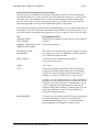
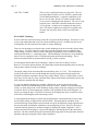
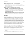
This tutorial uses the HS-2A-x0.1LU and HS-2A-x1LU headstages shipped standard with the Axoclamp2B. For other suitable headstages see Headstages in REFERENCE GUIDE: PRINCIPLES OF
OPERATION. Both headstages are used in the tutorial to illustrate the effects of properly adjusting
the voltage clamp. In an actual recording situation a single microelectrode is used.
Initial Instrument Settings
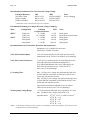
Before starting, set the panel controls to the "default" settings.
Connections
Headstages
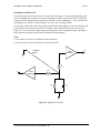
Connect the HS-2A-x0.1LU headstage to the ME1 PROBE connector and the HS-2A-x1LU headstage
to the ME2 PROBE connector on the back panel of the Axoclamp-2B.
Model Cell
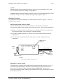
Connect both headstages to the CLAMP-1U model cell (the MCW-1U model cell can be used if you
wish to simulate the use of a patch pipette). The HS-2A-x1.0LU records the true membrane
potential and is used as part of the demonstrations indicating the correct and false settings of the
clamp.
Connections to interface
Monitor the ME1 output from 10 Vm and Im. Monitor the ME2 output from V2. The second
microelectrode, ME2 is used to measure the true membrane potential. Connect the outputs to the
A/D interface. Although a signal conditioner is not needed for this tutorial, it is useful for filtering
the output of V2. A second- or higher order low-pass filter (e.g., a CyberAmp 320) can be used.
Connections to the Oscilloscope
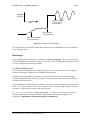
Connect the MONITOR output to one of the input channels of the monitor oscilloscope (which
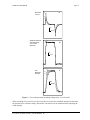
need not be a high quality type) with the gain at 100 mV/div (= 10 mV/div input referred). The
output of the SAMPLE CLOCK is used to trigger the oscilloscope.
Acquisition and Command Setup
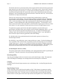
Use one of the programmable logic outputs (TTLs) of your computer interface to synchronously apply
a delayed logic pulse of 2.5 ms duration to the STEP ACTIVATE input on the rear of the Axoclamp2B. The step command value on the thumbwheel will be directed to the circuit designated on the
DESTINATION switch only when the toggle is switched to EXT.
Alternatively, you could use D/A converters to send commands to the EXT. VC COMMAND input on the
rear panel. Keep in mind that the input is simply summed with the commands generated by the internal
command circuitry. The rear current command inputs are continually active and are unaffected by the
position of the command DESTINATION switch. For this reason check that "zero volts" of the command
signal truly is zero volts, otherwise an offset current will appear through the microelectrode.
AXOCLAMP-2B, COPYRIGHT 1997-2003, AXON INSTRUMENTS, INC.