1
QuadroE1/T1 Manual II: Administrator's Guide
Edition 1, SW Release 3.0.49 and higher, January 2006
QuadroE1/T1 (SW Version 3.0.x)
QuadroE1/T1 Manual II: Administrator's Guide
Table of Contents
Manual I: see Installation Guide
Step-by-step guide to install and configure Quadro basically.
Manual II: Administrator's Guide
About this Guide................................................................................................................... 4
0H
7H
Quadro’s Graphical User Interface ....................................................................................... 5
1H
78H
Administrator’s Main Page ............................................................................................................... 5
2H
79H
Recurrent Buttons............................................................................................................................ 6
3H
80H
Recurrent Functional Buttons .......................................................................................................... 6
4H
81H
Entering a SIP Addresses correctly .................................................................................................. 6
5H
82H
Administrator’s Menus ......................................................................................................... 7
6H
83H
System Menu ................................................................................................................................... 7
7H
84H
System Configuration Wizard ............................................................................................................................. 7
Internet Configuration Wizard ............................................................................................................................ 9
Status ........................................................................................................................................................... 12
General Information ................................................................................................................................... 12
Network Status.......................................................................................................................................... 12
Lines Status .............................................................................................................................................. 14
Hardware Status........................................................................................................................................ 15
SIP Registration Status............................................................................................................................... 16
H323 Registration Status ............................................................................................................................ 16
IP Routing Configuration.................................................................................................................................. 16
Configuration Management .............................................................................................................................. 18
Update Configuration ...................................................................................................................................... 19
Events .......................................................................................................................................................... 20
Time/Date Settings......................................................................................................................................... 24
Mail Settings .................................................................................................................................................. 25
Firmware Update ............................................................................................................................................ 26
Networking Tools............................................................................................................................................ 27
Diagnostics .................................................................................................................................................... 28
Automatic Provisioning .................................................................................................................................... 28
Features........................................................................................................................................................ 29
Upload Language Pack .................................................................................................................................... 29
8H
85H
9H
86H
10H
87H
1H
8H
12H
89H
13H
90H
14H
91H
15H
92H
16H
93H
17H
94H
18H
95H
19H
96H
20H
97H
21H
98H
2H
9H
23H
10H
24H
10H
25H
102H
26H
103H
27H
104H
28H
105H
Users Menu .................................................................................................................................... 30
29H
106H
User Management .......................................................................................................................................... 30
SIP Advanced Settings ............................................................................................................................... 37
H323 Advanced Settings ............................................................................................................................. 37
Extension Codecs....................................................................................................................................... 38
Change Admin Password ................................................................................................................................. 39
30H
107H
31H
108H
32H
109H
3H
10H
34H
1H
Telephony Menu............................................................................................................................. 40
35H
12H
Call Statistics ................................................................................................................................................. 40
RTP Statistics ............................................................................................................................................ 41
SIP Settings................................................................................................................................................... 42
H323 Settings ................................................................................................................................................ 42
RTP Settings .................................................................................................................................................. 43
NAT Traversal Settings .................................................................................................................................... 44
Line Settings.................................................................................................................................................. 47
Loopback Settings...................................................................................................................................... 48
E1/T1 Settings ............................................................................................................................................... 49
Gain Control .................................................................................................................................................. 57
Call Routing ................................................................................................................................................... 57
VoIP Carrier Wizard ........................................................................................................................................ 63
RADIUS Client Settings ................................................................................................................................... 65
Dial Plan Settings ........................................................................................................................................... 66
36H
13H
37H
14H
38H
15H
39H
16H
40H
17H
41H
18H
42H
19H
43H
120H
4H
12H
45H
12H
46H
123H
47H
124H
48H
125H
49H
126H
Internet Uplink Menu ..................................................................................................................... 67
50H
127H
PPP Dial Settings ............................................................................................................................................ 67
Advanced PPP Settings ............................................................................................................................... 67
ISP Authentication Settings ............................................................................................................................. 68
Firewall and NAT ............................................................................................................................................ 69
Advanced Firewall Settings.......................................................................................................................... 69
Filtering Rules ................................................................................................................................................ 69
Service Pool .............................................................................................................................................. 72
51H
128H
52H
129H
53H
130H
54H
13H
5H
132H
56H
13H
57H
QuadroE1/T1 (SW Version 3.0.x)
134H
QuadroE1/T1 Manual II: Administrator's Guide
IP Pool ..................................................................................................................................................... 73
58H
135H
LAN Services Menu......................................................................................................................... 75
59H
136H
DNS Settings ................................................................................................................................................. 75
DHCP Settings for the LAN Interface ................................................................................................................. 75
60H
137H
61H
138H
Registration Form .......................................................................................................................... 76
62H
139H
QuadroE1/T1’s Feature Codes ............................................................................................ 77
63H
140H
Establishing a call .......................................................................................................................... 77
64H
14H
Using Quadro’s PBX Services ......................................................................................................... 77
65H
142H
Administrator Login ....................................................................................................................... 77
6H
143H
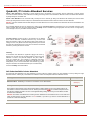
QuadroE1/T1’s Auto Attendant Services ............................................................................ 78
67H
14H
Call Codes Available in Auto Attendant .......................................................................................... 78
68H
145H
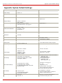
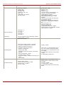
Appendix: System Default Settings .................................................................................... 79
69H
146H
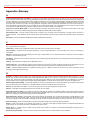
Appendix: Glossary............................................................................................................. 81
70H
147H
Appendix: Software License Agreement ............................................................................. 86
71H
QuadroE1/T1 (SW Version 3.0.x)
148H
QuadroE1/T1 Manual II: Administrator's Guide
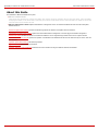
About this Administrator's Guide
About this Guide
The QuadroE1/T1 Manual is divided into two parts:
• Manual-I: Installation Guide
gives step-by-step instructions to provision the Quadro and configure the phone extension with the Epygi SIP Server. After successfully
configuring the Quadro, a user will be able to make SIP phone calls to remote Quadro devices, make local calls to the PSTN and access the
Internet from devices connected to the LAN.
• Manual-II: Administrator's Guide explains all QuadroE1/T1 management menus. It includes the available call codes and a list of all System
Default Values, too
Quadro’s Graphical User Interface introduces the Quadro's graphical user interface and explains all recurrent buttons.
H72149U
UH
Administrator’s Graphical User Interface explains each of the Administrator's management on the main page of the Quadro management.
U
U
Quadro’s Call Codes describes the Quadro’s call codes that enable the user to navigate through Quadro’s services from a phone handset.
150HU
U
Quadro’s Auto Attendant Services explains the operation of the Quadro's auto attendant and lists the call codes that may be used to enter the
auto attendant.
U
Appendix: System Default Settings lists all factory defaults.
15HU
U
Appendix: Glossary defines some technical terms.
Appendix: Software License Agreement includes the terms and conditions of using the Quadro's hardware and software.
QuadroE1/T1; (SW Version 3.0.x)
4
QuadroE1/T1 Manual II: Administrator's Guide
Quadro’s Graphical User Interface
Quadro’s Graphical User Interface
Administrator’s Main Page
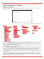
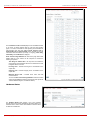
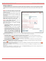
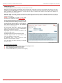
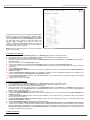
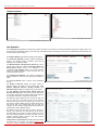
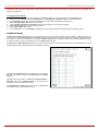
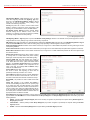
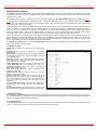
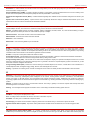
After logging in as an administrator, the page Quadro Management is displayed. Here the administrator may access the following settings and
perform the following actions:
Fig. II-1: Quadro Administrator’s page
System Menu
• System Configuration Wizard
152H
153H
•
Internet Configuration
Wizard
•
154H
•
•
•
•
•
•
•
•
•
•
•
StatusIP Routing
Configuration
15H
156H
Configuration Management
157H
Update Configuration
158H
Events
159H
Time/Date Settings
160H
Mail Settings
16H
Firmware Update
162H
Networking Tools
163H
Diagnostics
Telephony Menu
• Call Statistics
168H
169H
•
•
•
•
•
•
•
•
•
•
•
SIP Settings
LAN Services Menu
• DNS Settings
Users Menu
• User Management
1) Change Admin Password
182H
190H
•
183H
170H
H323 Settings
DHCP Settings for the LAN
Interface
19H
17H
RTP Settings
172H
NAT Traversal Settings
173H
Line Settings
174H
E1/T1 Settings
175H
Gain Control
Internet Uplink Menu
• PPP Dial Settings
Registration Form
192H
185H
•
•
•
ISP Authentication Settings
(in menu tree only)
186H
Firewall and NAT
187H
Logout
193H
Filtering Rules
18H
176H
Call Routing
17H
VoIP Carrier Wizard
178H
RADIUS Client Settings
179H
Dial Plan Settings
180H
164H
Automatic Provisioning
165H
Features
16H
Upload Language Pack
167H
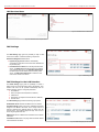
The functional button Renew Wan IP Address appears on the administrator’s main Quadro Management page if the Quadro device acts as a
DHCP client. The Renew WAN IP Address button is used to get a new WAN IP address for example when the Quadro moves to another network.
The functional button Establish Your Internet Connection Now respectively Terminate Your Internet Connection Now appears on the Quadro
Management page if PPPoE is used as the WAN interface protocol.
The button Please Check Your Pending Events will be displayed on the administrator Main Menu page if any new system events exist. The link
leads to the Events page that can also be accessed from the System menu.
The list of Users currently logged into the system is seen in the lower right corner of the Administrator's Main Menu. Information about the IP
address of a user, the username used to log in and the time until the next automatically logout is provided herein. The idle session timeout is to 20
minutes. If no action is performed during that time, user will be automatically moved to the Login page and will be requested to login again.
The link Refresh in appears in the lower right corner beside the field displaying the number of seconds until the next refresh. It is used to perform a
manual reload of the page. If a page with a Refresh counter is left open, the session time-out counter will be updated periodically and the logout
timeout will never expire.
The current version of the Quadro's firmware and of its boot loader is shown in the lower right corner of the administrator’s main menu, followed by
the list of users currently logged into the system. Information about IP addresses users accessed Quadro from, the username of the logged-in user
and the time until the next automatic logout is provided here. The idle session timeout is set to 20 minutes. If no action is done during that time, the
user automatically will be moved to the login page and will be requested to login again.
QuadroE1/T1; (SW Version 3.0.x)
5
QuadroE1/T1 Manual II: Administrator's Guide
Quadro's Graphical Interface
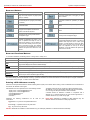
Recurrent Buttons
Button
Description
Button
Description
This button leads back to the previous
page of a fixed sequence of pages (used
mainly in wizards).
This button leads back to the page you have
been on before.
This button leads onward to the next page
of a fixed sequence of pages (used mainly
in wizards).
This button confirms an operation you started
before.
This button discards the latest, not yet
confirmed entries.
This button confirms an operation you chose
before.
This is the last button of a fixed sequence
of pages that completes and saves the
entries of the whole sequence.
This button discards an operation you chose
before.
This button opens the help page
belonging to the currently active Quadro
management page.
This button saves the settings modified on the
currently active management page.
This button opens a window where the last
inserted IP addresses are listed. It is a
kind of clipboard that helps the user to
make quick selection of an IP address in
case it has been already used in the past,
thus to avoid typing it again. The clipboard
can hold up to 10 IP addresses, a new IP
address will replace the oldest one from
the list.
This button opens a window where the last
inserted SIP addresses are listed. It is a kind of
clipboard that helps the user to make quick
selection of a SIP address in case it has been
already used in the past, thus to avoid typing it
again. The clipboard can hold up to 10 SIP
addresses, a new SIP address will replace the
oldest one from the list.
Recurrent Functional Buttons
In connection with tables, the following buttons - among others - usually occur:
Functional Button
Description
Add
Allows adding a new record to the displayed table. A new page will be displayed to enter any new settings.
Edit
Allows modifying the settings of the record selected by its checkbox. Normally only one record may be selected. A new
page will be displayed to enter the modified settings.
Delete
Deletes the selected entry(s) of a table. A warning message will demand a confirmation before deleting an existing entry.
Select All
Selects all table entry(s)for example for further deletion.
Inverse Selection
Inverses an existing selection of table entry(s). If no entries are selected, clicking the button will select all records.
Refresh in...
May occur in the upper right corner of a page. It displays the number of seconds remaining until the next refresh of the page
and it may be used to reload the page manually.
Most of the tables offer the option to sort the entries in ascending or descending order by clicking the headings of the columns. A small arrow beside
the column heading will show the direction of sorting - upward or downward. The entries of the table can be selected by the assigned checkboxes one at a time, for the most part - in order to edit or delete them.
Entering a SIP Addresses correctly
Calls over IP are implemented based on Session Initiating Protocol (SIP) on the Quadro. When making a call to a destination that is somewhere on
the Internet, SIP address must be given.
The display name and the port number are optional parameters in the
SIP address. If a port is not specified, 5060 will be set up as the default
one. The range of valid ports is between 1024 and 65536.
SIP addresses have to be specified in one of the following formats:
“display name” <username@ipaddress:port>
“display name” <username@ipaddress>
username@ipaddress:port
username@ipaddress
username
Particularly the
convenience:
following
combinations
can
A flexible structure of wildcards is allowed. In comparison with a
wildcard, the “?” character stands for only one unknown digit and the “*”
character stands for any number of any digits.
be
used
for
your
Please Note: Wildcards are available for caller addresses only. No
wildcard characters are allowed for called party addresses.
• *@ipaddress - any user from the specified SIP server
• username@* - a specified user from any SIP server
• *@* - any user from any SIP server
Attention: Wildcards are available for caller addresses only (for called party addresses no wildcard characters are allowed).
QuadroE1/T1; (SW Version 3.0.x)
6
QuadroE1/T1 Manual II: Administrator's Guide
Administrator's Graphical User Interface
Administrator’s Menus
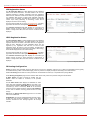
System Menu
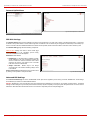
Fig. II-1: System Menu in Dynamo theme
Fig. II-2: System Menu in Plain theme
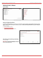
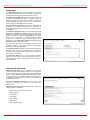
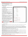
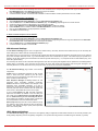
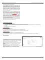
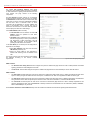
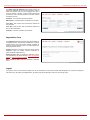
System Configuration Wizard
The System Configuration Wizard is the helpful tool for the administrator to define the Quadro’s Local Area Network settings and to specify
regional configuration settings to make Quadro operational in its LAN. The System Configuration Wizard MUST be run upon Quadro's first
startup to make sure that it works properly in its network environment. The Wizard allows navigating through the following basic configuration
parameters and settings:
•
•
•
System Configuration (see below)
DHCP Settings for the LAN Interface
194H
Regional Settings and Preferences (see below)
DHCP Settings for LAN are described in the chapters below
while LAN configuration and regional settings will be described
in the current chapter.
Please Note: It is strongly recommended to leave the
factory default settings if their meanings are not fully
clear to the administrating person.
Fig. II-3: System Configuration Wizard - Start page
QuadroE1/T1; (SW Version 3.0.x)
7
QuadroE1/T1 Manual II: Administrator's Guide
Administrator's Graphical User Interface
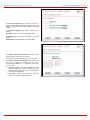
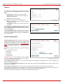
The System Configuration page contains the host name, IP
address and Subnet Mask information about the Quadro LAN
interface. These settings make Quadro available to the internal
network.
The System Configuration page offers the following input
options:
Host Name requires a host name for the Quadro device.
IP Address requires the Quadro host address for the LAN
interface.
Subnet Mask requires the Quadro hosts’ Subnet Mask.
Fig. II-4: System Configuration Wizard - System Configuration page
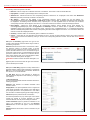
The Regional Settings and Preferences are used to select
settings specific to the location of the Quadro.
This is important for the functionality of the voice subsystem.
The Regional Settings and Preferences page has two drop
down lists to select the Location (country) and a
corresponding Timezone and a manipulation radio button
group to choose:
•
•
System Language – selection is available only when
custom Language Pack has been uploaded and is used
to enable custom language for system voice messages or
turn back to default (English).
GUI Theme - selection used to select the GUI theme
style of the web based configuration pages.
QuadroE1/T1; (SW Version 3.0.x)
Fig. II-5: System Configuration Wizard - Regional Settings page
8
QuadroE1/T1 Manual II: Administrator's Guide
Administrator's Graphical User Interface
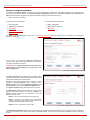
Internet Configuration Wizard
The Internet Configuration Wizard is the helpful tool for the administrator to configure the WAN interface settings and to adjust Quadro’s
connectivity with an external network. The Internet Configuration Wizard MUST be run if it is desired for Quadro to be connected to the
Internet. The Wizard allows navigating through the following basic configuration parameters and settings:
•
Uplink configuration (see below)
For WAN Interface protocol Ethernet:
For WAN Interface protocol PPPoE:
•
•
•
•
•
•
•
•
PPP Configuration
WAN Interface Configuration
DNS Settings
195H
WAN IP Configuration
WAN Interface Configuration
DNS Settings
198H
ISP Authentication Settings
196H
PPP Dial Settings
197H
The Switch to Auto Provisioning link moves you to the Automatic Provisioning page where Quadro can be configured by the automatically
provisioning mechanism.
19H
All the settings of the Internet Configuration Wizard are
described in the chapters below except those for the IP settings,
which will be described in this chapter.
Please Note: It is strongly recommended to leave the factory
default settings if their meanings are not fully clear to the
administrating person.
Fig. II-6: Internet Configuration Wizard - Start page
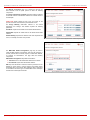
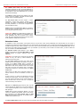
The Uplink Configuration page allows to select the Quadro‘s WAN
interface connection type and its bandwidth settings. These settings
make Quadro available to the external network.
Depending on the Uplink Interface Protocol selection, the page
following the Uplink Configuration page is different. Thus if
PPPoE is selected, the next page will be PPP Configuration, while
selecting Ethernet will bring up the WAN IP Configuration page.
The Uplink Configuration page offers the following components:
The WAN Interface Protocol radio buttons are used to choose
between Point-to-Point Protocol over Ethernet (PPPoE) and
Ethernet. Selection depends on the requirements of the ISP
(Internet Service Provider).
PPPoE - turns on the PPP over Ethernet connection type.
PPPoA – selection is only present when corresponding
interfaces are present on the Quadro and are used to turn on
the PPP over ADSL/G.SHDSL connection type.
Ethernet - turns on the Ethernet connection type.
Fig. II-7: Internet Configuration Wizard - Uplink Configuration page
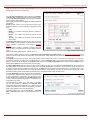
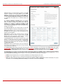
The WAN Interface Bandwidth settings allow the specification of the upstream and downstream speeds in kbit/s, helping to assure the quality of IP
calls. An IP call looses the voice quality if there will be no available bandwidth. In case of reaching the borders of bandwidth, another IP call will be
declined.
QuadroE1/T1; (SW Version 3.0.x)
9
QuadroE1/T1 Manual II: Administrator's Guide
Administrator's Graphical User Interface
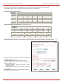
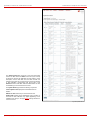
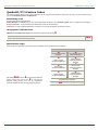
The bandwidth provided by the ISP has to be specified in the text fields Upstream Speed and Downstream Speed. The default entry in both fields
is 10000, the maximum bandwidth of a 10 MB Ethernet. But most providers offer a smaller bandwidth than these 10000 kbit/s.
The bandwidth required by an IP call depends on the codecs used and is listed in the tables below:
Required Bandwidth for Standard Packets:
Packet Size in
msec.
G.711u/G.711a
G.726-16
Needed bandwidth in kbit/s using the Codecs:
G.726-24
G.726-32
G.726-40
G.729a
10
105
58
66
73
81
50
20
84
37
45
52
60
29
30
77
30
38
45
53
22
40
73
26
34
42
50
18
50
71
24
32
40
48
16
60
70
23
30
38
46
15
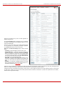
Required Bandwidth for Encrypted Packets (in the case a VPN is used):
Packet Size in
msec.
G.711u/G.711a
G.726-16
Needed bandwidth in kbit/s using the Codecs:
G.726-24
G.726-32
G.726-40
G.729a
10
148
98
105
117
123
92
20
105
59
65
74
80
49
30
91
43
52
60
66
35
40
84
37
45
53
61
29
50
80
33
41
48
56
25
60
77
30
37
46
53
22
The Min Data Rate text field requires the amount of upstream bandwidth that ought to remain for data applications even if voice applications use the
entire available upstream bandwidth. The value selected here needs to be smaller than the upstream bandwidth and is measured in kbit/s.
If PPPoE is selected as the WAN Interface Protocol then the PPP
Configuration page is opened next.
The PPP Configuration page offers the following components:
IP Address Assignment radio buttons are used to configure the IP
address for the Quadro device:
•
•
Dynamic IP Address - switches to the dynamic IP address
assignment mechanism.
Fixed IP Address - switches to the fixed IP address assignment
mechanism.
Fixed IP Address requires entering the user defined IP address for
the Quadro device on the WAN interface.
Fig. II-8: Internet Configuration Wizard – PPP/PPtP Configuration page
QuadroE1/T1; (SW Version 3.0.x)
10
QuadroE1/T1 Manual II: Administrator's Guide
Administrator's Graphical User Interface
The WAN IP Configuration page only is displayed if Ethernet has
been selected to be the uplink protocol. It offers the following
components:
The Assign automatically via DHCP radio-button selection switches
to automatic retrieval of the WAN IP address from a DHCP server at
the ISP/uplink.
Please Note: DHCP referred to here is the one running on the
provider’s side and not the Quadro’s personal DHCP server.
The Assign Manually radio-button switches to the manual
adjustment of IP settings. This selection requests the following
parameters:
IP Address requires the IP address for the Quadro WAN interface.
Subnet Mask requires the subnet mask for the Quadro device WAN
interface.
Default Gateway requires the IP address of the router all packets are
sent to, for example, the router of the provider.
Fig. II-9: Internet Configuration Wizard - WAN IP Configuration page
The WAN MAC Address Configuration page may be used to
modify the MAC address of the Quadro. This might be necessary, if
the ISP (Internet Service Provider) requires a certain MAC address,
for example, for authentication. The page offers the following
components:
MAC Address Assignment manipulation radio-buttons:
•
•
This Device turns to the default MAC address of the Quadro.
User Defined requires user defined MAC Address.
MTU drop down list allows to select the maximum packet size on the
Ethernet (in bytes). MTU is used to fragment the packets before
transmitting them to the network. MTU preferred value is dependent
on the Ethernet connection type. The default MTU size is 1500 Bytes
for Ethernet and 1400 Bytes for PPPoE.
Fig. II-10: Internet Configuration Wizard - WAN MAC Address Configuration page
QuadroE1/T1; (SW Version 3.0.x)
11
QuadroE1/T1 Manual II: Administrator's Guide
Administrator's Graphical User Interface
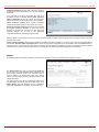
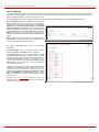
Status
The system status window displays non-editable tables providing extensive status information about Quadro: General Information, Network Status,
Lines Status, Memory Status, Hardware Status, SIP Registration Status and H323 Registration Status. The links on this page lead to device Transfer
Statistics, user mailboxes and supplementary services configuration pages.
20H
20H
203H
204H
205H
201H
206H
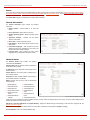
The System Status page has several tables providing system information.
General Information
The General Information page includes the following
information:
•
•
•
•
•
•
•
•
Uptime duration - Period Quadro is on since last
reboot.
Device Hostname - Quadro device host name.
Quadro Operating System - Quadro operating system
version.
Application Software - Software and file system
versions of the Quadro.
Boot Loader - Quadro boot loader version.
DSP Software - Quadro DSP software version and the
date of build.
Preinstalled Languages – field is present only when
multiple languages are preinstalled on the device and
indicates the system default languages.
Language Pack – field is present only when custom
language pack is uploaded and indicates its version.
Fig. II-11: Quadro Status - General Information page
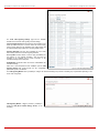
Network Status
The Network Status page includes the following
information about Interfaces:
Interface Name lists the Network interfaces available on
the Quadro (LAN and WAN).
IP Address lists the IP addresses corresponding to each
network interface.
Subnet Mask lists the subnet masks corresponding to
each network interface.
Properties lists either the MAC address corresponding to
each network interface on the Quadro.
Monitor includes links to survey LAN and WAN traffic
correspondingly.
•
•
•
•
•
•
Received Drop Errors
•
•
•
•
Received Overrun
Errors
•
Received MultiCast
Packets
•
Received Bytes
Received Packets
Received Errors
Transmitted Bytes
Transmitted Packets
Transmitted Errors
Transmitted Drop
Errors
Transmitted Carrier
Errors
Fig. II-12: Quadro Status Network Status page
Transmitted Collisions
When opening the corresponding interface statistics window, no traffic values are displayed at first. Then every one minute, traffic statistics will be
updated. The tables serve as a kind of counter.
DNS Server, Alternative DNS Server and Default Gateway - displays the Quadro settings corresponding to what has been configured with the
System Configuration Wizard.
207H
Services (NTP Server and Client, DHCP Server and Client, DNS, Firewall, NAT, PPP) statuses: stopped or running.
Transfer Statistics - link to the Transfer Statistics page.
QuadroE1/T1; (SW Version 3.0.x)
12
QuadroE1/T1 Manual II: Administrator's Guide
Administrator's Graphical User Interface
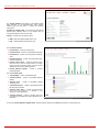
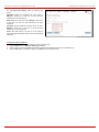
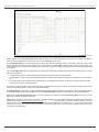
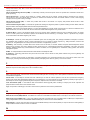
The Transfer Statistics page allows a user-defined statistic
table depending on the transmit/receive value (criteria),
interface type and time period. It contains the following
components:
Time Range of statistic table - the drop down list includes the
period(in days) statistics data is to be collected and the
corresponding diagram charts are to be built.
Interface - the drop-down list offer the values:
•
•
WAN - Wide Area Network (WAN) events only
LAN - Local Area Network (LAN) events only
Fig. II-13: Transfer Statistics page
The area Receive Values:
•
•
•
•
•
•
Receive Bytes - number of received bytes
Receive Packets - number of received Ethernet packets
Receive Errors - number of received packets containing
errors
Receive Drop Errors - number of received packets that
have been discarded
Receive Overrun Errors - number of received overrun
errors that occur when the receive buffer is not large
enough to hold all incoming packets. This error mostly
appears because of a slow receiving system.
Receive MultiCast Packets - number of received
broadcast packets
The area Transmit Values:
•
•
•
•
•
•
Transmit Bytes - number of transmitted bytes
Transmit Packets - number of transmitted Ethernet
packets
Transmit Errors - number of transmitted packets
containing errors
Transmit Drop Errors - number of transmitted packets
that have been discarded
Transmit Carrier Errors - number of transmit carrier
errors that occur because of a defective or lost
connection on the Ethernet link
Transmit Collisions - number of transfer errors that
occurred during a simultaneous packet transmission from
both sides
Fig. II-14: Transfer Statistics Diagram Chart
To show the Transfer Statistics Diagram Charts, select the desired criteria and click Save to generate the corresponding chart.
QuadroE1/T1; (SW Version 3.0.x)
13
QuadroE1/T1 Manual II: Administrator's Guide
Administrator's Graphical User Interface
Lines Status
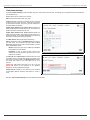
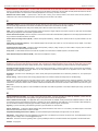
The page Quadro Status - Lines Status shows the current status of the extension and E1/T1 trunk. Since only one line information is displayed at a
time, the Phone1 and E1/T1 Trunk buttons serve to navigate through the lines information.
The Lines Status table displayed for Phone1 lines includes a group of
static and dynamic parameters. Static parameters are displayed
always, while dynamic parameters only appear whenever an event
takes place on the extension.
Static Parameters:
Extension - the extension number of the selected telephone line
Display Name – the corresponding name
Phone State - On hook or off hook
Number of Active Calls – that are currently present on the phone.
Dynamic Parameters:
Call State – the current state of the extension (in call, waiting,
busy, call out, ring in etc.)
Caller Party – this parameter appears whenever a call is received
and indicates the caller extension, the IP address or a phone
number depending on the call type
Called Party – this parameter appears whenever a call is placed
and indicates the destination extension, the IP address or a phone
number depending on the call type
Call Type – shows whether the call is Internal or External and
whether it is a PSTN, PBX or IP Call
Call Start Time – call start date and time
Call Duration – current call duration
RX Codec shows the codec used to encrypt the incoming packets.
TX Codec shows the codec used to encrypt the outgoing packets.
If RX and TX codecs are the same, one Codec field will be
displayed instead.
QuadroE1/T1; (SW Version 3.0.x)
Fig. II-15: Line Status – Line Status page upon established call
14
QuadroE1/T1 Manual II: Administrator's Guide
Administrator's Graphical User Interface
The Line Status for E1/T1 Trunk displays the list of available timeslots
(in E1 mode, 30 active timeslots both for CAS and CCS signaling
types; in T1 mode, 24 timeslots for CAS signaling and 23 timeslots for
CSS signaling type) and their settings (Route Incoming Call to,
Allowed Call Type and Timeslot State). When Timeslot is in the call,
information about call direction (incoming or outgoing), Caller Party,
Called Party and Call Duration is displayed.
E1/T1 Channel Usage Statistics link refers to the page where traffic
statistic table for E1/T1 channel can be composed. It contains the
following components:
Time Range of statistic table - the drop down list includes the
periods (days) for that statistics data is to be collected and for that
a diagram chart is to be built.
Incoming Calls – indicates incoming E1/T1 call statistics in the
output chart.
Outgoing Calls - indicates outgoing E1/T1 call statistics in the
output chart.
Maximum Active Calls – indicates E1/T1 active calls with
maximal duration.
To show the E1/T1 Channel Usage Statistics select the desired
criteria and click Show to build the corresponding chart (looks like
Transmit Statistics Diagram, see Network Status).
Fig. II-16: Line Status – Line Status page for E1/T1 trunk
Hardware Status
The Hardware Status table displays a list of the hardware
devices present and currently available on the Quadro board. The
hardware device version number and additional comments about
its state are indicated here.
QuadroE1/T1; (SW Version 3.0.x)
Fig. II-17: Hardware Status page
15
QuadroE1/T1 Manual II: Administrator's Guide
Administrator's Graphical User Interface
SIP Registration Status
The SIP registration Status is a table displaying the SIP registration
status of the Quadro extensions. The table contains a list of all the
registered extensions of Quadro, information about SIP registration
states for them, addresses of SIP servers where they are registered (if
so), registration date and time, as well as SIP registration names. By
clicking on the row heading, the table will be sorted by the selected
column. Upon sorting (ascending or descending), arrows will be
displayed next to the column heading.
The links inside the table link you to the User Management – Edit Entry
page where the extension’s SIP registration settings may be altered.
208H
The Detected Connection Type field displays the connection type
Quadro currently is acting in (direct connection or behind NAT). If
Quadro is acting behind NAT, the NAT machine IP address is also
displayed.
Fig. II-18: SIP Registration Status page
H323 Registration Status
The SIP registration Status is a table displaying the H.323 registration
status of the Quadro extensions. The table contains a list of all the
registered extensions of Quadro, information about H.323 registration
states for them, addresses of H.323 gatekeepers where they are
registered (if so), registration date and time, as well as H.323
registration names. By clicking on the row heading, the table will be
sorted by the selected column. Upon sorting (ascending or descending),
arrows will be displayed next to the column heading.
The links inside the table link you to the User Management – Edit Entry
page where the extension’s H.323 registration settings may be altered.
209H
The Detected Connection Type field displays the connection type
Quadro currently is acting in (direct connection or behind NAT). If
Quadro is acting behind NAT, the NAT machine IP address is also
displayed.
Fig. II-19: H.323 Registration Status page
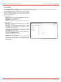
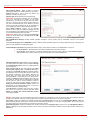
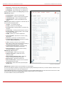
IP Routing Configuration
Routing is used to relay information across the Internet from a source to a destination. Along the way, at least one intermediate node is typically
encountered. Routing is often confused with bridging, which may seem to accomplish precisely the same thing to the casual observer.
Quadro’s IP Routing service allows to route IP packets from one destination to another (or to a specified router) through Quadro.
The IP Routing Configuration page is used to make IP Static and IP Policy routes for IP packets routing and has two tables.
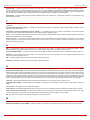
IP Static Routes are used to forward IP packets from the
Network, where the Quadro is connected, to the specified
destination.
The IP Static Routes table displays all established IP static
routes with their parameters: Target State for the state of the
route (enabled or disabled), Actual State for the state of the route
connection (up, down or erroneous), Route To for the subnet
where the incoming packets should be routed and Via IP Address
for the router IP address incoming packets should be routed
through.
Add opens the Add IP Static Route page where a new static
route can be established.
Enable/Disable are used to activate/deactivate selected route(s).
At least one route should be selected in order to use these
functions, otherwise the error message appears: “No record(s)
selected.”
Fig. II-20: IP Static Routing table
QuadroE1/T1; (SW Version 3.0.x)
16
QuadroE1/T1 Manual II: Administrator's Guide
Administrator's Graphical User Interface
The page Add IP Static Route offers the following components:
Route To requires the IP address and subnet mask of the
destination the IP packet ought to be forwarded to.
Via IP address requires the IP address of the subsequent router
for IP packet forwarding to the specified destination.
Attention: The rule with the longest subnet (smallest IP range)
will take effect when having two or more IP Static routing rules
with the coinciding subnets.
Fig. II-21: Add IP Static Routing page
IP Policy Routes allow IP packets forwarding to the specified
router depending on the source IP address as well as defining the
priority for the current routing rule.
The IP Policy Routes table displays all specified IP policy routes
with their parameters: Target State for the state of the route
(enabled or disabled), Actual State for the state of the route
connection (up, down or erroneous), Priority for the route priority,
Route From for the subnet, routed packets come from and Via IP
Address for the router IP address incoming packets should be
routed through.
Add opens the page Add IP Policy Route to establish a new
policy route.
Enable and Disable are used to activate or to deactivate the
selected route(s).
Raise and Lower Priority are used to increase or to decrease the
priority of the selected policy route(s) by one. At least one route
should be selected to use these functions, otherwise the error
message appears: “No record(s) selected.”
Fig. II-22: IP Policy Routing table
The page Add IP Policy Route offers the following input options:
Priority requires a numeric value (from 1 to 252) to define the
priority of the routing rule. The lower the number, the sooner the
routing rule will take effect (higher priority).
From requires the packet source IP address and subnet mask of
the specified destination to match with the rule.
Via IP address requires the IP address of the subsequent router
for IP packet forwarding.
Fig. II-23: Add IP Policy Route page
The Enable and Disable functional buttons are used to activate or to deactivate the selected route(s). At least one route should be selected to use
these functions, otherwise the error message appears: “No record(s) selected.”
To Add an IP Static Route
1.
2.
3.
4.
5.
Select the IP Static Routes link on the Routing Configuration page.
Press the Add button on the IP Static Routes page. The Add Entry page will appear in the browser window.
Enter the destination IP address and subnet mask in the Route To text fields. Use the IP-Clip button to select a previously entered IP address.
Enter the router IP address into the Via IP Address text fields.
Press the Save button to make the static route with these settings.
To Add an IP Policy Route
1.
2.
3.
4.
5.
6.
Select the IP Policy Routes link on the Routing Configuration page.
Press the Add button on the IP Policy Routes page. The Add Entry page will appear in the browser window.
Specify the policy routing rule priority in the Priority text field.
Enter the packet source IP address and subnet mask in the From text fields. Use the IP-Clip button to select a previously entered IP address.
Enter the router IP address into the Via IP Address To text fields.
Press the Save button to make the policy route with these settings.
QuadroE1/T1; (SW Version 3.0.x)
17
QuadroE1/T1 Manual II: Administrator's Guide
Administrator's Graphical User Interface
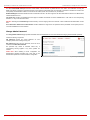
Configuration Management
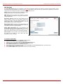
The Configuration Management assists the administrator to manage the system configuration settings and voice data, i.e., to backup and
download the settings to the PC and then to upload and restore them back to the Quadro. Additionally this page gives a possibility to restore the
factory default configuration settings.
The Backup & Download all config & voice data link
generates a backup file with all configuration settings and
user uploaded greeting messages and opens a file chooser
window for immediate download to the user PC.
Attention: Configuration and voice data cannot be backed
up if the size of voice data is too large. In this case, to be
able to backup configuration and voice data on the Quadro,
please remove some user defined system messages (by
restoring the default ones, see chapter Administrators Login
at Feature Codes), or remove some extensions from the
User Management table.
210H
Fig. II-24: Configuration Management page
The Upload & Restore all config & voice data link opens a page with the Browse button, (which opens a file chooser to select a backed-up file)
and a Configuration to Upload field requiring the file path to upload and to restore it immediately. Pressing Save will restore the selected backup
file, and delete all current user defined greetings and replace configuration settings.
The Use Default functional button resets all configuration settings and restores the board’s factory default configuration. By restoring the default
configuration you will replace your current one and reboot the device. You will not be automatically redirected to the GUI start page. After the
successful reboot you will need to enter into the management and login again to access the Quadro’s configuration. A warning message will ask you
to confirm your selection before restoring the default configuration.
Please Note: Unlike the factory default settings restore procedure initialized from the Reset button on the Quadro board, this link will keep the
following data:
• Call Statistics
• Transfer Statistics
• System Events
• Feature Keys
• Device Registration state
QuadroE1/T1; (SW Version 3.0.x)
18
QuadroE1/T1 Manual II: Administrator's Guide
Administrator's Graphical User Interface
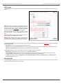
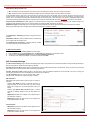
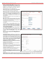
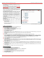
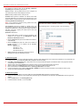
Update Configuration
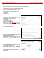
The Update Configuration allows to automatically or interactively update Quadro’s configuration, as well as to download a legible and editable
configuration file, make necessary changes and upload it back to the system. This particularly allows to use parts of the configuration of one Quadro
on another Quadro with some changes done prior to uploading the new configuration. Service is mainly used by Quadro reseller, distributor, ISP or
carrier.
Attention: It is strongly recommended to consult with technical
support center before making changes on this page. Incorrect
settings here may corrupt current configuration. Page consists of
the following components:
Server and Server Port text fields require IP address or Host
name and the port number of the server configuration will be
downloaded from.
Update Method drop down list indicates the connection type
used to download the configuration (ftp, tftp, http or https).
Enable Version Check checkbox selection enabled version
verification before configuration is being downloaded.
Attention: Disabling Enable Version Check checkbox may
cause incompatibility problems on the device.
Update Interval Selection manipulation radio-button group is
used to select the frequency of configuration check/update
performed on the Quadro:
•
•
•
Check/Update at boot time – with this option, new
available configuration will be checked/updated each time
after Quadro boots.
Check/Update manually – with this option, configuration
check/upload will be performed only by manual selection.
Check/Update time/date scheduled – with this option new
available configuration will be checked/updated periodically
dependent on the selected time and/or weekday. This
selection enables Time Based and Weekday Based
checkboxes. Selecting one or both of them allows to define
the time and the weekday, when configuration check/update
will be automatically performed.
Fig. II-25: Upload Configuration page
Update Policy Selection manipulation radio-button group is used to select the operation performed on the selected:
•
Check only for update – with this option, system will only perform checking of the availability of new suitable configuration and will log
corresponding event in the Events table (depending on configuration in Events Settings).
21H
•
Check and update immediately - with this option, system will check the availability and correspondingly update the new configuration and will
log corresponding event in the Events table (depending on configuration in Events Settings).
21H
•
Check and update immediately without any feedback - with this option, system will check the availability and correspondingly update the
new configuration but will not log any events on this.
Check now for new update functional button performs manual checking of the availability of new suitable configuration and logs corresponding
event in the Events table (depending on configuration in Events Settings).
213H
Update now functional button performs manual checking and update of the availability new configuration and logs corresponding event in the Events
table (depending on configuration in Events Settings).
214H
Update now without feedback functional button performs manual checking and update of the availability new configuration and does not log any
events on this.
Download current configuration in a legible format link refers to the Configuration Summary page where necessary configuration part or a
complete configuration can be defined and downloaded or viewed.
QuadroE1/T1; (SW Version 3.0.x)
19
QuadroE1/T1 Manual II: Administrator's Guide
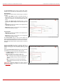
Administrator's Graphical User Interface
Configuration Summary page is used to define the necessary
configuration part and to download it to PC or to view it directly in
the browser.
In the text field on this page configuration part need to be
downloaded should be specified. Pressing Start generate a
legible configuration file will start parsing the configuration
structure of the device. Progress will be seen in the area below.
Cancel generation process button appears immediately
configuration generation procedure starts and is used to stop it.
Download generated configuration button becomes available
once legible configuration generation is over and is used to
download the generated file to the PC in the plain text format.
Necessary changed can be done in the downloaded
configuration file and then uploaded back to the system.
Fig. II-26: Configuration Summary page
Attention: Make sure the changes you have done in the downloaded legible configuration file are valid and will not corrupt the system when being
uploaded back to device.
View generated configuration button becomes available once legible configuration generation is over and is used to view the generated file directly
in the browser.Upload a legible configuration file link refers to the page where configuration file can be uploaded in text format. Browse button in
the opened page is used to browse the certain legible configuration file to be uploaded and updated to the system. Configuration files to be uploaded
should be in the *.txt format, otherwise system error occurs. Configuration file upload progress will be displayed in the area below.
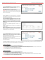
Events
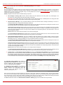
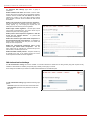
The Events page shows two tables and displays all system events that have occurred in one table and event settings in the other.
The System Events page may be accessed with Events link
from the main menu. It lists information about system events that
have occurred on Quadro. When a new event takes place, a
record is added to the System Event table and a warning
“Please check your pending events!” appears at the bottom of all
management pages.
The system events and the warning message are visible only for
the administrator. The warning link, (which leads directly to the
System Events page) will disappear from the management
pages if the administrator has marked all new events as read.
Fig. II-27: Event Warning on the Main Menu page
QuadroE1/T1; (SW Version 3.0.x)
20
QuadroE1/T1 Manual II: Administrator's Guide
Administrator's Graphical User Interface
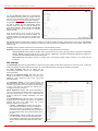
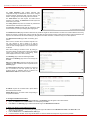
The System Events table is the list of new and read system
events. The table shows the Status of the event (new or read)
as well as the name of the application the event refers to, event
description, and the date when the event was received. For
example, if the event has occurred due to incorrect mail sending
or SIP registration, corresponding links will be seen in the
Reference column of the table. There the administrator can view
the detailed log for the event that has occurred.
The System Events page offers the following components:
Current System Time displays the local date and time on
Quadro.
Mark all as read marks newly occurred events as read.
Disable LED switches off the LED flashing (if any do flash) on
the board. A LED notification may appear (depending on the
notification type given) in the page Events settings whenever a
new event occurs.
215H
Fig. II-28: System Events list
QuadroE1/T1; (SW Version 3.0.x)
21
QuadroE1/T1 Manual II: Administrator's Guide
Administrator's Graphical User Interface
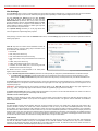
Numerous circumstances may cause a certain application on
Quadro to flag an event.
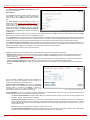
The page Event Settings lists all possible events on the Quadro
and allows controlling the way of notification (action), if one of
those events takes place.
Each entry in the events’ table has its checkbox assigned to the
row. By selecting the corresponding checkboxes, operations
such as Edit may be done for one or more events.
Edit opens the Edit Event Settings page to modify the event
action.
Do Nothing - Nothing will happen when the event occurs.
Display Notification - A notification link will be displayed on
the bottom of all pages and a record is added into the Events
table. The notification is executed as the link “Please Check
you pending events!” that leads to the page System Events.
This action also will take place if Flash LED or Send Mail has
been selected, even if not selected explicitly.
Flash LED - The second LED (yellow) will be blinking once a
second and a notification will be displayed on the bottom of all
pages. For some events the LED will start flashing after a
delay.
Send Mail - An e-mail with a notification about the new event
and an event description in the mail body will be sent to the email address specified in the Mail Settings page.
216H
Fig. II-29: Event Configuration Settings page
Actions that are not allowed for the selected event (like mail notification if the PPP link is down or the mail server has been misconfigured) are
hidden. For multiple events editing, actions that do not fit at least to one of the selected events will be hidden.
If Quadro cannot get an IP address from the DHCP or PPP servers, or cannot register an extension on the SIP or Routing servers, or cannot reach
an NTP server, it raises only one event for the entire period the action has failed, but continues to try. When the required action is successful,,
Quadro raises an appropriate message.
QuadroE1/T1; (SW Version 3.0.x)
22
QuadroE1/T1 Manual II: Administrator's Guide
Administrator's Graphical User Interface
The page Edit Event Settings offers the following input
options:
Application displays the application the event refers to.
Multiple is shown here, if more than one event has been
selected for the action assignment.
Name displays the name of the event. Multiple is shown here,
if more than one event has been selected for the action
assignment.
Description displays additional information about the event.
Multiple is shown here, if more than one event has been
selected for the action assignment.
Action offers radio buttons to choose one of the actions to
notify the Quadro administrator whenever the selected event(s)
takes place.
Fig. II-30: Edit Event Settings page
To Assign an Action to the Event
1.
2.
3.
4.
Select the checkbox of one or more events to assign an action to them.
Press the Edit button. The Edit Event Settings page appears.
Select an action type from the Action radio buttons to notify the administrator about the event in the desired way.
Press the Save button to submit the changes or use Back to abort the selected action.
QuadroE1/T1; (SW Version 3.0.x)
23
QuadroE1/T1 Manual II: Administrator's Guide
Administrator's Graphical User Interface
Time/Date Settings
The Time and Date Settings provide information about the current system time and date. The settings may be updated through the international
time and date servers.
Time is used to set the local time (hour, minute).
Date is used to set the date (month, day, year).
Timezone provides a selection of world time zones and is used
to select the local country time zone. Timezones are specified
by GMT (Greenwich Mean Time) and by specific timezones for
the United States and Canada.
Enable Simple Network Time Protocol Server enables the
SNTP (Simple Network Time Protocol) server on Quadro, thus
Quadro becomes the timeserver for its LAN.
Enable Simple Network Time Protocol Client enables the
SNTP client on the Quadro, thus Quadro becomes a client to an
external timeserver. The checkbox disables Date and Time drop
down lists and enables the following parameters:
The SNTP Servers table lists all defined NTP Servers.
Add functional button opens an Add NTP Server page where a
new NTP server can be defined. This page offers the NTP
Server radio buttons that are used to choose between a manual
and a predefined NTP server.
Manual requires the NTP server’s FQDN (Full Qualified
Domain Name) or its IP address.
Predefined is used to select the NTP server’s host
address from the drop down list, where the most common
NTP servers are listed.
Fig. II-31: Time and Date Settings page
The Move Up and the Move Down functional buttons are used
to sort NTP servers in the order they need to be accessed. If the
NTP server on the first position in the SNTP Servers table does
not answer, NTP server on the next position will try to be
reached.
Please Note: Add another NTP server to the list if you feel
defined NTP servers are not functional, i.e., the Quadro's
date/time is not being updated automatically.
Polling Interval indicates the time interval for the periodical
synchronization between timeserver and Quadro. It counts in
hours.
Fig. II-32: Add NTP Server page
Attention: Time and Date Settings will be reset if Quadro has lost power.
QuadroE1/T1; (SW Version 3.0.x)
24
QuadroE1/T1 Manual II: Administrator's Guide
Administrator's Graphical User Interface
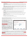
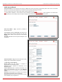
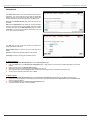
Mail Settings
The System Mail Settings page gives a possibility to send warnings automatically about the board status or problems to the administrator. System
events that require email notification are selected on the Events page. Besides, system mail has to be enabled and the SMTP server needs to be
configured for voice message transmission to the extension user’s mailing account.
217H
Enable enables the system mail sending possibility and voice
messages transmission to the extension user’s mailbox.
SMTP Host requires the SMTP host IP address or domain
name. The SMTP host needs to be configured to enable voice
message transmission.
Mail Sender Address requires the source address for the
Quadro notification emails. The email address defined here
should be an existing valid email address registered on the
selected SMTP server or should have permission to use that
particular SMTP server for emails transmission.
Mail Recipient Address requires an active email address. The
e-mail recipient here can be a Quadro administrator or someone
responsible for network and system problems.
Enable SMTP Authentication has to be selected if the
specified SMTP server requires an authentication. In this case,
authentication User Name and Password configured on the
SMTP server should be defined in the corresponding text fields.
Send Test Mail is used to initiate a test e-mail transmission.
This button will be enabled if correct values have been
submitted and saved on this page.
Fig. II-33: System Mail Settings page
To configure the System Mail
1.
2.
3.
4.
5.
6.
7.
8.
Enable the system mail sending by the Enable checkbox selection.
Update or set the SMTP host in the SMTP Host text field.
Update or set the e-mail sender address in the Mail Sender Address text field.
Update or set the e-mail address in the Mail Recipient Address text field.
Enable SMTP Authentication if it is required of the server.
Insert into the corresponding text fields an authentication User Name and a User Password defined by your SMTP server.
Press the Save button to submit these settings.
Use the Send Test Mail button to send a test e-mail with the configured settings.
QuadroE1/T1; (SW Version 3.0.x)
25
QuadroE1/T1 Manual II: Administrator's Guide
Administrator's Graphical User Interface
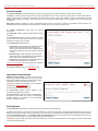
Firmware Update
This window allows to update the software of Quadro by installing new firmware called image. Users registered at Epygi will receive a notice when
new firmware is available and will be able to download it from the Epygi Technical Support WEB page.
Updating a new firmware requires a perfectly working power supply. Therefore Quadro is provided with a battery (accumulator). If the battery is low
or simply absent the “There is no battery or voltage is low” warning is displayed
Please Note: Installing new firmware will take about 15 minutes.
During this time, the QuadroCS, telephony and Internet access
will be disabled.
The firmware update will cause the loss of the following data:
•
•
•
•
•
•
DHCP leases
Transfer statistics
Call statistics
All pending events
User specific GUI states
All custom (user recorded) voice messages
The following main processes will be stopped during the
firmware update and will be restarted afterwards:
•
•
•
Voice Software
Network Time Protocol Daemon
Network Interface Statistic Daemon
Please Note: If you consider the Call Statistics entries in the
displayed tables to be important, it is recommended to download
them from the corresponding page prior to starting the Firmware
Update.
218H
Next will move you to the second page of Firmware Update
where the image file should be selected.
Fig. II-34: Firmware Update page 1
The second page of Firmware update has the Browse button
used to browse the image file, and the Specify Image text field
that will display the selected image filename.
Pressing Save will start uploading the image file to the board.
The next page will be displayed, showing the result of a
verification of the image being burned.
Fig. II-35: Firmware Update page 2
This page displays non-editable information about the image
validity. The Image Check will display invalid if the image does
not correspond to the hardware version.
The fields Current Software Version and New Software
Version show the old software version and the version of the
new image.
This page needs a confirmation to continue image updating. If
you are sure that the image version is appropriate for your
device press Save.
Fig. II-36: Firmware Check page
QuadroE1/T1; (SW Version 3.0.x)
26
QuadroE1/T1 Manual II: Administrator's Guide
Administrator's Graphical User Interface
Networking Tools
The Networking Tools provide the possibility to check the Internet connection.
Ping sends four ICMP (Internet Control Message Protocol) requests with a default size of 64 bytes to the destination (IP address or host name)
specified in the text field Ping Target. The response times are logged, and the round trip time (the time required from being sent until being received
again) is measured. The results are displayed in the lower area of the page: The minimum and maximum round trip time and its average, the
percentage of lost and of received frames.
Traceroute checks the Internet connection by triggering the routers (hops) that are passed to reach the destination specified in the text field
Traceroute Target. Trace routing gives feedback on the routers passed by packets on the way toward the destination and the round trip delay of
packets to these routers.
Attention: No Traceroute is possible if a high priority
Firewall has been enabled (see chapter Firewall and NAT).
219H
For the purpose of tracerouting, several IP packets are sent
out. UDP (User Datagram Protocol) is used to send packets
and ICMP (Internet Control Message Protocol) is used to
receive information about the routers. In their headers, the
TTL (Time To Live) value increases from 1 to 30. When the
first IP frame is received by the first router, its IP address will
be returned in its acknowledgement
The second frame delivers the IP address of the second
router and so on and so forth. The results of Traceroute are
displayed on the lower area of the page.
Ping Target requires the destination (IP address or host
name) for the ICMP request.
The Ping button starts pinging the specified ping target.
Traceroute Target is used to enter the IP address or host
name of the destination to be trace routed.
The Traceroute button is used to process the router
triggering to check the Internet connection.
In the field below the output of the Ping or Traceroute
procedure is shown.
Fig. II-37: Networking Tools page
To Check the Internet connection
1.
2.
3.
4.
Specify destination address for the ICMP request in the Ping Target text field.
Press the Ping button to process the ICMP request.
Specify the destination address to trace the route.
Press the Traceroute button to process the router triggering.
QuadroE1/T1; (SW Version 3.0.x)
27
QuadroE1/T1 Manual II: Administrator's Guide
Administrator's Graphical User Interface
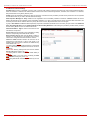
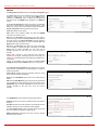
Diagnostics
The System Diagnostic page gives a possibility to run Network
and WAN protocol diagnostics, to verify Quadro's connectivity and
to download all system logs for possible problems recovery.
The Start Detecting WAN Protocol button is used to initiate WAN
diagnostics that will detect the WAN IP configuration: static or
through DHCP and PPP servers. For static WAN IP configuration,
gateway availability is checked. When acting as a client, DHCP
and PPP servers' accessibilities are being verified.
The Start Network Diagnostics button is used to initiate network
diagnostics, i.e., to check the WAN link and IP configuration, to
verify gateway, DNS primary and secondary (if configured) servers'
accessibilities.
The Start E1/T1 Diagnostics button is used to initiate E1/T1 Link
Diagnostic and Diagnostic Loopback. With these tests E1/T1
physical link is checked, Frame Synchronization and Red Alarm
states are verified. For successful Link Diagnostic, remote side
should have Line_loopback or Payload_loopback settings
configured or a loopback terminator should be plugged to the
Quadro's E1/T1 port. Diagnostic Loopback will be initiated if Link
Diagnostic is failed or E1/T1 link is down.
The field below will display the diagnostics results and the
connectivity conditions. The system should be reconfigured if
problems occur during the diagnostics.
The Download system logs button is used to download all logs to
the local PC as a *.tar archive file. These logs can then be used by
the Epygi Technical Support Office to determine the problem that
had occurred on your Quadro.
The Reboot this Device button is used to reboot the Quadro.
Please note that the session with the Quadro will be closed, i.e.,
the Quadro GUI should be newly opened and a new login will be
required afterward.
Fig. II-38: System Diagnostic page
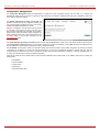
Automatic Provisioning
Automatic Provisioning gives a possibility to automatically
configure the WAN network settings of Quadro. This is very useful,
when the administrator is not actually aware about the Quadro’s
network settings. Automatic Provisioning automatically detects
the matching network configuration settings and by applying them
on the Quadro, it connects the device to the internet through the
available ISP connection.
Please Note: Automatic Provisioning can be run only from the
LAN side of the Quadro, i.e. from the PC connected to the
Quadro’s LAN.
Automatic Provisioning automatically detects and configures the
following settings on the Quadro:
•
•
•
•
•
•
•
WAN interface type (PPPoE or Ethernet)
WAN IP settings
PPP settings
ISP settings
DHCP settings
DNS settings
NAT Traversal settings
Fig. II-39: Auto Provisioning page
QuadroE1/T1; (SW Version 3.0.x)
28
QuadroE1/T1 Manual II: Administrator's Guide
Administrator's Graphical User Interface
Features
This page lists all features, that may be activated by a software
key, characterized by a Feature Description and provided with its
Status:
•
•
•
No Key Found - the feature is currently not available
Reboot Needed - the feature key has been entered and
Quadro has to be rebooted
Activated - the feature is available
Following features may be activated via the software key:
•
Fig. II-40: Features page
Debug – enabled Telnet connection towards the Quadro
for debugging purposes.
•
H.323 Support - enables H.323 IP protocol support on the
QuadroGW.
A page with the text field Feature Key is opened. Enter the key
and press Save. The status of the selected feature entry will
change to Reboot needed. Reboot the Quadro and the feature will
get the status Activated.
To get a Feature Key register the Quadro device and send a
corresponding request to Epygi's Technical Support. This request
must include the Unique ID that is displayed in the Features page
above the features list.
Fig. II-41: Features Add page
Upload Language Pack
Upload Language Pack page allows to upload a custom language
for GUI and Voice Messages of the Quadro. The language of voice
messages can be switched to the custom Language Pack
language from GUI setting page at the System Configuration
Wizard. The language of GUI session can be changed to the
custom Language Pack language from the radio buttons on the
login page.
20H
Uploading a Language Pack will cause the loss of the following
data:
•
•
•
•
•
All internally stored voice mail
DHCP leases
Call statistics
Pending events
Transfer statistics
Please Note: Only one custom Language Pack can be uploaded
at the time. Uploading a Language Pack will remove the existing
one (if existing) and will reboot the Quadro.
Fig. II-42: Upload Language Pack page
Current Language Pack field displays a read only information about the custom language pack uploaded. When no custom language pack is
uploaded, field indicates “unknown”.
Below, there is a Language Pack File to Upload text field which displays the selected image filename. Browse button is used to browse the custom
language pack to be uploaded.
Remove Current Language Pack link is seen only when custom language pack is uploaded and is used to remove it from the system.
Pressing Save will start uploading the custom language pack to the board. The next page will be displayed, showing the result of a verification of the
language pack being uploaded and asks for confirmation to overwrite the existing custom language pack (if any).
After final confirmation, system will upload the selected custom Language Pack and will reboot.
QuadroE1/T1; (SW Version 3.0.x)
29
QuadroE1/T1 Manual II: Administrator's Guide
Administrator's Graphical User Interface
Users Menu
F Fig. II-44: Telephone Users Menu in Plain Theme
Fig. II-43: Telephone Users Menu in Dynamo Theme
User Management
The User Management is used to create user extensions and auto attendants on the Quadro. From this page, by clicking on the user extension,
administrator can get the extension settings pages.
Two types of user extensions can be created on the Quadro: active and inactive extensions. Active extensions are those that are attached to a line,
can place and receive calls and use available telephony services. Inactive extensions are those that are not attached to the line, they can use some
available telephony services but cannot place and receive calls.
QuadroE1/T1 has one available line and only one active extension can be configured.
Attendant extensions are dedicated to the IVR system on the Quadro, which is used by the callers to reach Quadro’s users, use remote access and
call relay services. It is possible to create Auto Attendants with the custom scenarios. By default, Quadro has one Auto Attendant extension (00)
which is undeletable.
The Extensions table is a list of all extensions and their parameters.
Fig. II-45: Users Management page
QuadroE1/T1; (SW Version 3.0.x)
30
QuadroE1/T1 Manual II: Administrator's Guide
Administrator's Graphical User Interface
The following columns are present in the table:
•
•
•
•
•
•
•
Extension - lists the 2-digit user or attendant extensions on the Quadro. This number is used for internal PBX calls.
Display Name - indicates an optional display name to identify the caller.
Attached Line - indicates the FXS or IP line corresponding extension is attached to. “R” is displayed in this column when SIP Remote
Extension (see below) functionality is enabled on the extension.
SIP Address - displays the SIP address of the corresponding extension. Column displays the full SIP address, (i.e.,
username@sipserver:port) when the Registration on SIP Server checkbox is selected. Else, if registration is disabled, the SIP address will
be displayed in the following format: “username, Proxy: sipserver:port”. If no SIP registration server or SIP server port is defined,
corresponding information will be skipped in this column. If no username is defined, the extension number will be displayed instead.
H323 Address - displays the H.323 address of the corresponding extension. Column displays the full H.323 address, (i.e.,
username@h323gatekeeper:port) when the Registration on Gatekeeper checkbox is selected. Else, if registration is disabled, the
Gatekeeper address will be displayed in the following format: “username, Proxy: h323gatekeeper:port”. If no Gatekeeper Registration
Address or Gatekeeper Registration Port is defined, corresponding information will be skipped in this column. If no username is defined, the
extension number will be displayed instead.
Call Relay - indicates whether or not Call Relay option is enabled on the extension.
Codecs – column lists the short information (full information is seen in the tool tip) about extension specific voice Codecs. Extension
codec’s can be accessed and modified by clicking on the link of the corresponding extension’s Codecs. The link leads to the Extension
Codecs page.
21H
Add opens the Add Entry page where the type and the
number of new extension should be defined. Page consists of
the following components:
Extension text field is used to enter a new extension number.
The extension number is a two-digit number. If non-digit
symbols have been entered, the error “Incorrect Extension: no
symbol characters allowed” occurs. If the extension length is
shorter than 2 digits, the error “Incorrect Extensions length” will
prevent the creation of the extension. If an extension with the
same number already exists in the User Management table,
the error “Extension already exists” will appear.
Please Note: Extension number cannot start with digits 0, 8 or
9.
Type drop down list is used to select the type of the extension
(user or attendant) to be created.
Fig. II-46: User Management - Add Entry page
Edit opens the Edit Entry page where a newly created user or
attendant extension settings might be adjusted. To operate with
Edit, one or more record(s) have to be selected, otherwise an
error will occur: “No records selected”.
The Edit Entry page for user extensions is divided into
following areas and requires the data necessary to configure a
user extension.
1. Extension Settings
This group requires personal extension information and has the
following components:
Extension field indicates non editable information about
extension number.
Display Name is an optional parameter used to recognize the
caller. Usually the display name appears on the called party’s
phone display whenever a call is performed or a voice mail is
sent. The field is not limited regarding symbol usage and length.
Password requires a password for the new extension.
The extension password may only contain digits. If non-numeric
symbols are entered an “Incorrect Password: no symbol
characters allowed” error will prevent making the extension.
Confirm Password requires a password confirmation. If the
input is not corresponding to the one in the Extension
Password field, the error will appear: “Incorrect Password
confirm”.
Attached Line lists all free lines to where an extension may be
attached.
Fig. II-47: User Management - Edit Entry page
QuadroE1/T1; (SW Version 3.0.x)
31
QuadroE1/T1 Manual II: Administrator's Guide
Administrator's Graphical User Interface
Allow Call Relay enables the current extension to be used to access the Call Relay service in the Quadro’s Auto Attendant. It is recommended to
define a proper and non-empty password when enabling this feature in order to protect the Call Relay service from an unauthenticated access.
SIP Registration Settings
This group requires the SIP registration settings for the extension and requires the following fields to be filled in:
Registration User Name requires a user name for the extension registration on the SIP server. The registration user name needs to be unique on
the SIP server and is being displayed on the called phone whenever performing an IP call.
Registration Password indicates the password for the extension registration on a SIP server.
Confirm Registration Password is used to confirm the password. If the entered password does not correspond to the one given in the
Registration Password field, the error will appear: “The passwords do not match. Please try again”.
Registration SIP Server indicates the host address of the SIP server. The field is not limited regarding symbol usage and length as it can be either
an IP address, e.g., 192.168.0.26 or a host address, e.g., sip.epygi.com.
Registration SIP Port indicates the host port number to connect to the SIP server. The SIP server port may only contain digit values, otherwise the
error message “SIP Server Port is incorrect” will be displayed when applying the extension settings. If the SIP server port is not specified, Quadro will
access the SIP server through the default port 5060.
Registration on SIP Server enables the SIP server registration option. If the extension has already been registered at some SIP server, its IP
address will be displayed in brackets.
The Advanced Settings link appears only in the Edit Entry page and leads to the SIP Advanced Settings page, where the Outbound Proxy,
Secondary SIP Server and Outbound Proxy for the Secondary SIP Server and other settings can be configured.
2H
H323 Registration Settings
Enable H323 checkbox enables H323 protocol support on the extension. If this feature is enabled, corresponding extension is free to accept and
place H323 IP calls.
Registration User Name Type drop down list is used to choose the type of the H323 registration user name: e164, H323ID, URL or Email.
Registration User Name requires a user name for the extension registration on the H323 gatekeeper. Depending on the H323 Registration User
Name Type selected in the list above, Registration User Name inserted in this field may contain different characters: for e164 user name type digit
characters allowed only, H323ID user name type allows any characters for the registration user name, URL registration user name requires IP
address or the hostname, while Email registration user name requires an email address. The registration user name needs to be unique on the H323
gatekeeper and is being displayed on the called phone whenever performing an IP call.
Registration Password indicates the password for the extension registration on a H323 gatekeeper.
Confirm Registration Password is used to confirm the password. If the entered Password does not correspond to the one given in the
Registration Password field, the error will appear: “The passwords do not match. Please try again”.
Gatekeeper Registration Address indicates the host address of the H323 gatekeeper. The field is not limited regarding symbol usage and length
as it can be either an IP address (ex: 192.168.0.26) or a host address (ex: h323.epygi.com).
Gatekeeper Registration Port indicates the host port number to connect to the H323 gatekeeper. The H323 gatekeeper port may only contain digit
values, otherwise the error message “H323 gatekeeper Port is incorrect” will be displayed when applying the extension settings. If the Gatekeeper
Registration Port is not specified, Quadro will access the H323 gatekeeper through the default port 1719.
Registration on Gatekeeper enables the H323 gatekeeper registration option. If the extension has already been registered at some H323
gatekeeper its IP address will be displayed in brackets.
The Advanced Settings link appears only in the Edit Entry page and leads to the H323 Advanced Settings page, where the User ID and H323
Gateway Settings can be configured.
23H
QuadroE1/T1; (SW Version 3.0.x)
32
QuadroE1/T1 Manual II: Administrator's Guide
Administrator's Graphical User Interface
The Edit Entry page for attendant extensions is divided into
following areas and requires the data necessary to configure a
attendant extension. Additionally this page can be accessed by
clicking on the default 00 attendant extension.
The page with the Auto Attendant settings is divided into
following areas and requires the information necessary to
configure the Auto Attendant:
1.
Attendant Settings
This group displays the non editable Attendant number for the
Auto Attendant and allows defining the Auto Attendant
extension Display Name.
2. SIP Registration Settings
This group requires the Auto Attendant SIP registration settings
and has the following components:
The Registration User Name text field defines the user name
for the registration at a SIP Server.
The Registration Password text field indicates a password for
the Auto Attendant extension registration at a SIP server.
The Confirm Registration Password text field is used to
confirm the password. If the entered password does not
correspond to the one given in the Registration Password
field, the error will appear: “The passwords do not match.
Please try again”.
The Registration SIP Server text field indicates the host
address of the SIP Server. The field is not limited regarding
symbol usage and length as it can be either an IP number, e.g.,
192.168.0.26 or a host address, e.g., sip.epygi.com.
The Registration SIP Port text field indicates the Host Port
number to connect to the SIP server. It only may consist of
numerics, otherwise the error message “SIP Server Port is
incorrect” will be displayed when attempting to save the SIP
Registration Settings. If no SIP server port is specified, Quadro
will access the SIP server through its default port 5060.
The Registration on SIP Server checkbox enables the SIP
server registration option for the Auto Attendant.
The Advanced Settings link leads to the SIP Advanced
Settings page where the Outbound Proxy, Secondary SIP
Server and Outbound Proxy for the Secondary SIP Server
and other settings can be configured.
24H
3.
Fig. II-48: User Management - Auto Attendant Settings
H323 Registration Settings
Enable H323 checkbox enables H323 protocol support on the extension. If this feature is enabled, corresponding extension is free to accept and
place H323 IP calls.
Registration User Name Type drop down list is used to choose the type of the H323 registration user name: e164, H323ID, URL or Email.
Registration User Name requires a user name for the extension registration on the H323 gatekeeper. Depending on the H323 Registration User
Name Type selected in the list above, Registration User Name inserted in this field may contain different characters: for e164 user name type digit
characters allowed only, H323ID user name type allows any characters for the registration user name, URL registration user name requires IP
address or the hostname, while Email registration user name requires an email address. The registration user name needs to be unique on the H323
gatekeeper and is being displayed on the called phone whenever performing an IP call.
Registration Password indicates the password for the extension registration on a H323 gatekeeper.
Confirm Registration Password is used to confirm the password. If the entered Password does not correspond to the one given in the
Registration Password field, the error will appear: “The passwords do not match. Please try again”.
Gatekeeper Registration Address indicates the host address of the H323 gatekeeper. The field is not limited regarding symbol usage and length
as it can be either an IP address (ex: 192.168.0.26) or a host address (ex: h323.epygi.com).
Gatekeeper Registration Port indicates the host port number to connect to the H323 gatekeeper. The H323 gatekeeper port may only contain digit
values, otherwise the error message “H323 gatekeeper Port is incorrect” will be displayed when applying the extension settings. If the Gatekeeper
Registration Port is not specified, Quadro will access the H323 gatekeeper through the default port 1719.
Registration on Gatekeeper enables the H323 gatekeeper registration option. If the extension has already been registered at some H323
gatekeeper its IP address will be displayed in brackets.
The Advanced Settings link appears only in the Edit Entry page and leads to the
QuadroE1/T1; (SW Version 3.0.x)
25H
33
QuadroE1/T1 Manual II: Administrator's Guide
Administrator's Graphical User Interface
H323 Advanced Settings page, where the User ID and H323 Gateway Settings can be configured.
4. Attendant Scenario
This group allows to select between default and custom attendant functionality scenarios. When Default scenario is selected, a group of settings
should be adjusted, user defined Auto Attendant welcome messages can be uploaded and the list of Friendly Phones can be configured. For
Custom scenario, scenario script file (in EpygiXML coding, the coding standard can be found at Epygi Technical Support) should be defined and
custom voice messages can be uploaded.
73H
Default manipulation radio button selection enables following components:
•
Send AA Digits to Routing Table checkbox selection switches the Auto Attendant to the routing mode. Any inserted digits in the
Connection menu will be parsed through the Routing Table on the Quadro.
Please Note: This checkbox affects ONLY Connections Menu (see Auto Attendant Services). In Call Relay Menu, the routing prefix needs
to be dialed (see Feature Codes) to parse the dialed number through the Routing Table.
•
Attendant Welcome Message - this group allows updating the active Auto Attendant welcome message, downloading it to the PC, or
restoring the default one. The group offers the following components:
The Restore Default Welcome Message checkbox allows restoring the Auto Attendant default welcome message file if another one has
been previously selected. If the checkbox is selected, the file upload will be disabled.
Upload new welcome message indicates the file name used to upload a new welcome message. The uploaded file needs to be in PCMU
wave format, otherwise the system will prevent uploading it with the “Invalid audio file, or format is not supported” warning message. The
system also prevents uploading if there is not enough memory available for the corresponding extension, which will cause the “You do not
have enough space” warning.
Browse opens the file chooser window to browse for a new welcome message file.
The Download Welcome Message File link appears only if a file has been previously uploaded. The link is used to download the audio
file to the PC and opens the file chooser window where the saving location can be specified.
•
Routing Attendant Welcome Message - this group is available for default 00 attendant only and allows updating a welcome message
played when Auto Attendant acts in the routing mode (i.e., incoming calls to FXO line or ISDN timeslot are routed to the Routing agent),
downloading it to the PC, or restoring the default one. The group offers the following components:
The Restore Default Routing Welcome Message checkbox allows restoring the routing Attendant welcome message file if another one
has been previously selected. If the checkbox is selected, the file upload will be disabled.
Upload new Routing welcome message indicates the file name used to upload a new welcome message. The uploaded file needs to be
in PCMU wave format, otherwise the system will prevent uploading it with the “Invalid audio file, or format is not supported” warning
message. The system prevents uploading also if there is not enough memory available for the corresponding extension. This will cause the
“You do not have enough space” warning.
Browse opens the file chooser window to browse for a new routing welcome message file.
The Download Routing Welcome Message File link appears only if a routing welcome message has been previously uploaded. The link
is used to download the audio file to the PC and opens the file chooser window where the saving location can be specified.
•
Friendly Phones - the Edit Authorized Phones Database link refers to the Authorized Phones Database page where trusted external
phones are listed. If they are part of the Quadro Authorized Phones database, external SIP or PSTN users are free to access the Quadro
Auto Attendant services without passing the authentication. When adding a friendly phone to the list, an existing extension has to be
chosen whose parameters (extension number and password, as well as SIP/H.323 and Speed Calling Settings) will be used automatically
for the trusted caller access of the Quadro Auto Attendant. A direct connection to the Call Relay menu can be provided optionally.
The Authorized Phones Database page displays the
Authorized Phones Database table where the trusted
phones are listed. Only SIP and PSTN users can be
added to the Authorized Phones Database.
The Authorized Phones Database table displays all
trusted callers with their settings, e.g., call type, caller
address, extension they automatically login with,
information if they have automatic access to Auto
Attendant (Call Relay Menu, etc.).
Fig. II-49: Authorized Phones Database
Each record in the table has an assigned checkbox. The checkbox is used to edit or delete the corresponding record. The “No records selected”
error occurs if the user activates the edit or delete button having no records selected. The error “One record should be selected” appears if the user
tries to edit more than one record. Each column heading in the table a link. By clicking on the column heading, the table will be sorted by the selected
column. Upon sorting (ascending or descending), arrows will be displayed close to the column heading.
The Add functional button refers to the Authorized Phones Database- Add Entry page where new trusted users may be entered.
QuadroE1/T1; (SW Version 3.0.x)
34
QuadroE1/T1 Manual II: Administrator's Guide
Administrator's Graphical User Interface
The Authorized Phones Database- Add Entry page offers
two group of input options:
Caller Settings
The Call Type drop down list includes possible incoming call
types (PSTN or SIP). In SIP, the caller connects Quadro
through a SIP server and PSTN means the caller is a PSTN
user.
The Caller Address text field requires the caller’s SIP
address (see chapter Entering a SIP Addresses correctly) or
PSTN number to be added to the trusted phones’ list. The
PSTN number length depends on the area code and phone
number. The wildcard is supported in this field. If the caller
address already exists in the Authorized Phones Database,
the error “The record already exists” appears when selecting
the Save button.
26H
Fig. II-50: Authorized Phones Database - Add Entry page
H323 Alias field is actual for H323 call type only and may contain different characters: for e164 user name type digit characters allowed only, h323ID user name type allows any characters for the registration user name.
The Login Extension drop down list provides all existing extensions on the Quadro. When calling the Quadro Auto Attendant, a trusted user will
automatically login with the selected extension, i.e., extension number and its password will be automatically submitted by the Quadro system. The
trusted user will directly access the Quadro Auto Attendant services. The SIP settings of login extension will be used while making IP calls.
The Automatically Enter Call Relay Menu checkbox enables direct access for the trusted user to the Quadro Auto Attendant Call Relay menu. If
the checkbox is not selected, a trusted caller will be directed to the Auto Attendant's main menu, but still will be able to reach Remote Access (Voice
Mailbox of the specified extension) and Call Relay services (see Feature Codes) with no authentication.
The Description text field allows to enter an optional comment.
Custom manipulation radio button selection allows to upload Attendant’s custom scenario file and voice messages:
Upload Scenario File indicates the file name used to upload a new scenario file. The uploaded file needs to be in EpygiXML format (the coding
standard can be found at Epygi Technical Support) and is restricted to 20KB file size. Browse opens the file chooser window to browse for a
custom scenario file.
The View/Download Scenario link appears only when a custom scenario file has been previously uploaded and is used to view or download the
scenario file. Remove Scenario link is used to remove a custom scenario file and to turn to default Auto Attendant scenario.
Upload Custom Voice Messages link refers to the same named page where voice messages used in the uploaded custom scenario should be
managed.
74H
This page provides a possibility to upload voice messages to be
played in the custom Auto Attendant scenario, as well as to
remove and to download the uploaded files to PC.
Upload Custom Voice Messages page contains a table where
uploaded custom voice messages are listed. Use Download
functional button to download and Remove to delete the
corresponding custom voice message. Browse opens a file
chooser window to browse for a custom voice message.
Fig. II-51: Upload Custom Voice Messages page
Custom Hold Music - this group is available for default 00 attendant only and allows updating default hold music for all those extensions that use
the factory default hold music. The group offers the following components:
The Restore Default Hold Music checkbox allows restoring the default hold music if another one has been previously selected. If the
checkbox is selected, the file upload will be disabled.
Upload Default Hold Music indicates the file name used to upload default hold music. The uploaded file needs to be in PCMU wave
format, otherwise the system will prevent uploading it with the “Invalid audio file, or format is not supported” warning message. The system
prevents uploading also if there is not enough memory available for the corresponding extension. This will cause the “You do not have
enough space” warning.
Browse opens the file chooser window to browse for a default hold music file.
The Download Default Hold Music link appears only if default hold music has been previously uploaded. The link is used to download the
audio file to the PC and opens the file chooser window where the saving location can be specified.
QuadroE1/T1; (SW Version 3.0.x)
35
QuadroE1/T1 Manual II: Administrator's Guide
Administrator's Graphical User Interface
The Edit functional button provides a possibility of editing multiple
extensions. In this case, fields that cannot be edited for multiple
records have Multiple values in the Edit Entry page. When editing
user and attendant extensions together, Edit Entry page displayed
only those fields that are general for both user extension and
attendant settings. Additionally, for the fields that need to be
modified, a Select to modify fields checkbox alongside the
corresponding field needs to be selected to submit changes,
otherwise the fields will not be updated.
Delete removes the selected extensions. If no records are selected
an error message occurs.
Fig. II-52: User Management - Edit Entry page for multiple edit operation
To Configure a User Extension
1.
2.
3.
4.
Press the Add button on the User Management page. The Add Entry page will appear in the browser window.
Enter the desired extension number in the Extension text field and select “User Extension” in Type drop down list.
Press Save to create a user extension with the defined number.
Select the checkbox of the newly created extension in the User Management table and press Edit button. The Edit Entry page will appear in
the browser window.
5. Define the extension name in the Display Name text field.
6. The extension password has to be entered into the Password text field and confirmed in the Confirm Password text field.
7. To attach the extension to a line, select a line from the Attached Line drop down list. Now the attached extension is ready to receive and
perform calls.
8. Enable Call Relay option if needed.
9. Configure SIP Registration Settings (SIP server, port number, SIP registration user name, and the password) and Enable Registration on
SIP Server, if needed.
10. Configure H323 Registration Settings (Enable H.323, Gatekeeper Registration Address, Gatekeeper Registration Port, Registration user
name, and the password) and enable Registration on Gatekeeper, if needed.
11. Configure Advanced SIP Settings (User ID, Send Keep-alive Messages to Proxy, Outbound Proxy, Secondary SIP Server and Outbound
Proxy for Secondary SIP Server).
12. To apply extension settings, press Save.
To Configure an Attendant Extension
1.
2.
3.
4.
Press the Add button on the User Management page. The Add Entry page will appear in the browser window.
Enter the desired extension number in the Extension text field and select “Attendant” in Type drop down list.
Press Save to create an attendant extension with the defined number.
Select the checkbox of the newly created extension in the User Management table and press Edit button. The Edit Entry page will appear in
the browser window. To access Edit Entry page for default 00 attendant extension, simply click on extension number in User Management
table and skip 1-4 steps of this guidance.
5. Define the Attendant Display Name in the corresponding text field.
6
Configure SIP Registration Settings (SIP server, port number, SIP registration user name, and the password) and Enable Registration on
SIP Server, if needed.
7. Configure Advanced SIP Settings (User ID, Send Keep-alive Messages to Proxy, Outbound Proxy, Secondary SIP Server and Outbound
Proxy for Secondary SIP Server).
8. Configure H323 Registration Settings (Registration Gatekeeper Address, port number, Registration user name, and the password) and enable
Registration on Gatekeeper, if needed.
9. Configure Advanced H323 Settings (User ID and H323 Gateway Settings).
10. Choose between Default or Custom Attendant Scenario modes. For Default Attendant Scenario mode, Send AA digits to Routing table
checkbox can be enabled, if needed, as well as Attendant Welcome Message and Attendant Routing Welcome Message can be uploaded,
restored or downloaded to PC. Additionally Friendly Phones allowed to connect to Quadro’s Auto Attendant can be configured by pressing the
Edit Authorized Phones Database link. For Custom Attendant Scenario mode, Attendant’s custom scenario file can be uploaded and a list
of custom voice messages can be configured.
To Delete an Extension
QuadroE1/T1; (SW Version 3.0.x)
36
QuadroE1/T1 Manual II: Administrator's Guide
1.
2.
3.
Administrator's Graphical User Interface
To remove an extension with all its settings select one or more checkboxes of the corresponding extensions that ought to be deleted from the
User Management table. Press Select all if all extensions ought to be deleted.
Click on the Delete button on the User Management page.
Confirm the deletion with Yes. The extension will be deleted. To abort the deletion and keep the extension in the list, click No.
To Add an Authorized phone to the database
1.
2.
3.
4.
5.
6.
7.
8.
Enter the desired Auto Attendant Settings page.
Select Edit Authorized Phones Database to enter the Authorized Phones Database page.
Press the Add button on the Authorized Phones Database page. The Add Entry page will appear in the browser window.
Choose the call type and enter a caller address in the corresponding text field.
Select a Login Extension and the Automatically Enter Call Relay Menu checkbox (if needed).
Enable Call Back service if needed and define a Call Back Destination in the same named field.
Fill in an optional Description in the appropriate field, if needed.
Press Save to submit the settings.
To Delete an Authorized phone from the database
1.
2.
3.
4.
5.
Enter the desired Auto Attendant Settings page.
Select Edit Authorized Phones Database to enter the Authorized Phones Database page.
To remove an authorized phone(s), select one or more checkboxes of the corresponding records that ought to be deleted from the Authorized
Phones Database table. Press Select all if all records ought to be deleted.
Press the Delete button on the Authorized Phones Database page.
Confirm the deletion with Yes or cancel with No.
SIP Advanced Settings
The SIP Advanced Settings page is used to configure the Outbound Proxy, Secondary SIP Server and Outbound Proxy for the Secondary SIP
Server settings and to define other SIP server specific settings.
SIP Outbound proxy is such a SIP server, where all the SIP requests and other SIP messages are transferred. Some SIP servers use an outbound
proxy server to escape restrictions of NAT, e.g., Free World Dialup service uses an Outbound Proxy server. If an Outbound proxy is specified for an
extension, all SIP calls originating from that extension are made through that outbound proxy, i.e., all requests are sent to that outbound proxy, even
those call by Speed Calling.
The Secondary SIP Server acts as an alternative SIP registration server when the primary SIP Registration Server (defined from the SIP Registration
Settings page) is inaccessible. If the connection with the primary SIP server fails, Quadro will automatically start sending SIP messages to the
Secondary SIP Server, and will switch back to the primary SIP server, as soon as its connection is reestablished.
The SIP Advanced Settings page consists of the following
components:
UserID requires an identification parameter to reach the SIP
server. It should have been provided by the SIP service
provider and can be requested for some SIP servers only, for
others, the field should be left empty.
Send Keep-alive Messages to Proxy enables the SIP
registration server accessibility verification mechanism.
Timeout indicates the timeout between two attempts of SIP
registration server accessibility verification. If no reply is
received from the primary SIP server within this timeout, the
Secondary SIP server will be contacted. When the primary SIP
server recovers, SIP packets will be sent to it once again.
A group of Host address and Port text fields respectively
require the host address (IP address or the host name), the
port number of the Outbound Proxy, Secondary SIP Server
and the Outbound Proxy for the Secondary SIP Server.
These settings are provided by the SIP servers’ providers and
are used by Quadro to reach the selected SIP servers.
RTP Priority Level drop down list is used to select the priority
(low, medium or high) of RTP packets sent from corresponding
extension. RTP packets with higher priority will be preceded
first in case of heavy traffic.
Fig. III- 105 Extension Advanced SIP Settings page
H323 Advanced Settings
The H323 Advances Settings page is used for the H.323 gateway settings configuration to allow Quadro extension to use services provided by the
H.323 gateway. Depending on the H.323 gateway configuration, it can provide call routing services to the different type of networks (e.g. PSTN).
QuadroE1/T1; (SW Version 3.0.x)
37
QuadroE1/T1 Manual II: Administrator's Guide
Administrator's Graphical User Interface
The UserID (Alias Name) text field requires an
identification parameter to reach the H323 Gatekeeper. It
should be provided by the H323 service provider and can
be requested for some H323 Gatekeepers only, for others
field should be left empty.
The Address text field requires the IP address or the host
name of the H.323 gateway. The Port text field requires
the port number of the H323 gateway.
The Dial Access Plan text field requires a service
identification number H323 gateway provides to the
extension. This option is independent from the Address
and Port parameters, i.e. can be also configured when
other two fields are empty.
Address, Port and the Dial Access Plan are provided by
the H.323 service provider and are used by Quadro to set
the H.323 gateway specific features.
Please Note: Address and Port settings specified here
will be only used when extension is not registered on the
H.323 gatekeeper (and will be ignored in the contrary
case), also when originating the H.323 IP call using shared
H.323 registration settings of this extension.
Fig. III- 205 Extension Advanced H.323 Settings page
Extension Codecs
To establish IP voice communication, both partners have to use the same codec. During establishing the communication line, this codec is
negotiated. If the caller does not find a fitting codec, the communication cannot take place. So, if you want to be reachable by preferably all IP calls, it
is helpful to support as many codecs as possible. In this case, all the codecs that Quadro offers should be added to the Active Codecs table. On the
other hand, some codecs require a high transfer rate - up to 64 kbit/s. If you are certain you do not want to use these codecs, you have to make sure
they are not listed in the table Active Codecs.
The Extension Codecs page displays a list of Active
Codecs and the state of the Out of Band DTMF and FAX
Support features for Quadro extensions (also Auto
Attendant).
Please Note: Use caution when configuring Auto Attendant
Codecs as they are used by virtual extensions for
redirecting the incoming calls.
The table Active Codecs lists active voice codecs for the
selected line that are supported by Quadro. The order of
records in the Active Codecs table is important for
transmitting and receiving. A codec placed at the top of the
table will be used as the preferred codec. If the remote
party does not support the preferred codec, the following
codecs will be tried out in a top-down order in the Active
Codecs table.
Each record in the table has an assigned checkbox. It is
used to select the record to be deleted or moved up or
down.
An error occurs if no records are selected and the user
activates the delete button: “No records selected”. At least
one codec must be attached to the line. When attempting to
delete the last codec, this error will occur: “At least one
codec should stay in the codec list”.
Fig. II-53: Extension Codecs list
Add opens the Add Entry page where the user may add
codecs supported by Quadro. The voice codec defines the
voice compression algorithm for the incoming and outgoing
DSP packages.
Codecs lists all codecs supported by Quadro. If no more
codecs are available (all available codecs have already
been transferred to the Active Codecs table), the Add
Entry page will display the message “No Available Codecs”
instead of the drop down menu.
Fig. II-54: Extension Codecs - Add Codec page
The Move Up/Move Down buttons are used to move the selected codec one level up/down in the table.
QuadroE1/T1; (SW Version 3.0.x)
38
QuadroE1/T1 Manual II: Administrator's Guide
Administrator's Graphical User Interface
The Out of Band DTMF Transport checkbox enables DTMF code transmission in parallel with the voice stream. The destination receiving the
DTMF code will play it locally if it supports the feature. This is helpful to avoid DTMF’s loss upon bad traffic. This feature is valuable for all codecs but
it is especially recommended to enable it in case low bit rate codecs (G729, G723, G726/16, etc.) are selected.
Enable FAX Support checkbox enables the FAX tone detection and the T.38 codec support for the FAX transmission from/to the Fax Machine/Fax
modem attached to the line.
T.38 Invite Only checkbox is available when FAX support is enabled and restricts connection establishment to T.38 codec for the corresponding
extension, i.e. only T.38 codec will be used.
Attention: Selecting the T.38 Invite Only checkbox will deny common outgoing calls on the extension. These checkboxes take effect ONLY on FXS
lines.
Force Self Codecs Preference for Inbound Calls checkbox enables the usage of the own preferred codecs (if available on both peers) for the IP
connection establishment on the extension.
Change Admin Password
The Change Admin Password page provides information about the administrator account name and allows changing the administrator password.
It offers the following components:
Old Password requires the current password. An error
message prevents from entering a wrong one.
New Password requires the new password, which has to be
confirmed in Confirm New Password.
The password may consist of numerical values only. A
corresponding warning appears if any other symbols are
inserted.
Please Note: When reloading a former configuration, the
administrator’s password specified here is still valid, as the
administrator’s password is not saved with the configuration.
Fig. II-55: Change Password page
QuadroE1/T1; (SW Version 3.0.x)
39
QuadroE1/T1 Manual II: Administrator's Guide
Administrator's Graphical User Interface
Telephony Menu
Fig. II-57: Telephony Menu in Plain Theme
Fig. II-56: Telephony Menu in Dynamo Theme
Call Statistics
The Call Statistics page displays four tables and provides information on successful, unsuccessful and missed incoming and outgoing calls on the
first three tables, and statistics settings on the fourth page. Call statistics allows the collecting of call events on the Quadro with their parameters and
to search them by various criteria.
The Statistics Settings page offers the following input options:
The Enable Call Reporting checkbox enables Call Statistics
reporting. The selected number of statistics entries will be
displayed in the Call Statistics tables.
The Maximal Number of Displayed Call Records drop down
lists are used to select the number of Successful, Missed and
Nonsuccessful statistics entries to be displayed in the
corresponding Call Statistics tables. If the record numbers
exceed the numbers specified in these drop down lists, the
oldest record will be removed.
The Download Call Statistics link is used to download all
displayed statistics in a file that can be viewed with a simple text
editor.
The Clear all Records button is used to clear all statistics
records.
Fig. II-58: Call Statistics Settings page
The Number of Records displays the current number of
statistics entries in the table. For the successful calls, Total
Duration, Maximum Duration, Average Duration and
Minimum Duration statistics are displayed on top of the table.
The Call Statistics: Successful Calls, Missed Calls and
Nonsuccessful Calls pages consist of the general information
on successful, missed and unsuccessful calls, search fields and
the calls table. The search components are as follows:
The From and To text fields are used to search by date and
time. The data has to be entered in either of the following
formats: dd-mm-yyyy hh:mm:ss or dd-Mon-yyyy hh:mm:ss. The
time criteria is optional. From requires an earlier date and time
than the To field. If the entered data does not meet this
condition, the error message “Minimal date should be less than
maximal date” prevents statistics filtering.
The From and To drop down lists are used to search by
duration. The duration has to be selected from the list values.
The From field has to indicate a shorter duration than the To
field. If the inserted data does not meet this condition, the error
message “Minimal duration should be less than maximal
duration” prevents statistics filtering.
Calling Phone and Called Phone respectively require the caller
and called party’s SIP address (see chapter Entering a SIP
Addresses correctly), extension or PSTN number as search
27H
QuadroE1/T1; (SW Version 3.0.x)
Fig. II-59: Call Statistics page
40
QuadroE1/T1 Manual II: Administrator's Guide
Administrator's Graphical User Interface
criteria. Wildcard symbols are allowed here.
The Call Statistics: Successful Calls, Missed Calls and
NonSuccessful Calls tables are lists of successful, missed and
unsuccessful incoming and outgoing calls and their parameters
(Call Start Time, Call Duration, Call destinations). Each column
heading in the tables is a link. By clicking on the column
heading, the table will be sorted by the selected column. Upon
sorting (ascending or descending), arrows will be displayed
close to the column heading.
Network Details column is present in Successful Calls table
only and provides brief information about the call quality and
codecs used for receive and transmit packets. Clicking on the
successful call details will open RTP Statistics page where
detailed information (Call Quality, Receive and Transmit
Codecs, Number of Packets and Packet Sizes, Number of
Received Lost Packets, Receive Jitter and Receive Maximum
Delay) about the established call is provided. Call Detail column
is present in Non Successful Calls table only and indicates the
reason of the call being unsuccessful.
28H
Filter performs a search procedure by the selected criteria. The
search may be done with several criteria at once.
To Enable/Disable the Statistics
1.
2.
3.
4.
Enter the Call Statistics Settings page.
Select/deselect the Enable Call Reporting checkbox to enable/disable statistics recording.
If enabling the statistics, the maximum number of records to be stored in the statistics table should be selected from the corresponding drop
down lists.
Press Save to apply the new configuration.
To Filter the Statistics
1. Enter the desired criteria fields.
2. Press the Filter button to search the call reports within the Call Statistics table.
Please Note: To return to the complete Statistics Table clear all search criteria and press Filter.
To Reset the Statistics
1.
2.
Press the Clear All Records button in the Call Statistics Settings page.
Confirm the deletion with Yes. The call statistics will be deleted. To abort the deletion and keep the statistics information, click No.
RTP Statistics
The RTP Statistics page provides detailed information (Call Quality,
Receive and Transmit Codecs, Number of Packets and Packet Sizes,
Number of Received Lost Packets, Receive Jitter and Receive
Maximum Delay) about the established call is provided.
Below is the legend for Call Quality definitions on the displayed RTP
Statistics:
excellent - lost packets <= 1% & max_arrival_delay <= 100 ms
good - lost packets <= 5% & max_arrival_delay <= 200 ms
satisfactory - lost packets <= 10% & max_arrival_delay <= 400 ms
bad - lost packets <= 20% & max_arrival_delay <= 600 ms
very bad - lost packets > 20% or max_arrival_delay > 600 ms
QuadroE1/T1; (SW Version 3.0.x)
Fig. II-60: RTP Statistics page
41
QuadroE1/T1 Manual II: Administrator's Guide
Administrator's Graphical User Interface
SIP Settings
The SIP Settings provide information on the SIP receive UDP and TCP ports and allows to select DNS server configuration for SIP and SIP timers
scheme.
UDP Port indicates the SIP UDP (User Datagram Protocol)
receive port number. By default 5060 is selected and used. The
SIP UDP port cannot be in the selected RTP/RTCP port range
for FXS and IP lines (see RTP Settings), otherwise the “Mapped
port for SIP shouldn’t be in RTP port range” error appears.
29H
TCP Port indicates the SIP TCP (Transmission Control
Protocol) receive port number. By default 5060 is selected and
used.
Please Note: Quadro will not use TCP protocol as a transport
for SIP messages if the TCP Port field is left empty.
Enable Session Timer enables advanced mechanisms for
connection activity checking. This option allows both user
agents and proxies to determine if the SIP session is still active.
Fig. II-61: SIP Settings page
The DNS server for SIP radio button group allows to choose between regular DNS servers configured in the DNS Settings page and specific DNS
servers for the SIP traffic.
230H
•
•
Use default is used to apply regular DNS servers for the SIP traffic.
Specific is used to enable SIP specific DNS servers. For this selection, both primary and secondary SIP DNS servers should be defined in the
SIP DNS 1 and SIP DNS 2 text fields. At the least, a primary DNS server should be inserted.
The SIP Timers radio button group is used to define the timeouts of the SIP messages retransmission.
•
•
•
RFC 3261 will apply standard SIP timers described in the corresponding specification.
High availability will apply SIP timers to shorten the call establishment, registration confirmation and registration failure procedures. This
selection provides more firmness to the SIP connection but increases the network traffic on the Quadro.
Custom allows defining manually the Registration Timeout, Registration Failure Timeout, Transaction Duration and Session refresh
timeout SIP timers (in seconds).
H323 Settings
The H323 Settings provide information on the H.225 RAS receive UDP port and H.323 TCP port range, enable H323 specific options as well as
allows to enable the NAT traversal for the H.323 traffic.
QuadroE1/T1; (SW Version 3.0.x)
42
QuadroE1/T1 Manual II: Administrator's Guide
Administrator's Graphical User Interface
The text field UDP Port indicates the H.225 RAS UDP
(User Datagram Protocol) receive port number. UDP port
cannot be in the selected RTP/RTCP port range for FXS
and IP lines (see RTP Settings) otherwise error appears.
75H
The text fields TCP Min Port and TCP Max Port text fields
are used to indicate the TCP (Transmission Control
Protocol) receive port range for H.225 call signaling and
H.245 media negotiation. The port defined in the TCP Min
Port text field will be used for accepting the incoming
direct H.323 calls.
There are three ways to set up a H.323 call: a separate
H.245 channel, fast connect and tunneling. However, it is
not always possible to use fast connect or tunneling and a
terminal can at any time switch back to a separate H.245
channel.
Fig. II-62: H323 Settings page
Fast Connect checkbox enables media negotiation handled by the H.225 call signaling messaging without opening H.245 channel. Fast Connect
reduces the number of transmitted H.323 messages and allows the media channels to be operational before the connect request is sent and the
telephone rings.
Tunneling checkbox enables H.245 channel to be sent within the H.225 call signaling channel.
H323 timers parameters group allows to specify TCP and Setup timeouts and provides following components:
TCP Connect Timer checkbox selection enables custom values of TCP Connect Timer (in seconds). When this checkbox is enabled, TCP
Connect Timeout text field requires the time of TCP connection establishment. Connection establishment attempts are stopped if no
connection has been established within the specified timeout.
Setup Timeout text field requires a timeout (in seconds) used on sending first signaling message if there is no any answer from the
remote side.
RTP Settings
The RTP Settings page allows the administrator to configure the codec’s packet size and silence suppression for each voice codec, to select the
G726 codec standard, to define RTP/RTCP port ranges, etc. All parameters listed on this page may be modified and submitted.
The Codec Properties table lists all codecs with the
corresponding packetization interval and information about
silence suppression.
Edit opens the Edit RTP Settings page where the codec
settings can be modified. To use Edit, only one codec may be
selected at a time, otherwise an error occurs: “One record
should be selected”.
The Packetization Interval is the time interval between two
RTP packets of the same stream. If the interval is increased, the
overhead is decreased but the voice quality may deteriorate as
a result. If the interval is decreased, the network load is
increased and the delay is reduced.
Silence Suppression disables RTP packet transmission in
case of no voice activity. This feature helps to avoid extra traffic
if the RTP stream contains no voice. It is activated after two
seconds of silence and restarted immediately if any audio
appears.
The G.726 Standard radio buttons are used to select between
packaging the G.726 codewords into octets. If you experience
problems with G.726 voice quality having one of these
packaging selected, try the other one.
•
•
If Use ITU_T specification is selected, the ITU I.366.2
(“AAL2 type 2 service specific convergence sublayer for
narrow-band services”) type packaging of codewords is
used, where packing code words into octets is starting from
the most significant rather than the least significant digit in
the octet.
If Use IETF RFC is selected, the IETF RFC (“RTP Profile
for Audio and Video Conferences with Minimal Control”)
type packaging of codewords is used, where packing code
words is starting from the least significant position in the
octet.
QuadroE1/T1; (SW Version 3.0.x)
Fig. II-63: RTP Settings page
43
QuadroE1/T1 Manual II: Administrator's Guide
Administrator's Graphical User Interface
RTP/RTCP Port Range for FXS Lines:
•
•
Min - minimal port has to be higher than 1024 and lower than the maximal port range. Only even numbers are allowed.
Max - maximal port has to be lower than 65536 and higher than the minimal port range. Only odd numbers are allowed.
As the specified maximum ports has to be higher than the minimum ports, the error message “Min port number should be less than max port
number” will occur if this condition is not met. The port range may consist of digits only, otherwise the error “Incorrect Port Range: only Integer values
allowed” occurs. The difference between Max and Min RTP ports should be 50 ports or less (according to the system’s capabilities) otherwise the
corresponding warning appears. RTP/RTCP Port ranges cannot include the defined SIP UDP ports (see SIP Settings) otherwise an error appears.
231H
Telephone Event Draft Support enables telephony events transmission according to the draft-ietf-avt-rfc2833bis-04. The checkbox needs to be
toggled if the SIP destination party phone or IVR has problems recognizing DTMFs generated by the Quadro.
Enable RTCP Support enables Real Time Control Protocol support and allows for the RTCP packets transmission. RTCP protocol is used for
monitoring the RTP streams and changing RTP characteristics depending on Network conditions.
The RTP Settings – Edit Entry page offers a drop down list and a
checkbox.
Packetization Interval contains possible values (in milliseconds)
to be configured for the selected codec.
The Enable Silence Suppression checkbox selection enables
voice activity detection for the selected codec.
Fig. II-64: RTP Settings - Edit Entry
To Edit Codec Parameters
1.
2.
3.
4.
Select the codec from the Codecs Table that is to be edited.
Press the Edit button on the RTP Settings page. The Edit Entry page will appear in the browser window.
Change values in Packetization Interval and/or enable/disable Silence Suppression.
To save the codec settings press Save, or to keep the initial data click Back.
NAT Traversal Settings
The NAT Traversal Settings page is divided into separate pages used to configure SIP and H.323 NAT parameters, RTP and STUN parameters for
NAT and a page where the NAT Exclusion table may be filled.
Use NAT Traversal for SIP checkbox applies to all pages and is used to enable NAT traversal for the SIP traffic, hence any incoming and outgoing
SIP messages from and to the Quadro will be routed through the NAT PC.
Use NAT Traversal for H323 checkbox applies to all pages and is used to enable NAT traversal for the H.323 traffic, hence any incoming and
outgoing SIP messages from and to the Quadro will be routed through the NAT PC.
The SIP Parameters page is used to configure NAT specific
settings for SIP. and offers two independent group of settings:
UDP Parameters:
Manipulation radio buttons allow to select the type of connection
over NAT:
Selecting Use STUN will switch to automatic discovery of
Mapped settings for the SIP UDP traffic over NAT. STUN
settings are configured on the STUN parameters page (see
below).
Selecting Use Manual NAT Traversal allows to define
manually the mapped settings for the SIP UDP traffic over
NAT:
Mapped Host requires the IP address of the mapped host for
SIP UDP traffic over NAT.
Mapped Port requires the port number on the mapped host
for the SIP UDP traffic over NAT.
TCP Parameters:
Mapped Host requires the IP address of the mapped host for
SIP TCP traffic over NAT.
Mapped Port requires the port number on the mapped host
for the SIP TCP traffic over NAT.
QuadroE1/T1; (SW Version 3.0.x)
Fig. II-65: SIP Parameters page
44
QuadroE1/T1 Manual II: Administrator's Guide
Administrator's Graphical User Interface
The H323 Parameters page is used to configure NAT specific
settings for H.323. and offers two independent group of settings:
UDP Parameters:
Manipulation radio buttons allow to select the type of connection
over NAT:
Selecting Use STUN will switch to automatic discovery of
Mapped settings for the H.323 UDP traffic over NAT. STUN
settings are configured on the STUN parameters page (see
below).
Selecting Use Manual NAT Traversal allows to define
manually the mapped settings for the H.323 UDP traffic over
NAT:
Mapped Host requires the IP address of the mapped host for
H.323 UDP traffic over NAT.
Mapped Port requires the port number on the mapped host
for the H.323 UDP traffic over NAT.
TCP Parameters:
Mapped Host requires the IP address of the mapped host for
H.323 TCP traffic over NAT.
Mapped Port requires the port number on the mapped host
for the H.323 TCP traffic over NAT.
Fig. II-66: H323 Parameters page
The RTP Parameters page is used to choose between the
STUN and Manual NAT traversal connection for the RTP traffic
and to define the RTP/RTCP ports for the connection over NAT.
Manipulation radio buttons allow to select the type of connection
over NAT:
Selecting Use STUN will switch to automatic discovery of
Mapped settings for the RTP UDP traffic over NAT. STUN
settings are configured on the STUN Parameters page (see
below).
Selecting Use Manual NAT Traversal allows to define manually
the RTP/RTCP port ranges for the RTP traffic over NAT:
•
•
The Mapped Host text fields require the Mapped Host for
RTP traffic over NAT.
Mapped RTP/RTCP Port Range for FXS Lines:
•
Min - minimal port has to be higher than 1024 and lower
than the maximal port range. Only even numbers are
allowed.
•
Max - maximal port has to be lower than 65536 and
higher than the minimal port range. Only odd numbers
are allowed.
Please Note: RTP/RTCP Mapped Port ranges should be
greater than or equal to the RTP/RTCP port ranges defined on
the RTP Settings page.
Fig. II-67: RTP Parameters page
23H
QuadroE1/T1; (SW Version 3.0.x)
45
QuadroE1/T1 Manual II: Administrator's Guide
Administrator's Graphical User Interface
The STUN Parameters page enables automatic NAT
configuration through the STUN server and is used to configure
the STUN (Simple Traversal of UDP over NAT) client on the
Quadro. The page requires the following data to be inserted:
The STUN Server text field requires the STUN server’s
hostname or IP address. The STUN Port text field requires the
STUN server port number.
The Polling Interval drop down list contains the possible time
intervals between referrals to the STUN server.
The Keep-alive interval text field gives the possibility to select
the time interval (in seconds) for keeping NAT mapping alive.
Fig. II-68: STUN Parameters page
The NAT Exclusion Table page includes a table where all possible IP ranges are listed that allows to exclude some network addresses from being
NATed. For example, if a Quadro user needs to make SIP calls within the local network as well as outside of that network, all local IP addresses are
required to be excluded from NAT traversal settings by being listed in this table. Otherwise, a malfunction may occur in SIP operations.
The NAT Exclusion Table page offers the following input
options:
Each record in the table has its checkbox assigned to its
row. This checkbox is used to delete or to edit the
corresponding record. As only one record may be edited at
a time, an error message appears, if none or more than one
is selected.
Each column heading in the table is a link. By clicking on
the column heading, the table will be sorted by the selected
column. Upon sorting (ascending or descending), arrows
will be displayed close to the column heading.
The Add Entry page includes the following text fields:
Add opens the Add Entry page where a new IP range can
be added.
Edit opens the Edit Entry page where the IP range can be
modified. The page includes the same components as the
Add Entry page.
The NAT Exclusion Table lists all possible IP ranges that
are not included into the NAT process, but may be
accessed directly. IP addresses that are not listed in the
NAT Exclusion Table are accessed over NAT.
Fig. II-69: NAT Exclusion Table page
IP address requires the IP address that is placed behind
NAT within the local network.
Subnet Mask requires the subnet mask corresponding to
the specified IP address.
Fig. II-70: NAT Exclusion Table - Add Entry page
To Configure the NAT Exclusion Table
1.
2.
3.
Press the Add button on the NAT Exclusion Table page. The Add Entry page will appear in the browser window.
Specify an IP Address and its Subnet Mask in the corresponding text fields.
Press Save on the Add Entry page to add the selected IP range to the NAT Exclusion Table list.
To Delete an IP Range from the NAT Exclusion Table
1.
2.
3.
Select the checkboxes of the corresponding IP range(s) that ought to be deleted from the NAT Exclusion Table. Press Select all if all IP
ranges ought to be deleted.
Press the Delete button on the NAT Exclusion Table page.
Confirm the deletion with Yes. The IP range will be deleted. To abort the deletion and keep the IP range in the list, press No.
QuadroE1/T1; (SW Version 3.0.x)
46
QuadroE1/T1 Manual II: Administrator's Guide
Administrator's Graphical User Interface
Line Settings
The Line Settings page is used to configure Quadro lines and to define the caller ID detection type, configure remote party disconnect indication
and select the ringer type on each of them. Additionally this page provides a possibility to enable Loopback diagnostics on the lines.
The page Onboard Line Settings shows the table Available
Lines where all active lines of Quadro are listed with their
Attached Extension (if attached, else none). Further, the table
provides information about the selected Ringer Type and Caller
ID detection method that is configured for the selected line. The
caller ID detection method is different for various types of phones
and can be found in the phone manual.
The Loopback Settings link takes you to the page where lines
can be configured for loopback diagnostics purposes.
Fig. II-71: Line Settings Page
When pressing on the line number under the Available Lines column, the Line Settings page specific for the current line is opened and offers the
following input options:
Caller ID drop down list contains various standards of Caller ID
transmission used to send the calling party's information to the
phone attached to the selected line:
•
•
•
•
•
•
•
No Caller ID.
FSK, send prior to the first ring.
FSK, send between the first and second ring.
FSK, send both prior to ring and between the first and second
ring.
DTMF, send prior to the first ring.
DTMF, send between the first and the second ring.
Combined, send both DTMF prior to the first ring and FSK
between the first and the second rings.
The Quadro sends the current time/date to the called phone
together with the caller’s information.
Fig. II-72: Line Codec and Caller ID Settings page
A group of Remote Party Disconnect Indication parameters are used especially to configure the private PBX attached to the Quadro FXS port.
•
The Enable Busy Tone Indication checkbox enables the busy tone transmission to the FXS port when the remote party being in call is
disconnected. The Busy Tone Duration drop down list is used to select the period (in seconds) when a busy tone will be transmitted to the
FXS port.
The Ringer Type drop down list allows to select the frequency of the ringer supported by the phone attached to the line. Information can be found on
the phone enclosure or in the phone's manual. Problems with the ringer might occur if the ringer type selected here does not correspond to the one
supported by the phone.
Please Note: The supported ringer type can be found on the phone bottom, in the “Ren:x.xN” value where N is the ringer type supported by the
phone, (e.g., if N=A, the TypeA ringer type should be selected, if N=B, the TypeB&Z ringer type should be selected).
The Enable off-hook Caller ID checkbox enables Caller ID transmission to the phone in the off-hook state attached to the certain line. Service is
applicable to the phones supporting the Call Waiting Caller ID feature.
Information on the Caller ID system:
Caller ID is a service identifying the caller (when performing a call or sending a voice mail) and notifying the called party about the identity of the
caller. Caller ID service is available only for phones with a display to show that information. Two types of Caller ID notification are available on
Quadro: FSK and DTMF.
FSK Standard
The FSK standard supports caller ID indication either with the phone handset on-hook or if the called party is already busy with another call or
operation (handset is off-hook). For internal calls, caller ID notification in FSK can show up to two lines of identifiable parameters on the called
phone’s display. The first line shows the caller’s extension number. The second line shows the caller’s nickname (if indicated in the configuration).
For external IP calls, caller ID notification in FSK can also show up to two lines of identifiable parameters on the called phone’s display. The first line
shows the caller’s user name. The second line shows the caller’s nickname (if indicated in configuration). If the nickname is not available and there is
a display name, provided by the caller party, the second line will display it, otherwise the URL in the format: username@host will be shown instead.
For calls from the PSTN network, the entire caller ID message will be shown, sent by the PSTN station.
DTMF Standard
The DTMF standard supports caller ID indication only if the phone handset is on-hook (phone is free and ready to accept calls). This standard also
has caller ID notification conditions but they are nonconfigurable as well. Caller ID notification in DTMF can show only one line of identifiable
parameter on the called phone’s display. For internal calls, it is the caller’s extension number. For external IP calls, it is the caller’s user name. For
calls from the PSTN network, caller ID will display the caller’s phone number only.
QuadroE1/T1; (SW Version 3.0.x)
47
QuadroE1/T1 Manual II: Administrator's Guide
Administrator's Graphical User Interface
Please Note: DTMF supports only parameters consisting of digits. If any letter symbol has been used in the external caller user name, DTMF will
display no caller ID at all.
To Configure the Line Settings
1.
2.
3.
4.
5.
6.
7.
8.
Select the line number that ought to be configured from the Active Lines column on the Lines table on the Line Settings page
Press on the line number link from the Line Settings table. The Line Settings - Line# page will appear in the browser window.
Use the Caller ID drop down list to select the caller ID detection system mode corresponding to the phone type.
Enable Dialing Prefix With Caller ID checkbox if needed.
Configure Remote Party Disconnect Indication parameters by selecting the corresponding checkboxes.
Define a Ringer Type from the corresponding drop down list.
Enable Off-hook Caller ID if needed.
Press the Save button on the Line Settings - Line# page to save the caller ID system and other line specific configuration settings.
Loopback Settings
The FXS Lines Loopback Settings page is used to configure the lines for voice loopback diagnostics. When loopback is enabled on the line, any
incoming calls to the corresponding line will be automatically picked up on the first ring and any voice towards the line will be automatically sent back
to the caller, i.e., caller will hear themselves in the handset. Loopback Timeout gives a possibility to limit the voice loopback diagnostics duration,
i.e., caller will be disconnected from the Quadro when the Loopback Timeout expires.
The FXS Lines Loopback Settings page shows the only table where all FXS lines of the Quadro are listed. Here, loopback diagnostics may be
enabled/disabled and the Loopback Timeout can be adjusted for FXS lines.
The FXS Lines Loopback table lists all the FXS lines on the Quadro
along with their loopback parameters (Loopback State and Loopback
Timeout).
The Edit functional link leads to the FXS Lines Loopback Settings Edit Entry page where Loopback Timeout (in seconds) may be
configured for one or more selected FXS line(s).
The Enable/Disable Loopback functional link is used to enable/disable
the Loopback service on the selected FXS line(s).
QuadroE1/T1; (SW Version 3.0.x)
Fig. II-73: IP Line Settings –Loopback page
48
QuadroE1/T1 Manual II: Administrator's Guide
Administrator's Graphical User Interface
E1/T1 Settings
The E1/T1 service allows Quadro to be connected to a PBX or to a CO (Central Office) via E1/T1 lines, using E1/T1 CAS/CCS signaling. Quadro
may act as a user or as network. If connected to a private PBX, the Quadro should be configured in the network mode. If an E1/T1 trunk from the
CO is connected to the Quadro, it should be configured as a user.
The E1/T1 settings page is used to configure the E1/T1 trunk and the timeslots settings. The page consists of the following components:
The Trunk Settings table lists the available E1/T1 trunks on the
Quadro and their settings (Trunk name, E1/T1 mode, interface,
signaling types). Clicking on the trunk will open its Signaling
Settings page (Trunk CAS Signaling Settings or Trunk CCS
Signaling Settings page depending on the selected signaling
type) while selecting the corresponding trunk’s checkbox and
pressing Edit will open the Trunk – Edit Entry page. E1/T1
Stats link is displayed for every active trunk on the board and
refers to the page where E1/T1 trunk and traffic statistics can be
viewed.
Start and Stop functional links are used to start/shutdown the
selected E1/T1 trunk(s). When E1/T1 trunk is shutdown state,
no E1/T1 calls could be placed and received.
Fig. II-74: E1/T1 Settings page
The Trunk – Edit Entry page consists of the following
components:
The Interface Type drop down list gives a option to choose
between E1/T1 User and Network interface configuration.
The Signaling Type drop down list allows selection of CAS
(Channel Associated Signaling) or CCS (Common Channel
Signaling) signaling types. The same timeslot is used both for
voice and data transmission in case of CAS signaling. In the
case of CCS signaling a single timeslot is used for signaling
data transmission on the entire trunk. All other timeslots are
used for voice transmission.
The E1 and T1 radio buttons are used to select between E1 and
T1 modes. The T1 mode enables 24 timeslots, and the E1 mode
enables 32 timeslots to be used. The selection of E1 or T1
enables the Line Code, Frame mode, Line Build Out, Coding
Type, LoopBackMode and Clock Mode settings. These
settings are configured to match the E1/T1 settings from the
service provider.
Attention: See the Call Routing chapter to ensure that
modifications to the E1/T1 trunk settings do not lead to broken
routes in the Local Call Routing Table.
23H
QuadroE1/T1; (SW Version 3.0.x)
Fig. II-75: E1/T1 Settings –Edit Entry page
49
QuadroE1/T1 Manual II: Administrator's Guide
Administrator's Graphical User Interface
The Trunk CAS Signaling Settings page lists the available
timeslots of the trunk with CAS signaling and their settings.
Incoming Digits Timeout text field requires a value between 0 and
20000 (in milliseconds) and is used to define the timeout during
which incoming digits from the destination party calling Quadro will
be collected before being applied as an incoming called number.
Signaling Standard drop down list is available only in E1 mode
and is used to select the connection signaling standard.
Force Update functional button is used to apply immediately the
new settings on the selected timeslot(s). This will force the
timeslot(s) to be restarted and any active connection on the
selected timeslot(s) will be interrupted.
Enable/Disable functional buttons are used to enable/disable the
selected timeslot(s).
Select one or more timeslots and click on Edit to open the CAS
Signaling Wizard that guides through the key configuration
parameters specific to the timeslot.
Fig. II-76: Trunk CAS Signaling Settings page
The CAS Signaling Wizard offers a possibility to configure the selected timeslot(s) and provides a variable group of parameters depending on the
E1/T1 trunk configuration.
CAS Signaling Wizard – Page 1 provides a possibility to
enable the DID (Direct Inward Dialing) Service on the
timeslot(s).
QuadroE1/T1; (SW Version 3.0.x)
Fig. II-77: CAS Signaling Wizard – Page 1
50
QuadroE1/T1 Manual II: Administrator's Guide
Administrator's Graphical User Interface
CAS Signaling Wizard – Page 2 allows to configure
signaling type settings and consists of following components:
Allowed Call Type is used to select the allowed call
directions: incoming, outgoing or both.
Signaling Type allows selecting the CAS signaling type.
Please Note: R2 signaling (compelled and non-compelled)
can only be used with an E1 interface in User mode.
Independent on the selection in this drop down list, Quadro
with the T1 interface in the CAS mode is unable to detect the
busy tone on the destination side. For E1 interface in the CAS
mode, busy tone will be detected only for R2 compelled and
non-compelled (both with and without ANI) signaling types.
Force Update Timeslots checkbox can be optionally
selected in order to apply new settings immediately. This will
force the timeslot(s) to be restarted and any active connection
on the selected timeslot(s) will be interrupted.
Please Note: Quadro does not support the Forward Digit
selected on the CO when acting in the User mode with CAS
Loop Start signaling type.
Fig. II-78: CAS Signaling Wizard – Page 2
Get PSTN/PBX Error Message checkbox enables notification message in case of outgoing calls to unreachable, incorrect or non existent
destination.
When Generate Progress Tone to PSTN/PBX checkbox is selected, Quadro generates ring tones to incoming callers during E1/T1 call dialing. This
feature is mainly applicable to 2-stage dialing mode.
Voice Establishment Procedure manipulation radio buttons group is used to select a method of voice establishment on the trunk:
•
•
On call acceptance – with this selection, voice will be established after call is being accepted.
On call ringing - with this selection, voice will be established after call is being ringing. Selection enables Generate Progress
Tone checkbox which is used to enable the progress tone generation upon voice establishment.
CAS Signaling Wizard – Page 3 allows to set the destination
for incoming calls to be routed to and to enable Cut Through
and Automat Ringing Down services for signaling different
from R2 (all types).
Route Incoming Call to drop down appears when Both
incoming and outgoing calls or Incoming calls only is
selected from the Allowed Call Type list and allows selecting
the destination where incoming calls should be routed. The
list contains all extensions of the Quadro, Attendant and
Routing agent. The routing agent gives two kinds of call
routing possibilities in user mode and one in network mode.
Choosing the Routing selection (available in User mode only)
will request the caller to pass the authentication (if enabled)
and will invite the caller to dial the destination number to
connect the user within the Quadro Network. Choosing the
Routing with inbound destination number selection will
automatically use the initially dialed number to connect the
destination without any additional dialing.
When DID service is enabled (in User mode only), incoming
calls can be only routed to the Routing agent with simple
Routing and Routing with inbound destination number
call routing possibilities.
Fig. II-79: CAS Signaling Wizard – Page 3
Attention: When Quadro acts in the Network mode with the Attendant as a destination to route the incoming calls, digit forwarding should be
disabled on the PBX side. Otherwise, incoming digits may be mistaken as special calling codes on the Quadro’s Attendant.
Cut Through checkbox is available when signaling selected from the Signaling Type drop down list on the CAS Signaling Wizard – Page 2 is
different from R2 (all types) and is used to reconnect the call (terminated by some reason, e.g. user error, network problems, etc.) by going on-hook
and off-hook again even if the call partner is off-hook and not involved in the call.
Automat Ringing Down checkbox is available when signaling selected from the Signaling Type drop down list on the CAS Signaling Wizard –
Page 2 is different from R2 (all types) and allows an E1/T1 device connected to the Quadro to establish a hot-line call (automatic call without any
digits dialed).
QuadroE1/T1; (SW Version 3.0.x)
51
QuadroE1/T1 Manual II: Administrator's Guide
Administrator's Graphical User Interface
CAS Signaling Wizard – Page 4 appears only in E1 User
mode when signaling selected from Signaling Type drop
down list on the CAS Signaling Wizard – Page 2 is R2 (all
types) and is used to configure country settings. Page
consists of the following components:
Country drop down list is used to set the location where
Quadro is located to support the correct functionality of R2
signaling. For countries absent in this list, use ITU selection.
Use Default Country Settings checkbox restores default
advanced settings for the selected country. When this
checkbox is not selected, next page will provide a possibility
to manually configure advanced country settings.
Fig. II-80: CAS Signaling Wizard – Page 4
CAS Signaling Wizard – Page 5 appears only when Use Default Country Settings checkbox is not selected on the previous page and is used to
configure advanced country settings. Page consists of the following components:
ANI Category drop down list appears only when R2 signaling selected from Signaling Type drop down list on the CAS Signaling Wizard – Page 2
is different from R2 DTMF and is used to select the calling party priority depending on the call originator’s location specifics.
Seize Acknowledge Timeout text field is used to define a timeout (in a range from 2 to 2000 milliseconds) between incoming seize signal and the
corresponding feedback.
Answer Guard Timeout text field is used to define a wait timeout (in a range from 0 to 1000 milliseconds) Group-B Answer Signal and Line Answer.
Release Guard Timeout text field is used to define an idle timeout (in a range from 0 to 10000 milliseconds) between the disconnect signal receipt
and call disconnection.
Dialing Delay Timeout text field is used to define a timeout
(in a range from 0 to 2000 milliseconds) before injecting
dialed digits. Timeout specially refers to R2 DTMF signaling.
Incoming DNIS Size text field indicates the number of
received digits (in a range from 0 to 255) required to establish
a call. When field has 0 value, system uses either timeout
defined in the Incoming digits timeout field or the End of
Address messages to establish a call. Independent on the
value in this field, the message End of Address always
cause the call establishment.
Usused A:B:C:D text fields require to configure unused C
and D bits of E1/T1 CAS signaling (A and B bits are
predefined). Fields may have either 0 or 1 values.
Invert A:B:C:D text fields are used to invert the ABCD status
bits in time-slot 16 before TX and after RX. If bit is set to 1,
the router inverts it before transmission and after the receipt.
End of DNIS (I-15) checkbox is used to enable End of DNIS
service.
Collect Call checkbox is only available when Brazil is
selected in the Country drop down list on the previous page
of the wizard and when the PBX attached to the Quadro
supports this feature. When this checkbox is selected and in
case of incoming calls, always the called destination will pay
for the call. Option is particularly applicable when calling from
the mobile phone. Checkbox should be selected when the
appropriate feature is enabled on the PBX.
Fig. II-81: CAS Signaling Wizard – Page 5
Group B Support manipulation radio button group is present only when R2 signaling selected from Signaling Type drop down list on the previous
page is different from R2 DTMF and is used to enable/disable the Group B Support. The Group B Support manipulation radio button group offers
following selection:
•
•
•
Enable – selection enables Group B Support (both answer and busy recognitions are performed) and requires defining Answer Signal and
Busy Signal parameters.
Partial Enable – selection partially enables Group B Support (only answer recognition is performed) and requires defining the Answer
Signal parameter.
Disable – selection disables Group B Support and requires defining the Answer Signal parameter.
QuadroE1/T1; (SW Version 3.0.x)
52
QuadroE1/T1 Manual II: Administrator's Guide
Administrator's Graphical User Interface
The Trunk CCS Signaling Settings page allows
configuring CCS signaling settings and gives a possibility
to select timeslots for signaling data transfer/receive and
voice transfer. The page consists of the following
components:
The Non Automat checkbox switches to non-automatic
Terminal Endpoint Identifier (TEI) searching and enables
the TEI Address text field that requires a TEI number (digit
values from 0 to 63) for connection establishment between
CO and E1/T1 client. In automatic mode, an E1/T1
connection will be established on the first available TEI,
while in non-automatic mode a specific TEI may be
reserved for the connection. In this case both call partners
need to specify the same TEI in their settings.
In the Network Mode (PBX connected):
• If
•
Non Automat mode is selected, the same TEI
address should be specified on both sidesQuadro and PBX.
If Automat mode is selected the user on PBX side
will have the opportunity to set any mode related to
TEI assignment in PBX configuration. This will
allow PBX connection to the Quadro without
providing the TEI address from Quadro.
In the User Mode (CO connected) the TEI assignment is
dependent on CO settings:
• Select
•
Non Automat mode and insert the same
TEI address provided by CO.
Select any mode related to TEI assignment if
automat TEI searching mode is selected on CO
side.
Two groups of timers need to be provided. These settings
are adjusted according to the Service Provider
requirements.
Fig. II-82: Trunk CCS Signaling Settings page
ISDN L2 Timers:
•
The Excessive Ack. Delay T200 text field configures the period in milliseconds (digit values from 500 to 9999) between transmitted
signaling packet and its acknowledgement received.
•
The Idle Timer T203 text field configures the period in milliseconds (digit values from 1000 to 99999) for E1/T1 client idle timeout.
ISDN L3 Timers:
•
The T302 Timer text field requires the value for the T302 timer in milliseconds (digit values from 0 to 15000) and indicates the time frame
system is waiting for digit to be dialed and when timer expires, it initiates the call. Timer is not applicable for DMS-100 switch types.
•
The T309 Timer text field requires the value for the T309 timer in milliseconds (digit values from 0 to 90000) responsible for call steadiness
during link disconnection within the period equal to this timer value. If the value in this field is 0, T309 timer will be disabled.
•
The T310 Timer text field requires the value for the T310 timer in milliseconds (digit values from 1000 to 120000) responsible for the
outgoing call steadiness when CALL PROCEEDING is already received from the destination but call confirmation (ALERT, CONNECT,
DISC or PROGRESS) is not yet arrived.
The D Channel Timeslot For Transmit/Receive drop down list contains the timeslots to be selected for signaling data transmit/receive.
QuadroE1/T1; (SW Version 3.0.x)
53
QuadroE1/T1 Manual II: Administrator's Guide
Administrator's Graphical User Interface
The B Channel link leads to the Signaling Type CCS – B Channel
Settings page where available timeslots may be enabled/disabled
for the voice transfer. The Force Update option can be optionally
used to apply new settings immediately. The Restart option is used
to bring timeslot(s) to the initial idle state on the both sides. When
applying one of these options, any active traffic on the timeslot(s)
will be terminated.
Channel Selection drop down list is used to select between the
Preferred and Exclusive B channel selection methods. For
Preferred channel selection, the CO answers to the call request by
the first available timeslot, while for Exclusive channel selection CO
should feedback only by the timeslot used for the call request.
Channel Selection Ordering drop down list is used to choose the B
channels selection (Ascending or Descending). When Ascending
selection is configured, B channels will be defined starting from B1
to B23/B30. For Descending selection, B channels will be defined
from B23/30 to B1. If your CO/PBX has Ascending B channels
selection configured, it is recommended to use Descending B
channels selection and vice versa.
Please Note: A timeslot can be used either for voice or data
transfer. The system prevents selecting a timeslot from the B
channel list if it has already been selected from the D Channel
receive/transmit drop down list.
Fig. II-83: Trunk CCS Signaling Settings – B Channels page
The Bearer Establishment Procedure drop down list allows to select the session initiation method on the B channels. One of the following
possibilities of the transmission path completion prior to receipt of a call acceptance indication can be selected:
•
on channel negotiation at the destination interface;
•
on progress indication with in-band information;
•
on call acceptance.
The Calling Party Type of Number drop down list allows to select the type identifying the origin of call.
The Called Party Type of Number drop down list allows to select the type identifying the subaddress of the called party of the call.
The Called Party Numbering Plan and Calling Party Numbering Plan drop down lists indicates correspondingly the numbering plan of the called
party's and calling party's number.
The Route Incoming Call to drop down list contains Attendant, routing agent with two kinds of call routing possibilities, and all extensions of Quadro
and allows selecting the destination where incoming calls will be routed to. Choosing the “Routing” selection will request the caller to pass the
authentication (if enabled) and will invite him to dial the destination number to connect the user within the Quadro Network. Choosing the “Routing
with inbound destination number” selection will request the authentication (if enabled) and then will automatically use the initially dialed number to
connect the destination without any additional dialing.
QuadroE1/T1; (SW Version 3.0.x)
54
QuadroE1/T1 Manual II: Administrator's Guide
Administrator's Graphical User Interface
Attention: When Quadro acts in the Network mode with the Attendant as a destination to route the incoming calls to, digit forwarding should be
disabled on the private PBX side otherwise incoming digits may be mistaken as a special calling codes on the Quadro’s Attendant.
Switch Type is another configuration parameter that depends on the Service Provider when acting in the User mode and the private PBX
capabilities when acting in the Network mode.
Incoming Called Digits Size text field indicates the number of received digits (in a range from 0 to 255) required to establish a call. When field has 0
value, system uses either timeout defined in the T302 field or the Sending Complete Information element messages to establish a call.
Independent on the value in this field, Sending Complete Information element and pound sign always cause the call establishment.
The Generate Progress tone on IP checkbox selection will generate the progress tone to IP (H.323 or SIP).
When Generate Progress Tone to PSTN/PBX checkbox is selected, Quadro generates ring tones to incoming callers during E1/T1 call dialing. This
feature is mainly applicable to 2-stage dialing mode.
Enable CLIR Service checkbox selection enables Calling Line Identification Restriction (CLIR) service which displays the incoming caller ID only in
case if Presentation Indication is allowed on the remote side. Otherwise, if CLIR service is disabled, caller ID will be unconditionally displayed.
The E1/T1 Trunk Status page provides information about the selected trunk state. Following information is displayed on this page:
• E1/T1 mode - displays which mode is selected: E1 or T1.
• Interface Type - displays selected interface type: User or Network.
• Signaling Type - displays selected signaling type: CAS or CCS.
• Clock Mode - displays the selected clock mode: Master or Slave.
• Framing mode - displays selected framing mode.
• Link - displays E1/T1 link state: up or down.
• Frame Synchronization - displays the signal synchronization state in the trunk: Yes or No.
• Red Alarm - indicates that the receive frame alignment for the line has been lost and the data cannot be properly extracted. The red alarm is
indicated by the loss of frame condition for the various framing formats.
• Out of Frame - number of Out of Frame errors.
• Line Code Violation - number of Line Code Violation errors.
• Frame Synchronization - number of Frame Synchronization errors.
• Link Synchronization - number of Link Synchronization errors.
The following statistics are available, if CAS Signaling is selected:
QuadroE1/T1; (SW Version 3.0.x)
55
QuadroE1/T1 Manual II: Administrator's Guide
•
•
•
Administrator's Graphical User Interface
Active Calls - currently active calls in the selected trunk.
Outgoing Calls - total outgoing calls in the selected trunk.
Incoming Calls - total incoming calls in the selected trunk.
Following statistics is available when CCS Signaling is selected:
ISDN PRI Layer statistics:
•
•
•
•
Received Packets - number of received packets.
Received Errors - number of received errorneous packets.
Transmitted Packets - number of transmitted packets.
Transmitted Errors - number of transmitted errorneous
packets.
ISDN PRI Layer 2 statistics is displayed for actual TEI value and
the received and transmitted packets:
•
•
•
•
•
•
•
•
•
•
•
•
•
TEI Value – the actual TEI assigned
L2 State – the state of the TEI assignment
Information Frame - signaling packets for call initiation and
termination.
Receive Ready - controlling packets during E1/T1 link is up.
Receive Not Ready - controlling packets in case of inability
to accept calls by destination.
SABME - packets upon connection establishment.
Disconnected Mode - packets when connection is being
disconnected.
Disconnect - packets upon connection termination.
Unnumbered Acknowledgement - packets upon accepting
connection establishment/termination.
Framer - packets as a report of an error condition.
TEI - packets containing TEI (Terminal Endpoint Identifier) to
initiate subscription of the device in the network.
Unnumbered Information Frame - broadcast signaling
packets received for call initiation and termination.
Exchange Identification - received packets containing
connection management settings.
ISDN PRI Layer 2 Errors statistics:
•
•
•
•
•
•
Incorrect Length - packets with incorrect length.
Bad Supervisory Frame - packets with incorrect
supervisory header.
Bad Unnumbered Information Frame - packets with
incorrect unnumbered information frame header.
Bad Frame Type - packets with bad frame type.
Bad Unnumbered Frame - packets incorrect unnumbered
acknowledgement frame header.
Bad TEI Value - packets with bad TEI (Terminal Endpoint
Identifier) value.
Fig. II-84: E1/T1 Trunk Stats page
ISDN PRI Layer 3 statistics shows the same information as for CAS signaling.
No E1/T1 trunk statistics is displayed in this page at first, but page is getting automatically refreshed every 10 minutes. Statistics collected since that
time and the last resetting of the counter will be displayed here.
Current System Time displays the actual time on the Quadro and the Last Time Cleared displays the exact date and time when the E1/T1 Stats
has been manually cleared last time. System Uptime displays the period Quadro is on since last reboot.
To reset the statistics counters press the Clear button.
QuadroE1/T1; (SW Version 3.0.x)
56
QuadroE1/T1 Manual II: Administrator's Guide
Administrator's Graphical User Interface
Gain Control
The Gain Control settings are used to define the transmit and
receive gains. For FXS lines Transmit Gain defines the phone
speaker volume and Receive Gain defines the phone
microphone volume. For E1/T1 trunks Transmit Gain defines
the level of voice transmitted by Quadro to the E1/T1 network
and Receive Gain defines the volume of voice received by
Quadro from the E1/T1 network.
The Gain Control page consists of the Transmit Gain and
Receive Gain drop down lists for each line that contain allowed
gain values which can be set up by the administrator for every
line.
Please Note: If gain control is configured incorrectly, DTMF
digits may not be recognized properly. The gain control settings
depend solely on the board location (country) and the phone
type.
The Restore Default Gains button restores the default values.
Fig. II-85: Gain Control page
Call Routing
The Call Routing service simplifies the calling procedure for Quadro users, i.e., any kind of calls (internal, SIP, H323, PSTN or IP-PSTN) can be
placed in the same way. No SIP registration is needed for extensions to make routing calls.
The Call Routing page offers the following components:
•
•
•
•
The Route all incoming SIP calls to Call Routing
checkbox that is used to route ALL incoming SIP calls
(whether the pattern matches the extension’s SIP
registration username or not) to the Local Routing table. No
digits will be stripped in this case.
The Route all incoming H323 calls to Call Routing
checkbox that is used to route ALL incoming H.323 calls
(whether the pattern matches the extension’s H.323
registration username or not) to the Local Routing table. No
digits will be stripped in this case.
The Local Routing Table link leads to the Local Routing
table where routing patterns may be defined manually.
The Local AAA Table link leads to the page where local
AAA (Authentication, Authorization, and Accounting)
database can be managed.
QuadroE1/T1; (SW Version 3.0.x)
Fig. II-86: Call Routing page
57
QuadroE1/T1 Manual II: Administrator's Guide
Administrator's Graphical User Interface
Fig. II-87: Local Routing table
Defining patterns in the Local Routing Table avoids registering Quadro at the routing management server and gives a possibility to establish a
direct connection to the destination or to use a SIP server or H.323 Gatekeeper for call routing.
The Local Routing Table lists manually defined routing patterns along with their parameters (pattern number, state, routing and inbound caller
settings, RTP Proxy and Date/Time period settings, metric and description). The value invalid is displayed beside the E1/T1 routing pattern, if the
E1/T1 trunk settings (E1/T1 interface type, signaling type, etc.) have been changed since defining the corresponding route. Invalid E1/T1 patterns will
not be allowed.
Since Local Routing Table may have multiple entries that could match to same pattern, the table will be internally rearranged according to the rules
with these consequences:
•
•
•
The pattern matching best to the Best Matching algorithm will have the higher position in the rearranged list
If multiple patterns equally match to the Best Matching algorithm, the pattern with the lower metric will get the higher position in the rearranged
list
If the multiple patterns with the same metric have been matched to the Best Matching algorithm, the pattern in the higher position in the table
will get the higher position in the rearranged list.
The pattern in the highest position of the rearranged list will be considered as the preferred one. Second and subsequent matching patterns will be
used, if the destination refused the call due to the configured Fail Reason.
The Enable/Disable functional buttons are used to enable/disable the selected route(s). Disabled routes will take no effect while enabled routes will
be parsed when initiating routing calls. The State column in the Local Routing Table displays the current state of the routes (enabled/disabled).
Add starts the Local Call Routing Wizard where a new routing pattern may be defined. The Local Call Routing Wizard is divided into several
pages: Page 1 displays the following components:
Pattern requires entering the routing pattern’s identification. To make a specified call, the appropriate routing pattern should be dialed. Wildcards are
allowed here (see chapter Entering a SIP Addresses correctly). '[' , ']' , ',', '-', ‘{‘, ‘}’ are used to define a range or a quantity of numbers, ‘!’ symbol is
used for exclusion (“!5a” inserted in Pattern field means all patterns except those equal to 5a). For example, 2{13-17, ww, a-c} means that the dialed
number may be 213, 214, 215, 216, or 217, 2ww, 2a, 2b and 2c to match the specified pattern; in the case of 2[3,7], the dialed number may be 23 or
27 to match the specified pattern.
234H
QuadroE1/T1; (SW Version 3.0.x)
58
QuadroE1/T1 Manual II: Administrator's Guide
Administrator's Graphical User Interface
Number of Discarded Symbols (NDS) requires the number of
symbols that should be discarded from the beginning of the
routing pattern. The field should be empty if no digits need to be
discarded. Only numeric values are allowed for this field,
otherwise an error message occurs: “Error: Number of
Discarded Symbols is incorrect - digits allowed only”.
Prefix requires entering the symbols (letters, digits and any
characters supported in the SIP username) that will be placed in
front of the routing pattern instead of the discarded digits.
Suffix requires entering the symbols (letters, digits and any
characters supported in the SIP username) that will be placed in
the end of the routing pattern. (For example, if the routing
Pattern is 12345, the Number of Discarded Symbols is two,
and the Prefix is 909 and Suffix is 0a, the final phone number
will be 9093450a.)
Call Type gives a possibility to select the call type (PBX, H323,
SIP, IP-PSTN or E1/T1).
Metric allows entering a rating for the selected route in a range
from 0 to 20. If no value is inserted to this field, 10 will be taken
as the default. If two route entries match a user’s dial string, the
route with the lower metric will be chosen.
The Description text field requires an optional description of the
routing pattern.
The Filter on Caller / Call Type / Modify Caller ID checkbox
selection allows limiting the functionality of the current route to
be used by the defined caller(s) only. If this checkbox is
enabled, inbound caller information (Inbound Caller Pattern,
Inbound Call Type, Inbound Port ID, etc.) will be required later
in the Local Call Routing Wizard.
The Set Date / Time Period(s) checkbox selection allows to
define a validity period(s) for current routing pattern to take
place and to define pattern date/time rules. When this checkbox
is enabled, Local Call Routing Wizard - Page 5 will be
displayed.
The second page of the Local Call Routing Wizard offers
different components depending on the Call Type selected on
the previous page.
Fig. II-88: Local Routing Wizard - page 1
Use Extension Settings is applicable to SIP, H323 and IPPSTN call types only and allows to select the extension (also
Auto Attendant) on behalf of the call that will be placed. The SIP
and H323 settings of the selected extension will be used as the
caller information. If no entry is selected in this list, the original
caller information will be kept. When Keep original DID
checkbox is selected, called destination will receive the original
caller’s information, rather than the information of extension
selected from the Use Extension Settings list.
Destination Host requires the IP address or the host name of
the destination (for a direct call) or the server (for calls through
the SIP server or H323 gatekeeper).
Destination Port requires the port number of the destination or
of the SIP server or H323 gatekeeper.
H323 Alias field is actual for H323 call type only and may
contain different characters: for e164 user name type digit
characters allowed only, h323-ID user name type allows any
characters for the registration user name.
User Name and Password require the identification settings for
the public SIP server or servers requiring authentication.
The Multiple Logons (ML) checkbox is available only for the IPPSTN call type and allows/denies multiple logon to the public
SIP server or H.323 gatekeeper with the same username at the
same time.
Fig. II-89: Local Routing Wizard - page 2
Use RTP Proxy checkbox is available for SIP, H323 and IP-PSTN call types and is applicable only when route is used for calls through Quadro
between peers both located outside the Quadro. When this checkbox is selected, RTP streams between external users will be routed through
Quadro, otherwise, when checkbox is not selected, RTP packets will be moving directly between peers.
QuadroE1/T1; (SW Version 3.0.x)
59
QuadroE1/T1 Manual II: Administrator's Guide
Administrator's Graphical User Interface
A group of AAA Required checkboxes is used to choose one or more Authentication, Authorization, and Accounting (AAA) settings:
•
Local Authentication – with this checkbox selected, callers will need to pass authentication through Local AAA table (see below) when
dialing the current pattern.
•
RADIUS Authentication and Authorization – checkbox is present for all call types except PBX calls and when RADIUS client is enabled.
With this checkbox selected, when dialing the current pattern, callers will need to pass the authentication through RADIUS server (see
above).
•
RADIUS Accounting - checkbox is present for all call types except PBX calls and when RADIUS client is enabled. With this checkbox
selected, no authentication will take place, but a caller identifying CDR (call detail report) will be sent to the RADIUS server. Checkbox
selection enables accounting on the RADIUS for the certain call.
If the authentication is configured based on the caller’s address, callers will pass the authentication automatically; otherwise they will be
required to identify themselves by a username and a password.
The Fail Reason drop down list indicates available failure reasons and contains different failure reasons, depending on the call type selection on the
previous page. Following Fail Reasons may be available in this list:
•
•
•
•
•
•
•
•
Cannot Establish Connection - failure reason is available for E1/T1calls only and indicates cases when connection cannot be
established.
Wrong Number – available for PBX, SIP, H323 and IP-PSTN call types and indicates cases when the dialed number is wrong.
Busy - available for PBX, SIP, H323 and IP-PSTN call types and indicates cases when the dialed destination is busy.
Network Failure - available for SIP, H323 and IP-PSTN call types and indicates cases when system overload, network failure or timeout
expiration occurred.
Other - available for SIP, H323 and IP-PSTN call types and indicates cases when authorization, negotiation, not supported or request
rejected or other unknown errors occur.
System Failure - available for SIP, H323 and IP-PSTN call types and indicates cases indicated in Network Failure and Other fail
reasons.
None – available for all call types and indicates no fail reason.
Any - available for all call types and indicates any of above mentioned fail reason.
If the call cannot be established due to some of the selected Failure Reason, the local routing table will be parsed for the next matching pattern and,
if found, the call will be routed to the specified destination.
The Port ID drop down list is present for E1/T1 call type and contains available E1/T1 trunk(s). In case the E1/T1 call type has been selected the
available Timeslots (TS) should be selected on the next page.
The Local Call Routing Wizard - Page 3 appears if the Fill Call
Source Information checkbox previously had been enabled on
Page 1 of the Local Routing Wizard, and it will require
information about the Inbound caller.
The Inbound Caller Pattern field requires the caller’s address
where the current route will be applied. Alphanumerics and any
characters supported in the SIP username/H323 gatekeeper are
allowed for this field. Wildcards are allowed here (see chapter
Entering a SIP Addresses correctly). '[' , ']' , ',', '-', ‘{‘, ‘}’ are used to
define a range or a quantity of numbers. For example, 2{13-17,
ww, a-c} means that the dialed number may be 213, 214, 215,
216, or 217, 2ww, 2a, 2b and 2c to match the specified pattern; in
the case of 2[3,7], the dialed number may be 23 or 27 to match the
specified pattern.
The Inbound Number of Discarded Symbols and Inbound
Prefix text fields are hidden only when an E1/T1 call type has
been selected from Page 1 of the Local Routing Wizard. The
Number of Discarded Symbols (NDS) text field requires the
number of digits that should be discarded from the beginning of
the Inbound Caller Pattern. The field should be empty if no digits
need to be discarded. Only numerics are allowed for this field,
otherwise an error message occurs: “Error: Number of Discarded
Symbols is incorrect - digits allowed only”.
235H
Fig. II-90: Local Routing Wizard - page 3
The Inbound Prefix text field requires entering the symbols (alphanumerics and any characters supported in the SIP username) that will be placed
in front of the Inbound Caller Pattern instead of the discarded digits. (For example, if the routing pattern is 12345, the Number of Discarded
Symbols is two, and the prefix digits are 909, the final phone number will be 909345.) Wildcards are allowed here (see chapter Entering a SIP
Addresses correctly).
The Inbound Call Type drop down list gives a possibility to select the call type (PBX, SIP, H323, E1/T1) used by the inbound caller to reach the
Quadro.
The Next button will open a Local Call Routing Wizard - Page 4 where different information about Inbound Caller will be required depending on the
selected Inbound Call Type. For the SIP and H323 Inbound Call Type, the Inbound Host text field will require one or more IP addresses or host
names of SIP server/H323 gatekeeper where the caller is registered, or the caller’s device in case of direct calls, separated by a space. In case of
236H
QuadroE1/T1; (SW Version 3.0.x)
60
QuadroE1/T1 Manual II: Administrator's Guide
Administrator's Graphical User Interface
E1/T1 Inbound Call Types selected, Inbound Port ID drop down list will require to select the Trunk number, and on the next step, a list of timeslot(s)
used to receive calls from the defined caller.
The Local Call Routing Wizard - Page 5 appears if the Set Date
/ Time Period(s) checkbox previously had been enabled on Page
1 of the Local Vall Routing Wizard, and it will require information
about the pattern validity period(s).
Page provides selection between Typical and Custom date/time
rule definition.
Typical selection contains a group of radio buttons that are used
to select the frequency of the corresponding routing pattern to take
place:
• Daily
• Weekly – the preferred weekday(s) should be selected for
this option.
• Monthly – the calendar day should be selected for this
option.
• Annually – the calendar day and month should be selected
for this option.
In Available Time Period drop down lists, the time range of the
pattern validation should be defined. Any time selected in this field
will be considered corresponding to the Quadro’s Time/Date
Settings.
237H
Custom selection provides a possibility to manually define the
validity period(s). Use following format to insert pattern date/time
rule(s):
[Month,Month-Month,...][Day-Day,Day,...][hh:mm-hh:mm,...]; ...
Fig. II-91: Local Routing Wizard - page 5
Please Note: Established patterns based on the Emergency Codes and PSTN Access Codes Settings in the System Configuration Wizard will be
marked in bold and will be placed at the first position in the Local Routing Table. Additionally they cannot be modified and deleted from the Local
Routing Table.
238H
The Duplicate functional button is used to create a routing pattern with the settings of an exiting one. This is to avoid configuring a new routing entry
completely by duplicating an existing entry with different settings. To use the Duplicate button only one record may be selected, otherwise an error
will occur: “One row should be selected”. The Duplicate button opens the Local Call Routing Wizard where all fields except the Pattern field are
already filled in. Pattern for the new route will be required anyway.
The Move Up/Move Down buttons are used to move local routing patterns one level up or down within the Local Routing table. The consecution of
the routing patterns is important when making routing calls as the Local Routing table is parsed from the top down and routing will take place
according to the first pattern that matches the dialed number. The Move To button is used to move the selected entry to some other position in the
Local Routing Table, which will increase or decrease the selected pattern’s priority. Pressing the button will open the page where the row number
should be specified, together with the position the selected entry is to be placed (before or after the defined row).
The Local AAA Table page allows to manage local authentication
and authorization database. Callers dialing the routes which have
an AAA (Authentication, Authorization, and Accounting) option
enabled, will pass the authorization on Local AAA Table by phone
number or username/password, depending on corresponding entry
configuration on this page.
If the detected phone number of the caller dialing a route which
has AAA option enabled, is registered in the Local AAA Table,
caller passes authorization automatically. If the caller ID service is
disabled or the caller’s phone number is not registered, the caller is
asked to enter registration user name and password.
The Add functional button opens the Call Routing – Local AAA
Table - Add Entry page where new local AAA record can be
created.
QuadroE1/T1; (SW Version 3.0.x)
Fig. II-92: PSTN User Registration page
61
QuadroE1/T1 Manual II: Administrator's Guide
Administrator's Graphical User Interface
The Call Routing – Local AAA Table - Add Entry page offers the
following input options:
The Phone Number text field requires caller’s phone number.
Only numeric and wildcard characters (see chapter Entering a SIP
Addresses correctly) are allowed for this field. '[' , ']' , ',', '-', ‘{‘, ‘}’
are used to define a range or a quantity of numbers. For example,
2{13-17, ww, a-c} means that the dialed number may be 213, 214,
215, 216, or 217, 2ww, 2a, 2b and 2c to match the specified phone
number; in the case of 2[3,7], the dialed number may be 23 or 27
to match the specified phone number.
The Username text field requires the authentication user name.
Only numeric values are allowed for this field, otherwise the
“Incorrect Username - digits allowed only” error message occurs.
The Password text field requires the authentication password.
Only numeric values are allowed for this field, otherwise the
“Incorrect Password - digits allowed only” error message occurs.
The Description text field required an optional description about
the calling party.
The Expiration Date and Time drop down lists are used to set the
date and time when the registration is to expire.
The Expires in checkbox is used to enable the Expiration Date
and Time feature.
The Access Type radio buttons allow to switch between
permissions for the caller:
239H
•
•
Only internal calls are allowed: Only calls within the same
Quadro are allowed.
All kinds of calls are allowed: PBX, SIP, H323 and E1/T1
routing calls are allowed.
Fig. II-93: PSTN User Registration - Add Entry page
To make a Local Routing pattern
1.
2.
3.
4.
5.
6.
7.
8.
9.
10.
11.
12.
13.
14.
15.
16.
17.
18.
19.
15.
Click on the Local Routing Table link on the Call Routing page.
Press the Add button on the Local Routing page.
Specify the Pattern in the corresponding field.
Select the Number of Discarded Symbols and Prefix if required.
Select the Call Type from the drop down list.
Define the Metric or leave the default.
Enter a Description if needed.
Enable the Filter on Caller / Call Type / Modify Caller ID checkbox, if the route functionality should be limited depending on inbound caller
information.
Enable Set Date/Time Period(s) checkbox, if route should be functional within certain time/date interval.
Press Next.
Select user or attendant extension from Use Extension Settings drop down on behalf of which the call will be placed.
Specify the Destination Host and Port Number, Username and Password if SIP, H323 or IP-PSTN call type has been selected. Additionally
select the H323 Alias from the same named drop down list if H323 call type has been selected. For IP-PSTN call type, enable Multiple Logons
if necessary. For E1/T1 call type choose one or more timeslots from the Timeslots list. Enable Use RTP Proxy checkbox, if needed.
Choose the Authentication and Accounting method from AAA Required drop down list.
Choose a Fail Reason from the corresponding drop down list.
Press the Next button.
If Filter on Caller / Call Type / Modify Caller ID checkbox has been previously enabled and the call type is different from the E1/T1, fill
Inbound Caller Pattern in the corresponding text field, choose the needed value from Inbound Call Type drop down list, as well as Inbound
Number of Discarded Symbols and Inbound Prefix values.
Press the Next button.
If SIP or H323 has been selected on the previous step in the Inbound Call Type drop down list, then Inbound Host should be inserted in the
current page. If E1/T1 has been selected in the Inbound Call Type drop down list, E1/T1 trunk number followed by the list of timeslots should
be selected here.
If Set Date/Time Period(s) checkbox has been selected on the first page, pressing Next will open Date/Time Rules page where route validity
should be defined.
Press the Finish button to establish a local route with the inserted settings.
To create a local AAA entry
1.
2.
3.
4.
5.
6.
7.
8.
Click on the Local AAA Table link on the Call Routing page.
Press the Add button on the Local AAA Table page.
Enter the desired Phone Number into the corresponding field on the Add Entry page.
Specify a Username and Password if necessary.
Use the Expiration Date and Time checkbox to enable the expiration timeout.
Select the Expiration Date and Time from the corresponding drop down lists.
Select the Access Type.
Press Save to apply these settings.
QuadroE1/T1; (SW Version 3.0.x)
62
QuadroE1/T1 Manual II: Administrator's Guide
Administrator's Graphical User Interface
VoIP Carrier Wizard
VoIP Carrier Wizard is used to define access codes for available VoIP Carrier account which will particularly allow to reach users over IP-PSTN
providers or to call to the peers registered on the certain SIP servers by dialing simple digit combinations.
For each configured VoIP carrier, wizard creates specific IP-PSTN routing rule in the Local
240H
Call Routing table. Additionally, a virtual extension will be automatically generated in User Management, will be registered on the defined VoIP
Carrier’s SIP server and on behalf of which the calls from Quadro’s users towards the created VoIP Carrier will be placed.
241H
VoIP Carrier Wizard – Page 1 provides a possibility to
describe VoIP carrier:
When Vonage is selected in VoIP Carrier drop down list, SIP
Server and Port will be already predefined in the next page.
Manual selection allows to set up the VoIP Carrier settings
manually.
Description field allows to insert an optional description of the
VoIP Carrier.
Fig. II-94: VoIP Carrier Wizard page
VoIP Carrier Wizard – Page 2 is used to define VoIP Carrier
Settings. Page contains following components:
1. VoIP Carrier Common Settings
Account Name text field requires a username for
authentication on the defined SIP server.
Password requires a password for authentication on the
defined SIP server.
Confirm Password requires a password confirmation. If the
input is not corresponding to the one in the Extension
Password field, the error will appear: “Incorrect Password
confirm”.
SIP Server text field requires an IP address or the hostname
of the SIP server destination party is registered on.
SIP Server Port text field requires the port number of the SIP
server destination party is registered on.
QuadroE1/T1; (SW Version 3.0.x)
63
QuadroE1/T1 Manual II: Administrator's Guide
Administrator's Graphical User Interface
2. VoIP Carrier Advanced Settings
Use RTP Proxy checkbox is applicable only when route is used for calls towards configured VoIP Carrier from peer located outside the Quadro.
When this checkbox is selected, RTP streams between external users will be routed through Quadro, otherwise, when checkbox is not selected,
RTP packets will be moving directly between peers.
UserID requires an identification parameter to reach the SIP server. It should have been provided by the SIP service provider and can be requested
for some SIP servers only, for others, the field should be left empty.
Send Keep-alive Messages to Proxy enables the SIP registration server accessibility verification mechanism. Timeout indicates the timeout
between two attempts of SIP registration server accessibility verification. If no reply is received from the primary SIP server within this timeout, the
secondary SIP server will be contacted. When the primary SIP server recovers, SIP packets will be sent to it once again.
A group of Host address and Port text fields respectively require the host address (IP address or the host name), the port number of the Outbound
Proxy, Secondary SIP Server and the Outbound Proxy for the Secondary SIP Server. These settings are provided by the SIP servers’ providers
and are used by Quadro to reach the selected SIP servers.
VoIP Carrier Wizard – Page 3 contains VoIP Carrier access
code selection components:
Access Code text field requires a digit combination by dialing
which the corresponding VoIP Carrier will be reached.
Route Incoming Calls To drop down list allows to select an
extension (or Auto Attendant) on the Quadro where incoming
calls from the configured VoIP Carrier should be routed to.
Failover to PSTN checkbox selection will route the call to
PSTN through local FXO line in case if VoIP Carrier is not
available. When this checkbox is selected, an additional entry
will be added to the Local
Call Routing table maintaining digit transmission to local PSTN
when IP call towards the configured VoIP Carrier cannot be
established.
Please Note: Warning message will inform that the defined
Access Code already exists in the Local
Call Routing table or causes a conflict with entries already in
the Local
Call Routing table. In this case, when proceeding the VoIP
Carrier Wizard, existing entry in the Local
Call Routing table will be automatically overwritten by the new
settings.
24H
243H
24H
245H
QuadroE1/T1; (SW Version 3.0.x)
64
QuadroE1/T1 Manual II: Administrator's Guide
Administrator's Graphical User Interface
RADIUS Client Settings
The RADIUS (Remote Authentication Dial In User Service) specifies the RADIUS protocol used for authentication and authorization, to differentiate,
to secure and to account for the users. The RADIUS Server gives an extra possibility for caller from/through Quadro to pass authentication to be able
to dial the specific number.
When RADIUS client is enabled on the Quadro, any caller that dials routing pattern with Authentication&Accounting option selected (see Local
246H
Call Routing table), will primarily pass authentication locally, through Local AAA Table, and if local authentication failed, will pass additional
authentication on the RADIUS Server. This can be accomplished by caller’s number automatic detection or a customizable login prompt, where caller
is expected to enter username and password.
Transactions between the client and the RADIUS server are authenticated through the use of a shared Secret Key, which is never sent over the
network. In addition, any user passwords are sent encrypted between the client and RADIUS server, to eliminate the possibility that someone
snooping on an insecure network could determine a user's password. If no response from the RADIUS Server is returned after Receive Timeout
expires, the request is resent a number of times, defined in the Retry Count list. The client also can forward requests to an alternate server or servers
if the primary server is down or unreachable. An alternate server can be used after a number of failed tries to the primary server.
Once the RADIUS server receives the request, it determines if the sending client is valid. A request from a client that the RADIUS server does not
have a shared secret must be silently discarded. If the client is valid, the RADIUS server consults a database of users to find the user whose name
matches the request. The user entry in the database contains a list of requirements (username, password, etc.) that must be met to give access to
the user. If all conditions are met, the user gets access to the Quadro Network.
The RADIUS Client Settings page contains the Enable RADIUS Client checkbox that enables RADIUS client on the Quadro. The other RADIUS
Client settings are divided into three groups:
1. Registration Settings
Primary Server requires the IP address of the primary Radius
Server.
Secondary Server requires the IP address of the secondary
Radius Server.
NAT Station IP text fields require the NAT PC WAN IP address. If
no NAT Station is specified here, Quadro’s IP address will be sent
to the RADIUS server.
Secret Key is used to insert the secret key between the Radius
client and the server. Contact the Radius server administrator to
get the secret key for your Quadro.
Confirm Secret Key field is used to verify the secret key. If the
entered Secret Key does not correspond to the one in the
Confirm Secret Key field, the error will appear: “The Secret Key
does not match. Please try again”.
Retry Count allows selecting the number of attempts before
canceling the registration.
Receive Timeout allows selecting the timeout (in seconds)
between two attempts to register.
Encoding Type allows selecting the encoding type (PAP or
CHAP) that should be unique on both the client and the server
sides for the establishment of a successful connection. Encoding
type also should be requested from the Radius Server
administrator.
The Authorization Port text field requires the port number on the
RADIUS server where Quadro will send the authentication
requests.
The Accounting Port text field requires the port number on the
RADIUS server where Quadro will send the accounting messages.
Fig. II-95: Radius Client Settings page
2. Authentication Settings
The Username and Password text fields require the user name and password (followed by the password confirmation) used by PSTN callers to
pass the authentication on to the RADIUS Server of the destination Quadro. If these fields are left empty, the original authentication settings that
PSTN users enter into the Quadro Network will be used.
3. Accounting Settings
The Username field is dedicated for accounting service only and is used to insert an identification username accounting will be performed on behalf
of. When no username is specified in this field, source username will be used for accounting.
QuadroE1/T1; (SW Version 3.0.x)
65
QuadroE1/T1 Manual II: Administrator's Guide
Administrator's Graphical User Interface
Dial Plan Settings
The Dial Plan Settings page is used to adjust the dialing
timeouts for the routing calls over Quadro.
This page consists of the only drop down list used to
configure the dialing timeout for the Routing calls. Values
selected in the lists indicate the interval between the
dialed number and it being applied to the network.
QuadroE1/T1; (SW Version 3.0.x)
Fig. II-96: Dial Plan Settings page
66
QuadroE1/T1 Manual II: Administrator's Guide
Administrator's Graphical User Interface
Internet Uplink Menu
Fig. II-98: Internet Uplink menu in Plain theme
Fig. II-97: Internet Uplink menu in Dynamo theme
PPP Dial Settings
The PPP Dial Settings page is used to establish a connection over the DSL link or any other type of uplink, to the ISP (provider party). A connection
is needed to set up and to make or receive calls through PPP over Ethernet. The connection may be configured for manual setup or to be always up.
Once a connection has been established between the Quadro and the provider, Quadro users will be able to make and receive calls at any time.
The PPP Dial Settings page offers the following components:
247H
Advanced PPP Settings link refers to same named page
where certain parts of the negotiation process during
connection establishment can be adjusted.
Dial Behavior radio buttons:
•
•
Dial Manually - if this radio button is activated, a button
will be displayed in the main management window that
serves to switch the Internet connection on/off. When
accessing the Internet, every station of the connected
LAN has to connect to Quadro first.
Always connected - Quadro stays in the always
connected mode. This will allow remaining always online
in the network.
Keep Connection alive enables keeping the connection alive
by sending control packets to verify the link state.
Fig. II-99: PPP Dial Settings page
Advanced PPP Settings
The Advanced PPP Settings are used to enable/disable certain parts of the negotiation process during connection establishment. These settings
are available only if Quadro has a PPPoE WAN interface.
Attention: Disabling any of the services below may cause problems when establishing a connection up to complete connection failure. The default
settings should be changed only if the ISP (Internet Service Provider) requires it explicitly or if the peer system has problems with one of the services
listed below. More information about these services can be found at: http://www.protocols.com/pbook/ppp.htm.
76H
QuadroE1/T1; (SW Version 3.0.x)
67
QuadroE1/T1 Manual II: Administrator's Guide
Administrator's Graphical User Interface
The Advanced PPP Settings page offers a group of
checkboxes:
Enable automatic PPP restart at checkbox is used to select
the time when PPP connection will be automatically restarted.
Checkbox selection enables LCP echo failures text field that
indicates the number of LCP echo failure packets received
before the PPP connection will be considered as dead and will
be restarted.
Disable CCP (Compression Control Protocol) negotiation this option should only be selected if the peer system is not
working properly, e.g., not accepting the requests from the
PPPD (Point-to-Point Daemon) for CCP negotiation.
Disable magic number negotiation - with this option, PPPD
cannot detect a looped-back line. This option should only be
selected if the peer is not working properly.
Disable protocol field compression negotiation in both the
receive and the transmit direction - no protocol field
compression will take place.
Disable Van Jacobson style TCP/IP header compression in
both the transmit and the receive direction - no negotiation of
TCP/IP header compression will take place, the header will
always be sent uncompressed.
Disable the connection-ID compression option in Van
Jacobson style TCP/IP header compression - with this
option, PPPD will not compress the connection-ID byte from
Van Jacobson, nor ask the peer to do so.
Disable the IPXCP and IPX protocols - this option should only
be selected if the peer is not working properly and cannot
handle requests from PPPD for IPXCP negotiation.
Fig. II-100: Advanced PPP Settings page
ISP Authentication Settings
The ISP authentication settings are used to establish a connection between the Quadro and the ISP (provider party) that requires security
verification. Authentication is needed by the provider party to identify a user trying to connect it.
These settings are available only if Quadro has a WAN interface different from the Ethernet uplink.
The ISP authentication settings page offers the following input
options:
Username requires the user name to access the ISP server.
User Password requires the user password to access the
ISP server.
Fig. II-101: ISP Authentication Settings page
QuadroE1/T1; (SW Version 3.0.x)
68
QuadroE1/T1 Manual II: Administrator's Guide
Administrator's Graphical User Interface
Firewall and NAT
The Firewall Configuration page allows setting up a firewall, configuring the security level and enabling the NAT service of Quadro.
A Firewall is a security service configured by the Quadro administrator based on various criteria. The firewall allows or blocks traffic based on
policies, services and/or IP addresses. The firewall has several levels of security policies (low, medium or high). The administrator may add
additional service-based rules. Filtering rules will take effect only if the Firewall has been enabled and are independent from the selected firewall
security level.
NAT (Network Address Translation) is used to allow Quadro LAN members to connect to the Internet, using Quadro's WAN IP address. The
Quadro/NAT also handles forwarding incoming packets from the WAN to the PCs or devices on Quadro’s LAN.
The Firewall
components:
Configuration
page
offers
the
following
The Enable NAT checkbox selection enables Network Address
Translation.
The Enable Firewall checkbox selection enables the firewall
security service. The firewall security level has to be selected,
otherwise the firewall cannot be enabled.
The Firewall Security radio buttons are:
•
•
•
Low Security - Everything that is not explicitly forbidden is
allowed. This security level doesn't block anything by
default. It is recommended if the device is already located
behind another firewall or if every filter has been configured
correctly.
Medium Security - Traffic originating from the LAN side
may pass and traffic from the WAN side will be blocked by
default. This is the recommended security level.
High Security - Everything that is not explicitly allowed will
be blocked, including traffic from the LAN side.
Advanced Firewall Settings link refers to page where Quadro’s
privacy can be configured.
248H
The View Filter Rules link opens the Filtering Rules page.
249H
Fig. II-102: Firewall and NAT Settings page
Advanced Firewall Settings
Advanced Firewall Settings are used to deny Ping and
Portscanning operations addressed toward the device. With
these features enabled, Quadro will answer with inscrutable
messages to the Ping and Portscanning operations.
Please Note: Operations are available only when Firewall is
enabled from the Firewall and NAT page.
The page offers the following components:
The Ping Stealth checkbox selection prohibits a Ping
operation toward Quadro from its WAN.
The Fool Portscanner checkbox selection prohibits Quadro
portscanning from its WAN. As a reply to a Portscanning
operation, "network
unreachable" or "host unreachable"
feedback messages will be sent.
Fig. II-103: Advanced Firewall Settings page
Filtering Rules
The Filtering Rules page allows the configuration of filters for the incoming and outgoing traffic.
To prevent misconfiguration, only one rule per service is allowed. The user may use IP groups to include several IP addresses for this rule. As the
filtering rules specify the operation mode of the firewall, they only take effect if the firewall has been enabled (additionally NAT should be enabled to
use the Port Forwarding function in the Incoming Traffic / Port Forwarding filtering rules). The filtering rules are independent from the security
level, so they will work if enabled, no matter what security level has been selected.
Please Note: Applying firewall rules will just prevent the establishment of new connections that violate the rules. Applying rules does not kill existing
connections that violate the rule.
QuadroE1/T1; (SW Version 3.0.x)
69
QuadroE1/T1 Manual II: Administrator's Guide
Administrator's Graphical User Interface
View All displays all configured filters specified by their State
(enabled or disabled), the selected Service, the set Action
(allowed or blocked), the IP addresses the filters apply to (if
Restricted) and the destination of port forwarding (Redirect to,
in case of Incoming Traffic/Port Forwarding). As it is read-only,
no modifications are allowed and no functional buttons are
available.
The Incoming Traffic/Port Forwarding filter is for incoming
traffic. The rules here allow or deny systems on the Internet to
reach the services of Quadro’s LAN. NAT service should be
enabled on the Quadro to provide the possibility of Port
Forwarding in the Incoming Traffic/Port Forwarding filtering
rules. The Port Forwarding function will be unavailable if NAT is
disabled on the Quadro.
The Outgoing Traffic filter is for outgoing traffic. The rules here
allow or deny Quadro’s LAN users to reach external services.
Management Access is used to enable management access to
the Quadro from the Internet. A host on the Internet can be
allowed to reach the Quadro.
SIP Access is to allow or deny the SIP access to or from the
particular SIP servers, SIP hosts or a group of them. The SIP
Access filtering rule may prevent or allow incoming or outgoing
SIP calls to or from specified SIP server(s) or host(s).
When Blocked IP List is used, traffic from specific hosts may be
blocked, no matter what services are opened in the other filters.
NO traffic will be allowed to the specified hosts. The Blocked IP
List service has a higher priority if the same host is also listed in
the Allowed IP List table.
Allowed IP List allows trusted hosts to reach your network and
vice versa. It is an exception to other rules and only all services
may be allowed for a single host.
Fig. II-104: Filtering Rules page
The Filtering Rules page provides several links. Each link opens its specific parameters on the same page. Only Change Policy (see chapter
Firewall and NAT), Manage user Defined Services (see chapter Service Pool) and Manage IP Pool Groups (see chapter IP Pool) are leading to
separate pages. The Filtering Rules page also includes the currently selected firewall security (Policy) level and its description.
251H
25H
253H
The table displayed on the bottom of the page shows the filters selected above, specified by their State (enabled or disabled), the selected Service,
the set Action (allowed or blocked), the IP addresses the filters apply to (if Restricted) and the destination of port forwarding (Redirect to, in case of
Incoming Traffic/Port Forwarding). With the exception of View All, the table offers the following functional buttons:
•
•
•
Enable is used to enable the rule. If no records are selected the “No record(s) selected” error occurs.
Disable is used to disable the rule. If no records are selected the “No record(s) selected” error occurs.
Add opens a filter specific page where new rules may be defined by a Service, an Action, a Restriction to certain IP address(es) or IP groups,
and if adding a rule for Incoming Traffic/Port Forwarding, the destination IP address for Forwarding:
QuadroE1/T1; (SW Version 3.0.x)
70
QuadroE1/T1 Manual II: Administrator's Guide
Administrator's Graphical User Interface
For example, the page to add a rule for Incoming Traffic/Port
Forwarding offers the following input options:
Service includes a list of possible services to be configured. All
user defined services also will be displayed in this list.
Action includes possible actions to setup the rule.
Forward to IP requires the destination IP address where traffic
should be transferred to, if it comes from the restricted host. The IP
address defined in this field will be ignored for blocked action of the
Incoming Traffic/Port Forwarding rule.
Note: It is not allowed to forward incoming packets when NAT
service is disabled on the Quadro.
Port Translation text field is available for “Allowed” action only
and optionally requires the port number that will stand instead of
original port number when incoming packet is being forwarded. If
this field is left empty, original port number will be used upon
forwarding the packet.
Restriction radio buttons:
•
•
•
•
Selecting Any blocks or allows all host IP addresses. This
selection is not present for the Management Access,
Blocked and Allowed IP List rules.
Selecting Single IP will require the IP address of the allowed
or blocked host.
Selecting IP/Mask will require the subnet to be allowed or
blocked, specified by an IP address and the Maskbits.
Maskbit examples:
255.0.0.0= /8,
255.255.0.0 = /16,
255.255.255.0 = /24,
255.255.255.255= /32
Group indicates the user defined groups that include IP
addresses that ought to be allowed or blocked.
Fig. II-105: Filtering Rules - Page to add a rule for Incoming Traffic
To Add a Filtering Rule
1.
2.
3.
4.
5.
6.
7.
Select the Filter link (Incoming Traffic/Port Forwarding, Outgoing Traffic, Management Access, SIP Access, Blocked IP List or Allowed IP List)
to add a rule for it. The corresponding Filter table will appear in the same window.
Click Add on the Filtering Rules page. A page where a new rule may be added will appear in the browser window. The page will be named
corresponding to the selected filter.
Select a service name from the Service list to configure a rule for it. If the list has a default value, leave it as is.
Select an action from the Action list that is used in the rule. If the list has a default value, leave it as is.
Enter the IP address in the Forward to IP field if an Incoming Traffic Rule is to be added.
Choose the restriction type by selecting Any, SingleIP or IP/Mask and enter the required information in the text fields or select a group.
To add a rule with these parameters press Save.
To Delete Filtering Rules
1.
2.
3.
4.
Select the Filter link to delete a rule from its table. The appropriate Filter table will appear in the same window.
Check one or more checkboxes of the corresponding rules that ought to be deleted from the rules table. Press Select all if all rules ought to be
deleted.
Press the Delete button on the Filtering Rules page.
Confirm the deletion with Yes, or cancel it with No.
QuadroE1/T1; (SW Version 3.0.x)
71
QuadroE1/T1 Manual II: Administrator's Guide
Administrator's Graphical User Interface
Service Pool
The Service Pool table is a list of all created services and their
parameters. It is used to add new services with the appropriate
settings (protocol type and port range). New services can be used
to add a restriction or permission by defining a new filtering rule:
Add opens the Add New Service page where new services may
be added.
Edit opens the Edit Service page where the service parameters
(except for the service name) can be modified. This page includes
the same components as the Add New Service page. To operate
with Edit only one record may be selected, otherwise an error will
occur: “One row must be selected”.
Fig. II-106: Service Pool page
The Add page is used to add new services and includes the
following text fields and buttons:
Service Name requires a name for the service that ought to be
added.
Protocol includes a list of possible protocols to be selected.
Port Range requires a port range for the defined service.
Fig. II-107: Service Pool - Page to add a new Service
To Add a new Service
1.
2.
3.
4.
5.
6.
Select the Manage User Defined Services link on the Filtering Rules page.
Click on the Add button on the Service Pool Configuration page. A page where a new service may be added will appear in the browser
window.
Define a service name in the Service Name text field.
Select the protocol type for the service from the Protocol drop down list.
Enter the port range in the Port Range text fields or leave one of them empty to define a particular port for the service.
To add a service with these parameters click on Save.
To Delete a Service
1.
2.
3.
4.
Select the Manage User Defined Services link. The Service Pool Configuration page appears with the table of services (if any).
Check one or more checkboxes of the corresponding services that ought to be deleted from the Service Pool table. Press Select all if all
services ought to be deleted.
Click on the Delete button on the Service Pool Configuration page.
Confirm the deletion with Yes, or cancel it with No.
QuadroE1/T1; (SW Version 3.0.x)
72
QuadroE1/T1 Manual II: Administrator's Guide
Administrator's Graphical User Interface
IP Pool
The Manage IP Pool Groups link opens the IP Pool Configuration page.
The IP Pool table is the list of all added groups and the members
assigned to these groups. If a group is empty, EMPTY will be
indicated in the Members column. If hidden, group members will
still remain active but HIDDEN will be displayed in the Members
column.
The IP Pool Configuration is used to add groups of IP addresses
that have the same restriction criteria. Whenever adding a new
filtering rule, groups may be used instead of several IP addresses.
IP Pool Configuration offers the following components:
View makes hidden groups visible.
Fig. II-108: IP Pool Configuration page
Hide makes group members hidden and adds the HIDDEN
comment in the member column.
Add opens the Add Group page where a new group may be
added. This page consists of the Group Name text field (requiring
the group name) and the Group Description text field (requiring
the optional group description), as well as standard Save and
Back buttons to apply or abort changes.
Edit opens the Edit Group page where the service parameters
can be modified. It provides the same components as the Add
Group page. To operate with Edit, only one record may be
selected, otherwise an error will occur: “One row must be
selected”.
Please Note: Changing a group name will also change the
references to this group, including groups where this group is a
member of, and all affected filter rules (enabled and disabled ones,
in all chains).
Clicking on the Group name will display an IP Pool Group
Configuration page with the Members list for the current group.
Fig. II-109: IP Pool configuration – Add Group page
The IP Pool Group Configuration page displays a list of all the
added member IP addresses for the selected group. It offers the
following components:
Current Group provides read-only information about the current
group name the members are listed for.
Add opens the Add Member page where a new member may be
added.
Edit opens the Edit Members page where the service parameters
can be modified. This page includes the same components as the
Add Member page. To operate with Edit, only one record may be
selected, otherwise an error will occur: “One row must be
selected”.
Fig. II-110: IP Pool Group Configuration page
The Add Members page provides the following radio buttons:
IPaddress requires the member IP address that is to be added to
the group.
IP Subnet requires the subnet specified by the IP address and the
Maskbits. See above for more information about Maskbits.
The User-defined Group includes previously added groups that
also may be added as a member to another group.
Member description text fields can be used to enter an optional
description of the member.
Fig. II-111: IP Pool Group Configuration – Add Member
QuadroE1/T1; (SW Version 3.0.x)
73
QuadroE1/T1 Manual II: Administrator's Guide
Administrator's Graphical User Interface
To Add a new Group with Members
1.
2.
3.
4.
5.
6.
7.
8.
9.
Select the Manage IP Pool Groups link on the Filtering Rules page.
Click on the Add button on the IP Pool Configuration page. A page where a new group may be added will appear in the browser window.
Define a group name in the Group Name text field and fill in the Group Description, if needed.
To add a group with the given parameters press Save.
Open the IP Pool Group Configuration page by clicking on the group name.
Select the Add button on the IP Pool Group Configuration page. A page opens where new members may be added to the group.
Enter an IP address for the member in the IP Address text fields, select a IP subnet or IP group from the User defined Group drop down list
to assign it to the currently selected group.
Enter a Member Description in the corresponding text field, if needed.
To add a member with these parameters to the selected group press Save.
To Delete a Member
1.
2.
3.
4.
5.
Select the Manage IP Pool Groups link. The IP Pool Configuration page appears with the table of groups (if any).
Click on the desired members that ought to be deleted. The IP Pool Group Configuration list appears.
Check one or more checkboxes of the corresponding members that ought to be deleted from the Members table. Press Select all if all
members ought to be deleted.
Press the Delete button on the IP Pool Group Configuration page.
Confirm the deletion with Yes or quit with No.
To Delete a Group
1.
2.
3.
4.
Select the Manage IP Pool Groups link. The IP Pool Configuration page appears with the table of groups (if any).
Check the one or more checkboxes of the corresponding groups that ought to be deleted from the groups table. Press Select all if all groups
ought to be deleted.
Press the Delete button on the IP Pool Configuration page.
Confirm the deletion with Yes or quit with No.
QuadroE1/T1; (SW Version 3.0.x)
74
QuadroE1/T1 Manual II: Administrator's Guide
Administrator's Graphical User Interface
LAN Services Menu
Fig. II-113: LAN Services menu in Plain theme
Fig. II-112: LAN Services menu in Dynamo theme
DNS Settings
The DNS Settings page gives the possibility to setup a name
server for the Quadro. It offers the following components:
NameserverAssignment radio buttons:
•
•
Dynamically by provider selection automatically
configures the assignment of the name server address from
the provider party.
Fixed Nameserver address is a manually selected name
server. The Nameserver text field requires the IP address
of an external name server. The Alternative Nameserver
text field requires the IP address of the secondary name
server. The Alternative Nameserver is used if the main
name server cannot be accessed.
Fig. II-114: DNS Settings page
DHCP Settings for the LAN Interface
The DHCP Settings page gives the possibility to enable a
DHCP server and control the Quadro user’s LAN settings. Thus
Quadro LAN users will be provided automatically with the
following settings using the configured parameters:
• IP addresses
• NTP (corresponds to the Quadro’s IP address)
• WINS server
• Nameserver (corresponds to the Quadro’s IP address)
• Domain name
The DHCP Settings page offers the following input options:
Enable DHCP Server activates the DHCP server on Quadro.
IP Address Range defines a range of IP addresses that will be
assigned to the Quadro LAN users. The IP range must be at
least six, otherwise the “Address Range too small” error will
prevent saving. The “Address Range too large” error occurs if
the IP range is greater than 254.
WINS Server defines a WINS server IP address for the Quadro
LAN users.
View DHCP Leases leads to the page where the DHCP leased
LAN IP addresses are listed.
QuadroE1/T1; (SW Version 3.0.x)
Fig. II-115: DHCP Settings page for LAN interface
75
QuadroE1/T1 Manual II: Administrator's Guide
Administrator's Graphical User Interface
The DHCP Leased IP Addresses page includes a list of the
leased host addresses that are part of the Quadro’s LAN. For
these hosts, Quadro acts as a server supplying them with a
unique IP address. It displays a read-only table describing all
the leased IP hosts and their parameters. The table contains
the following columns:
IP address - host IP address, assigned by Quadro.
MAC address - host MAC address, provided by the host itself.
Lease Start - date and time when the leased IP address has
been activated.
Lease End - date and time when the leased IP address has
been or will be deactivated.
Hostname - hostname, provided by the host itself.
Fig. II-116: DHCP Leases page for LAN interface
Registration Form
The Registration Form page appears when administrating an
unregistered Quadro, and has been established for customer
support purposes. The page requires customer registration at
the Epygi Technical Support Center. It provides several links
offering registration options:
Register now leads to the Epygi Technical Support System
Registration page and requires customer’s information to
submit the Quadro registration form.
Remind me later hides the registration notification until the
next administrating the Quadro through System Configuration
Wizard or Internet Configuration Wizard.
254H
25H
Don’t remind me more hides the registration notification
forever.
Fig. II-117: Device Registration page
Logout
This option is used to close the session between the user PC and Quadro and to leave the Quadro Web Management or to enter the management
with another login. By selecting the Logout button, the startup page will be displayed and the user needs to login again.
QuadroE1/T1; (SW Version 3.0.x)
76
QuadroE1/T1 Manual II: Administrator's Guide
QuadroE1/T1's Feature Codes
QuadroE1/T1’s Feature Codes
This chapter describes Quadro’s call codes enabling the user to navigate through Quadro’s services with the help of a phone handset. These
services are Establishing a Call and PBX Services.
Establishing a call
To make a call, dial the Routing Number.
Routing Numbers and available routs to, from and through Quadro are listed in the Local Routing Table, which is configured and managed by
Quadro’s Administrator. To get information about dialing rules, please turn to administrator.
Please Note: You may accelerate establishing a connection by a pound (#) sign dialed at the end of the number.
Using Quadro’s PBX Services
PBX Services accessible at the dial tone, characterized by beginning with the key :
Administrator Login
hf
Allows to modify the auto attendant (AA) greeting.
Administrator Login
At the moment, the administrator login allows only the modification of the auto attendant (AA) messages:
hf Administrator’s Login
b
c
Auto Attendant Welcome
Message
Auto Attendant Routing
Welcome Message
b
b
Listen to Current
AA Routing Welcome
Message
Listen to Current
AA Welcome Message
c
c
Record a New
AA Routing Welcome
Message
Record a New
AA Welcome Message
d
d
Restore Default
AA Routing Welcome
Message
Restore Default
AA Welcome Message
After dialing
hf, use key b to enter the auto attendant
regular greeting menu and use key c to enter the auto
attendant routing greeting menu. The key combinations
beside are available to modify the auto attendant greetings.
QuadroE1/T1; (SW Version 3.0.x)
r
Stop Recording or Playback
a
Administrator’s Logout
77
QuadroE1/T1 Manual II: Administrator's Guide
QuadroE1/T1's Auto Attendant Services
QuadroE1/T1’s Auto Attendant Services
Quadro’s Auto Attendant is addressed to provide remote access to the Quadro voice connectivity services. Specifically it supports remote
connection to Quadro extensions, their mailboxes and making pass-through calls to other destinations. Remote access to the Quadro auto attendant
is possible through IP and PSTN calls.
Quadro’s Auto Attendant can be accessed locally, remotely from the IP network (by dialing Auto Attendant’s SIP address) and from the PSTN
network (by dialing Quadro’s PSTN number) if the calls addressed to the Quadro’s PSTN number are routed to the Auto Attendant.
Attention: If the Auto Attendant authentication attempts have been failed for the five times, Quadro’s Auto Attendant will become unavailable for the
next 5 minutes.
The automated attendant services are divided into 2 feature groups: Connection Service is supported by the voice messages help which helps
caller to navigate within area using the handset buttons. Call Relay service is available using the appropriate call code, but are not supported by
voice messages. Thus, they are hidden for external callers.
Connection Service provides access to all extensions of the Quadro
device without restrictions: All Quadro extensions may call each other
dialing the extension number. And all external callers (using PSTN or IP
calling) can reach every Quadro extension dialing Quadro’s phone number
and using the Auto Attendant’s voice menu to be connected to the desired
extension by entering the extension number.
Call Relay
As the Quadro Auto Attendant is registered at Epygi’s SIP server by
default, it may be used as a kind of private switching center, if the Auto
Attendant is routed to the particular telephone line (FXO, ISDN or
E1/T1) as a “default user”. Then it allows e.g. establishing cost-saving
long-distance calls: Via PSTN to the Quadro Auto Attendant (e.g. USA
headquarters), via IP to the remote Quadro Auto Attendant (e.g. Office
Asia) and via PSTN to the desired destination (see call codes below).
Access to Call Relay needs authorization.
Call Codes Available in Auto Attendant
For external IP calls addressed to the Auto Attendant or incoming calls from mainline routed to the Auto Attendant or local by dialing the 2-digit
attendant extension, following key combinations are available to access and manipulate within Auto Attendant services:
Incoming call to Auto Attendant Services or dial locally
Keys
-
Extensions Menu - establishing a connection to an extension on the called Quadro
(already in)
Call Relay Menu - mainly for external calls (IP/FXO or IP/ISDN), local calls are allowed, too.
c
Service allows to avoid hanging up and redo the entire dialing, if Quadro detects an error in the dialed number or the
user decides to cancel the call and start a new one: Entering the combination the call will be interrupted and the
user will get an invitation to make a new one. This is applicable during dialing, after the ring tone has started, and after
the call has been established.
Attention: This feature is available when accessing the auto attendant from the PSTN line for IP or local calls and if
calling to PSTN through the Auto Attendant. It is not available, if you have to go from the first auto attendant to a
second one to reach the called party.
Quits the Auto Attendant and starts a dial tone
QuadroE1/T1; (SW Version 3.0.x)
e
78
QuadroE1/T1 Manual II: Administrator's Guide
Appendix: System Default Settings
Appendix: System Default Settings
Issue
System Default Value
Admin Settings
Login name -admin
Password - 19
Comments
Quadro Hostname
quadro
LAN IP Address
172.30.0.1
Subnet Mask - 255.255.0.0
DHCP Server
Enabled
IP Range - 172.30.0.100-172.30.0.254
WINS - 0.0.0.0
Regional Settings
Locale - US
TimerZone - US/Central
Theme - Dynamo
Time/Date Settings
NTP Server and Client - Enabled
Predefined NTP Server - npi1.epygi.com
WAN Interface Protocol
Ethernet
WAN Interface Bandwidth
Upstream – 10000
Downstream – 10000
Min Data Rate – 0
WAN IP
Automatically through DHCP
Mac Address
Assigned by device
DNS Server
Dynamically
Mail Settings
Disabled
Firewall
Enabled, Medium level
Polling interval - 6
MTU - 1500 Bytes
Ping Stealth - enabled
Fool Portscanner - disabled
NAT
Enabled
Filtering Rules
Outgoing Traffic - MS File Sharing (Blocked for all)
SIP Access (Allowed for all)
Event Settings
Display notification for all
Call Statistics
Enabled
100 entries for all type of calls
SIP Settings
UDP and TCP Port – 5060
Session Timer – disabled
DNS Server for SIP – default
SIP timers – RFC 3261
H.323 Settings
UDP port – 1719
TCP Min port – 1720
TCP Max port – 1752
Fast connect – enabled
Tunneling - disabled
TCP connect timer – disabled
Setup timeout – 4 seconds
RTP Settings
NAT Traversal Settings
Line Settings
E1/T1 Settings
RTP/RTCP port range for FXS lines - 6000-6049
G276 Standard - ITU-T specification
Telephone Event Draft Support - enabled
RTCP Support - disabled
No user defined services and IP pool groups
Properties for all Codecs except G723 and iLBC :
Packetization -20ms
Silence Suppression -yes
G723 and iLBC properties:
Packetization - 30ms
Silence Suppression - yes
NAT Traversal for SIP – enabled
NAT Traversal for H323 – disabled
SIP, H323 and RTP Parameters - Use STUN
SIP TCP Port - 5060
STUN Parameters:
STUN Server - stun.epygi.com
Port - 3478
Polling Interval: 1 hour
Keep-alive interval: 120 seconds
NAT IP checking interval: 300 seconds
No entries in NAT Exclusion table
CallerID- Standard 2 FSK for all lines
Ringer type: Type A
Busy Tone indications: disabled
Off-hook caller ID: disabled
Line attached to 11 extension.
FXS Lines Loopback Settings – Loopback is
disabled, Loopback timeout is 30.
Trunk0 exists
Trunk mode - T1
TEI mode – non automat, TEI address -0
Excessive Ack. Delay T200 - 4000
QuadroE1/T1; (SW Version 3.0.x)
79
QuadroE1/T1 Manual II: Administrator's Guide
Issue
System Default Value
Comments
Interface Type - Network
Signaling - CCS
Line Code - B8ZS
Frame Mode - ESF
Line Build Out - short_110-ft
Coding - u-law
LoopBack Mode - No_loopback
Clock Mode - Master
Idle Timer T203 – 10000
T302 timer – 4000
T309 timer – 0
T309 timer – 60000
D Channel Timeslot for Transmit/Receive - 24
B channels - 1-23 timeslots are enabled
Channels Selection – preferred
Channels Selection Ordering – descending
Bearer Establishment Procedure – on call
acceptance
Called Party Type of Number and Calling Party
Type of Number - unknown
Called Party Numbering Plan and Calling Party
Numbering Plan – ISDN/telephony numbering
plan
Route Incoming Call to - 00
Switch Type - primary_dss1
Incoming Called Digits Size - 1
Generate Progress Tone to IP – disabled
Generate Progress Tone to PSTN/PBX – disabled
Enable CLIR Service - disabled
Gain Control Settings
FXS lines:
Transmit Gain: - 6
Receive Gain: 0
E1/T1 Trunks:
Transmit Gain: 0
Receive Gain: 0
Call Routing
Route all incoming SIP calls to Call Routing – disabled
Route all incoming H323 calls to Call Routing - disabled
Local Routing table – no entries
RADIUS Settings
RADIUS client - disabled
Dial Timeouts
4 seconds
User Management
Appendix: System Default Settings
00 and 11 extensions exist
Display name for default 00 extension - Attendant
for 11 extension: no Display name, no Password
11 extension attached to the FXS lines 1,
SIP registration settings for all extension:
SIP server - sip.epygi.com
SIP Server port - 5060
Registration username and password - automatically
generated
SIP Server Registration - enabled
SIP Settings sharing - disabled
SIP advanced settings – undefined, RTP Priority Level –
medium
H323 - disabled
00 Attendant Settings
Attendant scenario - default
Welcome and Routing messages - default
Authorized phones – Undefined
Hold music – default
IP Routing Configuration
No Routes
QuadroE1/T1; (SW Version 3.0.x)
Local AAA Table - no entries
Call Relay - disabled
Codecs for Ext. 11: G726-32 (preferred), G711u,
G711a, 729a, G726/16, G726/24 and G726/40
Codecs for Ext.24: G711u (preferred) and G711a
FAX - disabled,
Force Self Codecs Preference for Inbound Calls
– disabled
Out of Band DTMF: enabled for all
Attendant Codecs - G711u (preferred), G711a,
G726/16, G726/24, G726/32, G726/40, G729a,
G723, iLBC
FAX support - enabled,
Out of band transport – enabled,
Force Self Codecs Preference for Inbound Calls disabled.
80
QuadroE1/T1 Manual II: Administrator's Guide
Appendix: Glossary
Appendix: Glossary
A
Asymmetric Digital Subscriber Line (ADSL) - is a method for moving data over regular phone lines. An ADSL circuit is much faster than a regular
phone connection, and the wires coming into the subscriber's premises are the same (copper) wires used for regular phone service. An ADSL circuit
must be configured to connect two specific locations, similar to a leased line. A commonly discussed configuration of ADSL would allow a subscriber
to receive data (download) at speeds of up to 1.544 Megabits per second, and to send (upload) data at speeds of 128 kilobits per second. Thus the
'Asymmetric' part of the acronym. Another commonly discussed configuration would be symmetrical: 384 kilobits per second in both directions. In
theory ADSL allows download speeds of up to 9 megabits per second and upload speeds of up to 640 kilobits per second. ADSL is often discussed
as an alternative to ISDN, allowing higher speeds in cases where the connection is always to the same place.
Asynchronous Transfer Mode (ATM) - a 53-byte cell-switching technology well suited for carrying voice, data, and video traffic on the same
infrastructure. It is inherently scalable in throughput and was designed to provide Quality of Service (QoS).
Auto Attendant (AA) - a feature providing remote access to Quadro voice connectivity services. Specifically, it supports remote connection to
Quadro extensions, to their mailboxes and for making calls to other destinations. Remote access to Quadro AA is possible through IP and PSTN
calls.
Auto Redial - a service that allows automatically recalling the destination that was busy.
C
Call - establishment of (or attempt to establish) a voice or data connection between two endpoints, or between two points that provide a partial link
(e.g., a trunk) between two endpoints.
Call Blocking - a Quadro service that allows blocking unwanted incoming or outgoing calls over Quadro.
Call Forwarding - a Quadro service that allows transferring a call to another destination in case the Quadro user is busy, not answering or
unconditional.
Call Hold - a Quadro service that allows holding the call in order to make another one, or to answer the second incoming call. The first call partner
will listen to music while being on hold.
Call Waiting - a Quadro service that allows receiving a second call while being busy with the first one. The waiting party will hear a beeping during
the conversation.
Caller ID - caller information is displayed on the called party’s phone.
Central Office (CO) - a local switching system that connects lines to lines and lines to trunks. Sometimes used to refer to the building in which a
switching system is located and the associated equipment. It is also the physical point where calls enter the long distance network.
CODEC - COmpression/DECompression that transforms analog voice into a digital bit stream and vice-versa. It is now an overall term for the
technology used in digital audio and video.
D
D-channel - In ISDN, the 16-kb/s segment of a 144-kb/s, full-duplex subscriber service channel that is subdivided into 2B+D channels, i.e., into two
64-kb/s clear channels and one 16-kb/s channel for the ISDN basic rate. Note 1: The D channel is usually used for out-of-band signaling. The two
64-kb/s clear channels are used for subscriber voice and data services. Note 2: The D-channel specifications are addressed in the CCITT
Recommendation for the Integrated Services Digital Network (ISDN). Note 3: The D-channel may be 64 kb/s for the primary rate ISDN service.
Data Encryption Standard (DES) - a block cipher algorithm for encrypting (coding) data so it is nearly impossible for anyone without the decryption
key to get the data back in unscrambled form. The DES standard enciphers and deciphers data using a 64-bit key.
Dial peer - an addressable call endpoint. In Voice over IP (VoIP), there are two types of dial peers: POTS and VoIP.
Dial plan - a description of the dialing arrangements for customer use on a network.
Digital Signal Processor (DSP) - A specialized microprocessor that performs calculations on digitized signals that were originally analog, and then
forwards the results. The big advantage of DSPs lies in their programmability. DSPs can be used to compress voice signals to as little as 4,800 bps.
DSPs are an integral part of all voice processing systems and fax machines.
Digital Subscriber Line (DSL) - public network technology that delivers high bandwidth over conventional copper wiring at limited distances. There
are four types of DSL: ADSL, HDSL, SDSL, and VDSL. All are provisioned via modem pairs, with one modem located at a central office and the
other at the customer site. Since most DSL technologies do not use the entire bandwidth of the twisted pair, there remains room for a voice channel.
Distinctive Ringing - Quadro service that allows a specific ringing pattern assignment for particular callers over Quadro.
Domain - a place on the Internet you can visit with your browser, i.e., a www site. It also might be a single computer or computers masqueraded as a
single computer. On the Internet, the domain is the address that gets you there.
Domain name - in a network using the TCP/IP, the full domain name consists of a sequence of names (labels) separated by periods (dots), for
example, Quadro.epygi.com.
Domain Name System (DNS) - a system used on the Internet for translating names of network nodes into their addresses.
QuadroE1/T1; (SW Version 3.0.x)
81
QuadroE1/T1 Manual II: Administrator's Guide
Appendix: Glossary
Downstream - in communications, there are two circuits. One coming toward you and the other going away from you. Downstream is another term
for the transmission coming toward you.
Dual-Tone Multifrequency (DTMF) - a method of signaling consisting of a push-button or touch tone dial that sends out a sound consisting of two
discrete tones that are picked up and interpreted by telephone switches (either PBXs or central offices).
Dynamic Host Configuration Protocol (DHCP) - a network standard regulating the IP address and other information assogned to the clients by the
server.
Dynamic Host Control Protocol (DHCP) - a protocol that is used to dynamically allocate and assign IP addresses. DHCP allows you to move
network devices from one subnet to another without administrative attention.
E
E1 - wide area network digital transmission scheme. E1 is the European equivalent of a T1 line. The E1's higher clock rate (2.048 MHz) allows for 32
separate 64Kbps channels, which include one channel for framing and one channel for D-channel information.
Ethernet - a localarea network used for connecting computers, printers, workstations, terminals, servers, etc., within the same building or campus.
Ethernet operates over twisted pair and/or over coaxial cable at speed up to 10Mbps.
Ethernet Controller - the unit that connects a device to the Ethernet cable.
Ethernet Switch - the device that connects local area networks.
Extensions - users over Quadro.
External User - users connecting Quadro by IP or PSTN calls.
F
Firewall - a combination of hardware and software that limits the exposure of a computer or group of computers to an attack from outside. A firewall
is a system or combination of systems that enforce a boundary between two or more networks. One purpose of an Internet firewall is to provide a
single point of entry where a defense can be implemented, allowing access to the Internet resources from within the organization, and providing
controlled access from the internet to hosts inside the organization’s internal networks.
Firmware - is computer or OS required software that resides on ROM
Foreign Exchange (FX) - a Central Office trunk that has access to a distant Central Office. A dial tone is returned from that distant Central Office
and a location can be reached in the area of the foreign Central Office by dialing a local number.
Foreign Exchange Office (FXO) - a service that can be ordered from the telephone company that provides local telephone service from a central
office that is outside (foreign to) the subscriber’s exchange area. To generate a call from the computer telephony system to the POTS set, you will
need a FXS connection configured. See also FXS.
Foreign Exchange Station (FXS) - Interface that connects directly to a standard telephone, fax machine, or similar device over a standard RJ-11
modular telephone cable, and supplies ringing voltage, dial tone, and similar signals to it. see FXO
Framing - A procedure for controlling errors. Consists of inserting bits so the receiver can identify the time slots allocated to each subchannel
G
Gatekeeper - is the central control entity that performs management functions in a Voice and Fax over IP network and for multimedia applications
such as video conferencing. Gatekeepers provide intelligence for the network, including address resolution, authorization, and authentication
services, the logging of call detail records, and communications with network management systems. Gatekeepers also monitor the network for
engineering purposes as well as real-time network management and load balancing, controling bandwidth, and providing interfaces to existing legacy
systems.
Gateway - an entrance into and out from a communications network. Technically, a gateway is an electronic repeater that intercepts and steers
electrical signals from one network to another.
Greeting - voice messages that are played to the Quadro users or users calling to the Quadro activating specific services.
H
Hold Music - music played to the party that is on hold.
Host - an intelligent device attached to the network; can be also a mainframe computer.
Host Name - the name given to a mainframe computer or device.
Hunt Grouping - the Quadro service that allows configuring several users over Quadro to ring in series when a specific call arrives.
Hypertext Transfer Protocol (HTTP) - the protocol used by Web browsers and Web servers to transfer files, such as text and graphics files.
I
Integrated Services Digital Network (ISDN) - is a system of digital phone connections which allows voice and data to be transmitted
simultaneously across the world using end-to-end digital connectivity. There are two basic types of ISDN service: Basic Rate Interface (BRI) and
QuadroE1/T1; (SW Version 3.0.x)
82
QuadroE1/T1 Manual II: Administrator's Guide
Appendix: Glossary
Primary Rate Interface (PRI). BRI is a basic service is intended to meet the needs of most individual users. PRI is intended for users with greater
capacity requirements
Internet Control Message Protocol (ICMP) - a network-layer Internet protocol that reports errors and provides other information relevant to IP
packet processing.
Internet Protocol (IP) - a unique, 32-bit number for a specific TCP/IP host on the Internet, normally printed in decimal form (for example,
128.122.40.227). Part of the TCP/IP family of protocols, it describes the software that tracks the Internet address of nodes, routes outgoing
messages, and recognizes incoming messages.
Internet Service Provider (ISP) - a vendor who provides direct access to the Internet or a company that provides Internet access to other
companies and individuals.
Intrusion Detection System (IDS) - is a firewall, but together with deleting the dangerous packets or packets including intrusion attacks, IDS also
keeps information about dropped packets and the senders responsible for them.
IP address - also known as the Internet Address, is a unique 32-bit identifier for a specific TCP/IP host computer on a network. IP addresses are in
dotted decimal form, such as 192.168.10.26, with each of the four address fields assigned as many as 255 values.
IP address Mask - A range of IP addresses defined so that only machines with IP addresses within the range are allowed access to an internet
service. To mask a portion of the IP address, replace it with the asterisk wild card character (*). For example, 192.44.*.* represents every computer
on the internet with an IP address beginning with 192.44
IP Gatekeeper - defines the policies that govern a multimedia system such as dialing plans, user privileges, bandwidth consumption, and others.
The gatekeeper also provides the means to extract information from such a system for various purposes, e.g., billing information, users that are
logged in, etc. The gatekeeper is also a focal point for the introduction of supplementary services.
IP Gateway - most commonly, a network device that converts voice and fax calls, in real time, between the public switched telephone network
(PSTN) and an IP network. The main IP gateway functions include voice, fax, compression/decompression, packetization, call routing, and control
signaling. Additional features may include interfaces to external controllers, such as gatekeepers or soft-switches, billing systems, and network
management systems.
IP PBX - an enterprise-based IP data network device that switches VoIP telephone traffic.
IP Telephony - a technology that allows voice phone calls to be made over the Internet or other packet networks using a PC via gateways and
standard telephones.
IPSec - is used to provide security for transmission of sensitive information over unprotected networks such as the Internet. IPSec acts at the
network layer, protecting and authenticating IP packets between participating IPSec devices ("peers"), such as Cisco routers.
J
Jitter Buffer - the buffer that collects incoming packets to place them in the right order. If the network has a high delay variation, increasing the Jitter
Buffer can improve the audio quality, but this also increases the delay.
L
LED - Light-Emitting Diode, A semiconductor device that emits visible light when conducting current. Has replaced incandescent lamps as indicators
in most electronic equipment.
Lifeline POTS - a voice telephone line that works even if electricity is cut off at the customer premises, since the line is powered from emergency
backup at the central office. Multiple lifeline POTS lines can be delivered on one copper pair with the use of a digital line powered pair gain system. A
basic telephone service supplying standard single line telephones, telephone lines, and access to the PSTN.
Local Area Network (LAN) - a short distance data communications network (typically within a building or campus) used to link computers and
peripheral devices under some form of standard control.
Login -the procedure of identifying a user with a username and a password to enter into the protected field.
M
Many Extensions Ringing - a Quadro service that allows configuring several users over Quadro to ring simultaneously when a specific call arrives.
Media Access Control (MAC) Address - the address for a device as it is identified at the Media Access Control layer in the network architecture.
Media Access Control (MAC) Layer - is one of two sublayers that make up the Data Link Layer of the OSI model. The MAC layer is responsible for
moving data packets to and from one Network Interface Card (NIC) to another across a shared channel.
Media Gateway - a generic class of products grouped under the Media Gateway Control Protocol (MGCP). A major function of the media gateway is
simple IP/TDM conversion under the control of a softswitch.
N
Name server - a directory service that provides a mapping between a resource’s global name and its physical location in the network.
QuadroE1/T1; (SW Version 3.0.x)
83
QuadroE1/T1 Manual II: Administrator's Guide
Appendix: Glossary
Network Address Translation (NAT) - is used to allow LAN devices that do not have their own static IP addresses to connect to the Internet
sharing an IP address. NAT will assume control of assigning their IP address. Furthermore, the NAT takes care that packets will reach the LAN PC
that originated the traffic. This mechanism is absolutely transparent for the users (or the PCs in the LAN).
Network Time Protocol (NTP) - a protocol that is used for time counting in the Internet, based on the atomic clocks with the precision in
milliseconds. This is the recommended protocol for synchronizing the time of hosts in the network.
P
Packetization Interval - the time interval between two RTP packets of the same stream. If the interval is increased, the overhead is decreased but
the voice quality might deteriorate. If the interval is decreased, the network load is increased and the delay is reduced.
Password - a secret alphanumeric string used to identify and to allow the user to have access to a system.
PCM - a form of modulation in which the information signals are sampled at regular intervals and a series of pulses in coded form are transmitted
representing the amplitude of the information signal at that time.
Point-to-Point Protocol (PPP) - allows a computer to connect to the Internet with a standard dial-up telephone line and a high-speed modem and to
enjoy most of the benefits of the direct connection.
Point-to-Point Tunneling Protocol (PPTP) - enables virtual private networking - enabling secure remote access to corporate networks over the
Internet.
POTS (Plain Old Telephone Service) - is the standard telephone service that most homes use. It is also referred to as the PSTN, or the Public
Switched Telephone Network
Private Branch Exchange (PBX) - a telephone switch owned privately, usually by a large company. If it owns a PBX, a company does not need to
lease a telephone line for each telephone set at a site.
Proxy server - an intermediate device that receives SIP requests from a client and then initiates requests on the client's behalf.
Public Switched Telephone Network (PSTN) - refers to the local telephone company.
R
Real-Time Transport Protocol (RTP) - the Internet-standard protocol for the transport of real-time data, including audio and video, allows
applications to synchronize audio and video information. RTP connections are established between servers across the Internet after voice has been
converted to IP format. RTP is used in virtually all Voice-over-IP architectures, for videoconferencing, media-on-demand, and other applications.
Real-Time Transport Control Protocol (RTCP) - is the control protocol that works in conjunction with RTP. RTCP control packets are periodically
transmitted by each participant in an RTP session to all other participants. Feedback of information to the application can be used to control
performance and for diagnostic purposes.
Registration - procedure of user subscribing to a server. Usually some personal parameters such as username, password, etc., are required upon
registration.
Remote Testing - remote connection from the Epygi Support office to the customer’s Quadro for testing and/or for troubleshooting.
Router - A device that determines the next network point to which a data packet should be forwarded enroute toward its destination. The router is
connected to at least two networks and determines which way to send each data packet based on its current understanding of the state of the
networks it is connected to. Routers create or maintain a table of the available routes and use this information to determine the best route for a given
data packet
RSA - is an asymmetric key system. It must be available on both sides of the VPN and generates on each side a different pair of keys, a private and
a public key.
S
Security Parameter Index (SPI) - is an index to keep VPN tunnels distinct. A security association is defined by destination, protocol and SPI.
Without the SPI, connections to the same gateway using the same protocol would not be distinguishable.
Session Initiation Protocol (SIP) - is an application-layer control protocol that can establish, modify and terminate multimedia sessions or calls. SIP
is increasingly used for Internet telephony signaling, in gateways, PC phones, softswitches, and softphones, but it is not limited to Internet telephony,
and can be used to initiate and manage any type of session, including video, interactive games, and text chat.
Signaling - a process of sending a transmission signal over a physical medium for communication.
Silence Suppression - a method that allows disabling RTP packet transmission when there is no voice activity. This feature helps to avoid extra
traffic when the RTP stream doesn’t contains voice data.
Simple Network Management Protocol (SNTP) - the Internet standard protocol developed to manage nodes on an IP network.
SIP address - unique address of the users registered on the SIP server. The address can be used to connect the user. The full SIP address has the
following format: “display name” <username@ipaddress:port>.
SIP server - this server is used for registering users. It gives a possibility to make IP connections between users registered on the same SIP server.
Software - PC programs.
QuadroE1/T1; (SW Version 3.0.x)
84
QuadroE1/T1 Manual II: Administrator's Guide
Appendix: Glossary
Software PBX - a telephone system that converges voice and data on an industry-standard computing platform and uses computer telephony
components that conform to industry standards. Since they conform to industry standards, software PBXs are interoperable with third-party systems
and CT components. Conformance also allows software PBXs to run third-party enhanced applications such as desktop call control, graphical voice
mail, automatic call distribution (ACD), IP gateways, follow-me call forwarding, unified messaging, and CRM integration.
Speed Calling - a service that allows making a personal address book for every Quadro user. A simple digit combination can be assigned to any
destination phone number.
T
Transfer - a service giving a possibility to readdress incoming calls. Call Transfer can be conditional (with consultation) and unconditional (without
consultation).
Transmission Control Protocol (TCP) - a connection-oriented transport layer protocol that provides reliable full-duplex data transmission. TCP is
part of the TCP/IP protocol stack.
Transmission Control Protocol/Internet Protocol (TCP/IP) - is a networking protocol that provides communication across interconnected
networks, between computers with diverse hardware architectures and various operating systems.
Trunk: - is a communications channel between two points, typically referring to large-bandwidth telephone channels between switching centers that
handle many simultaneous voice and data signals.
Trunk Level 1 (T1) - a high-speed (1.544Mb/s) digital telephone line with the equivalent of 24 individual 64Kb/s channels that are joined via time
division multiplexing. A T1 line can be used to transmit voice or data, and many are used to provide connections to the Internet. T1 is the North
American equivalent of an E1 line.
U
UDP - a connectionless transport layer protocol in the TCP/IP protocol stack. UDP is a simple protocol that exchanges datagram without
acknowledgments or guaranteed delivery, requiring that error processing and retransmission be handled by other protocols.
Universal Serial Bus (USB) - is an interface with a protocol that is designed to handle a broad range of devices - telephones, modems, printers, etc.
Upstream- in communications, there are two circuits - one coming toward you and the other going away from you. Upstream is another term for the
name of the channel going away from you.
URL - an identifier used to locate content that is transported via the HTTP protocol.
Username - identification name of the user. Usually used for registration and login.
V
VCI - parameter used to configure ATM settings and is usually given by the Internet provider.
Virtual Private Network (VPN) - connects two local networks (intranets) over the insecure Internet securely. VPN routers manage authentication
between servers and clients and handle data encryption for the connection. Only authorized users can access the network and the data exchange
cannot be intercepted. A VPN includes authentication and encryption to protect data integrity and confidentiality. VPNs are “virtual” in the sense that
individuals can use the public Internet as a means of securely accessing an internal network. Once the VPN connection is established, users have
access to the same network resources, addresses, and so forth as if they were connected locally. VPNs are “private” because the data is encrypted
between two VPN gateways. Encryption makes it very difficult for anyone to intercept data and capture sensitive information such as passwords.
Voice mail - a brief message that external users can leave for the Quadro users in the event that nobody answers the call.
Voice Mail System (VMS) - a feature providing the possibility of leaving brief voice messages at the unavailable or busy Quadro extension’s
mailbox.
Voice mailbox -is the mailbox where voice mails are collected.
Voice message - help messages that are played to the user giving a hint on how to manipulate the menus within Quadro using the phone handset.
Voice Over Internet Protocol (VOIP) - technology used to transmit voice conversations over a data network using the Internet Protocol. The ability
to carry normal telephony-style voice over an IP-based internet with POTS-like functionality, reliability, and voice quality.
VPI - parameter used to configure ATM settings usually given by the Internet provider.
W
Wide Area Network (WAN) - a communications network used to connect computers and other devices across a large area.
Windows Internet Naming Service (WINS) - a database with all PC hostnames and IP addresses connected to them in the TCP/IP environment.
QuadroE1/T1; (SW Version 3.0.x)
85
QuadroE1/T1 Manual II: Administrator's Guide
About this Administrator's Guide
Appendix: Software License Agreement
EPYGI TECHNOLOGIES, LTD.
Software License Agreement
THIS IS A CONTRACT.
CAREFULLY READ ALL THE TERMS AND CONDITIONS CONTAINED IN THIS
AGREEMENT. USE OF THE QUADRO HARDWARE AND OPERATIONAL SOFTWARE
PROGRAM INDICATES YOUR ACCEPTANCE OF THESE TERMS AND CONDITIONS. IF YOU
DO NOT AGREE TO THESE TERMS AND CONDITIONS, YOU MAY NOT USE THE
HARDWARE OR SOFTWARE.
1.
License. Epygi Technologies, Ltd. (the "Licensor"), hereby grants to you a non-exclusive right to use the Quadro Operational Software
program, the documentation for the software and such revisions for the software and documentation as the Licensor may make available to you
from time to time (collectively, the "Licensed Materials"). You may use the Licensed Materials only in connection with your operation of your
Quadro. You may not use, copy, modify or transfer the Licensed Materials, in whole or in part, except as expressly provided for by this
Agreement.
2.
Ownership. By paying the purchase price for the Licensed Materials, you are entitled to use the Licensed Materials according to the terms
of this Agreement. The Licensor, however, retains sole and exclusive title to, and ownership of, the Licensed Materials, regardless of the form
or media in or on which the original Licensed Materials and other copies may exist. You acknowledge that the Licensed Materials are not your
property and understand that any and all use and/or the transfer of the Licensed Materials is subject to the terms of this Agreement.
3.
Term. This license is effective until terminated. This license will terminate if you fail to comply with any terms or conditions of this
Agreement or you transfer possession of the Licensed Materials to a third party in violation of this Agreement. You agree that upon such
termination, you will return the Licensed Materials to the Licensor, at its request.
4.
No Unauthorized Copying or Modification. The Licensed Materials are copyrighted and contain proprietary information and trade
secrets of the Licensor. Unauthorized copying, modification or reproduction of the Licensed Materials is expressly forbidden. Further, you may
not reverse engineer, decompile, disassemble or electronically transfer the Licensed Materials, or translate the Licensed Materials into another
language under penalty of law.
5.
Transfer. You may sell your license rights in the Licensed Materials to another party that also acquires your Quadro-4x or any Quadro SIP
Gateway product. If you sell your license rights in the Licensed Materials you must at the same time transfer the documentation to the acquirer.
Also, you cannot sell your license rights in the Licensed Materials to another party unless that party also agrees to the terms and conditions of
this Agreement. Except as expressly permitted by this section, you may not transfer the Licensed Materials to a third party.
6.
Protection And Security. Except as permitted under Section 5 of this Agreement, you agree not to deliver or otherwise make available
the Licensed Materials or any part thereof to any person other than the Licensor or its employees, without the prior written consent of the
Licensor. You agree to use your best efforts and take all reasonable steps to safeguard the Licensed Materials to ensure that no unauthorized
person shall have access thereto and that no unauthorized copy, publication, disclosure or distribution thereof, in whole or in part, in any form,
shall be made.
7.
Limited Warranty. The only warranty the Licensor makes to you in connection with this license is that the media on which the Licensed
Materials are recorded will be free from defects in materials and workmanship under normal use for a period of one (1) year from the date of
purchase (the "Warranty Period"). If you determine within the Warranty Period that the media on which the Licensed Materials are recorded are
defective, the Licensor will replace the media without charge, as long as the original media are returned to the Licensor, with satisfactory proof
of purchase and date of purchase, within the Warranty Period. This warranty is limited to you as the licensee and is not transferable. The
foregoing warranty does not extend to any Licensed Materials that have been damaged as a result of accident, misuse or abuse.
EXCEPT FOR THE LIMITED WARRANTY DESCRIBED ABOVE, THE LICENSED MATERIALS ARE PROVIDED ON AN "AS IS" BASIS.
EXCEPT AS DESCRIBED ABOVE, THE LICENSOR MAKES NO REPRESENTATIONS OR WARRANTIES THAT THE LICENSED
MATERIALS ARE, OR WILL BE, FREE FROM ERRORS, DEFECTS, OMISSIONS, INACCURACIES, FAILURES, DELAYS OR
INTERRUPTIONS INCLUDING, WITHOUT LIMITATION, TO ANY IMPLIED WARRANTIES OF MERCHANTABILITY, FITNESS FOR A
PARTICULAR PURPOSE, LACK OF VIRUSES AND ACCURACY OR COMPLETENESS OF RESPONSES, CORRESPONDENCE TO
DESCRIPTION OR NON-INFRINGEMENT. THE ENTIRE RISK ARISING OUT OF THE USE OR PERFORMANCE OF THE LICENSED
MATERIALS REMAINS WITH YOU.
8.
LIMITATION OF LIABILITY AND REMEDIES. IN NO EVENT SHALL THE LICENSOR OR ANY OTHER PARTY WHO HAS BEEN
INVOLVED IN THE CREATION, PRODUCTION OR DELIVERY OF THE LICENSED MATERIALS BE LIABLE FOR ANY CONSEQUENTIAL,
INCIDENTAL, DIRECT, INDIRECT, SPECIAL, PUNITIVE OR OTHER DAMAGES, INCLUDING, WITHOUT LIMITATION, LOSS OF DATA,
LOSS OF BUSINESS PROFITS, BUSINESS INTERRUPTION, LOSS OF BUSINESS INFORMATION, OR OTHER PECUNIARY LOSS,
ARISING OUT OF THE USE OF OR INABILITY TO USE THE LICENSED MATERIALS, EVEN IF THE LICENSOR OR SUCH OTHER PARTY
HAS BEEN ADVISED OF THE POSSIBILITY OF SUCH DAMAGES. YOU AGREE THAT YOUR EXCLUSIVE REMEDIES, AND THE
LICENSOR'S OR SUCH OTHER PARTY'S ENTIRE LIABILITY WITH RESPECT TO THE LICENSED MATERIALS, SHALL BE AS SET
FORTH HEREIN, AND IN NO EVENT SHALL THE LICENSOR'S OR SUCH OTHER PARTY'S LIABILITY FOR ANY DAMAGES OR LOSS TO
YOU EXCEED THE LICENSE FEE PAID FOR THE LICENSE MATERIALS.
The foregoing limitation, exclusion and disclaimers apply to the maximum extent permitted by applicable law.
QuadroE1/T1 Manual II: Administrator's Guide
About this Administrator's Guide
9.
Compliance With Laws. You may not use the Licensed Materials for any illegal purpose or in any manner that violates applicable
domestic or foreign law. You are responsible for compliance with all domestic and foreign laws governing Voice over Internet Protocol (VoIP)
calls.
10.
U.S. Government Restricted Rights. The Licensed Materials are provided with RESTRICTED RIGHTS. Use, duplication or disclosure by
the Government is subject to restrictions as set forth in subparagraphs (c)(1) and (2) of the Commercial Computer Software—Restricted Rights
clause at 48 C.F.R. section 52.227-19, or subparagraph (c)(1)(ii) of the Rights in Technical Data and Computer Software clause at DFARS
252.227.7013, as applicable.
11.
Entire Agreement. It is understood that this Agreement, along with the Quadro Installation Guide and User’s Manual, constitute the
complete and exclusive agreement between you and the Licensor and supersede any proposal or prior agreement or license, oral or written,
and any other communications related to the subject matter hereof. If one or more of the provisions of this Agreement is found to be illegal or
unenforceable, this Agreement shall not be rendered inoperative but the remaining provisions shall continue in full force and effect.
12.
No Waiver. Failure by either you or the Licensor to enforce any of the provisions of this Agreement or any rights with respect hereto shall
in no way be considered to be a waiver of such provisions or rights, or to in any way affect the validity of this Agreement. If one or more of the
provisions contained in this Agreement are found to be invalid or unenforceable in any respect, the validity and enforceability of the remaining
provisions shall not be affected.
13.
Governing Law. This Agreement shall be governed by and construed in accordance with the laws of the state of Texas, without regard to
choice of law provisions that would cause the application of the law of another jurisdiction.
14.
Attorneys' Fees. In the event of any litigation or other dispute arising as a result of or by reason of this Agreement, the prevailing party in
any such litigation or other dispute shall be entitled to, in addition to any other damages assessed, its reasonable attorneys’ fees, and all other
costs and expenses incurred in connection with settling or resolving such dispute.
If you have any questions about this Agreement, please write to Epygi at 6900 North Dallas Parkway, Suite 850, Plano, Texas 75024 or call
Epygi at (972) 692-1166.