1
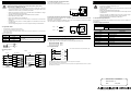
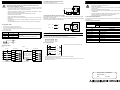
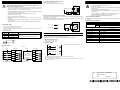
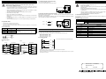
3.3 Diodes and inputs connected in series;
3. Input Wiring
5. Specifications
Vdrop across the diode less than 4V
No more than 2 LEDs should be connected in series.
Wiring cautions
Caution
Observe the following cautions to avoid electrical shock, short-circuit,
disconnection or damage to the unit.
Where input signal lines are used over an extended distance consideration for voltage
drop and noise interference should be made.
•
Twist the end of each stranded cable so that barbed wires are not present.
•
Never solder the end of any cables.
•
Never connect cables of a non permitted size.
Make sure that the number of connected cables is not more than the unit has been
designed for.
•
Fix cables so that any stress is not directly applied on the terminal block or the cable
connection area.
•
The terminal tightening torque is 0.5 to 0.6 Nžm. Tighten securely to avoid malfunction.
• Cleaning and additional tightening of the terminal should only be done after turning OFF
the power supply.
Electric shock is possible while the power is ON.
S/S
• Do not lay signal cable near to high voltage power cable or house them in the same
trunking duct. Effects of noise or surge induction may occur. Keep signal cables a safe
distance of more than 100 mm (4") from these power cables.
•
BX
4.3kΩ
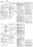
3.4 Resistors and inputs connected in parallel;
Parallel resistance Rp: FX1N-4EX-BD = 15kΩ. If resistance Rp is less than the stated value, then add Rb.
See equation 1 for Rb calculation.
Alternatively; Current leakage: FX1N-4EX-BD= 1.5mA. If the current leakage(I) is greater than the stated
value, then add Rb. See equation 2 for Rb calculation.
Eqn 1 : Rb ≤
Use AWG26-16 for connection with input equipment.
•
The maximum terminal tightening torque is 0.5 to 0.6Nžm.
•
When using a different type of cable, defective contact of the terminal part is possible. Use a crimp terminal to
achieve a good contact.
Sectional area (mm2)
AWG26
0.1288
4Rp
(kΩ)
15 - Rp
6
I - 1.5
Eqn 2 : Rb ≤
•••
•••
AWG16
1.309
Install and uninstall FX1N-4EX-BD after turning OFF the power supply. Installing and
uninstalling while the power supply is ON may cause malfunction.
•
Treat as industrial waste when disposing of the product.
5.1 Environmental specifications
The environmental specifications are equivalent to those of the PLC main unit. (Refer to the manual of the
PLC main unit.)
(kΩ)
Rp
4.3kΩ
BX
4.1 Device allocation
Each input of FX1N-4EX-BD is allocated a special auxiliary relay.
The ON/OFF state of each input is reflected in its corresponding special auxiliary relay.
•
BX0 input of FX1N-4EX-BD
BX1 input of FX1N-4EX-BD
BX2 input of FX1N-4EX-BD
BX3 input of FX1N-4EX-BD
:
:
:
:
Item
Consumption current
4. Device allocation and program example
Terminal processing of wire
•
Rb
Terminal
Stranded cable: Remove sheath, twist core wires, then
connect cable.
Single cable: Remove sheath, then connect cable.
For repair please contact a service representative. Incorrect repair can cause malfunction
or electric shock.
S/S
Linear and sectional area
Linear
•
5.2 Power supply specifications
FX1N-4EX-BD
3.1 Applicable cables
•
• Do not touch the terminals while power is ON.
Electric shock is possible.
FX1N-4EX-BD
M8112
M8113
M8114
M8115
Specification
5V DC
Supply by PLC.
24V DC
25mA or less. Supply from external power supply.
5.3 INPUT specifications
Item
Specification
Input signal voltage
24V DC +20% -15%
Input signal current
About 5mA/24V DC
Input ON current
3.5mA or more
Input OFF current
1.5mA or less
Input response time
About 10mS
Input signal form
Without voltage contact or opening collector Transistor
Circuit insulation
Photo coupler
Operation display
LED lighting when photo coupler is driven
4.2 Program example
6mm(0.2inches)
• Use a contact instruction for each special auxiliary relay.
3.2 Wiring of input
M8112
M0
Source
Sink
FX1N-4EX-BD
24V DC *1
+
S/S
BX0
M8113
24V DC *1
+
4.3kΩ
M1
FX1N-4EX-BD
M8114
S/S
BX0
Y000
4.3kΩ
M8115
T0
4.3kΩ
BX1
BX2
BX3
4.3kΩ
K100
BX1
4.3kΩ
4.3kΩ
BX2
BX3
4.3kΩ
•
When the END instruction of the program is executed, the input process is completed.
REF (I/O refreshing) instruction cannot be used.
•
When input information on FX1N-4EX-BD is used for the operand of each applied instruction as data, only four bit
data (K1M8112) can be used.
4.3kΩ
.*1 The service power supply of the PLC main unit can be used.
Manual number : JY992D95001
Manual revision : A
Date
: May 2001
HEAD OFFICE : MITSUBISHI DENKI BLDG MARUNOUTI TOKYO 100-8310
HIMEJI WORKS : 840, CHIYODA CHO, HIMEJI, JAPAN
TELEX : J24532 CABLE MELCO TOKYO