1
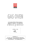
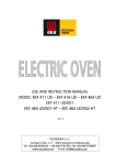
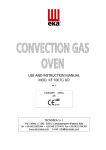
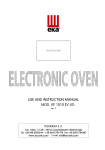
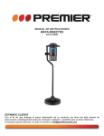
USE AND INSTRUCTION MANUAL
MODD. KF 937 – KF 937 UD
KF 933 – KF 933 U – KF 933 AL – KF 933 AL U
KF 912 – KF 912 IX
KF 965 – KF 965 M – KF 965 AL UD – KF 966 UD
rev. 4
TECNOEKA S.r.l.
Via I. Nievo, n.12/B - 35012 Camposampiero (Padova) Italy
Tel. +39.049.9300344 – +39.049.5791479
+39.049.5791479 Fax +39.049.5794387
www.tecnoeka.com E-mail: [email protected]
_ TECNOEKA Srl _________________________________________________________ use and instruction manual _
Prodotti mirati per Ristorazioni, Pasticcerie,
Panetterie e Gastronomie
TECNOEKA Srl
Via I. Nievo, 12/B
35012 Camposampiero (PD)
Tel. +39 049 5791479 - +39 049 9300344
Fax + 39 049 5794387
www.tecnoeka.com – [email protected]
CE DECLARATION OF CONFORMITY
Annexed document II A, of directive 2006/
2006/42/
42/EC
Manufacturer
Address
TECNOEKA Srl
Via I. Nievo, 12/B - 35012 Camposampiero (Pd)
Type of product
Models
Electric ovens
KF 937 – KF 937 UD – KF 933 – KF 933 U – KF 933 AL – KF 933 AL U
KF 912 – KF 912 IX – KF 965 – KF 965 M – KF 965 AL UD – KF 966 UD
TECNOEKA Srl declares that the above mentioned products conform to the safety
regulations under:
CEI EN 60335-1
- Low voltage directive 2006/95/EC
CEI EN 60335-2-42
- Electromagnetic compatibility Directive 2004/108/EC
CEI EN 55014-1
CEI EN 61000-3-2
CEI EN 61000-3-3
- Machine Directive 2006/42/ EC;
- Directive on the general safety of products 2001/95/ EC;
- Directive on the restriction in the use of dangerous substances in electrical and
electronic appliances 2002/95/ EC;
- Directive on waste from electrical and electronic appliances 2002/96/ EC.
Camposampiero, 17/02/2012.
_________________________________
_________________________________
Signature of a Representative of the Board of directors
X:\Sgq\PRODOTTI\Fam. 1 - FORNI\FORNO ELETTRICO\LEka\MANUALI D'USO - Forno Elettrico
40 60 90 - LEka\Lingua Inglese\Instruction manual KF 937-KF937UD-KF933-KF933UKF933AL-KF933AL_U-KF912-KF912IX-KF965-KF965M-KF965AL_UD-KF966UD - GB - rev.
4.doc
_ page 2 _________________________________________________________________________________________
_ Electric Ovens _ rev. 4__________________ KF 937 – KF 937 UD – KF 933 – KF 933 U – KF 933 AL – KF 933 AL U
KF 912 - KF 912 IX – KF 965 – KF 965 M – KF 965 AL UD – KF 966 UD _
Index
1. Technical service
2. General warnings
3. Technical specifications
4. Instructions for the installer
5. Use instructions (for the user)
6. Residual risks (for
(for the user)
7. How to use the control panel
8. Oven cooking
9. Cooking advice
10. Routine cleaning and maintenance
11. Technical assistance
12. Informations to the consumers
13. Wiring layouts
layouts
14. The Warranty
_________________________________________________________________________________________ page 3 _
_ TECNOEKA Srl _________________________________________________________ use and instruction manual _
1. Technical service
A technical check-up once or twice a year helps prolong the life of the appliance and
guarantees better operation.
Make sure that assistance is carried out solely and exclusively by qualified personnel.
For any spare parts orders or for any information about the appliance, always mention the
serial number and model (data indicated on the "technical data" plate at the rear of the oven).
2. General warnings
Very important!: keep this instruction book together with the appliance for future
consultation.
These warnings were drafted for your safety and for that of others. Please read them carefully
before installing or using the appliance:
- If, on receipt of the goods, the packaging is damaged, write the following on the delivery
note: “I REVERSE THE RIGHT TO CONTROL THE GOODS”,
GOODS” specify the damage and get the
driver to sign in acceptance; send a claim in writing to the seller within 4 calendar days
from the date of receipt. No claim shall be accepted after such period.
- The warehouse inside temperature must not be lower than -9°C; otherwise, the
thermostat (regulation and safety thermostat) control devices of the machine will be
damaged. Failure to observe this prohibition invalidates any responsibility of the
manufacturer of the machine.
- The appliance is intended for professional use and must be utilised by qualified personnel
trained to use it.
- Any modification which may be necessary on the electrical system to enable installation of
the appliance, must be carried out solely by competent personnel.
- It is dangerous to modify or attempt to modify the characteristics of this appliance.
- Never clean the appliance with direct water jets, because, if any water enters, it could limit
the machine's safety .
- Before doing any maintenance or cleaning jobs, disconnect the appliance from the
electrical mains and allow it to cool.
- When the tilting door is wide open, do not put anything on the surface, because the door
hinges could be irreparably damaged.
- Do not attempt to carry out the periodic controls or any repairs by yourself. Contact the
nearest Service Centre and use only original spare parts.
N.B.: Improper or incorrect use and failure to observe the installation instructions shall release the
manufacture from all responsibility. In this connection, the directives in the "POSITIONING"
paragraph must be strictly
strictly observed.
3. Technical specifications
Appliance
model
KF 937
KF 937 UD
KF 933
KF 933
933 U
KF 933 AL
KF 933 AL U
KF 912
KF 912 IX
KF 965
KF 965 AL UD
KF 966 UD
KF 965
965 M
Cooking chamber
Vol.
(dm³=It)
Convection heating
element
(kW)
Grill heating
element
(kW)
Top and bottom
heatel
(kW)
Motorised convection
convection
ventilator
(W)
60
3,5
/
/
120
87
3,0
/
/
120
93
1,6
/
/
50
91
3,0
/
/
120
78
3,0
2,5
3,2
120
_ page 4 _________________________________________________________________________________________
_ Electric Ovens _ rev. 4__________________ KF 937 – KF 937 UD – KF 933 – KF 933 U – KF 933 AL – KF 933 AL U
KF 912 - KF 912 IX – KF 965 – KF 965 M – KF 965 AL UD – KF 966 UD _
Appliance model
Max. absorbed power
(kW)
Power supply voltage
(V~)
Class
Power cable diameter
Type of cable
Connecting electric cable
Dimensions of appliance
(mm) LxDxH
Weight of appliance
(Kg)
KF 937
KF 937 UD
KF 933
KF 933 U – KF 933 AL
KF 933 AL U
KF 912
KF 912 IX
KF 965
KF 965
965 AL UD
KF 965 M – KF 966 UD
3,7
6,4
3,4
6,4
3 x 1,5 mm²
mm
380/400 2N
220/230 (50 Hz)
(50Hz)
I (contro la scossa elettrica)
4 x 2,5 mm
3 x 1,5 mm²
mm²
mm
H07RNH07RN-F
Type Y
790x665x505
790x665x635
900x680x57
0x680x570
900x680x5
900x680x57
0x680x570 (KF 965 ..)
790x665x635 (KF 966 UD)
45
61/62/58/59
61/62/58/59
53
58/56/6
58/56/60
/60/56
220/230
(50 Hz)
380/400 2N
(50Hz)
4 x 2,5 mm²
mm
The noise level of the appliance in operation is below 70 dB (A).
The "technical data" plate is positioned on the rear panel of the appliance.
4. Instructions for the installer
The following instructions are aimed at the qualified installer, to ensure that he carries out the
installation, adjustment and maintenance operations as correctly as possible and according to
current legal regulations. Any operation must be performed with electrical power cut to the
appliance.
Before using the appliance, carefully remove the special adhesive film protecting the parts in
stainless steel. Do not leave any glue residues on the surfaces. If necessary, remove them at once,
with an appropriate solvent.
Fitting the feet - The feet are inside the appliance and must be secured on the four threaded
holes on the base. If necessary, the height of the feet can be adjusted by screwing or unscrewing.
Positioning - Position the appliance perfectly horizontally on a table or similar support (the
table or support must be at least 85 cm above the floor). Position it at a distance of not less than
10 cm from the side and rear walls, to enable natural ventilating air to circulate freely around it.
The appliance is ventilated through specific openings on the metal walls of the outer housing ,
and ensures efficiency and long-life. For this reason it is strictly forbidden to obstruct these
ventilation openings, even partially or for short periods. Failure to observe this specific prohibition
releases the manufacturer of the appliance from
from all responsibility and immediately voids any
guarantee rights for the said appliance, because its constructive conformity has been voluntarily
compromised. Furthermore, the appliance is not suitable for embedding and for grouped
positioning with other identical appliances.
Electrical connection - The appliance must be connected to the electrical mains according to
current legal regulations. Before making the connection, make sure of the following:
- the voltage and frequency values of the power supply system match the values on the
"technical data" plate affixed on the appliance;
- the limiting valve and the system are able to support the appliance's load (see the
"technical data" plate);
- the power supply system has an adequate earth connection according to cu
current
rrent legal
regulations;
- a omnipolar switch with minimum between-contacts aperture of the overvoltage category
III (4000 V), sized to the load and conforming to current legal regulations, is fitted
between the appliance and the mains in the direct connection to the mains;
- the omnipolar switch used for connection is easy to reach when the appliance is installed;
- the yellow/green earth wire is not interrupted by the switch;
- the power supply, when the appliance is operating, must not deviate from the rated
voltage value by ±10%;
_________________________________________________________________________________________ page 5 _
_ TECNOEKA Srl _________________________________________________________ use and instruction manual _
-
make sure that after inserting the power supply cord into the terminal block it does not
come into contact with any of the cooking range's hot parts.
- if the supply cable is damaged then it must be replaced by the manufacturer or by your
technical support or by a qualified person to avoid any risk.
Connection to the water mains - The appliance must be fed with softened drinking water,
with hardness from 0.5°F to 5°F (it is obligatory to use a softener to reduce the formation of lime
inside the cooking chamber) and pressure in the range from 150 to 250 kPa (1.5 - 2.5 bar).
Connection to the water mains should be made through the threaded 3/4" solenoid-valve on
the rear (on the bottom) of the appliance, fitting in between a mechanical filter and an on/off tap
(before you connect the filter, allow a certain quantity of water to flow out in order to drain any
waste from the pipe).
Connecting the power cable - To access the terminal board, just remove the appliance's rear
side-panel. Loosen the cable gripper and allow the cable to pass through it. Arrange the
conductors so that the earth conductor is the last to detach from its terminal if the cable goes
into a state of faulty traction. Connect the phase conductors to the terminals marked “L1” and
“L2”,
“L2” connecting the neutral conductor to the terminal marked "N" and the earth conductor to
the terminal marked with the symbol
according to the following lay-out:
(this electrical connection lay-out is located near the power supply terminal board ). Tighten the
cable gripper and re-fit the rear side-panel of the appliance.
The appliance must be connected to an equipotential system whose efficiency must first be
checked according to current legal regulations.
This connection must be made between different appliances by using the appropriate terminal
marked with the symbol . The equipotential conductor must have a minimum diameter of 2,5
mm2 The equipotential terminal is at the rear of the appliance.
Safety thermal breaker
breaker - The appliance has a manually reset safety thermal breaker. It protects
against excessive dangerous over-temperatures which could be accidentally generated inside the
appliance. This device is located on the back of the oven.
5. Use instructions (for the user)
This appliance is not intended for use by persons (including children) with reduced phycal,
sensory or mental capabilities, or lack of experience and knowledge. Unless they have beengiven
supervision or instruction concerning use of appliance by a person responsible for their safety.
Children should be supervised to ensure that they do not play with the appliance.
For first use, we advise you to let the appliance to run load-free at maximum temperature for
about one hour. In this way, any unpleasant smells due to thermal insulation and residual work
grease are eliminated.
This appliance must be used solely for the purpose for which it was expressly designed, i.e.
cooking foods in the oven. Any other use is considered unsuitable.
The appliance can be used: for all oven cooking of deserts, pizzas, meat, fish, vegetables, as
well as for gratinating, and for re-conditioning cooled and frozen foods.
When placing food in the cooking compartment, leave a space of at least 40 mm between
pans in order not to over-obstruct air circulation.
_ page 6 _________________________________________________________________________________________
_ Electric Ovens _ rev. 4__________________ KF 937 – KF 937 UD – KF 933 – KF 933 U – KF 933 AL – KF 933 AL U
KF 912 - KF 912 IX – KF 965 – KF 965 M – KF 965 AL UD – KF 966 UD _
Do not use pans with higher than necessary edges: edges are barriers which prevent the
circulation of hot air.
Warm up the oven before every cooking operation to obtain maximum uniformity.
Do not salt foods in the cooking compartment.
6. Residual risks (for the user)
After a cooking operation, open the door cautiously, to avoid a violent outflow of heat which
could cause burns.
While the oven is in operation, pay attention to the hot zones (marked on the appliance) of its
external surfaces.
Place the machine on a bench or similar support, at a height of at least 85 cm from the floor.
The bench or support must be able to support the weight of the machine and house it
correctly.
The appliance contains electrical parts and must never be washed with a jet of water or steam.
The appliance is electrically connected: before attempting any cleaning operation, cut power
to the appliance.
To prevent incorrect connection of the appliance, the relevant electrical and water connections
are marked by identification plates.
Do not use the door handle to move the appliance (the glass panel may break).
When the tilting door is wide open, do not use the internal surface to place objects to avoid
damaging permanently the door hinges.
7. How to use the control panel
KF 965
965 M
KF 912 – KF 912 IX
KF 965
KF 965 AL UD
1. Control thermostat
knob
2. Functions selector
knob
3. "End of cooking"
programming knob
4. Humidifier key
5. Line switch key
(ON/OFF Key)
6. Control thermostat
indicator light
7. "End of cooking"
programmer
indicator light
8. Power line indicator
light
KF 937 - KF 937 UD - KF 933 - KF 933 U - KF 933 AL - KF 933 AL U - KF 966 UD
_________________________________________________________________________________________ page 7 _
_ TECNOEKA Srl _________________________________________________________ use and instruction manual _
(Humidifier key
only for Modd. KF 937 UD
KF 933U – KF 933 AL U – KF 966 UD)
Fig. 1
Fig. 2
Fig. 3
Programming cooking time - To run the oven, turn the programmer knob (Fig. 1) in line with
symbol
(continuous operation) or in line with the selected cooking time (up to 120 minutes). In
the second case, end of cooking is signalled by the oven switching OFF automatically.
Programming cooking temperature - Turn the knob of the adjustment thermostat (Fig. 2) in
line with the temperature selected for cooking.
Line key (ON/OFF) - To electrically power up the appliance, press the key of the line switch to
"ON". In this state, the oven is ready to operate.
Humidifier
Humidifier key - To produce vapour inside the oven while the oven is operating and the
chamber is hot, press the key (commanding the humidifier) for a few seconds.
Control thermostat indicator light - The control thermostat orange indicator light goes OFF
whenever the programmed temperature is reached inside the cooking compartment. It lights up
again when the thermostat is tripped to re-establish this temperature.
"End of cooking" programmer indicator light - The programmer orange indicator light indicate
that the oven is operating and that cooking time is active.
Line indicator light - The green line-indicator light indicates that the oven is electrically
connected to the power supply line.
Oven internal light - The light is always on when the oven is operating.
To switch off the oven - Turn OFF the knobs of the "end of cooking" programmer and of the
thermostat and press the line switch key to "OFF". When you have finished using the oven, shut
off the water ON/OFF tap upstream of the appliance and cut out electric power.
8. Oven cooking
For cooking, before putting food in, warm up the oven to the required temperature. When the
oven reaches the temperature, put the food in and check cooking time. Switch off the oven 5
minutes before the theoretical time in order to recover stored heat.
MODD. KF 937 – KF 933 – KF 933 AL
Convection cooking - Activate the oven and turn the thermostat knob in line with the required
temperature.
Defreezing - Activate the oven and turn the thermostat knob to the OFF position.
MODD. KF 937 UD - KF 933 U - KF 933 AL U - KF 912 - KF 912 IX - KF 965 - KF 965 AL UD - KF 966 UD
Convection cooking - Activate the oven and turn the thermostat knob in line with the required
temperature.
Defreezing - Activate the oven and turn the thermostat knob to the OFF position.
Humidification (no for this models. KF 937 – KF 933 – KF 933 AL) While the oven is functioning
press the humidification botton to generate steam in the already heated cooking chamber.
_ page 8 _________________________________________________________________________________________
_ Electric Ovens _ rev. 4__________________ KF 937 – KF 937 UD – KF 933 – KF 933 U – KF 933 AL – KF 933 AL U
KF 912 - KF 912 IX – KF 965 – KF 965 M – KF 965 AL UD – KF 966 UD _
MOD. KF 965 M
Traditional cooking - Switch on the oven. Turn the knob of the functions selector (Fig. 3) to
symbol
and the thermostat knob in line with the required temperature If you want a different
temperature at the top or bottom, turn the functions selector knob in line with the symbol
or
.
Cooking with the grill - Switch on the oven. Turn the functions selector knob to
and the
thermostat knob in line with the required temperature (IMPORTANT
IMPORTANT: grill cooking must be done
with the oven door closed).
Cooking with the ventilated grill - Switch on the oven. Turn the functions selector knob to
symbol
and the thermostat knob in line with the required temperature (IMPORTANT
IMPORTANT: grill
cooking must be done with the oven door closed).
Ventilated traditional cooking - Switch on the oven. Turn the functions selector knob to
symbol
and the thermostat knob in line with the required temperature.
Convection cooking - Switch on the oven. Turn the functions selector knob to symbol
and
the thermostat knob in line with the required temperature.
Defreezing - Switch on the oven. Turn the functions selector knob to symbol
and the
thermostat knob to its OFF position.
Humidification - While the oven is functioning press the humidification botton to generate
steam in the already heated cooking chamber.
9. Cooking advice
Traditional
Traditional cooking - Heat is supplied from above and below and, therefore, it is preferable to
use the central guides. If cooking requires extra heat from above and below, use the top or
bottom guides.
Convection cooking - Heat is transferred to the foods by pre-heated air, forced to circulate by
in the cooking chamber. The heat quickly and uniformly reaches all parts of the chamber,
enabling simultaneous cooking of different types of food (providing they have the same cooking
temperature), placed on the shelves without mixing tastes and smells. Convection cooking is
particularly convenient for rapid defreezing, and for sterilising preserves and drying mushrooms
and fruit.
Cooking with the grill - Grilling is effected by the thermal radiation of an incandescent
electrical heating-element. The temperature produced by the infra-red rays is very high and oneway (downward from above), and, therefore, food surfaces are immediately browned.
Cooking with the ventilated grill - Forced circulation of air is combined with thermal radiation
produced by the grill, and this allows heat to gradually penetrate the inside of the food without
burning the surface.
Cooking desserts - Desserts require a very high temperature (usually from 150 to 200°C) and a
pre-heated oven (about ten minutes). The oven door must not be opened until at least 3/4 of the
cooking time has elapsed. Whipped dough must be difficult to detach from a spoon because
excessive fluidity would prolong cooking time to no avail.
Cooking meat - Meat to be cooked should weight at least 1 Kg to prevent it drying too much.
Very tender red meats to be cooked rare, which must be cooked on the outside to keep all their
gravy, require short cooking time at high temperature (200-250°C). The gravy ingredients must
be placed immediately in the pan only if the cooking temperature is brief, otherwise they should
be added during the last half-hour. You can check the degree of cooking by squashing the meat
with a spoon: if the meat does not yield, it is correctly cooked. For roast beef and fillet, which
must remain pink inside, cooking time must be very brief. Meats may be placed on a plate
_________________________________________________________________________________________ page 9 _
_ TECNOEKA Srl _________________________________________________________ use and instruction manual _
suitable for oven cooking or directly on the grill, under which you should place a tray to collect
the gravy. When cooking has finished, we advise you to wait for 15 minutes before cutting the
meat so that the gravy does not come out. Before being served, the dishes may be kept hot in
the oven at minimum temperature.
Grilling - Almost all meats may be grilled, with the exception of some lean game meats and
meat loaves. Apply a little oil on the meat or fish to be cooked and always place them on the grill
- put the grill in the guides nearest or furthest from the grill heating element in proportion to the
meat, in order to avoid burning the surface and cooking the inside insufficiently. It is useful to
place a tray under the grill to collect drops of gravy and fat.
10. Routine cleaning and maintenance
(WARNING: Cut power to the appliance before every operation)
General cleaning - Clean the oven when it is cold. Wash enamelled parts with lukewarm water
and soap, do not use abrasive products, steel wool, or acids, which could ruin them. To clean the
steel parts, do not use products containing chlorine (sodium hypochlorite, hydrochloric acid, etc)
even if diluted. Use specific off-the-shelf products or a little hot vinegar. Rinse thoroughly with
water and dry with a soft cloth. Clean the glass door of the oven with hot water only, and do not
use rough cloths. Do not allow foods (especially acid foods such as salt, vinegar, lemon, etc) to
stagnate on the stainless steel parts, because they could deteriorate. Do not wash the appliance
with direct jets of water, because if water enters, this could limit the appliance's safety. Do not
use corrosive substances (e.g. hydrochloric acid) to clean the oven' s support bench.
Cleaning the oven - It is good practice to clean the oven interior at the end of every day of
duty. In this way it will be easier to remove cooking residues, preventing them from burning
when the oven is next used. Clean it accurately with hot water and soap or with the appropriate
off-the-shelf products.
Cleaning the oven door (except MODD. KF 933 AL - KF 933 AL U - KF 937 UD - KF 965 AL UD
- KF 966 UD) - To clean the oven door thoroughly, proceed as follows:
- fully open the door;
- attach the rings “A” onto the hinge seats (Fig. 4);
- lift the door gently and withdraw it (Fig. 5).
Fig. 4
Fig. 5
Fig. 6
(MODD.
(MODD. KF 937 UD – KF 966 UD)
- To clean the oven door thoroughly, proceed as follows:
- fully open the door;
- insert the equipped plugs in the “A” holes on the hinges (Fig. 7);
- lift the door gently and withdraw it (Fig. 8);
- put back the door in the initial position by operating inverserly.
_ page 10 _________________________________________________________________________________________
_ Electric Ovens _ rev. 4__________________ KF 937 – KF 937 UD – KF 933 – KF 933 U – KF 933 AL – KF 933 AL U
KF 912 - KF 912 IX – KF 965 – KF 965 M – KF 965 AL UD – KF 966 UD _
A
Fig. 7
Fig. 8
Replacing oven lamp - Electrically switch off the appliance; unscrew the protective glass cap
(Fig. 6);
(except MODD. KF 937 UD – KF 965 AL UD – KF 966 UD) unscrew the lamp and replace it
with another lamp suitable for high temperatures (300°C), with the following characteristics:
- Voltage
230/240 V
15 W
- Power
- Fitting
E 14
Refit the glass cap and power up the appliance.
(Only for the models KF 937 UD – KF 965 AL UD – KF 966 UD) remove the faulty halogen lamp
and insert the new one by using paper or cloth to not touch the lamp with bare hands.
Please note that the new halogen lamp must have the same characteristics as the one removed.
Put back the lamp cover with the gaskets and turn on the electricity.
11.
11. Technical assistance
Before leaving the factory, the appliance was completely regulated and tested by expert
specialised personnel to guarantee the best operating results.
All repairs and settings must be performed with utmost care and attention, respecting national
safety regulations in force. Always contact your retailer or our nearest Service Centre, giving
details of the problem, the appliance model and the serial number (on the rating plate on the
rear panel).
For any maintenance the user can contact Tecnoeka by calling the telephone numbers on the
cover or going to www.tecnoeka.com.
www.tecnoeka.com
12. Informations to the consumers
Further to Directive 2002/96/EC, the symbol of the crossed rubbish skip on
the appliance means that at the end of its life, the product must be disposed
of separately from the other rubbish. The user must hand the appliance to a
specialised waste collection centre for electric and electronic equipment.
The separate collection of the rubbish and subsequent treatment, recovery and disposal help to
produce other equipment using recycled materials, reducing the negative effects on the
environment and public health, which would be caused by incorrect management of the
rubbish.
Should the user dispose of the product abusively, administrative sanctions would be applied.
_________________________________________________________________________________________ page 11 _
_ TECNOEKA Srl _________________________________________________________ use and instruction manual _
13. Wiring layouts
MOD. KF 937
Key
M
P
MI
T1
T2
R
L1-L2
Power terminal board
"End of cooking" programmer
Door microswitch
Safety thermostat
Control thermostat
Circular heating-element
Lighting lamps
V
C
IM
B
S1
S2
Radial motoventilator
Capacitor
Operating direction reversing element
Contactor coil
Power line indicator light
Thermostat indicator light
_ page 12 _________________________________________________________________________________________
_ Electric Ovens _ rev. 4__________________ KF 937 – KF 937 UD – KF 933 – KF 933 U – KF 933 AL – KF 933 AL U
KF 912 - KF 912 IX – KF 965 – KF 965 M – KF 965 AL UD – KF 966 UD _
MOD. KF 937 UD
Key
M
P
MI
T1
T2
IU
EV
L1-L2
Power terminal board
"End of cooking" programmer
Door microswitch
Safety thermostat
Control thermostat
Humidifier switch
Humidifier solenoid-valve
Lighting lamps
R1
V
C
IM
B
S1
S2
Circular heating-element
Radial motoventilator
Capacitor
Operating direction reversing element
Contactor coil
Power line indicator light
Thermostat indicator light
_________________________________________________________________________________________ page 13 _
_ TECNOEKA Srl _________________________________________________________ use and instruction manual _
MODD
ODD. KF 933 – KF 933 AL
Key
M
P
MI
T1
T2
R1-R2
L1-L2
Power terminal board
"End of cooking" programmer
Door microswitch
Safety thermostat
Control thermostat
Circular heating-elements
Lighting lamps
V1-V2
C1-C2
IM
B
S1
S2
Radial motoventilators
Capacitors
Operating direction reversing element
Contactor coil
Programmer indicator light
Thermostat indicator light
MODD
MODD. KF 933 U – KF 933 AL U
Key
M
P
MI
T1
T2
EV
IU
L1-L2
Power terminal board
"End of cooking" programmer
Door microswitch
Safety thermostat
Control thermostat
Humidifier solenoid-valve
Humidifier switch
Lighting lamps
R1-R2 Circular heating-elements
V1-V2
Radial motoventilators
C1-C2
Capacitors
IM
Operating direction reversing element
B
Contactor coil
S1
Programmer indicator light
S2
Thermostat indicator light
_ page 14 _________________________________________________________________________________________
_ Electric Ovens _ rev. 4__________________ KF 937 – KF 937 UD – KF 933 – KF 933 U – KF 933 AL – KF 933 AL U
KF 912 - KF 912 IX – KF 965 – KF 965 M – KF 965 AL UD – KF 966 UD _
MODD. KF 912 – KF 912 IX
Key
M
P
MI
T1
T2
IU
IL
L1-L2
Power terminal board
"End of cooking" programmer
Door microswitch
Safety thermostat
Control thermostat
Humidifier switch
Power line switch
Lighting lamps
R1-R2
V1-V2
EV
B
S1
S2
S3
Circular heating elements
Radial motoventilators
Water solenoid-valve
Contactor coil
Power line indicator light
Programmer indicator light
Thermostat indicator light
_________________________________________________________________________________________ page 15 _
_ TECNOEKA Srl _________________________________________________________ use and instruction manual _
MOD. KF 965
Key
M
P
MI
T1
T2
IU
R1-R2
IL
L1-L2
Power terminal board
"End of cooking" programmer
Door microswitch
Safety thermostat
Control thermostat
Humidifier switch
Circular heating elements
Power line switch
Lighting lamps
V1-V2
EV
B
S1
S2
S3
C1-C2
IM
Radial motoventilators
Water solenoid-valve
Contactor coil
Power line indicator light
Programmer indicator light
Thermostat indicator light
Capacitors
Operating direction reversing element
_ page 16 _________________________________________________________________________________________
_ Electric Ovens _ rev. 4__________________ KF 937 – KF 937 UD – KF 933 – KF 933 U – KF 933 AL – KF 933 AL U
KF 912 - KF 912 IX – KF 965 – KF 965 M – KF 965 AL UD – KF 966 UD _
MOD. KF 965 AL UD
Key
M
P
MI
T1
T2
IU
R1-R2
IL
L1
Power terminal board
"End of cooking" programmer
Door microswitch
Safety thermostat
Control thermostat
Humidifier switch
Circular heating elements
Power line switch
Lighting lamps
V1-V2
EV
B
S1
S2
S3
C1-C2
IM
Radial motoventilators
Water solenoid-valve
Contactor coil
Power line indicator light
Programmer indicator light
Thermostat indicator light
Capacitors
Operating direction reversing element
_________________________________________________________________________________________ page 17 _
_ TECNOEKA Srl _________________________________________________________ use and instruction manual _
MOD. KF 965 M
Key
M
P
MI
T1
T2
IU
C
R1-R2
R3
R4
R5
Power terminal board
"End of cooking" programmer
Door microswitch
Safety thermostat
Control thermostat
Humidifier switch
Switch
Circular heating elements
Grill heating element
Lower heating element
Upper heating element
L1-L2
V1-V2
E
B1
B-B2
S1
S2
S3
C1-C2
IM
Lighting lamps
Radial motoventilators
Humidifier solenoid-valve
Contactor coil
Relay coil
Power line indicator light
Programmer indicator light
Thermostat indicator light
Capacitors
Operating direction reversing element
_ page 18 _________________________________________________________________________________________
_ Electric Ovens _ rev. 4__________________ KF 937 – KF 937 UD – KF 933 – KF 933 U – KF 933 AL – KF 933 AL U
KF 912 - KF 912 IX – KF 965 – KF 965 M – KF 965 AL UD – KF 966 UD _
MOD. KF 966
966 UD
Key
M
P
MI
T1
T2
R1-R2
EV
IU
Power terminal board
"End of cooking" programmer
Door microswitch
Safety thermostat
Control thermostat
Circular heating elements
Humidifier solenoid-valve
Humidifier switch
V1-V2
C1-C2
IM
B
S1
S2
L
Radial motoventilators
Capacitors
Operating direction reversing element
Contactor coil
Programmer indicator light
Thermostat indicator light
Lighting lamp
_________________________________________________________________________________________ page 19 _
_ TECNOEKA Srl _________________________________________________________ use and instruction manual _
14. The Warranty
Your appliance is covered by warranty. The seller will replace or repair (and his decision will be final),
free of charge for the customer, only those parts that are defective due to a manufacturing fault on
condition that, under penalty of forfeiture:
− for domestic equipment, the customer notifies the fault within two months from the date when
he/she discovered it and anyway within 2 years form the date of purchase;
− for professional equipment, the customer notifies the fault within 8 days from the date when
he/she discovered it and anyway within 12 months from the date of purchase,
by registered letter with acknowledgement of receipt and enclosing the invoice or receipt proving the
purchase.
Apart from the case when the customer cannot produce the invoice or receipt proving the purchase or
when the above-mentioned terms are not complied with, the warranty is expressly excluded in the
following cases:
1) faults or breakage caused by the transport;
2) wrong or incorrect installation of the product (for instance because of insufficient draught of the
flue or exhausts) in light of the instructions given in the user’s handbook supplied with the
product;
3) inadequate or abnormal electrical, hydraulic and/or gas supplies;
4) carelessness, negligence or incompetence in using the product in light of the instructions given in
the user’s handbook supplied with the product;
5) use of the product for uses different from the one for which it was built or anyway in a manner
not compliant with the instructions given in the user’s handbook supplied with the product;
6) tampering with the product;
7) adjustments and/or maintenance and/or repairs carried out by unauthorised personnel and/or with
non original spare parts;
8) inadequate or careless maintenance of the product in contrast with the user’s handbook supplied
with the product;
9) damages caused by fire, natural disasters and accident as well as by any cause not attributable to
TECNOEKA SRL.
The warranty explicitly excludes:
excludes varnished or enamelled parts, knobs, handles, movable or removable
plastic parts, bulbs, glass parts, refractories and any accessories.
TECNOEKA SRL cannot be held responsible for any damages, either direct or indirect, caused by the
product breaking down or following its non-use.
Any repairs carried out during the warranty do not cause said warranty to be extended or renewed.
Nobody is authorised to modify the terms and conditions of the warranty or to issue new verbal or written
warranties.
The warranty is valid only for appliances installed
installed in the European Union.
Any dispute shall be settled by the competent Court in Padua.
Warning for the Buyer:
1. the cooking appliance is designed only for cooking purposes while the heating appliance is
designed only for heating domestic environments;
2. TECNOEKA S.r.l. does not install the appliances; the seller shall be responsible for any installation
carried out;
3. TECNOEKA S.r.l. cannot be held responsible for any damages, either direct or indirect, to people,
pets or property caused by the appliance breaking down or following its non-use.
The Manufacturer cannot be held responsible for any inaccuracies due to misprints or mistakes in copying
in this handbook. The Manufacturer reserves the right to modify the products as he deems fit, also in the
interest of the user, without affecting the vital characteristics of functionality and safety.
_ page 20 _________________________________________________________________________________________