1
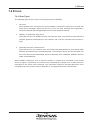
To our customers,
Old Company Name in Catalogs and Other Documents
On April 1st, 2010, NEC Electronics Corporation merged with Renesas Technology
Corporation, and Renesas Electronics Corporation took over all the business of both
companies. Therefore, although the old company name remains in this document, it is a valid
Renesas Electronics document. We appreciate your understanding.
Renesas Electronics website: http://www.renesas.com
April 1st, 2010
Renesas Electronics Corporation
Issued by: Renesas Electronics Corporation (http://www.renesas.com)
Send any inquiries to http://www.renesas.com/inquiry.
Notice
1.
2.
3.
4.
5.
6.
7.
All information included in this document is current as of the date this document is issued. Such information, however, is
subject to change without any prior notice. Before purchasing or using any Renesas Electronics products listed herein, please
confirm the latest product information with a Renesas Electronics sales office. Also, please pay regular and careful attention to
additional and different information to be disclosed by Renesas Electronics such as that disclosed through our website.
Renesas Electronics does not assume any liability for infringement of patents, copyrights, or other intellectual property rights
of third parties by or arising from the use of Renesas Electronics products or technical information described in this document.
No license, express, implied or otherwise, is granted hereby under any patents, copyrights or other intellectual property rights
of Renesas Electronics or others.
You should not alter, modify, copy, or otherwise misappropriate any Renesas Electronics product, whether in whole or in part.
Descriptions of circuits, software and other related information in this document are provided only to illustrate the operation of
semiconductor products and application examples. You are fully responsible for the incorporation of these circuits, software,
and information in the design of your equipment. Renesas Electronics assumes no responsibility for any losses incurred by
you or third parties arising from the use of these circuits, software, or information.
When exporting the products or technology described in this document, you should comply with the applicable export control
laws and regulations and follow the procedures required by such laws and regulations. You should not use Renesas
Electronics products or the technology described in this document for any purpose relating to military applications or use by
the military, including but not limited to the development of weapons of mass destruction. Renesas Electronics products and
technology may not be used for or incorporated into any products or systems whose manufacture, use, or sale is prohibited
under any applicable domestic or foreign laws or regulations.
Renesas Electronics has used reasonable care in preparing the information included in this document, but Renesas Electronics
does not warrant that such information is error free. Renesas Electronics assumes no liability whatsoever for any damages
incurred by you resulting from errors in or omissions from the information included herein.
Renesas Electronics products are classified according to the following three quality grades: “Standard”, “High Quality”, and
“Specific”. The recommended applications for each Renesas Electronics product depends on the product’s quality grade, as
indicated below. You must check the quality grade of each Renesas Electronics product before using it in a particular
application. You may not use any Renesas Electronics product for any application categorized as “Specific” without the prior
written consent of Renesas Electronics. Further, you may not use any Renesas Electronics product for any application for
which it is not intended without the prior written consent of Renesas Electronics. Renesas Electronics shall not be in any way
liable for any damages or losses incurred by you or third parties arising from the use of any Renesas Electronics product for an
application categorized as “Specific” or for which the product is not intended where you have failed to obtain the prior written
consent of Renesas Electronics. The quality grade of each Renesas Electronics product is “Standard” unless otherwise
expressly specified in a Renesas Electronics data sheets or data books, etc.
“Standard”:
8.
9.
10.
11.
12.
Computers; office equipment; communications equipment; test and measurement equipment; audio and visual
equipment; home electronic appliances; machine tools; personal electronic equipment; and industrial robots.
“High Quality”: Transportation equipment (automobiles, trains, ships, etc.); traffic control systems; anti-disaster systems; anticrime systems; safety equipment; and medical equipment not specifically designed for life support.
“Specific”:
Aircraft; aerospace equipment; submersible repeaters; nuclear reactor control systems; medical equipment or
systems for life support (e.g. artificial life support devices or systems), surgical implantations, or healthcare
intervention (e.g. excision, etc.), and any other applications or purposes that pose a direct threat to human life.
You should use the Renesas Electronics products described in this document within the range specified by Renesas Electronics,
especially with respect to the maximum rating, operating supply voltage range, movement power voltage range, heat radiation
characteristics, installation and other product characteristics. Renesas Electronics shall have no liability for malfunctions or
damages arising out of the use of Renesas Electronics products beyond such specified ranges.
Although Renesas Electronics endeavors to improve the quality and reliability of its products, semiconductor products have
specific characteristics such as the occurrence of failure at a certain rate and malfunctions under certain use conditions. Further,
Renesas Electronics products are not subject to radiation resistance design. Please be sure to implement safety measures to
guard them against the possibility of physical injury, and injury or damage caused by fire in the event of the failure of a
Renesas Electronics product, such as safety design for hardware and software including but not limited to redundancy, fire
control and malfunction prevention, appropriate treatment for aging degradation or any other appropriate measures. Because
the evaluation of microcomputer software alone is very difficult, please evaluate the safety of the final products or system
manufactured by you.
Please contact a Renesas Electronics sales office for details as to environmental matters such as the environmental
compatibility of each Renesas Electronics product. Please use Renesas Electronics products in compliance with all applicable
laws and regulations that regulate the inclusion or use of controlled substances, including without limitation, the EU RoHS
Directive. Renesas Electronics assumes no liability for damages or losses occurring as a result of your noncompliance with
applicable laws and regulations.
This document may not be reproduced or duplicated, in any form, in whole or in part, without prior written consent of Renesas
Electronics.
Please contact a Renesas Electronics sales office if you have any questions regarding the information contained in this
document or Renesas Electronics products, or if you have any other inquiries.
(Note 1) “Renesas Electronics” as used in this document means Renesas Electronics Corporation and also includes its majorityowned subsidiaries.
(Note 2) “Renesas Electronics product(s)” means any product developed or manufactured by or for Renesas Electronics.
To all our customers
Regarding the change of names mentioned in the document, such as Mitsubishi
Electric and Mitsubishi XX, to Renesas Technology Corp.
The semiconductor operations of Hitachi and Mitsubishi Electric were transferred to Renesas
Technology Corporation on April 1st 2003. These operations include microcomputer, logic, analog
and discrete devices, and memory chips other than DRAMs (flash memory, SRAMs etc.)
Accordingly, although Mitsubishi Electric, Mitsubishi Electric Corporation, Mitsubishi
Semiconductors, and other Mitsubishi brand names are mentioned in the document, these names
have in fact all been changed to Renesas Technology Corp. Thank you for your understanding.
Except for our corporate trademark, logo and corporate statement, no changes whatsoever have been
made to the contents of the document, and these changes do not constitute any alteration to the
contents of the document itself.
Note : Mitsubishi Electric will continue the business operations of high frequency & optical devices
and power devices.
Renesas Technology Corp.
Customer Support Dept.
April 1, 2003
User’s Manual
RASM77 V.5.10
User’s Manual
Relocatable Assembler for 77xx Series
Rev.1.00 2003.08
z Microsoft, MS-DOS, Windows, and Windows NT are registered trademarks of Microsoft Corporation in the U.S. and other countries.
z Sun, Java and all Java-based trademarks and logos are trademarks or registered trademarks of Sun Microsystems, Inc. in the U.S. or
other countries, and are used under license.
z Linux is a trademark of Linus Torvalds.
z Turbolinux and its logo are trademarks of Turbolinux, Inc.
z IBM and AT are registered trademarks of International Business Machines Corporation.
z Intel and Pentium are registered trademarks of Intel Corporation.
z Adobe, Acrobat, and Acrobat Reader are trademarks of Adobe Systems Incorporated.
z All other brand and product names are trademarks, registered trademarks or service marks of their respective holders.
Keep safety first in your circuit designs!
z Renesas Technology Corporation and Renesas Solutions Corporation put the maximum effort into making semiconductor products
better and more reliable, but there is always the possibility that trouble may occur with them. Trouble with semiconductors may lead to
personal injury, fire or property damage. Remember to give due consideration to safety when making your circuit designs, with
appropriate measures such as (i) placement of substitutive, auxiliary circuits, (ii) use of nonflammable material or (iii) prevention
against any malfunction or mishap.
Notes regarding these materials
z These materials are intended as a reference to assist our customers in the selection of the Renesas Technology product best suited to
the customer's application; they do not convey any license under any intellectual property rights, or any other rights, belonging to
Renesas Technology Corporation, Renesas Solutions Corporation or a third party.
z Renesas Technology Corporation and Renesas Solutions Corporation assume no responsibility for any damage, or infringement of any
third-party's rights, originating in the use of any product data, diagrams, charts, programs, algorithms, or circuit application examples
contained in these materials.
z All information contained in these materials, including product data, diagrams, charts, programs and algorithms represents information
on products at the time of publication of these materials, and are subject to change by Renesas Technology Corporation and Renesas
Solutions Corporation without notice due to product improvements or other reasons. It is therefore recommended that customers
contact Renesas Technology Corporation, Renesas Solutions Corporation or an authorized Renesas Technology product distributor
for the latest product information before purchasing a product listed herein. The information described here may contain technical
inaccuracies or typographical errors. Renesas Technology Corporation and Renesas Solutions Corporation assume no responsibility
for any damage, liability, or other loss rising from these inaccuracies or errors. Please also pay attention to information published by
Renesas Technology Corporation and Renesas Solutions Corporation by various means, including the Renesas home page
(http://www.renesas.com).
z When using any or all of the information contained in these materials, including product data, diagrams, charts, programs, and
algorithms, please be sure to evaluate all information as a total system before making a final decision on the applicability of the
information and products. Renesas Technology Corporation and Renesas Solutions Corporation assume no responsibility for any
damage, liability or other loss resulting from the information contained herein.
z Renesas Technology semiconductors are not designed or manufactured for use in a device or system that is used under
circumstances in which human life is potentially at stake. Please contact Renesas Technology Corporation, Renesas Solutions
Corporation or an authorized Renesas Technology product distributor when considering the use of a product contained herein for any
specific purposes, such as apparatus or systems for transportation, vehicular, medical, aerospace, nuclear, or undersea repeater use.
z The prior written approval of Renesas Technology Corporation and Renesas Solutions Corporation is necessary to reprint or reproduce
in whole or in part these materials.
z If these products or technologies are subject to the Japanese export control restrictions, they must be exported under a license from
the Japanese government and cannot be imported into a country other than the approved destination. Any diversion or reexport
contrary to the export control laws and regulations of Japan and/or the country of destination is prohibited.
z Please contact Renesas Technology Corporation or Renesas Solutions Corporation for further details on these materials or the
products contained therein.
For inquiries about the contents of this document or product, fill in the text file the installer generates in the following directory and email
to your local distributor.
¥SUPPORT¥Product-name¥SUPPORT.TXT
Renesas Tools Homepage
http://www.renesas.com/en/tools
Preface
RASM77 is a relocatable assembler for the 7700 Family microcomputers. RASM77 creates machine language data files, debugging information files, etc. from source programs written in 7700
Family assembly language for the 7700 Family microcomputers. This user's manual describes the
functions and operation of the following programs that make up the software product RASM77:
1.
2.
3.
4.
5.
Relocatable assembler RASM77
Structured preprocessor PRE77
Linkage editor LINK77
Librarian LIB77
Cross-referencer CRF77
This manual does not guarantee nor authorize the right to use the software.
Organization of RASM77 User's Manual
The RASM77 User's Manual consists of five parts as described below. Each part describes each of
the five programs that make up RASM77 Assembler in the same sequence as much as possible.
For example, explanation of environment variables for each program can be found in the chapter
that describes operation of that program.
•
Part 1: RASM77 Operation Manual
Describes the method of using the relocatable assembler program RASM77 and the method
of coding source programs.
•
Part 2: PRE77 Operation Manual
Describes method of using preprocessor language.
•
Part 3: LINK77 Operation Manual
Describes method of executing the linker program LINK77 and the functions of its sections.
•
Part 4: LIB77 Operation Manual
Describes the method of using the librarian program LIB77.
•
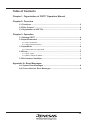
Part 5: CRF77 Operation Manual
Describes the method of using the cross-referencer program CRF77.
i
PART 1
RELOCATABLE MACRO ASSEMBLER
FOR 7700 FAMILY
RASM77 OPERATION MANUAL
Table of Contents
Chapter 1. RASM77 User’s Manual Organization
Chapter 2. Overview
2.1 Functions ................................................................................................ 3
2.2 Files Created by RASM77 ...................................................................... 4
2.3 Structure of PRN File ............................................................................. 4
2.4 Structure of TAG File ........................................................................... 12
Chapter 3. Source Program Coding Method
3.1 Structure of Source Program .............................................................. 13
3.2 Line Formats ......................................................................................... 14
3.2.1 Instruction Line ..................................................................................................... 14
3.2.2 Structured Preprocessor Instruction Line ............................................................. 14
3.2.3 Pseudo Instruction Line ........................................................................................ 14
3.2.4 Macro Instruction Line .......................................................................................... 15
3.2.5 Comment Line ...................................................................................................... 15
3.3 Field Coding Method ............................................................................ 15
3.3.1 Symbol/Label Field ............................................................................................... 15
3.3.2 Op-code/Pseudo Instruction Field ........................................................................ 16
3.3.3 Operand Field ....................................................................................................... 16
3.3.4 Comment Field ..................................................................................................... 16
3.4 Operand Field Coding Method ............................................................ 16
3.4.1 Data Format .......................................................................................................... 16
3.4.2 Instructions ........................................................................................................... 17
Chapter 4. Instruction Coding Method
4.1 Addressing Mode ................................................................................. 19
4.2 Data Length Specification ................................................................... 21
4.3 Setting Direct Page and Absolute Addressing .................................. 23
4.4 Addressing Mode Selection ................................................................ 23
4.4.1 Setting the Direct Page Register and Data Bank Register ................................... 24
4.4.2 Addressing Mode During Symbol•Absolute Value Operation ............................... 25
4.4.3 Addressing Mode During Label Operation ........................................................... 26
4.4.4 Disabling Addressing Mode Selection .................................................................. 28
1-i
Chapter 5. Pseudo Instruction Coding Method
5.1 Function of Pseudo Instructions ........................................................30
5.2 Assembly Control Pseudo Instructions ............................................. 32
5.2.1 Data Length Declaration ....................................................................................... 32
5.2.2 DPR and DT Value Declaration ............................................................................ 32
5.2.3 Conditional Assembly ........................................................................................... 32
5.2.4 Include File ........................................................................................................... 32
5.2.5 Equation ............................................................................................................... 32
5.2.6 Declare End of Assembly ..................................................................................... 32
5.2.7 Message Output ................................................................................................... 33
5.2.8 Assembly Error Output ......................................................................................... 33
5.2.9 Define String ......................................................................................................... 33
5.3 Address Control Pseudo Instructions ................................................ 33
5.3.1 Address Declaration ............................................................................................. 33
5.3.2 Memory Allocation ................................................................................................ 33
5.3.3 Data Definition ...................................................................................................... 33
5.3.4 Correct Address Alignment ................................................................................... 33
5.4 Linkage Control Pseudo Instructions ................................................ 34
5.4.1 Section Name Specification .................................................................................. 34
5.4.2 Global Label Name Specification ......................................................................... 34
5.4.3 Linkage Filename Specification ............................................................................ 34
5.4.4 Version Control ..................................................................................................... 34
5.5 Listing Control Pseudo Instructions ..................................................34
5.6 Source Level Debug Support ..............................................................35
5.7 Reserved Pseudo Instructions ............................................................ 35
Chapter 6. Macro Instruction
6.1 Macro Instruction Functions ............................................................... 36
6.2 Macro Instruction Types ...................................................................... 36
6.3 Macro Operators ...................................................................................37
Chapter 7. Operation
7.1 Starting RASM77 .................................................................................. 41
7.2 Input Parameters .................................................................................. 41
7.2.1 Source Filename .................................................................................................. 41
7.2.2 Command Parameters ......................................................................................... 41
7.3 Input Method .........................................................................................44
7.4 Errors ..................................................................................................... 47
7.4.1 Error Types ........................................................................................................... 47
7.4.2 Return Values to MS-DOS ................................................................................... 49
7.5 Environment variables ......................................................................... 49
1-ii
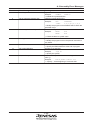
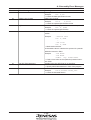
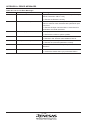
Appendix A. Error Messages
A.1 System Error Messages ...................................................................... 50
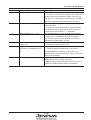
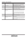
A.2 Assembly Error Messages .................................................................. 52
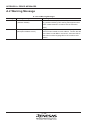
A.3 Warning Messages .............................................................................. 57
Appendix B. Pseudo Instructions
B.1 Conventions ......................................................................................... 59
B.2 Pseudo Instructions ............................................................................ 59
B.3 Debugging Pseudo Instructions ........................................................ 83
B.4 Reserved Pseudo Instructions ........................................................... 87
Appendix C. Macro Instructions
C.1 Conventions ......................................................................................... 93
C.2 Macro Instructions ............................................................................... 93
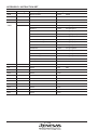
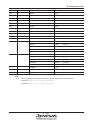
Appendix D. Instruction Set
D.1 Symbols .............................................................................................. 105
D.2 Instruction Set .................................................................................... 107
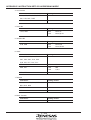
Appendix E. Instruction by Addressing Mode
E.1 Instruction by Addressing Mode ...................................................... 121
E.2 Addressing Mode Relationship Table .............................................. 128
E.3 Selection of Addressing Mode ......................................................... 129
1-iii
List of Figures
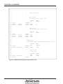
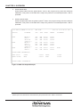
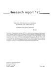
Figure 2.1 PRN File Example (Beginning of Source File) ......................... 6
Figure 2.2 PRN File Example (Middle of Source File) ............................... 7
Figure 2.3 PRN File Example (End of Source File) .................................... 8
Figure 2.4 PRN File Example (Assembly Information) .............................. 8
Figure 2.5 PRN File Example (Symbol and Label List) ............................. 9
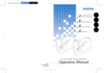
Figure 2.6 PRN File Example (Macro and Include Expansion)............... 10
Figure 2.7 PRN File Example (Structured Preprocessor Section) ......... 11
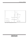
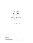
Figure 2.8 TAG File Example ..................................................................... 12
Figure 4.1 Example of conditional assemble
based on data and index lengths ....................... 22
Figure 7.1 Example of RASM77 Startup Command Line ........................ 44
Figure 7.2 HELP Screen for Command Line Error .................................. 45
Figure 7.3 Normal Termination Screen .................................................... 46
Figure 7.4 Error Display Example ............................................................. 48
1-iv
List of Tables
Table 3.1 List of Operators ........................................................................ 18
Table 4.1 Association of CPU Internal Flags and Assembler ................ 21
Table 4.2 Function of M_FLAG and X_FLAG ........................................... 22
Table 4.3 Relationship between DPR, DT and Assembler ...................... 23
Table 6.1 List of Macro Instructions ......................................................... 38
Table 7.1 List of Command Parameters ................................................... 42
Table 7.2 Listing of Error Levels ............................................................... 49
Table A.1 List of System Error Messages ................................................ 51
Table A.2 List of Assembly Errors ............................................................ 52
Table A.3 List of Warning Messages ........................................................ 58
Table B.1 Allowed Logical Instructions ................................................... 72
Table D.1 Symbols for Instruction List ................................................... 106
Table D.2 Instructions .............................................................................. 108
Table E.1 Addressing Mode Table .......................................................... 128
1-v
CHAPTER 1
RASM77 User’s Manual Organization
The RASM77 Operation Manual consists of the following chapters:
•
Chapter 2. Overview
Describes the basic functions of the RASM77 relocatable assembler and the files created by
RASM77.
•
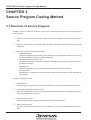
Chapter 3. Source Program Coding Method
Describes the structure of assembly language source programs that are processed by RASM77.
•
Chapter 4. Instruction Coding Method
Explains how to code 7700 Family instructions that can be used by RASM77.
•
Chapter 5. Pseudo Instruction Coding Method
Describes functions of and explains how to code the pseudo instructions provided by RASM77.
•
Chapter 6. Macro Instruction
Describes the macro instructions available with RASM77.
•
Chapter 7. Operation
Explains how to input RASM77 commands.
•
Appendix A. Error Messages
Lists error messages output by RASM77 along with explanation of the errors and actions to
be taken.
•
Appendix B. Pseudo Instructions
Lists and explains all pseudo instructions provided by RASM77.
•
Appendix C. Macro Instructions
Lists and explains all pseudo instructions provided by RASM77.
•
Appendix D. Instruction Set
Lists all 7700 Family instructions provided by RASM77.
1-1
CHAPTER 1. RASM77 USER’S MANUAL ORGANIZATION
•
Appendix E. Instruction Sets by Addressing Modes
Lists the 7700 Family instructions provided by RASM77 in each addressing mode.
1-2
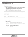
2.1 Functions
CHAPTER 2
Overview
RASM77 converts a source program written in assembly language (hereafter referred to as a
source file) into a relocatable file that can be processed by LlNK771 and LlB77 2. This step is
referred to as assembly. Relocatable files are converted into machine language data by LlNK77.
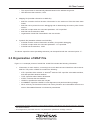
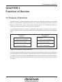
2.1 Functions
Development of a large software requires functions that enable several engineers to share programming resources such as data and existing codes. RASM77 offers the following functions to
facilitate this task.
1.
The user can specify any section name desired by the pseudo instruction, .SECTlON.
2.
Because there is no limit to the number of sections that can be specified, address specification is possible for linkage editing even on a user system that has ROM and RAM memories
that are divided into large number of separate areas.
3.
Versions of the relocatable files being linked can be verified by specifying the version number
with the pseudo instruction .VER.
4. The relocatable files to be linked can be specified by the pseudo instructions .LIB and .OBJ.
(This feature eliminates the need for specifying filenames during linkage editing.)
RASM77 also has the following assembly functions:
1.
The most efficient addressing mode is automatically selected based on the values in the
direct page register (DPR) and data bank register (DT).
2.
A TAG 3 file that stores error information can be created. (This feature enables efficient
assembly error correction.)
3.
Because RAM and ROM areas can coexist in a file, RASM77 can also be used as an
absolute assembler. (Linkage is required.)
1
2
3
LINK77 is the program name of the Series 7700 Family linkage editor.
LIB77 is the program name of the Series 7700 Family librarian.
This file is called a TAG file because it contains “tags” that show the locations of errors and warnings.
1-3
CHAPTER 2. OVERVIEW
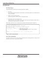
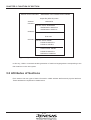
2.2 Files Created by RASM77
RASM77 creates three types of files as described below.
1.
Relocatable file
• A relocatable file contains machine language data and its relocation information.
• A relocatable file contains symbol information for use in symbolic debugging.
• A relocatable file can be linked by LlNK77 to create Intel HEX format machine language
data.
• Relocatable file is not created if an assembler error has occurred.
• File extension of relocatable file is .R77.
• Relocatable files should not be output to a printer or screen because they are in binary
format.
2.
Print file (hereafter referred to as PRN file)
• A PRN file contains source file data, addresses of source file data locations and various
data created by RASM77.
• A PRN file can be printed and used for debugging.
• A PRN file is generated when the command parameter “-L” is specified.
• The file extension of PRN files is .PRN.
• The structure of PRN files is described in detail in Section 2.3.
3.
TAG file
• A TAG file contains the assembly error messages and warning messages that were
generated during assembly.
• The file extension of TAG files is .TAG.
• TAG file should be referred to when making error corrections using an editor.
• A TAG file is generated when the command parameter “-E” is specified.
• The structure of TAG files is described in detail in Section 2.4.
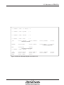
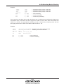
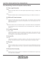
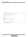
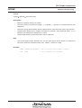
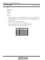
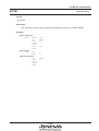
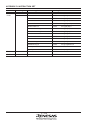
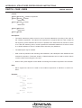
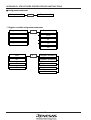
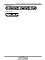
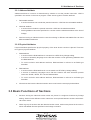
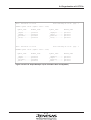
2.3 Structure of PRN File
Figures 2.1 through 2.5 show sample PRN files. A PRN file contains the following information:
1.
Source file data, addresses of source file data locations and data created by RASM77
(Figures 2.1 to 2.3 show this portion of PRN file.)
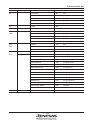
• A line that references an external label 4 is marked by ‘E’ next to the source file data.
• A line that references a public label 5 is marked by ‘P’ next to the source file data.
• A line that references a local label 6 is marked by ‘L’ next to the source file data.
1-4
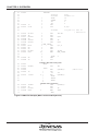
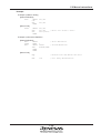
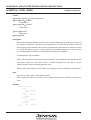
2.3 Structure of PRN File
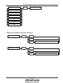
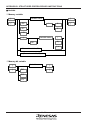
• A line that is an expansion of a macro is marked by ‘+’ next to the source file data.
• A line that references a symbol defined with .DEFINE is marked by ‘-’ next to the source
file data.
• The .INCLUDE nesting level is marked by the number corresponding to the level next to
the source file data (Figure 2.6 shows this portion of PRN file).
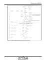
• Structured description source lines are output to a print file as comment lines. (Figure 2.7
shows this portion of PRN file).
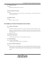
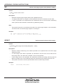
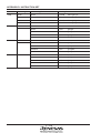
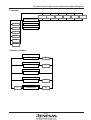
2.
Assembly information (Figure 2.4 shows this portion of PRN file)
This portion of a PRN file shows the number of errors, number of warnings, total number of
lines, number of comment lines and the memory size of each section.
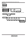
3.
Symbols listing (Upper section of Figure 2.5 shows this portion of PRN file)
The number of symbols per line in the symbol list depends on the “.COL” pseudo instruction.
If the number of columns specified with “.COL” is 99 or less, the number of symbols output is
4, if it is between 100 and 119 columns, the number of symbols output is 5, if it is 120 or
more, the number of symbols output is 6.
This portion of a PRN file lists the symbols and their values as they are defined in the
program in three groups:
• -D OPTION
Each symbol in this group is defined by specifying the command parameter “- D” in the
command line and referenced within the program.
• EQUATE
Each symbol in this group is defined by the pseudo instruction .EQU and referenced
within the program.
• UNUSED
Each symbol in this group is defined by either the command parameter “-D” or .EQU but
not referenced in the program.
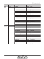
4.
Labels list (Lower section of Figure 2.5 shows this portion of PRN file)
This portion of a PRN file lists the labels and their values as they are defined in the program
in two groups:
• USED
Each label in this group is defined and referenced in the program.
• UNUSED
Each label in this group is defined but not referenced in the program.
5. When the number of columns specified by the pseudo instruction .COL is 132, the assembly
execution date and time is placed in the header of the PRN file list in the following format:
Sun Mar 31 15:06:42 1991
4
5
6
Refers to a label that is defined in another file. External labels and public labels are referred to as global
labels.
Refers to a label that is defined in this file and can be referenced by other files.
Refers to a label that is defined in this file and can be referenced only within the file.
1-5
CHAPTER 2. OVERVIEW
1
2
3
4
5
6
7
8
9
10
11
12
13
14
15
16
17
18
19
20
21
22
23
24
25
26
27
28
29
30
31
32
33
34
35
36
37
38
39
40
41
42
;
;
;
;
;
;
;
000000
(000000)
(000008)
8H BYTE
1AH BYTE
Start_up Routine
Data section
Initialized static variable area
.SECTION
.PUB
DATATOP:
NULLDT: .BLKB
TITLE: .BLKB
;
;
;
;
1H BYTE
1H BYTE
2H BYTE
BSSTOP:
WORK1: .BLKB
WORK2: .BLKB
WORK3: .BLKW
;
;
;
;
000000
(000000) 1000H BYTE
BSS
BSSTOP
1
1
1
HEAP section
Area used by memory handling functions such as malloc
.SECTION
.PUB
HEAPTOP:
HEAP_A: .BLKB
;
;
;
;
(000000) 1000H BYTE
001000
8
26
BSS section
Unitialized static variable area
.SECTION
.PUB
000000
(000000)
(000001)
(000002)
DATA
DATATOP
HEAP
HEAPTOP
1000H
STACK section
stack area
.SECTION
.PUB
.BLKB
STACK
STKTOP
1000H
STKTOP:
Figure 2.1 PRN File Example (Beginning of Source File)
1-6
2.3 Structure of PRN File
43
44
45
46
47
48
49
50
51
52
53
54
55
.PAGE
;
;
;
;
56
57
58
59
000000
000000
000002
C2FF
A90010
60
61
62
63
000005
000006
000009
00000C
1B
A90000
A20000
A00000
PROGRAM section
Program area
.SECTION
PROGRAM
.EXT
MAIN
.DPEXT
DPPAGE1:WK1,WK2
.DTEXT
DTPAGE1:TBL1,TBL2
.PUB
_INIT
.DATA
16
.INDEX
16
E
.DP
OFFSET DPPAGE1
↑ Indicates external label reference
E
.DT
BANK DTPAGE1
_INIT:
CLP
#0FFH
P
LDA
A,#STKTOP
↑ Indicates public label reference
TAS
LDA
A,#SIZEOF DATA
P
LDX
#OFFSET CONSTOP
P
LDY
#OFFSET DATATOP
Figure 2.2 PRN File Example (Middle of Source File)
1-7
CHAPTER 2. OVERVIEW
64
65
66
67
68
69
70
71
72
73
74
75
76
77
78
79
80
81
82
83
84
00000F 540000
P
MVN
000012 AD0000
E
LDA
000015 *42AD0000
E
LDA
↑ Indicates optimization
000019 A20000
E
LDX
00001C 202200
L
JSR
↑ References a local label
00001F 4C0000
E
JMP
;
000022
_SUB:
000022 9500
STA A,0,X
000024 42950A
STA B,10,X
000027 60
RTS
;
;
;
;
000000
000000
000006
000008
00000E
000014
00001A
000020
CONST
CONSTOP
.BYTE
0,0,0,0,0,0,0,0
.BYTE
'M37700 C Compiler Ver 1.0',0
;
.END
(0000H)
(0000H)
(0056H) LINES
(0021H) LINES
(000022H) BYTES
(000004H)
(001000H)
(001000H)
(000028H)
(000022H)
MAIN
.SECTION
.PUB
Figure 2.3 PRN File Example (End of Source File)
ERROR
COUNT
00000
WARNING COUNT
00000
TOTAL
LINE
00086
COMMENT LINE
00033
DATA
00000034
↑ Indicates the section name
BSS
00000004
HEAP
00004096
STACK
00004096
PROGRAM
00000040
CONST
00000034
#WK1
_SUB
CONST section
Initialized data area
000000000000
0000
4D3337373030
204320436F6D
70696C657220
56657220312E
3000
85
86
BANK CONSTOP, BANK DATATOP
A,DT:TBL1
B,TBL2
BYTES
BYTES
BYTES
BYTES
BYTES
Figure 2.4 PRN File Example (Assembly Information)
1-8
2.3 Structure of PRN File
*** SYMBOLS ( TYPE = -d OPTION ) ***
*** SYMBOLS ( TYPE = EQUATE
) ***
*** SYMBOLS ( TYPE = UNUSED
) ***
*** LABELS
( TYPE = USED
) ***
_SUB
000022' CONSTOP
000000p DATATOP
↑ Indicates a local label
000000p DPPAGE1
DTPAGE1
000000e MAIN
001000p TBL1
000000e
↑ Indicates a public label
TBL2
*** LABELS
000000e WK1
000000e
↑ Indicates an external label
( TYPE = UNUSED
) ***
_INIT
NULLDT
WORK2
000000p BSSTOP
000000' TITLE
000001' WORK3
000000e STKTOP
000000p HEAP_A
000008' WK2
000002'
Figure 2.5 PRN File Example (Symbol and Label List)
1-9
000000' HEAPTOP
000000e WORK1
000000e
000000p
000000'
CHAPTER 2. OVERVIEW
31
32
33
34
35
36
37
38
39
40
41
000014
42
43
44
45
46
47
48
49
50
51
52
53
54
55
56
57
000003 A27F02
000006 9A
000007 A90000
00000A 5B
00000B 89C200
00000E A90000
000011
000011 *9500
000013 CA
000014 CA
000015 E07E00
000018 D0F7
58
59
60
61
62
63
64
65
67
68
00001C
00001C
00001F
00001F
00001F
000020
790000
69
70
71
72
73
000023
000026
000027
00002A
990A00
88
C00000
D0F3
000000
000001
00001A
00001B
INITIAL:
78
C238
F8
58
A00A00
18
1
1
1
1
1
1
1
.section
.include
.DATA
.INDEX
.DP
.DT
SEI
CLP
prog
initial.a77
16
16
0
0
.include
clr_ram.a77; Call in
; initial.a77
m,x,D
2
LDX
#027FH
2
TXS
2
LDA
A,#0
2
TAD
2
LDT
#0
2
LDA
A,#0
2 RAM_CLEAR:
2
STA
A,0,X
2
DEX
2
DEX
2
CPX
#07EH
L2
BNE
RAM_CLEAR
2
1
.DATA
8
1
SEM
1
CLI
↑
Indicates .INCLUDE nesting level
MAIN:
LDY
#10
LOOP:
ADD
A,WORK,Y
+
CLC
+
.IF
"Y"
L +
ADC
A,WORK,Y
+
.ELSE
+
.ENDIF
+
.ENDM
↑
Indicates macro expansion
L
STA
A,DATA,Y
DEY
CPY
#0
L
BNE
LOOP
.END
Figure 2.6 PRN File Example (Macro and Include Expansion)
1 - 10
; Macro call
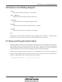
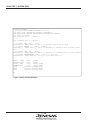
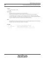
2.3 Structure of PRN File
1
; *** 7700 Family PREPROCESSOR V5.00.00 ***
2
.language
PRE77_Rev01
3
.source
sample.p77
4
.SECTION
RAM
5
.func
_sample_0
6
.ORG
0000H
7 (000000)
1H BYTE
WORK1: .BLKB
1
8 (000001)
1H BYTE
WORK2: .BLKB
1
9
.endfunc
_sample_0
10
.SECTION
INIT
11
.func
_sample_1
12
;FLAG_0 .EQU
0,WORK1← Structured code source line
13
FLAG_0
.define
WORK1← Structured code expansion
14
;FLAG_1 .EQU
1,WORK1
15
FLAG_1
.define
WORK1
16
.endfunc
_sample_1
17
.section
structprog
18
.func
_sample_2
19
;
for [ DP:FLAG_0 ] == 0
20
.cline
9 ← Source level debugging information
21 000000
..F1: ← Structured code label
22 000000 2400010011
-L
BBS
#00001H,DP:WORK1,..F2
↑ Indicates reference to string definition symbol
23
;
if [ DP:FLAG_1 ] == 1
24
.cline
10
25 000005 340002000A
-L
BBC
#00002H,DP:WORK1,..I3
26
;
[ WORK1 ] = 0
27
.cline
11
28 00000A A90000
LDA
A,#0
29 00000D *8500
L
STA
A,WORK1
30
;
[ WORK2 ] = 0
31
.cline
12
32 00000F A90000
LDA
A,#0
33 000012 *8501
L
STA
A,WORK2
34
;
endif
35
.cline
13
36 000014
..I3:
37 000014 80EA
L
BRA
..F1
38
;
next
39
.cline
14
40 000016
..F2:
41
.endfunc
_sample_2
42
.end
Figure 2.7 PRN File Example (Structured Preprocessor Section)
1 - 11
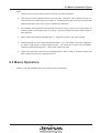
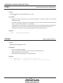
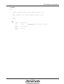
CHAPTER 2. OVERVIEW
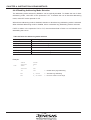
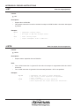
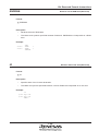
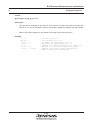
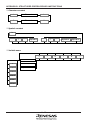
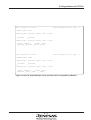
2.4 Structure of TAG File
Figure 2.6 shows a sample of a TAG file. A TAG file contains the following information:
1.
Source information
For each occurrence of error or warning, list line number, location, object code and source
file contents are specified.
2.
TAG information
For each occurrence of error or warning identified by source information, filename, line
number within the file, sequential line number, error number and error message are specified.
The TAG file should be printed and referenced when correcting errors with an editor.
115 00F025
TEST.ASM 115
127 00F031
TEST.ASM 127
551 00F42B
TEST.ASM 551
593 00F4FC
TEST.ASM 593
EAEA
( TOTAL LINE 115
EAEAEA
( TOTAL LINE 127
EAEA
( TOTAL LINE 551
EAEAEAEAEAEA
( TOTAL LINE 593
BCC
) Error 18:
LDA
) Error 20:
BRA
) Error 20:
LDA
) Error 23:
LOOP2
Relative jump is out of range
A,#data
Reference to undefined label or symbol 'data'
TEST2
Reference to undefined label or symbol 'TEST2'
A,(work,x ; data set
'()' format error ';'
Figure 2.8 TAG File Example
1 - 12
3.1 Structure of Source Program
CHAPTER 3
Source Program Coding Method
3.1 Structure of Source Program
A source program written in assembly language is made up of lines. Each source program line
must comply with the following rules:
1. Each line must be complete by itself, and an instruction cannot be coded on more than one
line.
2.
Each line may contain no more than 256 characters. The assembler program ignores coding
beyond 256 characters.
3.
Each line consists of the following fields:
• Symbol/label field
Label for referencing this line from other locations or symbol whose value is to be set by
the .EQU pseudo instruction is coded in this field.
•
Op-code/pseudo instruction field
7700 Family instruction mnemonic (hereafter referred to as op-code) or pseudo instruction
is coded in this field.
•
Operand field
Object of processing by op-code or pseudo instruction is coded in this field.
•
Comment field
Specification in this field is not processed by the assembler, and the user can use this
field for any purpose.
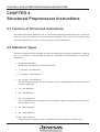
There are five types of lines.
1.
Instruction line
An instruction line specifies a 7700 Family instruction. The assembler converts the specifications on this line to machine language data.
2.
Structured preprocessor instruction line
A structured preprocessor instruction line specifies the structured preprocessor language that
is processed by PRE77.
3.
Pseudo instruction line
A pseudo instruction line specifies the information necessary for assembly.
1 - 13
CHAPTER 3. SOURCE PROGRAM CODING METHOD
4.
Macro instruction line
A macro instruction line specifies the macro definition. This line is processed by the assembler.
5.
Comment line
A comment line is not processed by the assembler. Therefore, it can be used by the user for
any purpose.
3.2 Line Formats
This section describes the format of each type of line. The following conventions are used for these
descriptions:
1.
▲ and ▲ specify space or tab code. ▲ is required, and ▲ is optional.
2.
Colon (:) may be omitted when specifying a label, but if omitted, a space or a tab code must
be specified between label and pseudo instruction.
3.2.1 Instruction Line
Shown below is the format of an instruction line:
▲ Label: ▲ Op-code ▲ Operand ▲ ; Comment <RET>
▲† Op-code ▲ Operand ▲ ; Comment <RET>
† Because RASM77 identifies each instruction by its reserved word, a line can begin with an opcode if there is no label.
3.2.2 Structured Preprocessor Instruction Line
This line is not processed by the assembler. Refer to Part 2. Chapter 3 for details concerning this
line.
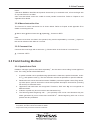
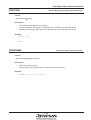
3.2.3 Pseudo Instruction Line
Shown below is the format of pseudo instruction line:
▲Label: ▲ Pseudo-op ▲ Operand ▲ ; Comment <RET>
▲ Symbol ▲ .EQU ▲ Operand ▲; Comment <RET>
▲‡ Pseudo-op ▲ Operand ▲ ; Comment <RET>
1 - 14
3.2 Line Formats
Notes:
‡ Because RASM77 identifies each pseudo instruction by its reserved word, a line can begin with
an op-code if there is no label.
Also note that labels cannot be coded for some pseudo instructions. Refer to Chapter 5 and
Appendix B for details.
3.2.4 Macro Instruction Line
The format of a macro instruction line is shown below. Refer to Chapter 6 and Appendix E for
details concerning this line.
▲ Macro name:▲ Macro Instruction ▲ Operand ▲ ; Comment <RET>
Note:
If there are more than one data in the operand, they must be separated by a comma (,). Space or
tab can be coded on both sides of a comma.
3.2.5 Comment Line
Comment line must begin with a semicolon (;). Shown below is the format of a comment line:
▲ ; Comment <RET>
3.3 Field Coding Method
3.3.1 Symbol/Label Field
RASM77 manages symbols and labels separately 1, but the same name coding format applies to
both. The coding format is described below.
1.
A symbol or label can be specified using alphanumeric characters, special characters, underline (_) and question mark (?). The first character must be an alphabetic or special character.
2. Reserved words cannot be used as names. RASM77 processes register names, flag names,
op-code names, pseudo instruction names and operand description instructions (including
DP and DT) as reserved words.
3. Uppercase and lowercase are recognized. Therefore, “BIG” and “Big” are recognized as
different names.
4. A label or symbol may be no more than 255 characters long.
5. The following labels beginning with ‘..’ (two periods) must not be used because they are
labels generated by macro instructions and PRE77 2. Labels beginning with one or three
periods are also prohibited.
1
2
Names defined by the .EQU pseudo instruction or an instruction with the command parameter -D are treated
as symbols, and other names are treated as labels.
Preprocessor that processes structured code lines.
1 - 15
CHAPTER 3. SOURCE PROGRAM CODING METHOD
When specifying a label, it must be followed immediately by a colon (:). However, for compatibility
with previous version, the colon may be omitted if the command option “-U” is specified. If the colon
is omitted, a space or a tab code is required between the a label and pseudo instruction. It is
recommended that this colon be always specified to make it easier to differentiate labels from
symbols and to make label search by the editor more efficient.
3.3.2 Op-code/Pseudo Instruction Field
A 7700 Family instruction mnemonic or a pseudo instruction is specified in the op-code/pseudo
instruction field. The specification format is described below.
1. No distinction is made between uppercase and lowercase characters for op-codes and pseudo
instructions. Thus, both “NOP” and “nop” mean the same.
This field is described in more detail in Chapters 4 and 5.
3.3.3 Operand Field
Information regarding the target of op-code or pseudo instruction is specified in the operand field.
The specification format is described below.
1. If there are two or more operand data, they must be separated by a comma (,).
2. Space or tab code may be specified on either side of a comma.
This field is described in more detail in Section 3.4.
3.3.4 Comment Field
Any user information may be specified in the comment field. The specification format is described
below.
1. A comment field must begin with a semicolon (;).
2. Any character may be used in the comment field.
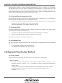
3.4 Operand Field Coding Method
3.4.1 Data Format
Operand field may be specified with data in any of the following four data formats:
1. Numeric constant
•
A numeric constant can be specified as a positive or negative value by using the ‘+’ or ‘-’
instruction as prefix. If neither ‘+’ nor ‘-’ is specified, the numeric constant is processed as a
positive value.
•
A binary, octal, decimal or hexadecimal number may be specified as a numeric constant.
•
When specifying a binary numeric constant, the value must be followed by ‘B’ or ‘b’.
Example: .BYTE 100110B
1 - 16
3.4 Operand Field Coding Method
•
•
•
When specifying an octal numeric constant, the value must be followed by ‘O’ or ‘o’.
Example: .BYTE 70o
When specifying a decimal numeric constant, only an integer value can be specified.
Example: .BYTE 100
When specifying a hexadecimal numeric constant, the value must be followed by ‘H’ or ‘h’. If
the hexadecimal value begins with an alphabetic character (A to F), it must be prefixed with
0.
Example 1: .BYTE 64H
Example 2: .BYTE 0ABH
2. Character string constant
•
Any ASCll code character may be used in a character string constant.
•
Character string constant must be enclosed between single quotes (‘ ’)or double quotes (“ ”).
Example: .BYTE 'A' => Sets 41H.
•
If '\' is used in a string literal, the character immediately following the '\' is processed as
character string data. When using '\' in a character string, write it as '\\.'
3. Label or symbol
•
A label has a 24 bit data value, and a symbol has a 32 bit data value.
4. Expression
•
Numeric expression can be specified as a combination of instructions, numeric constants,
character string constants, labels or symbols.
•
An expression is calculated from left to right. (No operators priorities are recognized.)
Example 1: 2*3 => Result is 6.
Example 2: 2+6/2 => Result is 4.
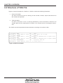
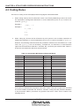
3.4.2 Operators
Table 3.1 lists the operators that may be used with RASM77.
1 - 17
CHAPTER 3. SOURCE PROGRAM CODING METHOD
Table 3.1 List of Operators
Operator1
Description
+
Addition
Subtraction
Multiplication
*
/
Divide
%
Remainder of division
<<
Left shift
>>
Right shift
&
Logical AND on bits
|
Logical OR on bits
^
Logical exclusive-OR on bits
+
Unary operator specifying a positive number
Unary operator specifying a negative number
~
Unary operator specifying bit inversion
@2
Operator that converts the immediately following symbol to character string
3,4
SIZEOF
Unary operator to obtain section size
4
BANK
Unary operator to extract high-order 8 bits of label or symbol
OFFSET4
Unary operator to extract low-order 16 bits of label or symbol
Notes:
1. Operation is executed from left to right. (No operator priorities are recognized.)
Example 1: 2+6/2 => Result is 4.
Example 2: 2*3 => Result is 6.
2.
The symbols concatenated by the @ operator must be absolute values. If a forward-referenced symbol is specified, an error occurs.
3.
SlZEOF value is determined at link time regardless of whether the referenced section is
relocatable or absolute. Accordingly, the same limitations as for external labels apply to the
location where the SlZEOF instruction may be specified. (It cannot be specified in the operand of pseudo instructions such as .ORG and .BLKB.)
4.
A space must be specified between SIZEOF, BANK, or OFFSET instruction and label, symbol or section name.
Example:
.DT BANK DATA1
1 - 18
4.1 Addressing Mode
CHAPTER 4
Instruction Coding Method
4.1 Addressing Mode
The basic mode in which instructions specify the data to be processed is called an addressing
mode. 7700 Family supports 28 addressing modes, and the operand coding format is prescribed for
each of these addressing modes.
The following summarizes the characteristics of the addressing modes as they relate to operand
coding:
1.
Accumulator addressing mode
This addressing mode is for processing the data in an accumulator. The Series 7700 Family
CPU has A and B accumulators, and the name of the accumulator to be used must be
specified at the beginning of the operand field. Note that, if accumulator B is specified, the
bytes count of machine language data will increase by 1 byte.
Example:
2.
LDA A,#IMMDATA
Immediate addressing mode
This addressing mode is for directly specifying the data to be processed in the operand field.
The value in the operand must be prefixed by “#“.
Example:
LDM #IMMDATA,MEMORY
3.
Direct addressing mode
This addressing mode is for using the 16 bit value in the direct page register (DPR) as the
base address and specifying an 8 bit offset value to the base address in the machine
language data. Bank address is fixed at 0. The method of coding direct addressing in
assembler instructions is described in detail in Section 4.3.
4.
Absolute addressing mode
This addressing mode is for using the 8 bit value in the data bank register (DT) as the base
address and specifying the lower-level 16 bit address in the machine language data. The
method of coding absolute addressing in assembler instructions is described in detail in
Section 4.3.
5.
Absolute long addressing mode
In this addressing mode, a 24 bit address value is specified in the operand field. (The entire
memory space of 7700 Family can be used.) This addressing mode is used when the label
specified in the operand field cannot be processed in the direct or absolute addressing mode.
The method of coding absolute long addressing in assembler instructions is described in
detail in Section 4.3.
1 - 19
CHAPTER 4. INSTRUCTION CODING METHOD
6.
Indexed addressing mode
In this addressing mode, address of the data to be processed is modified by the content of
register X or Y. Register name must be specified after a comma (,).
Example:
7.
ADC A,DATA1,X
Direct indirect addressing mode
In this addressing mode, the data to be processed is specified indirectly by memory address.
The memory location where the 2 byte address of the data to be processed is stored is
specified in the operand field. The high-order 8 bits contain the data bank register value. The
memory address is specified in the operand field by the same method as for direct addressing. The operand value must be enclosed in parentheses.
Example:
LDA A,(INDATA)
When storing a 3 byte address in the memory location, “L”, must be added at the end of the
op-code.
Example:
8.
LDAL A,(INDATA)
Absolute indirect addressing mode
In this addressing mode, the data to be processed is specified indirectly by memory location.
The memory location where the 2 byte address of the data to be processed is stored is
specified in the operand field. The low-order 16 bits of memory address is specified in the
operand field, and the program bank register value is specified in the high-order 8 bits. The
operand value must be enclosed in parentheses.
Example:
JUMP (PROCESS1)
When storing a 3 byte address in the memory location, “L” must be added at the end of the
op-code.
Example:
9.
JMPL (PROCESS2)
Relative addressing mode
In this addressing mode, the branch destination is specified by a relative byte count from the
current program counter value. The relative value itself cannot be specified in the source
program. If a label or object location is specified in the operand field, the assembler calculates the relative value.
Example:
BBA LABEL
Refer to Appendix C for the coding format of each addressing mode.
1 - 20
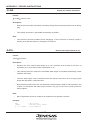
4.2 Data Length Specification
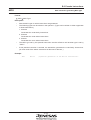
4.2 Data Length Specification
7700 Family CPU can control data length and index register length with the CPU internal flag.
Table 4.1 summarizes the association between the flags and the assembler.
Table 4.1 Association of CPU Internal Flags and Assembler
• Data length selection flag (m)
Flag status
Meaning
Reset state
m=0
16 bit operation
Reset state after CPU reset.
This is the default value when RASM77 is started.
m=1
8 bit operation
• Index register length selection flag (x)
Flag status
Meaning
x=0
16 bits long
x=1
Reset state
Reset state after CPU reset.
This is the default value when RASM77 is started.
8 bits long
Because the machine language code for each instruction is identical regardless of the flags, flags
do not affect assembler execution except in the case of immediate addressing. In the case of
immediate addressing, the bytes count of the immediate value data that must be specified in the
operand field depends on the data length. Therefore, the assembler must generate a code that is
appropriate for the flag. RASM77 allows specification of status by one of two methods:
1.
Direct specification in instruction’s op-code
Example 1:
LDA.B A,#50H ; Specifies an 8 bit immediate value (50H).
Example 2:
LDA.W A,#50H ; Specifies a 16 bit immediate value (0050H).
2.
Declaration of default value by pseudo instruction INDEX or .DATA
Example 1:
.INDEX 16
; Declares that the index length is 16 bits.
Example 2:
LDX #200H
; Specifies processing at the default index length (16 bits).
RASM77 allows for assemble control by default values of data and index lengths.
If a command parameter "-F" is specified, symbols "M_FLAG" and "X_FLAG" are handled as
reserved words. If this command parameter is not specified, "M_FLAG" and "X_FLAG" can be
used as any symbols or labels.
These reserved words can be used to verify the content of the flag 'm' or 'x' that is currently
recognized by the assembler by using them along with a pseudo-instruction ".IF" that performs
conditional assembling.
The functions of "M_FLAG" and "X_FLAG" described in Table 4.2.
1 - 21
CHAPTER 4. INSTRUCTION CODING METHOD
Table 4.2 Function of M_FLAG and X_FLAG
Function
The value changes with the setup value of ".DATA."
The value of "M_FLAG" = 1 when the data length is set to 16 bits.
The value of "M_FLAG" = 0 when the data length is set to 8 bits.
The value changes with the setup value of ".INDEX."
The value of "X_FLAG" = 1 when the index length is set to 16 bits.
The value of "X_FLAG" = 0 when the index length is set to 8 bits.
Symbol
M_FLAG
X_FLAG
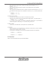
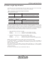
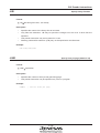
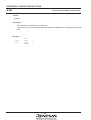
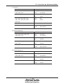
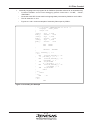
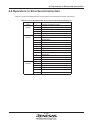
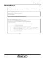
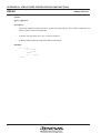
Figure 4.1 shows an example of a conditional assemble program using "M_FLAG" and "X_FLAG."
BIT8:
.MACRO
.DATA
.INDEX
.IF
sep
.ELSE
clp
.ENDIF
8
8
M_FLAG
m,x
m,x
Figure 4.1 Example of conditional assemble based on data and index lengths
Notes:
1. Pseudo instructions do not generate instructions that manipulate the CPU internal flags.
Therefore, the user program must control the assembler’s default value to be consistent with
the processor status.
2.
Immediate value must be used when specifying the data length directly in the operand of an
instruction.
1 - 22
4.3 Setting Direct Page and Absolute Addressing
4.3 Setting Direct Page and Absolute Addressing
the 7700 Family CPU has two internal registers named direct page register (DPR) and data bank
register (DT) to enable memory accessing with the least number of codes for each type of address
space. By using these registers, 7700 Family’s memory space (16M bytes) can be accessed more
efficiently. The functions of DPR and DT are described below.
1.
Direct page register (DPR)
DPR is a 16 bit register. At the machine language data level, direct addressing specifies the
target address with an 8-bit offset to DPR. (Bank is always 0.)
If only a label is specified in the source program’s operand field, the assembler checks
whether the label is within offset values 00 to 0FFH from the current DPR value. When direct
addressing is possible, the assembler calculates the offset value and generates machine
language data.
2.
Data bank register (DT)
DT is an 8 bit register. At the machine language data level, absolute addressing specifies a
low-order 16 bit address with the value in DT as the bank address. If only a label is specified
in the source program’s operand field, the assembler checks if the current DT value and the
label’s high-order 8 bit value are identical. When absolute addressing is possible, the assembler calculates the low-order 16 bit value and generates machine language data. Table 4.3
summarizes the relations of DPR and DT to assembler.
Table 4.3 Relationship between DPR, DT and Assembler
Register
Reset state
DPR
0000H is set in DPR after CPU reset.
This is the default value when RASM77 is started.
DT
00H is set in DT after CPU reset.
This is the default value when RASM77 is started.
4.4 Addressing Mode Selection
RASM77 provides the following three addressing modes when a symbol, label, or absolute value is
coded in the operand of an instruction:
1. Direct addressing mode
2. Absolute addressing mode
3. Absolute long addressing mode
1 - 23
CHAPTER 4. INSTRUCTION CODING METHOD
RASM77 allows the addressing mode to be selected from these three modes. The method of
selection depends on the symbol, absolute value, or label that is the target of the operation. For
label operation, the value in the direct page register (DPR) and data bank register (DT) directly
affects the selection of the addressing mode.
Described below are descriptions on how to set the DPR and DT registers followed by the description of addressing modes during symbol and absolute value, and label operations.
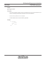
4.4.1 Setting the Direct Page Register and Data Bank Register
In order to change the direct page and bank to be used in RASM77, the value of the direct page
register and data bank register must be declared with the .DP and .DT pseudo instructions beforehand as shown below.
Example:
100
← Set 100 in direct page register (100H to 1FFH)
1
← Set 1 in data bank register (bank 1)
A, #100H
.DP
.DT
LDA
TAD
LDT
#1
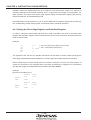
The operand of the .DP and .DT pseudo instructions can be either a numeric value specifying the
direct page start address and bank address or a direct page name label and bank name label.
When referencing the labels DLAB and work coded in sample1.a77 from the PRO section of
samp2.a77 as shown in the example below, the value of DPR and DT registers can be declared
with the direct page name label DPR100 and bank name label BANK2.
Example:
[Source file for samp1.a77]
DPR100:
DLAB:
.SECTION
.ORG
DATA1
100H
.BLKW
2
.SECTION
.ORG
BANK2:
work:
.BLKB
DATA2
20000H
2
1 - 24
4.4 Addressing Mode Selection
[Source file for samp2.a77]
.SECTION
.DPEXT
.DTEXT
PRO
DPR100:DLAB
BANK2:work
.DP
.DT
LDA
TAD
LDT
OFFSET DPR100 ← Set 100 in direct page register (100H to 1FFH)
BANK
BANK2 ← Set 1 in data bank register (bank 1)
A, #OFFSET DPR100
#BANK BANK2
The scope of the direct page and bank coded in the operand of .DP and .DT is determined during
link.
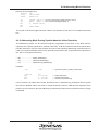
4.4.2 Addressing Mode During Symbol•Absolute Value Operation
The addressing mode can be selected explicitly regardless of the value in the DPR and DT
registers when public specification pseudo instruction .PUB and external reference specification
pseudo instruction .EXT are used for data and one of the following addressing mode specifiers is
used in the symbol•absolute value in the operand (except when OFF is specified as the operand of
the .DP or .DT pseudo instruction.)
• DP: ........................ Direct addressing
• DT: ........................ Absolute addressing
• LG: ........................ Absolute long addressing
Example:
.EXT
SYM1
← Specified as public (.PUB) in another file
.SECTION
AND
AND
AND
PRO
A, DP:SYM1
A, DT:SYM1
A, LG:SYM1
← Direct addressing
← Absolute addressing
← Absolute long addressing
If an instruction can select direct mode, absolute mode, or absolute long mode and uses a symbol
that has an absolute value, the value is compared with the value in DPR and DT registers at the
location of the instruction and the addressing mode that provides the most efficient memory usage
is selected.
1 - 25
CHAPTER 4. INSTRUCTION CODING METHOD
Example:
LAB1
.SECTION
.ORG
.BLKW
DATA
100H
1
.SECTION
.DT
.DP
LDA
TDA
LDT
PRO
0
100H
A, #100H
AND
A, LAB1
#0
← Direct addressing
4.4.3 Addressing Mode During Label Operation
The addressing mode can be selected explicitly regardless of the value in the DPR and DT
registers when public specification pseudo instruction .PUB and external reference specification
pseudo instruction .EXT are used for data and one of the following addressing mode specifiers is
used in the label in the operand (except when OFF is specified as the operand of the .DP or .DT
pseudo instruction.)
• DP: ........................ Direct addressing
• DT: ........................ Absolute addressing
• LG: ........................ Absolute long addressing
Example:
.EXT
LAB1
← Specified as public (.PUB) in another file
.SECTION
AND
AND
AND
PRO
A, DP:LAB1
A, DT:LAB1
A, LG:LAB1
← Direct addressing
← Absolute addressing
← Absolute long addressing
In addition, the following external reference specification pseudo instructions can be used to specify
the addressing mode during data reference. In this case, the addressing mode specifier can be
omitted in the operand.
•
•
•
.DPEXT ................ Direct addressing
.DTEXT ................ Absolute addressing
.EXT ..................... Absolute long addressing
1 - 26
4.4 Addressing Mode Selection
Example:
.DPEXT
.DTEXT
.EXT
.SECTION
AND
AND
AND
LAB1
LAB2
LAB3
PRO
A, LAB1
A, LAB2
A, LAB3
← Specified as public (.PUB) in another file
← Specified as public (.PUB) in another file
← Specified as public (.PUB) in another file
← Direct addressing
← Absolute addressing
← Absolute long addressing
If an instruction can select direct mode, absolute mode, or absolute long mode and the data has a
relocatable value coded with the direct page name label or bank name label associated with
.DPEXT or .DTEXT, the appropriate addressing mode is selected by comparing them with the
direct page name label or bank name label coded with .DP or .DT.
Example:
.DPEXT
.DTEXT
.SECTION
.DP
.DT
directpage_name:DPLAB← directpage_name: Direct page name label
databank_name:DTLAB ← databank_name: Bank name label
PRO
OFFSET directpage_name
BANK
databank_name
AND
AND
A, DPLAB
A, DTLAB
← Direct addressing
← Absolute addressing
1 - 27
CHAPTER 4. INSTRUCTION CODING METHOD
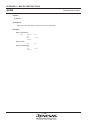
4.4.4 Disabling Addressing Mode Selection
The addressing mode selected by RASM77 can be explicitly disabled. To disable the use of direct
addressing mode, code OFF as the operand of .DT. To disable the use of absolute addressing
mode, code OFF as the operand of .DP.
When direct addressing mode is disabled, absolute or absolute long addressing mode is selected.
When absolute addressing mode is disabled, direct or absolute long addressing mode is selected.
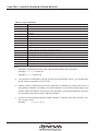
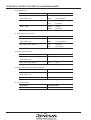
If OFF is written in the operand of .DP or .DT, the rules described in Table 4.4 are followed when
assembling the source.
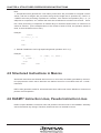
Table 4.4 Rules for addressing mode selection
Description format
DP:label
DP:symbol
DP:absolute value
DT:label
DT:symbol
DT:absolute value
Processing by RASM77
Error
Selects direct addressing mode
Selects direct addressing mode
Error
Selects absolute addressing mode
Selects absolute addressing mode
Example:
LAB:
.DPEXT
.SECTION
.BLKB
DPLAB
DATA
1
.SECTION
.DP
PRO
OFF
← Disable direct page addressing
LDA
STA
A, DPLAB
A, DP:ADDR1
← Absolute long addressing
← Error 22: Value is out of range
1 - 28
4.4 Addressing Mode Selection
Note:
1.
When using a relocatable local label in direct or absolute addressing, write "DP:" or "DT:" in
the operand. If only a local label is written, the assembler uses absolute long addressing.
2.
If a label specified with the pseudo instruction .DPEXT is coded in the operand and operation
is performed on that label, direct addressing is also used for the code generated as the result
of the operation.
Example:
.DPEXT
STA
WORKA
A,WORKA+1
; ← Specify external label of a direct page
; ← Treat operation result as direct page
In this case, the instruction STA is assembled using direct addressing. However, whether the
operation result is within the scope of direct addressing is determined during linkage. The
same is true for the label specified with .DTEXT.
3. If the command option “-Q” is specified, a warning is issued for instruction lines that specify
other addressing mode with codes such as “LG:” for labels specified with .DPEXT or .DTEXT.
1 - 29
CHAPTER 5. PSEUDO INSTRUCTION CODING METHOD
CHAPTER 5
Pseudo Instruction Coding Method
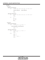
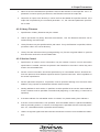
5.1 Function of Pseudo Instructions
A pseudo instruction declares or specifies 1 the assembler to generate the intended machine language data. RASM77 offers 52 pseudo instructions, and they can be grouped into the following five
functional groups:
1. Assembly control pseudo instructions
•
Does not generate data but controls generation of machine language data that corresponds
to the instruction.
•
Does not affect address updating.
•
There are 12 assembly control pseudo instructions:
.INDEX, .DATA
Declares data length
.DT, .DP
Declares DT or DPR value
.IF, (ELSE), .ENDIF Conditional assembly
.INCLUDE
Declares file to be included in program
.EQU
Equation
.END
Declares end of program
.ASSERT
Outputs a message
.ERROR
Declares assembly error
.DEFINE
Defines a string
1
The term “declare” is used when a pseudo instruction specifies a default to the assembler and the term
“specify” is used when a pseudo instruction specifies an instruction that affects the output file.
1 - 30
5.1 Function of Pseudo Instructions
2. Location control pseudo instructions
•
Updates address.
•
Data definition pseudo instruction generates constant data.
•
There are 10 pseudo instructions in this group:
.ORG
Declares location
.BLKB, .BLKW, .BLKA, . BLKD
Allocates RAM area
.BYTE, .WORD, .ADDR, .DWORD Defines data
.EVEN
Corrects location alignment
3. Linkage control pseudo instructions
•
Performs controls related to linkage processing.
•
There are 8 pseudo instructions in this group:
.SECTION
Specifies section name
.DPEXT, .DTEXT, .EXT, PUB
Specifies global label name
.OBJ, .LIB
Specifies linkage filename
.VER
Specifies version
4. Listing control pseudo instructions
•
Performs controls related to output of PRN file.
•
There are 7 pseudo instructions in this group:
.PAGE
Specifies new page and title
.COL ,.LINE
Specifies listing format (columns and row count)
. LIST, .NLIST
Outputs/suppresses list
.LISTM, .NLISTM
Outputs/suppresses macro expansion list
5. Source level debug support
•
Outputs information necessary for source line debug to object file.
•
There are 6 pseudo instructions in this group:
.CLINE
Outputs column information
.FUNC, .ENDFUNC
Specifies start/end of function
.LANGUAGE
Outputs the language used
.POINTER
Sets the pointer length
.SOURCE
Sets the source file name
6. Reserved pseudo instructions
•
A number of pseudo instructions are reserved for future use. These instructions do not affect
assembly.
•
There are 9 pseudo instructions in this group:
.PROGNAME
Declares program name
.IO, .ENDIO, .RAM, .ENDRAM
Declares RAM area name
.PROCMAIN, .PROCSUB, .PROCINT, .ENDPROC Declares module name
Functions of each pseudo instruction group are described in the next section.
1 - 31
CHAPTER 5. PSEUDO INSTRUCTION CODING METHOD
5.2 Assembly Control Pseudo Instructions
5.2.1 Data Length Declaration
.INDEX
Declares the default value for the index register length selection flag (x). For details, see
Section 4.2.
.DATA
Declares the default value for the data length selection flag (m). For details, see Section 4.2.
5.2.2 DPR and DT Value Declaration
.DP
Declares the default value for the direct page register. The assembler selects the optimal
addressing mode based on the DPR value specified for this and subsequent lines. For
details, see Section 4.3.
.DT
Declares the default value for the data bank register. The assembler selects the optimal addressing mode based on the DT value declared for this and subsequent lines. For details, see
Section 4.3.
5.2.3 Conditional Assembly
.IF, (ELSE), .ENDIF
Instructs the assembler to select the assembly location based on the symbol value. This
pseudo instruction can be used to manage programs for different specifications by a single
source program, to control assembly of test routines, etc.
5.2.4 Include File
.INCLUDE
Instructs the assembler to include the contents of a file where this pseudo instruction is
specified. This pseudo instruction is useful when editing a large source program in parts.
5.2.5 Equation
.EQU
Defines an absolute value for a symbol. The same symbol can be redefined within the same
program. If a forward reference is made to a symbol that is redefined, the last definition takes
effect.
5.2.6 Declare End of Assembly
.END
Declares the end of source program to be assembled. The assembler does not process any
source data after this declaration.
1 - 32
5.3 Address Control Pseudo Instructions
5.2.7 Message Output
.ASSERT
Displays the specifies string on the screen.
5.2.8 Assembly Error Output
.ERROR
Displays the specifies string on the screen and stops assembly. The assembler does not
process subsequent lines.
5.2.9 Define String
.DEFINE
Defines a string to a symbol.
5.3 Address Control Pseudo Instructions
5.3.1 Address Declaration
.ORG
Declares the address for the next line. The section in which this pseudo instruction is specified will have the absolute attribute, and address specification cannot be made for linkage
processing. This pseudo instruction can be used in areas where the address is fixed such as
an interrupt vector.
5.3.2 Memory Allocation
.BLKB, .BLKW, .BLKA, .BLKD
Allocates a RAM memory area of the size specified by operand.
5.3.3 Data Definition
.BYTE, .WORD, ADDR, DWORD
Generates data specified by operand in the ROM area.
5.3.4 Correct Address Alignment
.EVEN
Changes an odd numbered address to an even numbered address. Nothing occurs if the
current address is even numbered. This pseudo instruction can be used to set the beginning
of each data in a character string data in a byte-by-byte data area to an even numbered
address.
1 - 33
CHAPTER 5. PSEUDO INSTRUCTION CODING METHOD
5.4 Linkage Control Pseudo Instructions
5.4.1 Section Name Specification
.SECTION
Specifies the section name for the program that follows this line. RASM77 requires specification of a section name using this pseudo instruction at the beginning of every program.
5.4.2 Global Label Name Specification
.DPEXT, .DTEXT, .EXT
Specifies an externally referenced label or symbol name. The label names specified by these
pseudo instructions must be specified as public labels in other files.
.PUB
Specifies that a label or symbol defined in this file can be referenced by other files.
5.4.3 Linkage Filename Specification
.OBJ, .LIB
Specifies the name of relocatable file to be linked or the name of library file. The files
declared by these pseudo instructions are automatically referenced by the linker so that
linkage command specification is simplified.
5.4.4 Version Control
.VER
Specifies the version name of a relocatable file. Version name consistency between relocatable
files can be checked during linkage processing by specifying the version confirmation command parameter “-V”.
5.5 Listing Control Pseudo Instructions
.PAGE
Specifies new page and title of a listing.
.COL, LINE
Specifies the number of columns or rows for a listing. These pseudo instructions may be
specified only one time each in a source file.
.LIST, .NLIST
Specifies control of listing output to a PRN file. These pseudo instructions should be used
when only a portion of a listing is necessary as when partially debugging a program.
.LISTM, .NLISTM
Specifies whether to output macro expansion lines to PRN file.
1 - 34
5.6 Source Level Debug Support
5.6 Source Level Debug Support
.CLINE
Sets the line number necessary for source debug.
.FUNC, .ENDFUNC
Specifies the start and end of function (subroutine).
.LANGUAGE
Sets the information concerning the language used.
.POINTER
Sets the byte length of pointer variable used by C compiler.
.SOURCE
Sets the source file name required for source debug.
Note:
Listed above are the pseudo-instructions output by PRE77 and C compiler. If these pseudoinstructions are written in the source program, the assembler may output an error.
5.7 Reserved Pseudo Instructions
Reserved pseudo instructions are reserved for future expansion of the assembler. If these instructions are specified in a source file, they will not cause errors. They also will not affect the assembly
results. Reserved pseudo instructions may be used when checking a source file’s contents by
combining RASM77 and a commercially available character string search program.
Example: By specifying the pseudo instruction in .PROCMAlN a source file as shown below, a
listing of main program names for all source files in the current directory can be generated by
searching “.PROCMAIN” with a character string search program.
.PROCMAIN START_KEY_SCAN
; Key scan program entry.
1 - 35
CHAPTER 6. MACRO INSTRUCTION
CHAPTER 6
Macro Instruction
6.1 Macro Instruction Functions
Macro instruction enables programs written in series 7700 Family assembly language to be defined
as a macro and used in a user source program by coding its name as an instruction in the operand
field. This enables the 7700 Family to be used as an enhanced CPU during programming by
creating various macro definitions in advance. In this way, the macro function enables the user to
organize his own programming environment.
6.2 Macro Instruction Types
Macros can be classified into RASM77 provided macros and user defined macros.
1. System macros
•
REPEATI - .ENDM
Repeats processing for the number of arguments specified in the operand.
•
REPEATC - .ENDM
Repeats processing for the number of characters specified as argument in the operand.
•
REPEAT - .ENDM
Repeats processing for the number of times specified in the operand.
2. User macros
•
.MACRO - .ENDM
Defines a macro instruction.
•
.EXITM
Forces termination of macro expansion.
•
.LOCAL
Defines a label used within a macro as a local label.
1 - 36
6.2 Macro Instruction Types
Notes:
1. System macros can be used by itself or within a user macro definition.
2.
User macros must be defined before it can be used. Therefore, macro definitions are normally placed at the beginning of a program or included at the beginning with the .INCLUDE
pseudo instruction. User macros can be nested up to 20 levels.
3. By providing macro definitions as separate files (macro library), they can be used simply by
including them at the beginning of a program, thus eliminating the need to define them in
each program.
4.
Macro expansion lines are indicated with a ‘+’ sign next to them in the source file list.
5.
Labels declared as local are assembled with labels ..n (n: 0 to 65535 in decimal) assigned in
the order of appearance. Labels beginning with .. are reserved for future use in RASM77.
Therefore, labels beginning with .. must not be used by the user.
6.
Upper and lowercase characters are distinguished in macro names. Therefore, MAC and
Mac are assumed to be two separate macros.
6.3 Macro Operators
Table 6.1 lists the operators that can be used in macro instructions.
1 - 37
CHAPTER 6. MACRO INSTRUCTION
Table 6.1 List of Macro Operators
Operators
\1
;;2
’’3
$4
Description
Placed before a special character (such as ‘’’, ‘”’, ‘\’) that cannot be used as
macro argument to declare that character as argument.
[Format]
\character
Defines a comment within a macro definition that is not to be expanded.
[Format]
;; comment
Used to enclose an argument in a macro call when the argument contains
space, tab, comma, or a reserved word.
[Format]
“ character string”
Used to concatenate a macro argument with a character string.
[Format]
(1) character string$argument
(2) argument$character string
1 - 38
6.3 Macro Operators
Notes:
1. Serves as an escape character and nullifies the special meaning of the character that follows.
Example:
[Macro Definition]
DATA:
.MACRO VAL
.BYTE VAL
.ENDM
[Call example]
DATA
"\"HELLO !\""
[Macro expansion]
.BYTE
.ENDM
2.
"HELLO !"
When the macro expansion result is output to a print file, comments beginning with ‘;’ (one
semicolon) is output in the macro expansion, but comments beginning with ‘;;’ (two semicolons) are not.
[Macro Definition]
LOOP:
.MACRO
.LOCAL
LDA
LOOP1: DEC
BNE
.ENDM
LOOP1
A,#20
A
LOOP1
; COMMENT
;; COMMENT
;; COMMENT
[Call example]
LOOP
[Macro expansion]
..0:
LDA
DEC
BNE
.ENDM
A,#20
A
..0
; COMMENT
1 - 39
CHAPTER 6. MACRO INSTRUCTION
3.
If an argument in the operand contains space, tab, comma, or reserved word, the argument
must be enclosed in ‘"’ (double quotes).
Example:
[Macro Definition]
SUB:
.REPEATI
INST
.ENDM
INST,"NOP","LDA A,#1","RTS"
[Macro expansion]
SUB:
NOP
LDA A,#1
RTS
.ENDM
4.
The following code is allowed.
Example:
[Macro Definition]
W_LOAD:
.MACRO
LDA
LDA
.ENDM
MEM
A,MEM$_L
B,MEM$_H
[Call example]
W_LOAD
DATA
[Macro expansion]
LDA
LDA
.ENDM
A,DATA_L
B,DATA_H
1 - 40
7.1 Starting RASM77
CHAPTER 7
Operation
7.1 Starting RASM77
Before RASM77 can be executed, the following information (input parameters) must be input:
1. Source filename (required)
2. Command parameters
With RASM77, input parameters are input from a command line. Input parameters are described in
Section 7.2, and the command line input method is explained by referring to examples in Section
7.3.
7.2 Input Parameters
7.2.1 Source Filename
1.
Name of source file to be assembled is specified. Source filename must always be specified.
Only one source filename may be specified.
2.
If specification of file extension (.A77) is omitted, .A77 is selected as default.
3.
By specifying full filenames, files with other file extensions (e.g., .ASM) can be assembled by
RASM77.
4.
Filename can be specified with directory path. If only filename is specified, RASM77 processes a file in the current drive’s current directory. The following example shows an example of assembling TEST.A77 in directory WORK on drive C.
Example: A>RASM77 C:\WORK\TEST<RET>
7.2.2 Command Parameters
1.
Command parameter may be specified in either uppercase or lowercase.
2. Each command parameter may be specified more than once at the same time. Each parameter must be delimited by a space.
Table 7.1 summarizes the functions of command parameters.
1 - 41
CHAPTER 7. OPERATION
Table 7.1 List of Command Parameters
Command parameter
-.
-A
-B
-C
-D
-E
-F
-L
-LC
-LD and -LD0
-LD1
-M
Description
Suppresses output of all messages to the screen. This command parameter should
be specified if no message display on the screen is desired as when executing an
RASM77 from a batch execution file.
Output no error message when any illegal descriptions are fined at condition is falt
of conditional assemble instruction.
Verifies the bit length1. When this parameter is specified, the bit length of local
labels declared with pseudo instructions “.BYTE”, “.WORD”, “.BLKB”, or “.BLKW”
are checked during reference with the bit length declared with “.DATA”, and “.INDEX” and warning 6 is issued if they do not match.
Outputs source debug information to object file. Specify this option during assembly
to perform source debug during debugging.
Sets a numeric value for a symbol. The function is same as that of the pseudo
instruction . EQU. Specification format is as follows (multiple symbols can be
defined at one time by delimiting them by colon):
-D symbol=numeric-value [ : symbol=numeric-value ... : symbol numeric-value]
Example: A>RASM77 SRCFILE -DS1=10:S2=20<RET>
Creates a TAG file and starts an editor. Editor’s program name is specified as
follows:
-E[editor-name]
Example: A>RASM77 SRCFILE -EMI<RET>
The item in [ ] may be omitted, and, if omitted, only TAG file creation is performed.
When an editor name is specified, the editor is started after termination of assembly
by using the TAG file that has been created as the argument. If no error occurs,
editor is not started.
The symbol "M_FLAG" or "X_FLAG" that holds the flag status of 'm' or 'x' that is
currently assumed by RASM77 is made usable.
By using this command parameter to perform conditional judgment of "M_FLAG" or
"X_FLAG" with '8' or '16' in the operand of conditional assemble pseudo-instruction
".IF," the status of the above flag assumed by RASM77 is determined (whether 8
bits or 16 bits long), making it possible to separate processing in a macro, etc.
Creates a PRN file. PRN file is not created unless this command parameter is
specified.
Outputs to PRN file the false condition part when performing conditional assembly
with .IF instruction, and the conversion string in @ instruction and .DEFINE pseudo
instruction. These items are not output to the PRN file if this parameter is not
specified.
For the lines using the ".DEFINE" pseudo-instruction and "@" operator, only the
replaced result lines are output to a print file.
For the lines using the ".DEFINE" pseudo-instruction and "@" operator, both the
lines before replacement and the replaced result lines are output to a print file.
Outputs macro expansion to PRN file and generates the PRN file. Macro expansions are not output to PRN file if this parameter is not specified.
1 - 42
7.2 Input Parameters
Command parameter
-N
-O
-P
-Q
-S
-T
-U
-V
-X
Description
Suppresses output of symbol list at the end of PRN file.
Specifies the output destination path for the file to be created. Either directory or drive
name may be specified as the path. If this command parameter is not specified, the
file created is output to the same path as that of the source file. Specification format is
as follows:
-Opath-name
Example: A>RASM77 SRCFILE -OB:\WORK<RET>
Line numbers are not increase in macro expansion.
Outputs warning 7 when the pseudo instruction “.EQU” is used to equate a symbol
that is already equated. No warning is issued when the same symbol is equated to a
different value if this parameter is not specified.
Warning 8 is issued if “LG:” is coded to selected absolute long addressing mode. No
warning is issued when “LG:” is coded if this parameter is not specified.
Outputs local symbol information to object file. Specify this option during assembly to
debug local symbols during debugging3.
If an error occurs in the user macro, the line number information of the macro call line,
and not a macro definition line, is output to a tag file.
Allows colon (‘;’) following a label to be omitted.
The version No. of RASM77 is output to the screen and the command is terminated.
Starts the cross-referencer CRF77 when assembly terminates4.
Example: A>RASM77 SRCFILE -X<RET>
Notes:
1. Bit length cannot be changed with instructions such as “SEM” or “CLM”. This is not appropriate for external reference. The x flag is checked for addressing mode other than immediate
addressing mode of “CPX”, “CPY”, “LDX”, “LDY”, “STX”, and “STY”. m flag is checked for
direct, direct indexed X, indexed Y, absolute, absolute indexed X, absolute indexed Y, absolute long, absolute long indexed X, direct bit, and absolute bit addressing mode.
2.
An editor is started indirectly via the MS-DOS COMMAND.COM file, so that existence of
COMMAND.COM file in the MS-DOS command path must be verified in advance. When
working on a drive other than that in which COMMAND.COM file resides, the following
specification must be made in the CONFlG.SYS file:
Example) SHELL=A:\COMMAND.COM A:\ /P
When the editor cannot be found in the current directory or command path, MS DOS will
output an error message on the screen.
1 - 43
CHAPTER 7. OPERATION
3. RASM77 does not output local symbol information if this option is not specified. Use this
option if local symbol information is necessary during debugging.
4.
A system error will occur if CRF77 is not in the current directory or command path.
7.3 Input Method
RASM77 is started by entering a command line after the prompt. Figure 7.1 illustrates entry of
RASM77 startup command.
RASM77 TESTNAME -L -E <RET>
↑
↑
Name of source Command parameters
to be assembled
Figure 7.1 Example of RASM77 Startup Command Line
If input error is detected on command line input, a HELP screen is displayed as shown in Figure 7.2
and assembly is canceled.
When a command line is input correctly, assembly begins. When assembly is completed, number
of errors, number of warnings, total number of lines assembled, number of comment lines and
memory size for each section are displayed on the screen. Figure 7.3 shows an example of screen
display when assembly has terminated normally.
1 - 44
7.3 Input Method
A>RASM77<RET>
7700 Family RELOCATABLE ASSEMBLER V.5.00.00
Copyright 1998, MITSUBISHI ELECTRIC CORPORATION
AND MITSUBISHI ELECTRIC SEMICONDUCTOR SYSTEMS CORPORATION
All Rights Reserved.
Usage: rasm77 <filename> [options]
-. : all messages suppressed
-a : don't care error at conditional assembly FALSE block
-b : bit length check
-c : source line information output to .r77 file
-d : define symbol ( syntax -dSYMBOL1=DATA1:SYMBOL2=DATA2 )
-e : make tag file
-f : x, m flag information symbol enable
-l : make list file
-lc: conditional assembly statements output to .prn file
-ld: .DEFINE statements output control
-m : macro expansion statements output to .prn file
-n : don't make symbol list to .prn file
-o : select drive and directory for output ( syntax -o/tmp )
-p : print file number control
-q : .EQU symbol multi define warning message output
-s : local symbol data output to .r77 file
-t : tag-file form change
-u : don't care ':' at end of label
-v : rasm77 version display
-x : execute crf77
Figure 7.2 HELP Screen for Command Line Error
1 - 45
CHAPTER 7. OPERATION
>RASM77<RET>
7700 Family RELOCATABLE ASSEMBLER V.5.00.00
Copyright 1998, MITSUBISHI ELECTRIC CORPORATION
AND MITSUBISHI ELECTRIC SEMICONDUCTOR SYSTEMS CORPORATION
All Rights Reserved.
now processing pass 1 ( TEST.A77 )
--*-now processing pass 2 ( TEST.A77 )
--*-ERROR
WARNING
TOTAL
COMMENT
WORK
DATA
PROG
COUNT
COUNT
LINE
LINE
00000
(0000H)
00000
(0000H)
00994
(03E2H) LINES
00247
(00F7H) LINES
00000010 (00000AH) BYTES
00000054 (000036H) BYTES
00001938 (000792H) BYTES
A>
Figure 7.3 Normal Termination Screen
1 - 46
7.4 Errors
7.4 Errors
7.4.1 Error Types
The following types of errors may occur during execution of RASM77:
1.
OS errors
Errors related to the environment in which RASM77 is executed. These errors include disk
and memory shortages. When such an error occurs, the error message list in Appendix A
should be checked and the appropriate OS command should be entered.
2.
RASM77 command line input errors
These are the errors in RASM77 startup command line input. Command line input should be
checked against the descriptions in this chapter, and a correct command line must be reinput.
3.
Assembly source file contents errors
These are errors in the contents of the source file being assembled such as duplicate label
definition and referencing of undefined symbol. The source file errors must be corrected, and
the source file must be reassembled. When an assembly error is detected, RASM77 does not
create a relocatable file.
When RASM77 detects an error or warning condition, it outputs error information in the format
shown in Figure 7.4 (filename, line number in file, sequential line number, error number and error
message) on the screen and to PRN file. The information should be checked against the error
message list (in error number order) in Appendix A, and appropriate action must be taken.
1 - 47
CHAPTER 7. OPERATION
A>RASM77 TEST<RET>
7700 Family RELOCATABLE ASSEMBLER V.5.00.00
Copyright 1998, MITSUBISHI ELECTRIC CORPORATION
AND MITSUBISHI ELECTRIC SEMICONDUCTOR SYSTEMS CORPORATION
All Rights Reserved.
now processing pass 1 ( TEST.A77 )
----*---now processing pass 2 ( TEST.A77 )
115 00F025 EAEA BCC
LOOP2
TEST.ASM 115 ( TOTAL LINE 115 ) Error 18: Relative jump is out of range
127 00F031 EAEAEA
LDA
A,#data
TEST.ASM 127 ( TOTAL LINE 127 ) Error 20: Reference to undefined label or symbol "data"
---*
551 00F42B EAEA BRA
TEST2
TEST.ASM 551 ( TOTAL LINE 551 ) Error 20: Reference to undefined label or symbol "TEST2"
593 00F4FC EAEAEAEAEAEA
LDA
A,(work,x ; data set
TEST.ASM 593 ( TOTAL LINE 593 ) Error 23: "()" format error ";"
---ERROR
WARNING
TOTAL
COMMENT
WORK
DATA
PROG
COUNT
COUNT
LINE
LINE
00004
(0004H)
00000
(0000H)
00994
(03E2H) LINES
00247
(00F7H) LINES
00000010 (00000AH) BYTES
00000053 (000035H) BYTES
00001938 (000792H) BYTES
A>
Figure 7.4 Error Display Example
1 - 48
7.5 Environment Variables
7.4.2 Return Values to OS
When using an OS batch execution file, there are times when it is desirable to modify processing
according to results of execution. RASM77 returns one of four error level values to OS depending
on the result of execution as summarized in Table 7.2. For explanation of how to utilize these error
level return values, refer to an OS reference guide
.
Table 7.2 Listing of Error Levels
Error level
Execution result
0
Normal termination
1
Assembly source file contents error
2
RASM77 command input error
3
OS error
4
Force termination by ^C (control C) input
7.5 Environment Variables
RASM77 uses the following MS-DOS environment variables:
1. TMP77
This variable specifies the name of the directory in which temporary files are created during
assembly. If this environment variable is not set, the temporary files are created in the current
directory.
Example:
SET TMP77=A:\TMP
2. INC77
This variable specifies the directory of the files included during assembly. If the file specified with
the .INCLUDE pseudo instruction cannot be found, it is loaded from this directory. However, this
environment variable is ignored if the “.INCLUDE” operand specifies a path.
Example:
SET INC77=A:\INCLUDE
1 - 49
APPENDIX A. ERROR MESSAGES
APPENDIX A
Error Messages
A.1 System Error Messages
When a system error is detected during assembly, RASM77 outputs an error message on the
screen and cancels assembly. Table A.1 lists the system error messages.
1 - 50
A.1 System Error Messages
Table A.1 List of System Error Messages
Error Message
Description and User Action
Usage: rasm77 <fliename> [-.]
Command input is invalid.
[-dSYMBOL1=DATA1] [-e] [-l]
[-oPATH] [-x]
⇒ Check the HELP screen, and reenter the command.
Can’t open xxx
File cannot be found.
⇒ Check the source filename, and reenter correctly.
Can’t create xxx
File cannot be created.
⇒ Check the -o parameter specification, and reenter correctly.
Out of disk space
Disk space is insufficient for file output.
⇒ Provide sufficient free space on the disk.
Out of heap space
Memory space is insufficient to execute the assembler.
⇒ Reduce the number of symbols or labels.
Can’t find crf77.exe
CRF77 cannot be found.
⇒ Copy CRF77 to the current directory or a directory specified by MS-DOS command path.
Can’t find command.com for execute
COMMAND.COM file necessary to start the editor specified
xxx
by option
cannot be found.
⇒ Check MS-DOS command path specification.
1 - 51
APPENDIX A. ERROR MESSAGES
A.2 Assembly Error Messages
When an assembly error is detected, RASM77 outputs an error message to the screen and to a
PRN file. Table A.2 lists the assembly error messages.
Error No.
1
2
3
4
Table A.2 List of Assembly Errors
Error Message
Meaning and Actions
Already had same statement
A pseudo instruction that can be used only once in a
source file is used two or more time.
Example:
LINE 60
:
LINE 80
⇒ Correct declaration to only one.
Reference to forward label or symbol A pseudo instruction is referencing a label or symbol that
is defined later.
Example:
.ORG TOP
TOP:
⇒ Define the label or symbol before it is referenced.
Division by 0
Arithmetic expression includes division by 0.
⇒ Check the arithmetic expression.
Illegal operand
Operand specification contains illegal character.
Example:
LDA A,#$10
⇒ Check operand specification.
5
Improper operand type
6
Invalid label definition
Mnemonic and operand combination is invalid.
Example:
ADC.B A, work
⇒ Check instruction specification format.
Label is defined where it is not allowed.
Example 1:
LABEL1: LINE 60
Delete the definition label.
Example 2:
LABEL2: .EQU 100
⇒ Change the label to a symbol.
1 - 52
A.2 Assembly Error Messages
Error No.
7
Error Message
Invalid symbol definition
8
Out of maximum program size
9
Label or symbol is multiple defined
10
Nesting error
11
No .END statement
12
No symbol definition
13
No ‘;’ at the top of comment
Meaning and Actions
Symbol is defined where it is not allowed.
Example:
SYMBOL
LINE 60
⇒ Delete the symbol definition.
Address exceeds 0FFFFFFH.
Example:.
ORG
0FFFFF0H
.WORD
1,2,3,4,5,6,7,8,9
⇒ Modify the program so that address will be within the
permitted range.
Same label or symbol is defined more than once.
Example:
MAIN:
NOP
MAIN:
NOP
⇒ Check the label or symbol name.
The pseudo instruction INCLUDE is nested.
⇒ Modify the program so than the pseudo instruction is
not nested.
.END statement is missing in source file.
⇒ Specify the END statement at the end of program.
Symbol is not specified.
Example:
.EQU 60
⇒ Specify the symbol
Comment field specification does not begin with a semicolon (;)
Example:
LDA A,#CNT counter set
⇒ Specify ‘;’ at the beginning of comment field.
1 - 53
APPENDIX A. ERROR MESSAGES
Error No.
14
Error Message
Not in conditional block
15
Operand is expected
16
Questionable syntax
17
Reference to multi defined label or
symbol
18
Relative jump is out of range
19
Label or symbol is reserved word
20
Reference to undefined label or
symbol
Meaning and Actions
ELSE or . ENDIF statement is specified without . IF
statement. (This error also occurs when the associated .
IF statement is erroneous.)
Example:
IF DATA1
:
.ENDIF
:
ELSE
:
.ENDIF
⇒ Check the . IF statement specification.
Required operand is missing for an instruction.
Example:
.BYTE
⇒ Check the operand specification.
A mnemonic is misspelled.
Example:
ADD A,#DATA
⇒ Check the spelling.
Duplicate label or symbol is referenced.
Example:
MAIN:
NOP
MAIN:
NOP
BRA MAIN
⇒ Check the label or symbol name.
Relative jump instruction’s destination address is out of
range.
⇒ Rearrange the program, or change the jump instruction.
Register’s name is used as a label or symbol.
Example:
A .EQU
1FFH
⇒ Change the label or symbol name.
Undefined label or symbol is referenced.
⇒ Check the label or symbol.
1 - 54
A.2 Assembly Error Messages
Error No.
21
Error Message
Value error
22
Value is out of range
23
“()” format error
24
Relocatable error
25
No SECTION statement
26
Reference to undefined section
Meaning and Actions
Data specification format is invalid.
Example:
ADC A,#'A
⇒ Check the data specification format.
Data is out of range.
Example:
ADC.B
A,#100H
⇒ Check the operand specification format.
Numbers of left and right parentheses are not equal.
Example:
ADC A, (WORK
⇒ Check the operand specification.
Pseudo instruction . ORG is specified in the relocatable
section.
Example:
.SECTION PROG
LDA A, WORK
:
.ORG 1000H
LDA A, WORK
⇒ Make section division.
A relocatable value is coded as the operand of a pseudo
definition instruction .EQU.
Example:
.EXT WORK0
.EXT WORK1
SYMBOL .EQU WORK0-WORK1
⇒ Code a local value as the operand of pseudo instruction .EQU.
Pseudo instruction SECTION is not specified.
⇒ Specify SECTION statement in front of the program.
Undefined section name is referenced.
Example:
LDA A,#SIZEOF UNDEF_SECT
⇒ Check the indicated section.
1 - 55
APPENDIX A. ERROR MESSAGES
Error No.
27
Error Message
Page error
28
Section type mismatch
29
Function is multiple defined
30
Macro nesting error
31
No .ENDM statement
32
Illegal mnemonic
33
Illegal processor type
Meaning and Actions
Direct page name or data bank name specified by external referencing specifying pseudo instruction .DPEXT or
.DTEXT is not equal to the current DPR or DT value.
Example:
.DPEXT
PGl :LABEL
.DP
BANK PG2
LDA
A, LABEL
⇒ Either specify the DPR or DT value for external referencing declaration or delete the direct page name or data
bank name from the operand of .DPEXT or .DTEXT. (In
the latter case, processing is executed using the current
DPR or DT value specified by the pseudo instruction .DP
or .DT.)
Instruction or data definition pseudo instruction (e.g., .
BYTE) and memory allocation instruction (e.g., . BLKB)
are specified in same section.
Example:
LDA
A,#WORK
.BLKB
1
⇒ Split the section.
The name specified with .FUNC is defined more than
once.
Example:
.FUNC
FUNC_1
.FUNC
FUNC_1
⇒ Check the label name.
The macro instruction nesting level limit is exceeded.
Example:
MAC: MACRO
DATA
LDA
A,DATA
MAC2
⇒ Reduce the macro instruction nesting level.
There is no .ENDM statement in the source file.
⇒ Code a .ENDM statement at the end of the macro
definition.
The written mnemonic does not match the MCU.
⇒ Specify the correct MCU type by using the .MCU
pseudo-instruction.
The MCU type written in the operand of .MCU is incorrect.
⇒ Specify the correct MCU type in the .MCU operand.
1 - 56
A.3 Warning Messages
A.3 Warning Messages
When a warning condition is detected, RASM77 outputs a warning message to the screen and to a
PRN file. Table A.3 lists the warning messages.
1 - 57
APPENDIX A. ERROR MESSAGES
Warning No.
1
2
3
4
5
6
7
8
9
Table A.3 List of Warning Messages
Description and User Action
1) Pseudo instruction .ORG specifies an address smaller
than the previous address.
Example:
.ORG
0E000H
MAIN:
LDA
A, WORK
:
.ORG
0C000H
2) Instruction references a label or symbol that is defined
later. (This warning message is output only for absolute
section.)
Example:
LDA
A,TBL,X
:
TBL:
.BYTE
0,1,2,3,4
⇒ Either define the label or symbol before the line that
references it, or specify DP: or DT: in operand.
.END statement in include file
Pseudo instruction END is, specified in an include file.
⇒ Specify the END instruction in the source file.
Line number is out of range
The operand of a .CLINE instruction exceeds 9999.
Too many actual macro
The number of actual parameters for a macro
parameters
call is greater than the number of dummy parameters.
Too few actual macro parameters
The number of dummy parameters for a macro call is
less than the number of actual parameters.
Bit length is different from label or
Length of label of symbol reference is different
symbol
from its definition.
.EQU symbol is multiple defined
The same symbol is used more than once in a .EQU
pseudo instruction.
Addressing mode warning
Addressing mode other than the one specified with the
label is used.
Value warning
An invalid operand is specified as operand.
Warning Message
Phase warning
1 - 58
B.1 Conventions
APPENDIX B
Pseudo Instructions
B.1 Conventions
Pseudo instructions that can be used with RASM77 are explained alphabetically. The following
conventions are used in describing each pseudo instruction:
1.
Item in [ ] may be omitted.
2.
Space or tab code is indicated by ▲ or ▲. ▲ is a required space or tab code, and ▲ is an
optional space or tab code (i.e., may be omitted).
3.
▲ is used to separate a label from pseudo instruction. When specifying a label, a colon (:) is
not required, but if it is omitted, either a space or a tab code must be specified between the
label and pseudo instruction.
B.2 Pseudo Instructions
1 - 59
APPENDIX B. PSEUDO INSTRUCTIONS
.ADDR
Define address data (3 byte)
Format:
▲[label:]▲.ADDR ▲ expression
Description:
•
•
Defines 3 byte constant data.
Data is defined from low-order byte (it is defined from high-order byte in the OBJ field of the
PRN file).
Up to 8 data can be defined, but each data must be delimited by ‘,’.
A global label may be defined in the operand field.
•
•
Example:
TABLE:
.ADDR
sub1
; Defines value of sub1 from low-order byte.
.ASSERT
Output message
Format:
▲.ASSERT ▲ ’character-string’
Description:
•
•
This instruction is used together with conditional assembly instruction (.IF).
Outputs the specified character string to the screen.
Example:
.IF
JAPAN
.ASSERT 'Assembly with domestic specification'
:
.ELSE
.ASSERT 'Assembly with international specification'
:
.ENDIF
1 - 60
B.2 Pseudo Instructions
.BLKA
Allocate RAM area (in units of 3 bytes)
Format:
▲[label:]▲.BLKA▲
▲ expression
Description:
•
•
•
Allocates a RAM area of the specified size in units of 3 bytes.
Label or symbol used in expression must be defined before this line.
Label with relocatable value may not be specified in the operand field.
Example:
label:
.BLKA
10
; Allocates a 30 byte RAM area.
.BLKB
Allocate RAM area (in units of 1 byte)
Format:
▲[label:]▲.BLKB▲
▲ expression
Description:
•
•
•
Allocates a RAM area of the specified size in units of 1 byte.
Label or symbol used in expression must be defined before this line.
Label with relocatable value may not be specified in the operand field.
Example:
label:
.BLKB 10
; Allocates a 10 byte RAM area.
1 - 61
APPENDIX B. PSEUDO INSTRUCTIONS
.BLKD
Allocate RAM area (in units of double-word)
Format:
▲[label:]▲.BLKD▲
▲ expression
Description:
•
•
•
Allocates a RAM area of the specified size in units of double word.
Label or symbol used in expression must be defined before this line.
Label with relocatable value may not be specified in the operand field.
Example:
label:
.BLKD 10
; Allocates a 40 byte RAM area.
.BLKW
Allocate RAM area (in units of word)
Format:
▲[label:]▲.BLKW▲
▲ expression
Description:
•
•
•
Allocates a RAM area of the specified size in units of word.
Label or symbol used in expression must be defined before this line.
Label with relocatable value may not be specified in the operand field.
Example:
label:
.BLKW 10
; Allocates a 20 byte RAM area.
1 - 62
B.2 Pseudo Instructions
.BYTE
Define 1-byte data
Format:
▲[label:]▲.BYTE▲
▲ expression
Description:
•
•
•
•
•
Defines 1-byte constant data.
Up to 255 data may be specified, but each data must be delimited by ‘,’.
Character strings must be enclosed in single quotes ‘’’.
When using '\' in a character string, write it as '\\'.
Global label may be specified in the operand field.
Example:
label1: .BYTE
label2: .BYTE
label3: .BYTE
10
'A','B'
'ABCD'
;
;
;
Defines 0AH.
Defines 41H and 42H.
Defines 41H, 42H, 43H and 44H.
.COL
Specify columns count (default is 132)
Format:
▲.COL▲
▲ expression
Description:
•
•
•
Specifies the number of characters per listing line (80 to 132).
80 is assumed if 79 or smaller value is specified; 132 is assumed if 133 or larger value is
specified.
This pseudo instruction can be specified only once in a program.
Example:
.COL 100
; Sets 100 column line.
1 - 63
APPENDIX B. PSEUDO INSTRUCTIONS
.DATA
Declare data length (default is 16)
Format:
▲.DATA▲
▲ expression
Description:
•
•
•
•
•
Declares the internal CPU data length (8 or 16). Indicates an 8 bit data if the value of
expression is 8; 16 bit data if value of expression is 16.
This pseudo instruction affects the data length of addressing modes related to the M flag.
New data length must be declared by this pseudo instruction when changing data length by
the SEM or CLM instruction.
Data length can be specified by adding the prefix “.B” or “.W” to op-code. If the data length
specified by op-code differs from that specified by this pseudo instruction, program is assembled using the op-code specified data length.
Note that this pseudo instruction only declares the data length for the assembler, and it does
not manipulate the data length selection flag (m) for the internal CPU processor status
register.
Example:
SEM
.DATA 8
ADC A,#DATA
; Sets M flag.
; Specifies data length.
; Executes 8 bit addition.
1 - 64
B.2 Pseudo Instructions
.DEFINE
Define a character string
Format:
symbol▲
▲ .DEFINE▲
▲ character-string
Description:
•
•
•
•
•
Defines a character string to a symbol.
The string must be enclosed in single (‘ ‘) or double (“ ”) quotes if it contains space or tab
characters.
Character strings defined within structure preprocessor code cannot be used in the operand.
The data after replacement is output to the print file. However, if the command option “-LC” is
specified, the data before replacement is output.
Symbol replacement is performed before macro expansion.
Note:
•
The symbol defined with .DEFINE can only be used within the file where it is defined (it
cannot be used as the operand of the .EXT, .DPEXT, .DTEXT or .PUB).
Example:
FLAG1 .DEFINE "#01H,DATA1" ; Set bit pattern 01H of DATA1 to FLAG1.
;
CLB
FLAG1
; Clear lowermost bit of DATA1.
1 - 65
APPENDIX B. PSEUDO INSTRUCTIONS
.DP
Declare direct page register value (default is 0000H)
Format:
▲.DP▲
▲ numeric value or OFF
Description:
•
•
•
Declares the direct page register (DPR) value (00000H-FFFFH).
To change DPR value in a program, use this pseudo instruction to declare the new value.
If “OFF” is specified in the operand field, the assembler does not use the direct addressing
mode. (Selects either absolute or absolute long addressing mode.)
Note:
•
This pseudo instruction only declares the value of the direct page register to the assembler.
The actual value of the direct page register is unchanged.
Example:
.DP
.DP
1000H ; Declares 001000-0010FFH as DPR value.
OFF ; Declares not to use direct addressing mode
.DPEXT
Declare external reference (direct page)
Format:
▲.DPEXT▲
▲ [direct-page-name-label:]label[,label,...,label]
Description:
•
•
•
•
Declares external referencing of the labels specified in the operand field in the direct page
addressing mode.
If a direct page name label is specified, the assembler uses the value of this label as the
direct page value. The instruction “OFFSET” must not be specified.
If direct page name is not specified, the assembler executes processing assuming that the
label is included in the current DPR that has been declared by the pseudo instruction .DP.
This pseudo instruction must be specified before the line referencing the label.
Example:
.DPEXT
DRPG1:WORK1,WORK2,WORK3
1 - 66
B.2 Pseudo Instructions
.DT
Declare data bank register value (default is 00H)
Format:
▲.DT▲
▲ numeric value or OFF
Description:
•
•
•
•
Declares the data bank register (DT) value (00H-0FFH).
Use the instruction BANK to change the bank using the label in the source program.
To change DT value in a program, use this pseudo instruction to declare the new value.
If “OFF” is specified in the operand field, the assembler does not use the absolute addressing mode. (Selects either direct or absolute long addressing mode.)
Note:
•
This pseudo instruction only declares the value of the direct page register to the assembler.
The actual value of the data bank register is unchanged.
Example:
.DT
.DT
01H
BANK LABEL
.DT
OFF
;
;
;
;
Declares
Sets the
value of
Declares
010000-01FFFFH as DT value.
high-order 8-bits of LABEL as the
data bank register
not to use absolute addressing mode.
1 - 67
APPENDIX B. PSEUDO INSTRUCTIONS
.DTEXT
Declare external reference (data bank)
Format:
▲.DTEXT▲
▲ [bank-name-label:]label[,label,..,label]
Description:
•
Declares external referencing of the labels specified in the operand field in the absolute
addressing mode.
If a bank name label is specified, the assembler uses the value of this label as the data bank
value. The instruction “BANK” is not necessary.
If bank name is not specified, the assembler executes processing assuming that the label is
included in the current DT value that has been declared by the pseudo instruction .DT.
This pseudo instruction must be specified before the label referencing line.
•
•
•
Example:
.DTEXT
DTPG1:WORK1,WORK2,WORK3
.DWORD
Define double-word data
Format:
▲[label:]▲.DWORD▲
▲ expression
Description:
•
•
•
•
Defines 1-double-word data.
Up to 8 data may be specified, but each data must be delimited by ‘,’.
Data is defined from low-order byte.
Global label may be specified in the operand field.
Example:
label: .DWORD 0E1000H
.DWORD symbol
; Defines 00H, 10H, 0EH and 00H.
; Defines values of 'symbol' from low-order byte.
1 - 68
B.2 Pseudo Instructions
.END
Declare end of program
Format:
▲.END
Description:
•
•
Declares the end of a source program.
This pseudo instruction and subsequent lines are not assembled.
Example:
END
; Declares end of program.
.EQU
Equation
Format:
symbol▲
▲ .EQU▲
▲ expression
Description:
•
•
•
•
Equates a numeric value (double-word value) to a symbol.
Label or symbol used in expression must be defined before this line.
Label with relocatable value may not be specified in the operand field.
If the command option “-Q” is specified, a warning is issued when an attempt is made to
equate a symbol that has already been equated.
Note:
• If a numerical expression is written in a symbol where the result may take on a double-word or
greater value, the value of 4 low-order bytes becomes effective and no error is output.
Example:
SYMBOL
SYMBOL
SYMBOL
.EQU 1
:
.EQU 3
:
.EQU SYMBOL+7
; Equates SYMBOL to 1.
; Equates SYMBOL to 3.
; Equates SYMBOL to 10.
1 - 69
APPENDIX B. PSEUDO INSTRUCTIONS
.ERROR
Declare an assembly error
Format:
▲.ERROR▲
▲ ’character-string’
Description:
•
•
This instruction is used together with conditional assembly instruction (.IF).
This instruction outputs the string specified as the operand to the screen and terminates
assembly if an invalid condition is specified.
Example:
.IF
MODE
:
.ELSE
.ERROR
.ENDIF
'Undefined assemble mode'
.EVEN
Correct address alignment
Format:
▲.EVEN
Description:
•
•
Corrects address to an even-numbered address.
EAH is output when this pseudo instruction is used in a ROM attribute section (section for
instruction or data definition instruction); address update only is performed when this pseudo
instruction is used in a RAM section (memory allocation instruction section). Nothing is
performed if the address to be corrected is even.
Example:
.BYTE 01H
.EVEN
; Defines 01H data.
; Corrects data location alignment (outputs EAH code).
1 - 70
B.2 Pseudo Instructions
.EXT
Declare external reference
Format:
▲.EXT▲
▲ label or symbol[label or symbol,..,label or symbol]
Description:
•
•
Declares external referencing of the labels (or symbols) specified in the operand field.
Direct or absolute addressing code is generated by “:DT” or “:DP” for external label referenced by “.EXT”. If the command option “-Q” is specified, a warning is issued where “:DT”
and “:DP” are specified.
An error will occur during linkage if the scope of direct or absolute addressing mode is
exceeded.
This pseudo instruction must be specified before the lines that reference the labels or symbols.
•
•
Note:
•
If the label externally referenced by this pseudo instruction is used as operand other than
memory reference (such as destination of JMP instruction or for immediate addressing mode),
the low-order value of the label is used and no error occurs.
Example:
.EXT WORK1,WORK2,WORK3
.EXT E_LABEL
:
LDA A,E_LABEL
:
LDA A,DP:E_LABEL
:
LDA A,DT:E_LABEL
; Declares external reference label
; Absolute long addressing
; Direct addressing
; Absolute addressing
1 - 71
APPENDIX B. PSEUDO INSTRUCTIONS
.IF (.ELSE) .ENDIF
Conditional assembly
Format:
▲.IF▲
▲ expression
<statement-1>
▲.ELSE
<statement-2>
▲.ENDIF
Description:
•
•
•
•
•
•
•
Assembles statement-1 if the expression that follows .IF is true (not 0 or character string
data); assembles statement-2 if the expression is false (0 or no character string data).
Assembles statement-1 if the expression that follows .IF is true; assembles statement-2 if the
expression is false.
This instruction may be nested up to 20 levels.
Multiple lines may be specified for statement-1 and -2.
Label or symbol used in expression must be defined before this line.
Label with relocatable value may not be specified in the operand field.
The operand may contain the following logical instructions.
Table B.1 Allowed Logical Instructions
<
Less than
>
Greater than
==
Equal
!=
Not equal
<=
Less than or equal
>=
Greater than or equal
1 - 72
B.2 Pseudo Instructions
Example:
(1)
IF FLAG ; Assembles lines through .ELSE if FLAG is true.
:
:
.ELSE ; Assembles lines through .ENDIF if FLAG is false.
:
:
.ENDIF
(2)
ADD: .MACRO
.IF
ADC
.ELSE
ADC
.ENDIF
OP1,OP2,OP3
"OP3"
; Assemble through .ELSE if argument
; OP3 exists
OP1,OP2,OP3
OP1,OP2
1 - 73
APPENDIX B. PSEUDO INSTRUCTIONS
.INCLUDE
Include a file
Format:
▲. INCLUDE▲
▲ file-name
Description:
•
•
•
•
Includes the file specified by the operand where this pseudo instruction is specified.
The full filename must be specified for file-name.
This pseudo instruction may be nested up to 9 levels.
The nesting level is output on the print file.
Example:
.INCLUDE
TEST.INC
; Include contents of TEST.INC file.
.INDEX
Declare index register length (default is 16)
Format:
▲.INDEX▲
▲ expression
Description:
•
•
•
•
•
Declares the length (8 or 16) of CPU internal index register.
The length is 8 bit if value of expression is 8; 16 bit if value of expression is 16.
The new index register length must be declared with this pseudo instruction when changing
the index register length selection flag with the “CLP X” or “SEP X” instruction.
Index register length can be specified by adding the prefix “.B” or “.W” to op-code. If the
length specified by op-code differs from that specified by this pseudo instruction, the program
is assembled using the op-code specified length.
Note that this pseudo instruction only declares the index register length for the assembler,
and it does not manipulate the index register length selection flag (x) for the CPU internal
processor status register.
Example:
SEP
.INDEX
LDX
X
8
#DATA
; Sets X flag.
; Specifies index register length.
; Executes 8 bit load.
1 - 74
B.2 Pseudo Instructions
.LIB
Specify library filename
Format:
▲.LIB▲
▲ file-name[,file-name,..,file-name]
Description:
•
•
•
•
Specifies the names of the library files to be linked.
Only files with extension .LlB may be specified. Linkage error will occur if other files are
specified.
This pseudo instruction may not be placed in a nest.
Directory path and file extension (.LlB) may not be specified for the filenames.
Example:
.LIB LIB1,LIB2,LIB3
.LINE
Specify lines per page (default is 54)
Format:
▲.LINE▲
▲ expression
Description:
•
•
Specifies the number of lines (5-255) per-listing page.
This pseudo instruction may be specified only once in a program.
Example:
.LINE 60
; Sets 60 lines per page.
1 - 75
APPENDIX B. PSEUDO INSTRUCTIONS
.LIST
Start list output (default)
Format:
▲.LIST
Description:
•
•
Outputs list to a PRN file.
This pseudo instruction is used to resume list output to PRN file after it has been interrupted
by .NLlST.
Example:
.NLIST
:
:
.LIST
:
; Suppresses listing output.
; No output to PRN file through "LIST".
; Start listing output.
; Output subsequent lines to PRN file.
.LISTM
Start list output of macro expansion
Format:
▲.LISTM
Description:
•
Outputs macro expansion list to a PRN file.
Note:
•
•
The .LISTM instruction is ignored if the entire list output is suppressed with the .NLIST
instruction.
The .LISTM instruction is ignored if the command parameter “-M” is not specified.
Example:
.NLISTM
:
:
.LISTM
:
;
;
;
;
;
Suppresses list output of macro expansion.
List output of macro expansion is suppressed
until ".LISTM".
Starts list output of macro expansion.
Macro expansions are output after this instruction.
1 - 76
B.2 Pseudo Instructions
.MCU
Sets instruction generating MCU type
Format:
▲.MCU▲
▲ MCU Type
Description:
•
•
•
•
Sets the MCU type for which instructions are generated.
The following types can be written in the operand. (Types can be written in either uppercase
or lowercase letters.)
1. M37700
Generates the 7700-family instructions.
2. M37750
Generates the 7750-series instructions.
3. M37751
Generates the 7751-series instructions.
The MCU type set by this pseudo-instruction remains effective until another type is set by
".MCU."
If this pseudo-instruction is omitted, the assembler generates the 7700-family instructions.
(An error result if the written mnemonic for M37750 or M37751.)
Example:
.MCU
M37750
;Specifies generation of the M37750 instructions.
1 - 77
APPENDIX B. PSEUDO INSTRUCTIONS
.NLIST
Suppress listing output
Format:
▲.NLIST
Description:
•
•
Suppresses output to PRN file.
List output can be resumed with the pseudo instruction LIST.
Example:
.NLIST
:
:
.LIST
:
:
; Suppresses listing output.
; Suppress output to PRN file until "LIST".
; Start list output.
; Output subsequent lines to PRN file.
.NLISTM
Suppress macro expansion list
Format:
▲.NLISTM
Description:
•
•
Suppresses output of macro expansion list to PRN file.
List output can be resumed with the pseudo instruction LISTM.
Note:
•
The .LISTM instruction is ignored if the command parameter “-M” is not specified.
Example:
.NLISTM
:
:
.LISTM
:
;
;
;
;
;
Suppresses list output of macro expansion.
List output of macro expansion is suppressed
until ".LISTM".
Starts list output of macro expansion.
Macro expansions are output after this instruction.
1 - 78
B.2 Pseudo Instructions
.OBJ
Specify relocatable filename
Format:
▲.OBJ▲
▲ file-name[,file-name,..,file-name]
Description:
•
•
•
•
Specifies the names of relocatable files to be linked.
Only the files with extension .R77 may be specified. Linkage error will occur if other files are
specified.
This pseudo instruction may not be placed in a nest.
Directory path and file extension (.R77) may not be specified for the filenames.
Example:
.OBJ OBJ1,OBJ2,OBJ3
.ORG
Declare location (default is 000000H)
Format:
▲.ORG▲
▲ expression
Description:
•
•
•
•
•
Declares the starting address for the lines that follow this line.
If this instruction is not specified, the assembler assumes 000000H as the starting address.
Specification of this pseudo instruction results in assignment of the absolute attribute for the
section. A section without a specification of this pseudo instruction is relocatable.
Label or symbol used in expression must be defined before this line.
Label with relocatable value may not be specified in the operand field.
Example:
.ORG 0C000H
; Sets location as 0C000H.
1 - 79
APPENDIX B. PSEUDO INSTRUCTIONS
.PAGE
Specify new page and title for listing
Format:
▲.PAGE▲
▲ [‘title’]
Description:
•
Skips to new page immediately before this instruction, and outputs the title specified in the
operand field in the list’s header section. Title must be enclosed between single quotes (‘ ’) or
double quotes (“ ”).
The maximum number of characters permitted in title is 20 if column specification is 80, 45 if
column specification is from 105 to 132, or 60 subtracted from the number of columns if
column specification is 81 to 104. If title is not specified, only skip to new page is performed.
•
Example:
PAGE
'PROG1' ; Outputs PROG1 to the PRN file header
.PUB
Declare public label or symbol
Format:
▲.PUB▲
▲ label or symbol[,label or symbol,..,label or symbol]
Description:
•
•
Declares that the symbols or labels specified in the operand field can be referenced from
other source files.
This pseudo instruction must be specified before the lines that define the labels or symbols.
Example:
WORK1:
WORK2:
WORK3:
.PUB WORK1,WORK2,WORK3
.BLKW 1
.BLKW 1
.BLKW 1
1 - 80
B.2 Pseudo Instructions
.SECTION
Declare section name
Format:
▲. SECTION▲
▲ section-name
Description:
•
•
•
RASM77 processes a source program in units called sections. This pseudo instruction declares the section name specified in the operand field as the name of the program section
that begins on next line.
Any name may be specified for section-name. There may be more than one section with
same section name in a file.
This pseudo instruction must always be specified before starting the program code. (An error
occurs if it is not specified.)
Example:
.SECTION DATA ; DATA section begins.
datatop:
nulldt:
.BLKB 8
:
.SECTION STACK ; STACK section begins.
.BLKB 1000H
stacktop:
:
.SECTION PROG ; PROG section begins.
_init:
.DATA 16
.INDEX
16
CLP
#0FFH
LDA
A,#stacktop
TAS
LDA
A,#SIZEOF DATA
LDX
#OFFSET constop
LDY
#OFFSET datatop
MVN
BANK constop,BANK datatop
:
.SECTION CONT ; CONT section begins.
constop:
.BYTE 0,0,0,0,0,0,0,0
:
1 - 81
APPENDIX B. PSEUDO INSTRUCTIONS
.VER
Declare program version
Format:
▲.VER▲
▲ ‘character-string’
Description:
•
•
•
•
Declares the program version for relocatable files.
When the “-V” parameter is specified, LlNK77 checks that relocatable files have the same
version. This feature enables confirmation of version consistency between relocatable files
that are being linked. For detailed explanation of the “- V” parameter, refer to “LlNK77
Operation Manual”.
Version consistency check is performed by character string comparison. Note that LlNK77
recognizes uppercase and lowercase characters as different characters.
This pseudo instruction may be specified only once in a program.
Example:
.VER ''V.1.0' ; Declares "V.1.0" as the program version.
.WORD
Define word data
Format:
A [label:] ▲.WORD▲
▲ expression
Description:
•
•
•
•
Defines the value of expression as a word data.
Up to 16 data can be specified, but each data must be delimited by ‘,’.
Data is defined from low-order byte (it is defined from the high-order byte in the OBJ field of
the PRN file).
Global label may be specified in the operand field.
Example:
label: .WORD
0E000H
.WORD OFFSET symbol
; Defines 00H and E0H.
; Defines value of symbol
; from low-order byte.
1 - 82
B.3 Debugging Pseudo Instructions
B.3 Debugging Pseudo Instructions
The following pseudo instructions are for source line debugging. These pseudo instructions pass
source line debugging information of programs coded in 7700 Family C language and structured
proprocessor to debugger. These pseudo instructions are generated by the preprocessor.
1 - 83
APPENDIX B. PSEUDO INSTRUCTIONS
.CLINE
Output line number information
Format:
▲.CLINE▲
▲ numeric-value
Description:
•
•
Sets the source line information necessary during debugging.
This pseudo instruction is output to assembly file compiled by C compiler or processed by
PRE77.
Notes:
•
•
•
•
A number from 1 to 9999 can be specified as the operand.
If a value greater than 9999 is specified, a warning is issued and the line number information
is not output to object file.
The number specified in the operand is not checked for redefinition.
This instruction is ignored if it is within a macro code.
Example:
.CLINE
JSR
.CLINE
:
10
_SUB
11
.ENDFUNC
Specify end of function
Format:
▲.ENDFUNC▲
▲ label
Description:
•
•
•
Specifies the end of function (subroutine).
This instruction enables source line debugging.
This pseudo instruction cannot be nested.
Example:
SUB:
.FUNC
LDA
:
RTS
.ENDFUNC
SUB
A,#0
SUB
; Specifies the end of function
1 - 84
B.3 Debugging Pseudo Instructions
.FUNC
Specify start of function
Format:
▲.FUNC▲
▲ label
Description:
•
•
•
Specifies the start of function (subroutine).
This instruction enables source line debugging.
This pseudo instruction cannot be nested.
Example:
.FUNC
LDA
:
RTS
.ENDFUNC
SUB:
SUB
A,#0
; Specifies the start of function
SUB
.LANGUAGE
Output language name
Format:
▲.LANGUAGE▲
▲ language-name
Description:
•
Sets the language information necessary for source debugging.
Notes:
•
•
Language information is not output to object file if the command line parameter “-C” is not
specified.
This pseudo instruction is allowed only once in a source file.
Example:
.LANGUAGE
C
1 - 85
APPENDIX B. PSEUDO INSTRUCTIONS
.POINTER
Define pointer length
Format:
▲.POINTER▲
▲ numeric-value
Description:
•
•
Defines the byte length of pointer variable used with C compiler.
A number from 1 to 255 can be specified as operand.
Note:
•
This pseudo instruction is allowed only once in a source file.
Example:
.POINTER
2
.SOURCE
Define source file name
Format:
▲.SOURCE▲
▲ source-file-name
Description:
•
Defines the file name necessary during source debugging.
Notes:
•
•
Uppercase and lowercase characters are distinguished in the file name.
This pseudo instruction must be coded before the .CLINE instruction.
Example:
.SOURCE
.CLINE
:
.SOURCE
.CLINE
PROG1.C
1
A:/INCLUDE/STDIO.H
1
1 - 86
B.4 Reserved Pseudo Instructions
B.4 Reserved Pseudo Instructions
The pseudo instructions described below are reserved for future expansion of RASM77. These
pseudo instructions, even if specified, will not affect assembly.
Note:
Note that if only one of a combination of two pseudo-instructions ".IO - .ENDIO," ".PROCINT .ENDPROC," ".PROCMAIN - .ENDPROC," ".PROCSUB - .ENDPROC," or ".RAM - .ENDRAM" is
written or a combination of two pseudo-instructions is written in an incorrect sequence, RASM77
generates an assemble error.
1 - 87
APPENDIX B. PSEUDO INSTRUCTIONS
.ENDIO
Declares end of I/O area (Reserved)
Format:
▲.ENDIO
Description:
•
•
Declares the end of an I/O area.
Labels and symbols that are specified between .I/O and .ENDIO are interpreted as an I/O
area.
Example:
port0
port1
.IO
.EQU
.EQU
.ENDIO
00H
01H
.ENDPROC
Declares end of program module (Reserved)
Format:
▲.ENDPROC
Description:
•
•
Declares the end of a main program module, a sub-program module, or an interrupt handler
module.
The lines between .PROClNT, .PROCMAlN or PROCSUB and .ENDPROC are interpreted as
one program module.
Example:
.PROCMAIN
MAIN:
:
JMP
MAIN
.ENDPROC
1 - 88
B.4 Reserved Pseudo Instructions
.ENDRAM
Declares end of RAM area (Reserved)
Format:
▲.ENDRAM
Description:
•
•
Declares the end of RAM area.
The labels and symbols specified between RAM and .ENDRAM are interpreted as a RAM
area.
Example:
work0:
work1:
.RAM
.BLKB
.BLKB
.ENDRAM
1
1
.IO
Declares start of I/O area (Reserved)
Format:
▲.IO
Description:
•
•
Specifies start of an I/O area declaration.
The labels and symbols specified between .IO and .ENDlO are interpreted as an I/O area.
Example:
.IO
port0 .EQU 00H
port1 .EQU 01H
.ENDIO
1 - 89
APPENDIX B. PSEUDO INSTRUCTIONS
.PROCINT
Declares start of interrupt handler (Reserved)
Format:
▲.PROCINT▲
▲ [label]
Description:
•
Declares the beginning of interrupt handler.
•
The lines between .PROClNT and .ENDPROC are interpreted as the interrupt handler.
•
RASM77 processes the label specified in the operand field as the label for this line.
Example:
.PROCINT INT
:
:
.ENDPROC
.PROCMAIN
Declares start of main program (Reserved)
Format:
▲.PROCMAIN▲
▲ [label]
Description:
•
•
•
Declares the beginning of a main program.
The lines between .PROCMAlN and .ENDPROC are interpreted as the main program.
RASM77 processes the label specified in the operand field as the label for this line.
Example:
.PROCMAIN MAIN
:
.ENDPROC
1 - 90
B.4 Reserved Pseudo Instructions
.PROCSUB
Declare beginning of sub-program (Reserved)
Format:
▲.PROCSUB▲
▲ [label]
Description:
•
•
•
Declares the beginning of a sub-program.
The lines between .PROCSUB and .ENDPROC are interpreted as the subprogram.
RASM77 processes the label specified in the operand field as the label for this line.
Example:
.PROCSUB
:
:
.ENDPROC
SUB
.PROGNAME
Declares program name (Reserved)
Format:
▲. PROGNAME▲
▲ program-name
Description:
•
•
Declares a program name.
Specification in the operand field is interpreted as the program title.
Example:
.PROGNAME 'printer control program'
1 - 91
APPENDIX B. PSEUDO INSTRUCTIONS
.RAM
Declares start of RAM area (Reserved)
Format:
▲.RAM
Description:
•
•
Specifies start of declaration of a RAM area.
The labels and symbols specified between.RAM and .ENDRAM are interpreted as the RAM
area.
Example:
work0:
work1:
.RAM
.BLKB
.BLKB
.ENDRAM
1
1
1 - 92
C.1 Conventions
APPENDIX C
Macro Instructions
C.1 Conventions
The macro instructions available with RASM77 are described in alphabetical order. The following
conventions are used in describing each macro:
1.
Item in [ ] may be omitted.
2.
Space or tab code is indicated by ▲ or ▲. ▲ is a required space or tab code, and ▲ is an
optional space or tab code (i.e., may be omitted).
3.
▲ is used to separate a label from macro instruction. When specifying a label, a colon (:) is
not required but, if it is omitted, either a space or a tab code must be specified between the
label and macro instruction.
C.2 Macro Instructions
1 - 93
APPENDIX C. MACRO INSTRUCTIONS
.ENDM
Declares end of macro
Format:
▲.ENDM
Description:
•
This instruction specifies the end of all macro definitions.
Example:
[Macro Definition]
ADD:
.MACRO
CLC
ADC
.ENDM
VAL
ADD
#10
A,VAL
[Macro Call]
[Macro Expansion]
CLC
ADC
.ENDM
A,#10
1 - 94
C.2 Macro Instructions
.EXITM
Exit from macro
Format:
▲.EXITM
Description:
•
This instruction cancels macro expansion and passes control to the nearest .ENDM.
Example:
[Macro Definition]
DATA1:
.MACRO
.IF
.BYTE
.EXITM
.ENDIF
.WORD
.ENDM
VAL
LABEL
VAL
.EQU
DATA1
1
10
VAL
[Macro Call]
LABEL
[Macro Expansion]
.IF
.BYTE
.EXITM
.ENDIF
.ENDM
LABEL
10
1 - 95
APPENDIX C. MACRO INSTRUCTIONS
.LOCAL
Defines macro local label
Format:
▲.LOCAL▲
▲ label,[label,..,label]
Description:
•
•
•
This instruction defines a label defined within a macro as a local label.
Labels declared as local are assigned labels ..n (n is decimal) in the order of appearance
during assembly. Therefore, the user must not use labels beginning with two periods (..).
Local declaration must be made before a label is used.
Example:
[Macro Definition]
LOOP:
LOOP1:
.MACRO
.LOCAL
LDA
DEC
BNE
.ENDM
LOOP1
A,#20
A
LOOP1
[Macro Call]
LOOP
[Macro Expansion]
..0:
LDA
DEC
BNE
.ENDM
A,#20
A
..0
1 - 96
C.2 Macro Instructions
.MACRO - .ENDM
Defines macro
Format:
▲macro-name▲.MACRO▲
▲ [argument 1,argument 2,..,argument n]
Description:
•
•
•
•
•
•
•
•
•
•
A macro definition starts with the line .MACRO and ends with the line .ENDM.
The string assigned to the .MACRO line becomes the name of the macro definition.
Macro definition can have arguments or no arguments. If arguments are used, the necessary
arguments must be passed during macro call.
When a macro call is made, the arguments are passed in the order of dummy arguments in
the macro definition.
Assembly language instructions, user macros, system macros, and pseudo instructions other
than .INCLUDE can be coded between .MACRO and .ENDM. Macro definitions can be
nested up to 20 levels.
Macro calls can be made anywhere in the program as long as it is after the macro definition.
An error will occur if a macro call is issued before it is defined. Macro calls can be nested up
to 20 levels.
The arguments specified in the macro call operand are replaced with the dummy arguments
in the macro definition from left to right. The number of arguments in the macro call and
macro definition need not be the same, but a warning is issued. If the number of arguments
on macro call is greater than the number of dummy arguments, the excess arguments are
ignored. If the number of arguments on macro call is less than the number of dummy
arguments, null character (string with length 0) is assigned to dummy arguments that have
no corresponding actual argument.
Any number of arguments can be specified on macro call regardless of the number of dummy
arguments in the macro definition. However, all arguments must fit in one line. Each argument must be delimited by a comma. To pass a comma or space as argument, enclose it in
double quotes. Commas inside parentheses are not treated as delimiters.
Macro expansion lines are indicated in the list file with a plus sign.
The same macro name can be used to define more than one macro. In this case, the
definition immediately prior to the call takes effect when a call is made.
1 - 97
APPENDIX C. MACRO INSTRUCTIONS
Example:
Example 1) Macro definition without operand
[Macro Definition]
ADD1:
.MACRO
LDA
LDX
CLC
ADC
STA
.ENDM
A,ABC
#DEF
A,TABLE,X
A,GHI
[Macro Call]
ADD1
[Macro Expansion]
LDA
LDX
CLC
ADC
STA
.ENDM
A,ABC
#DEF
A,TABLE,X
A,GHI
Example 2) Macro definition with operand
[Macro Definition]
ADD2:
.MACRO
LDA
LDX
CLC
ADC
STA
.ENDM
V1,IMM,V2
↑
Dummy argument
A,V1
#IMM
A,TABLE,X
A,V2
[Macro Call]
ADD2
WORK1,10,WORK2
[Macro Expansion]
LDA
LDX
CLC
ADC
STA
.ENDM
A,WORK1
#10
A,TABLE,X
A,WORK2
1 - 98
C.2 Macro Instructions
Example:
Example 3) Macro nesting
[Macro Definition]
ADD:
.MACRO
CLC
ADC
.ENDM
OP1,OP2
.MACRO
ADD
ADC
.ENDM
OP1,OP2
OP1,OP2
; Macro call within a macro
OP1+1,OP2+2
OP1,OP2
[Macro Call]
ADD2:
Example 4) Recursive definition
[Macro Definition]
MAC:
DATA:
MAC:
.MACRO
.BLKB
.MACRO
LDM
.ENDM
.ENDM
; First definition
1
VALUE
; Second definition
#VALUE,DATA
[Macro Call]
MAC
:
MAC
; Reserve area and define new macro
10H
; Call newly defined macro
1 - 99
APPENDIX C. MACRO INSTRUCTIONS
.REPEAT - .ENDM
Defines repeat macro
Format:
▲[label:]▲.REPEAT▲
▲ count
Description:
•
•
•
•
•
•
Repeats assembly of 7700 Family instructions between .REPEAT and .ENDM for the number
of times specified with the operand.
The instruction can be repeated up to 254 times.
The label of the .REPEAT instruction is assigned as the label of the first generated line.
Assembly language instructions, user macros, system macros, and pseudo instructions other
than .INCLUDE can be coded between .REPEAT and .ENDM.
The operand may be a numeric constant or a symbol constant (label), a label with relocatable
value cannot be specified.
Nesting is allowed up to 20 levels.
Example:
[Source Code Example]
TIME5:
.REPEAT
NOP
.ENDM
5
[After Macro Expansion]
TIME5:
.REPEAT
NOP
.ENDM
5
TIME5:
NOP
NOP
NOP
NOP
NOP
.ENDM
1 - 100
C.2 Macro Instructions
.REPEATC - .ENDM
Defines REPEATC macro
Format:
▲[label:]▲.REPEATC▲
▲ dummy-argument,actual-argument
Description:
•
•
•
•
•
•
Repeats assembly of statements up to .ENDM for the number of times specified with the
actual argument.
One character is extracted from actual argument and passed to the dummy argument each
time.
The label of the .REPEATC instruction is assigned as the label of the first generated line.
Assembly language instructions, user macros, system macros, and pseudo instructions other
than .INCLUDE can be coded between .REPEATC and .ENDM.
If the character string contains special characters such as space, tab, or comma, the entire
string must be enclosed in double quotes. In this case, the string with the quotes removed is
used.
Nesting is allowed up to 20 levels.
1 - 101
APPENDIX C. MACRO INSTRUCTIONS
Example:
Example 1)
[Source Code Example]
DATA:
.REPEATC VAL,ABCDE
↑
↑
Dummy argument Actual argument
.BYTE
.ENDM
'VAL'
[After Macro Expansion]
DATA:
.REPEATC VAL,ABCDE
.BYTE
'VAL'
.ENDM
DATA:
.BYTE
.BYTE
.BYTE
.BYTE
.BYTE
.ENDM
'A'
'B'
'C'
'D'
'E'
Example 2)
[Source Code Example]
DATA:
.REPEATC VAL,"ABC,;"
↑
↑
Dummy argument Actual argument
.BYTE
.ENDM
'VAL'
[After Macro Expansion]
DATA:
.REPEATC VAL,"ABC,;"
.BYTE
'VAL'
.ENDM
DATA:
.BYTE
.BYTE
.BYTE
.BYTE
.BYTE
.ENDM
'A'
'B'
'C'
','
';'
1 - 102
C.2 Macro Instructions
.REPEATI - .ENDM
Defines REPEATI macro
Format:
▲[label:]▲.REPEATI▲
▲ dummy-argument,actual-argument[,dummy-argument,..actual-argument]
Description:
•
•
•
•
•
•
•
Repeats assembly of statements up to .ENDM for the number of actual argument specified in
the operand.
One actual argument is extracted and passed to the dummy argument each time.
The label of the .REPEATI instruction is assigned as the label of the first generated line.
Assembly language instructions, user macros, system macros, and pseudo instructions other
than .INCLUDE can be coded between .REPEATI and .ENDM.
Numeric constant, character constant, symbol constant (label), and character string can be
specified for actual argument. Other macro instructions cannot be specified.
If the actual argument contains special characters such as space, tab, or comma, the entire
string must be enclosed in double quotes. In this case, the string with the quotes removed is
used.
Nesting is allowed up to 20 levels.
1 - 103
APPENDIX C. MACRO INSTRUCTIONS
Example:
Example 1)
[Source Code Example]
SUB:
.REPEATI INST,"NOP","LDA A,#1","JSR SUB1","RTS"
↑
↑
Dummy argument
Actual argument
INST
.ENDM
[After Macro Expansion]
SUB:
.REPEATI INST,"NOP","LDA A,#1","JSR SUB1","RTS"
INST
.ENDM
SUB:
NOP
LDA A,#1
JSR SUB1
RTS
.ENDM
Example 2)
[Source Code Example]
DATA:
.REPEATI VAL,0,1,2,"'HELLO !!'"
↑
↑
Dummy argument Actual argument
.BYTE
.ENDM
VAL
[After Macro Expansion]
DATA:
.REPEATI VAL,0,1,2,"'HELLO !!'"
.BYTE
VAL
.ENDM
DATA:
.BYTE
.BYTE
.BYTE
.BYTE
.ENDM
0
1
2
'HELLO !!'
1 - 104
D.1 Symbols
APPENDIX D
Instruction Set
D.1 Symbols
Table D.1 lists the meaning of symbols used in the list of instructions.
1 - 105
APPENDIX D. INSTRUCTION SET
Acc
X
Y
S
d8
d16
[DP:]zz
[Dt:]hhll
[LG:]hhmmll
imm
rr
rrll
DPR
PG
DT
PS
C
Z
I
D
X
M
V
N
DBR
PBR
PSR
Table D.1 Symbols for Instruction List
Accumulator A or accumulator B
Index register X
Index register Y
Stack pointer S
8-bit data
16-bit data
8-bit relative address from direct page register in direct addressing mode
Low-order 16-bit address in absolute addressing mode
24-bit address in absolute long addressing mode
8-bit and 16-bit immediate data
Relative address from -128 to +127
Relative address from -65535 to +65534
Direct page register
Program bank register
Data bank register
Processor status register
Carry flag
Zero flag
Interrupt disable flag
Decimal mode flag
Index register length selection flag
Data length selection flag
Overflow flag
Negative flag
Data bank register
Program bank register
Processor status register
1 - 106
D.1 Symbols
Notes:
1. [DP:], [DT:], [LG:]
•
Use these symbols to explicitly specify direct addressing, absolute addressing, or absolute
long addressing.
•
zz or hhll is treated as offset from the beginning of the direct page or data bank register only
when symbol is specified (including symbol specified with the “-D” parameter).
•
If label is specified for zz or hhll, the difference between the value of the label and the value
in the currently specified register is treated as offset.
2.
•
Immediate (imm)
Normally, the data length is the default length defined with the .DATA or .INDEX pseudo
instruction. However, it can be explicitly specified for each instruction by appending the
symbol “.B” or “.W” after the instruction code.
Example 1:
ADC.B
A,#data
=> Assembled as 8-bit data.
Example 2:
ADC.W
A,#data
=> Assembled as 16-bit data.
•
RASM77 does not change the status of the CPU internal data length selection flag (m) and
index register length selection flag (x) . This is left up to the user.
3.
The ‘X’ in the operand of the CLP or SEP instruction is assumed to be the index register
length selection flag.
D.2 Instruction Set
Table D.2 shows all of the instructions available with RASM77. The allowed data length specification, addressing mode name, and coding format are shown next to each instruction.
1 - 107
APPENDIX D. INSTRUCTION SET
Table D.2 Instructions
Instruction Data Length
Addressing Mode
Coding Format
ADC
Immediate
ADC.B
Acc,#imm
Direct
ADC
Acc,[DP:]zz
Direct X
ADC
Acc,[DP:]zz,X
Direct indirect
ADC
Acc,([DP:]zz)
Direct indirect X
ADC
Acc,([DP:]zz,X)
Direct indirect Y
ADC
Acc,((DP:]zz),Y
Direct indirect long
ADCL
Acc,([DP:]zz)
Direct indirect long Y
ADCL
Acc,([DP:]zz),Y
Absolute
ADC
Acc,(DT:]hhll
Absolute X
ADC
Acc,[DT:]hhll,X
Absolute Y
ADC
Acc,[DT:]hhll,Y
Absolute long
ADC
Acc,[LG:]hhmmll
Absolute long X
ADC
Acc,(LG:]hhmmll,X
Stack pointer relative
ADC
Acc,d8,S
Stack pointer relative indirect Y
ADC
Acc,(d8,S),Y
Immediate
AND.B
Acc,#imm
Direct
AND
Acc,[DP:]zz
Direct X
AND
Acc,[DP:]zz,X
Direct indirect
AND
Acc,([DP:]zz)
Direct indirect X
AND
Acc,([DP:]zz,X)
Direct indirect Y
AND
Acc,([DP:]zz),Y
Direct indirect long
ANDL
Acc,([DP:]zz)
Direct indirect long Y
ANDL
Acc,([DP:]zz),Y
Absolute
AND
Acc,[DT:]hhll
Absolute X
AND
Acc,[DT:]hhll,X
Absolute Y
AND
Acc,[DT:]hhll,Y
Absolute long
AND
Acc,[LG:]hhmmll
Absolute long X
AND
Acc,[LG:]hhmmll,X
Stack pointer relative
AND
Acc,d8,S
Stack pointer relative indirect Y
AND
Acc,(d8,S),Y
.B/.W
ADCL
AND
ANDL
.B /.W
1 - 108
D.2 Instruction Set
Instruction Data Length
Addressing Mode
Coding Format
ASL
Accumulator
ASL
Acc
Direct
ASL
[DP:]zz
Direct X
ASL
[DP:]zz,X
Absolute
ASL
[DT:]hhll
Absolute X
ASL
[DT:]hhll,X
Accumulator
ASR
Acc
Direct
ASR
[DP:]zz
Direct X
ASR
[DP:]zz,X
Absolute
ASR
[DT:]hhll
Absolute X
ASR
[DT:]hhll,X
.B/.W
Direct Bit Relative
BBC.B
#imm,[DP:]ZZ,rr
.B/.W
Absolute Bit Relative
BBC.B
#imm,[DT:]hhll,rr
.B/.W
Direct Bit Relative
BBS.B
#imm,[DP:]zz,rt
.B/.W
Absolute Bit Relative
BBS.B
#imm,[DT:]hhll,rr
BCC
Relative
BCC
rr
BCS
Relative
BCS
rr
BEQ
Relative
BEQ
rr
BMI
Relative
BMI
rr
BNE
Relative
BNE
rr
BPL
Relative
BPL
rr
BRA
Relative
BRA
rr
BRAL
Relative
BRAL
rrll
BRK
Implied
BRK
#d8
BVC
Relative
BCC
rr
BVS
Relative
BCS
rr
.B/.W
Direct Bit
CLB.B
#imm,[DP:]zz
.B/.W
Absolute Bit
CLB.B
#imm,[DT:]hhll
CLC
Implied
CLC
CLI
Implied
CLI
CLM
Implied
CLM
CLP1
Immediate
CLP
CLV
Implied
CLV
ASR
BBC
BBS
CLB
#d8
Note:
1. The CLP instruction can have register names in the operand field.
Example: CLP C,Z,I,D,X,M,V,N
1 - 109
APPENDIX D. INSTRUCTION SET
Instruction Data Length
Addressing Mode
Coding Format
CMP
Immediate
CMP.B
Acc,#imm
Direct
CMP
Acc,[DP:]zz
Direct X
CMP
Acc,[DP:]zz,X
Direct indirect
CMP
Acc,([DP:]zz)
Direct indirect X
CMP
Acc,([DP:]zz,X)
Direct indirect Y
CMP
Acc,([DP:]zz),Y
Direct indirect long
CMPL
Acc,([DP:]zz)
Direct indirect long Y
CMPL
Acc,([DP:]zz,Y
Absolute
CMP
Acc,[DT:]hhll
Absolute X
CMP
Acc,[DT:]hhll,X
Absolute Y
CMP
Acc,[DT:]hhll,Y
Absolute long
CMP
Acc,(LG:]hhmmll
Absolute long X
CMP
Acc,[LG:]hhmmll,X
Stack pointer relative
CMP
Acc,d8,S
Stack pointer relative indirect Y
CMP
Acc,(d8,S),Y
Immediate
CPX.B
#imm
Direct
CPX
[DP:]zz
Absolute
CPX
[DT:] hhll
Immediate
CPY.B
#imm
Direct
CPY
[DP:]zz
Absolute
CPY
[DT:]hhll
Accumulator
DEC
Acc
Direct
DEC
[DP:]zz
Direct X
DEC
[DP:]zz,X
Absolute
DEC
[DT:)hhll
Absolute X
DEC
[DT:]hhll,X
DEX
Implied
DEX
DEY
Implied
DEY
.B/.W
CMPL
CPX
CPY
DEC
.B/.W
.B/.W
1 - 110
D.2 Instruction Set
Instruction Data Length
Addressing Mode
Coding Format
DIV
Immediate
DIV.B
#imm
Direct
DIV
[DP:]zz
Direct X
DIV
[DP:]zz,X
Direct indirect
DIV
([DP:]zz)
Direct indirect X
DIV
([DP:]zz,X)
Direct indirect Y
DIV
([DP:]zz),Y
Direct indirect long
DIVL
([DP:]zz)
Direct indirect long Y
DIVL
([DP:]zz),Y
Absolute
DIV
[DT:]hhll
Absolute X
DIV
[DT:]hhll,X
Absolute Y
DIV
[DT:]hhll,Y
Absolute long
DIV
[LG:]hhmmll
Absolute long X
DIV
[LG:]hhmmll,X
Stack pointer relative
DIV
d8,S
Stack pointer relative indirect Y
DIV
(d8,s),Y
Immediate
DIVS.B
#imm
Direct
DIVS
[DP:]zz
Direct X
DIVS
[DP:]zz,X
Direct indirect
DIVS
([DP:]zz)
Direct indirect X
DIVS
([DP:]zz,X)
Direct indirect Y
DIVS
([DP:]zz),Y
Direct indirect long
DIVSL
([DP:]zz)
Direct indirect long Y
DIVSL
([DP:]zz),Y
Absolute
DIVS
[DT:]hhll
Absolute X
DIVS
[DT:]hhll,X
Absolute Y
DIVS
[DT:]hhll,Y
Absolute long
DIVS
[LG:]hhmmll
Absolute long X
DIVS
[LG:]hhmmll,X
Stack pointer relative
DIVS
d8,S
Stack pointer relative indirect Y
DIVS
(d8,s),Y
.B/.W
DIVL
DIVS
DIVSL
.B/.W
1 - 111
APPENDIX D. INSTRUCTION SET
Instruction Data Length
Addressing Mode
Coding Format
EOR
Immediate
EOR.B
Acc,#imm
Direct
EOR
Acc,[DP:]zz
Direct X
EOR
Acc,[DP:]zz,X
Direct indirect
EOR
Acc,([DP:]zz)
Direct indirect X
EOR
Acc,([DP:]zz,X)
Direct indirect Y
EOR
Acc,((DP:]zz),Y
Direct indirect long
EORL
Acc,([DP:]zz)
Direct indirect long Y
EORL
Acc,([DP:]zz),Y
Absolute
EOR
Acc,[DT:]hhll
Absolute X
EOR
Acc,[DT:]hhll,X
Absolute Y
EOR
Acc,[DT:]hhll,Y
Absolute long
EOR
Acc,[LG:]hhmmll
Absolute long X
EOR
Acc,[LG:]hhmmll,X
Stack pointer relative
EOR
Acc,d8,S
Stack pointer relative indirect Y
EOR
Acc(d8,S),Y
EXTS
Accumulator
EXTS
Acc
EXTZ
Accumulator
EXTZ
Acc
EORL
.B/.W
1 - 112
D.2 Instruction Set
Instruction Data Length
Addressing Mode
Coding Format
INC
Accumulator
INC
Acc
Direct
INC
[DP:]zz
Direct X
INC
[DP:]zz,X
Absolute
INC
[DT:]hhll
Absolute X
INC
[DT:]hhll,X
INX
Implied
INX
INY
Implied
INY
JMP
Absolute
JMP
hhll
JMPL
Absolute long
JMPL
(LG:]hhmmll
Absolute indirect
JMP
(hhll)
Absolute Indirect Long
JMPL
(hhll)
Absolute Indirect Indexed X
JMP
(hhll,x)
JSR
Absolute
JSR
hhll
JSRL
Absolute long
JSRL
[LG:]hhmmll
Absolute indirect X
JSR
(hhll,x)
Immediate
LDA.B
Acc,#imm
Direct
LDA
Acc,[DP:]zz
Direct X
LDA
Acc,(DP:]zz,X
Direct indirect
LDA
Acc,([DP:]zz)
Direct indirect X
LDA
Acc,([DP:]zz,X)
Direct indirect Y
LDA
Acc,([DP:]zz),Y
Direct indirect long
LDAL
Acc,([DP:]zz)
Direct indirect long Y
LDAL
Acc,([DP:]zz),Y
Absolute
LDA
Acc,[DT:]hhll
Absolute X
LDA
Acc,[DT:]hhll,X
Absolute Y
LDA
Acc,[DT:]hhll,Y
Absolute long
LDA
Acc,[LG:]hhmmll
Absolute long X
LDA
Acc,(LG:]hhmmll,X
Stack pointer relative
LDA
Acc,d8,S
Stack pointer relative indirect Y
LDA
Acc,(d8,S),Y
Immediate
LDT
#d8
LDA
LDAL
LDT
.B/.W
1 - 113
APPENDIX D. INSTRUCTION SET
Instruction Data Length
Addressing Mode
Coding Format
LDM
.B/.W
Direct
LDM.B
#imm,[DP:]zz
.B/.W
Direct X
LDM.B
#imm,[DP:]zz,X
.B/.W
Absolute
LDM.B
#imm,[DT:]hhll
.B/.W
Absolute X
LDM.B
#imm,[DT:]hhll,X
.B/.W
Immediate
LDX.B
#imm
Direct
LDX
[DP:]zz
Direct Y
LDX
[DP:]zz,Y
Absolute
LDX
[DT:]hhll
Absolute Y
LDX
[DT:]hhll,Y
Immediate
LDY.B
#imm
Direct
LDY
[DP:]zz
Direct X
LDY
[DP:]zz,X
Absolute
LDY
[DT:]hhll
Absolute X
LDY
[DT:]hhll,X
Accumulator
LSR
Acc
Direct
LSR
[DP:]zz
Direct X
LSR
[DP:]zz,X
Absolute
LSR
[DT:]hhll
Absolute X
LSR
[DT:]hhll,X
LDX
LDY
LSR
.B/.W
1 - 114
D.2 Instruction Set
Instruction Data Length
Addressing Mode
Coding Format
MPY
Immediate
MPY.B
#imm
Direct
MPY
[DP:]zz
Direct X
MPY
[DP:]zz,X
Direct indirect
MPY
([DP:]zz)
Direct indirect X
MPY
([DP:]zz,X)
Direct indirect Y
MPY
([DP:]zz),Y
Direct indirect long
MPYL
([DP:]zz)
Direct indirect long Y
MPYL
([DP:]zz),Y
Absolute
MPY
[DT:]hhll
Absolute X
MPY
[DT:]hhll,X
Absolute Y
MPY
[DT:]hhll,Y
Absolute long
MPY
[LG:]hhmmll
Absolute long X
MPY
[LG:]hhmmll,X
Stack pointer relative
MPY
d8,S
Stack pointer relative indirect Y
MPY
(d8,S),Y
Immediate
MPYS.B
#imm
Direct
MPYS
[DP:]zz
Direct X
MPYS
[DP:]zz,X
Direct indirect
MPYS
([DP:]zz)
Direct indirect X
MPYS
([DP:]zz,X)
Direct indirect Y
MPYS
([DP:]zz),Y
Direct indirect long
MPYSL
([DP:]zz)
Direct indirect long Y
MPYSL
([DP:]zz),Y
Absolute
MPYS
[DT:]hhll
Absolute X
MPYS
[DT:]hhll,X
Absolute Y
MPYS
[DT:]hhll,Y
Absolute long
MPYS
[LG:]hhmmll
Absolute long X
MPYS
[LG:]hhmmll,X
Stack pointer relative
MPYS
d8,S
Stack pointer relative indirect Y
MPYS
(d8,S),Y
.B/.W
MPYL
MPYS
MPYSL
.B/.W
1 - 115
APPENDIX D. INSTRUCTION SET
Instruction Data Length
Addressing Mode
Coding Format
MVN
Block Transfer
MVN
d8,d8
MVP
Block Transfer
MVP
d8,d8
NOP
Implied
NOP
Immediate
ORA.B
Acc,#imm
Direct
ORA
Acc,[DP:]zz
Direct X
ORA
Acc,[DP:]zz,X
Direct indirect
ORA
Acc,([DP:]zz)
Direct indirect X
ORA
Acc,([DP:]zz,X)
Direct indirect Y
ORA
Acc,([DP:]zz),Y
Direct indirect long
ORAL
Acc,([DP:]zz)
Direct indirect long Y
ORAL
Acc,([DP:]zz),Y
Absolute
ORA
Acc,[DT:]hhll
Absolute X
ORA
Acc,[DT:]hhll,X
Absolute Y
ORA
Acc,[DT:]hhll,Y
Absolute long
ORA
Acc,(LG:]hhmmll
Absolute long X
ORA
Acc,[LG:]hhmmll,X
Stack pointer relative
ORA
Acc,d8,S
Stack pointer relative indirect Y
ORA
Acc,(d8,S),Y
PEA
Stack
PEA
#d16
PEI
Stack
PEI
#d8
PER
Stack
PER
#d16
PHA
Stack
PHA
PHB
Stack
PHB
PHD
Stack
PED
PHG
Stack
PHG
PHP
Stack
PEP
PHT
Stack
PHT
PHX
Stack
PEX
PHY
Stack
PHY
ORA
ORAL
.B/.W
1 - 116
D.2 Instruction Set
Instruction Data Length
Addressing Mode
Coding Format
PLA
Stack
PLA
PLB
Stack
PLB
PLD
Stack
PLD
PLP
Stack
PLP
PLT
Stack
PLT
PLX
Stack
PLX
PLY
Stack
PLY
1
PSH
Stack
PSH
#d8
PUL2
Stack
PUL
#d8
Immediate
RLA
#imm
RMPA
Immediate
RMPA
#imm
ROL
Accumulator
ROL
Acc
Direct
ROL
[DP:]zz
Direct X
ROL
[DP:]zz,X
Absolute
ROL
[DT:]hhll
Absolute X
ROL
[DT:]hhll,X
Accumulator
ROR
Acc
Direct
ROR
[DP:]zz
Direct X
ROR
[DP:]zz,X
Absolute
ROR
[DT:]hhll
Absolute X
ROR
[DT:]hhll,X
RTI
Implied
RTI
RTL
Implied
RTL
RTS
Implied
RTS
RLA
.B/.W
ROR
Note:
1.,2.
The PSH and PUL instruction can have register names in the operand field.
Example 1: PSH A,B,X,Y,DPR, PG,DT,PS
Example 2: PUL A,B,X,Y,DPR, PG,DT,PS
1 - 117
APPENDIX D. INSTRUCTION SET
Instruction Data Length
Addressing Mode
Coding Format
SBC
Immediate
SBC.B
Acc,#imm
Direct
SBC
Acc,[DP:]zz
Direct X
SBC
Acc,[DP:]zz,X
Direct indirect
SBC
Acc,([DP:]zz)
Direct indirect X
SBC
Acc,([DP:]zz,X)
Direct indirect Y
SBC
Acc,([DP:]zz),Y
Direct indirect long
SBCL
Acc,([DP:]zz)
Direct indirect long Y
SBCL
Acc,([DP:]zz),Y
Absolute
SBC
Acc,[DT:]hhll
Absolute X
SBC
Acc,[DT:]hhll,X
Absolute Y
SBC
Acc,[DT:]hhll,Y
Absolute long
SBC
Acc,[LG:]hhmmll
Absolute long X
SBC
Acc,[LG:]hhmmll,:
Stack pointer relative
SBC
Acc,d8,S
Stack pointer relative indirect Y
SBC
Acc,(d8,S),Y
.B/.W
Direct Bit
SEB.B
#imm,[DP:]zz
.B/.W
Absolute Bit
SEB.B
#imm,[DT:]hhll
SEC
Implied
SEC
SEI
Implied
SEI
SEM
Implied
SEM
SEP1
Immediate
SEP
.B/.W
SBCL
SEB
#d8
Note:
1. The SEP instruction can have register names in the operand field.
Example:
SEP C,Z,I,D,X,M,V,N
1 - 118
D.2 Instruction Set
Instruction Data Length
Addressing Mode
Coding Format
STA
Direct
STA
Acc,[DP:]zz
STAL
Direct X
STA
Acc,[DP:]zz,X
Direct indirect
STA
Acc,([DP:]zz)
Direct indirect X
STA
Acc,([DP:]zz,X)
Direct indirect Y
STA
Acc,((DP:]zz),Y
Direct indirect long
STAL
Acc,([DP:]zz)
Direct indirect long Y
STAL
Acc,([DP:]zz),Y
Absolute
STA
Acc,[DT:]hhll
Absolute X
STA
Acc,[DT:]hhll,X
Absolute Y
STA
Acc,[DT:]hhll,Y
Absolute long
STA
Acc,hhmmll
Absolute long X
STA
Acc,hhmmll,X
Stack pointer relative
STA
Acc,d8,S
Stack pointer relative indirect Y
STA
Acc,(d8,S),Y
STP
Implied
STP
STX
Direct
STX
[DP:]zz
Direct Y
STX
[DP:]zz,Y
Absolute
STX
[DT:]hhll
Direct
STY
[DP:]zz
Direct X
STY
[DP:]zz,X
Absolute
STY
[DT:]hhll
TAD
Implied
TAD
TAS
Implied
TAS
TAX
Implied
TAX
TAY
Implied
TAY
TBD
Implied
TBD
TBS
Implied
TBS
TBX
Implied
TBX
TBY
Implied
TBY
STY
1 - 119
APPENDIX D. INSTRUCTION SET
Instruction Data Length
Addressing Mode
Coding Format
TDA
Implied
TDA
TDB
Implied
TDB
TSA
Implied
TSA
TSB
Implied
TSB
TSX
Implied
TSX
TXA
Implied
TXA
TXB
Implied
TXB
TXS
Implied
TXS
TXY
Implied
TXY
TYA
Implied
TYA
TYB
Implied
TYB
TYX
Implied
TYX
WIT
Implied
WIT
XAB
Implied
XAB
1 - 120
E.1 Instruction by Addressing Mode
APPENDIX E
Instruction by Addressing Mode
E.1 Instruction by Addressing Mode
The coding format and instructions for each addressing mode are shown below. The symbols are
the same as those used in Appendix B.1.
1. Implied
Instruction
Coding format
BRK, CLC, CLI, CLM, CLV
CLC
DEX, DEY, INX, INY, NOP
SEC, SEI, SEM, STP, TAX
RTI, RTL, RTS, TAY, TAD
TAS, TBB, TBD, TBS, TBX
TBY, TDA, TDB, TSA, TSB
TSX, TXA, TXB, TXS, TXY
TYA, TYB, TYX, WIT, XAB
2. Immediate
Instruction
Coding format
ADC, AND, CMP, EOR, LDA
ADC
Acc,#imm
DIV, DIVS, MPY, MPYS, RMPA
DIV
#imm
CPX, CPY, LDX, LDY
CPX
#imm
CLP, SEP
CLP
#d8
CLP
C,I,M
LDT
#d8
ORA, SBC
LDT
1 - 121
APPENDIX E. INSTRUCTION SETS BY ADDRESSING MODE
3. Accumulator
Instruction
Coding format
ASL, ASR, DEC, EXTS, EXTZ
ASL
Acc
RLA
#d8
INC, LSR, ROL, ROR
RLA
4. Direct Bit
Instruction
Coding format
CLB, SEB
CLB
#imm,zz
CLB
#imm,dp:zz
5. Absolute Bit
Instruction
Coding format
CLB, SEB
CLB
#imm,hhll
CLB
#imm,dt:hhll
6. Stack
Instruction
Coding format
PHA, PHB, PHD, PHG, PHP
PHA
PHT, PHX, PHY, PLA, PLB
PLD, PLP, PLT, PLX, PLY
PEI
PEI
#d8
PSH, PUL
PSH
#d8
PSH
A,X,Y
PEA
#d16
PEA, PER
7. Relative
Instruction
Coding format
BCC, BCS, BEQ, BMI, BNE
BCC
rr
BRA
BRA
rr
BRAL
BRAL
rrll
BPL, BVC, BVS
8. Block Transfer
Instruction
Coding format
MVN, MYP
MVN
1 - 122
d8,da
E.1 Instruction by Addressing Mode
9. Direct
Instruction
Coding format
ADC, AND, CMP, EOR, LDA
ADC
Acc,zz
ORA, SBC, STA
ADC
Acc,dp:zz
DIV, DIVS, MPY, MPYS
DIV
ZZ
DIV
dp:zz
ASL, CPX, CPY, DEC, INC
ASL
ZZ
LDX, LDY, LSR, ROL, ROR
ASL
dp:zz
LDM
#imm,zz
LDM
#imm,dp:zz
STX, STY
LDM
10. Direct Index X
Instruction
Coding format
ADC, AND, CMP, EOR, LDA
ADC
Acc,zz,X
ORA, SBC, STA
ADC
Acc,dp:zz,X
DIV, DIVS, MPY, MPYS
DIV
zz,X
DIV
dp:zz,X
ASL, DEC, INC, LDY, LSR
ASL
zz,X
ROL, ROR, STY
ASL
dp:zz,X
LDM
LDM
#imm,zz,X
LDM
#imm,dp:zz,X
11. Direct Index Y
Instruction
Coding format
LDX, STX
LDX
zz,Y
LDX
dp:zz,Y
12. Direct Indirect
Instruction
Coding format
ADC, AND, CMP, EOR, LDA
ADC
Acc,(zz)
ORA, SBC, STA
ADC
Acc,(dp:zz)
DIV, DIVS, MPY, MPYS
DIV
(zz)
DIV
(dp:zz)
1 - 123
APPENDIX E. INSTRUCTION SETS BY ADDRESSING MODE
13. Direct Indirect Index X
Instruction
Coding format
ADC, AND, CMP, EOR, LDA
ADC
Acc,(zz,X)
ORA, SBC, STA
ADC
Acc,(dp:zz,X)
DIV, DIVS, MPY, MPYS
DIV
(zz,X)
DIV
(dp:zz,X)
14. Direct Indirect Index Y
Instruction
Coding format
ADC, AND, CMP, EOR, LDA
ADC
Acc,(zz),Y
ORA, SBC, STA
ADC
Acc,(dp:zz),Y
DIV, DIVS, MPY, MPYS
DIV
(zz),Y
DIV
(dp:zz),Y
15. Direct Indirect Long
Instruction
Coding format
ADCL, ANDL, CMPL, EORL
ADCL
Acc,(zz)
LDAL, ORAL, SBCL, STAL
ADCL
Acc,(dp:zz)
DIVL, DIVSL, MPYL, MPYSL
DIVL
(zz)
DIVL
(dp:zz)
16. Direct Indirect Long Index Y
Instruction
Coding format
ADCL, ANDL, CMPL, EORL
ADCL
Acc,(zz),Y
LDAL, ORAL, SBCL, STAL
ADCL
Acc,(dp:zz),Y
DIVL, DIVSL, MPYL, MPYSL
DIVL
(zz),Y
DIVL
(dp:zz),Y
1 - 124
E.1 Instruction by Addressing Mode
17. Absolute
Instruction
Coding format
ADC, AND, CMP, EOR, LDA
ADC
Acc,hhll
ORA, SBC, STA
ADC
Acc,dt:hhll
DIV, DIVS, MPY, MPYS
DIV
hhll
DIV
dt:hhll
ASL, CPX, CPY, DEC, INC
ASL
hhll
LDX, LDY, LSR, ROL, ROR
ASL
dt:hhll
JMP, JSR
JSR
hhll
LDM
LDM
#imm,hhll
LDM
#imm,dt:hhll
STX, STY
18. Absolute indexed X
Instruction
Coding format
ADC, AND, CMP, EOR, LDA
ADC
Acc,hhll,X
ORA, SBC, STA
ADC
Acc,dt:hhll,X
DIV, DIVS, MPY, MPYS
DIV
hhll,X
DIV
dt:hhll,X
ASL, DEC, INC, LDY, LSR
ASL
hhll,X
ROL, ROR
ASL
dt:hhll,X
LDM
LDM
#imm,hhll,X
LDM
#imm,dt:hhll,X
19. Absolute indexed Y
Instruction
Coding format
ADC, AND, CMP, EOR, LDA
ADC
Acc,hhll,Y
ORA, SBC, STA
ADC
Acc,dt:hhll,Y
DIV, DIVS, MPY, MPYS
DIV
hhll,Y
DIV
dt:hhll,Y
LDX
hhll,Y
LDX
dt:hhll,Y
LDX
1 - 125
APPENDIX E. INSTRUCTION SETS BY ADDRESSING MODE
20. Absolute long
Instruction
Coding format
ADC, AND, CMP, EOR, LDA
ADC
Acc,hhmmll
ORA, SBC, STA
ADC
Acc,lg:hhmmll
DIV, DIVS, MPY, MPYS
DIV
hhmmll
DIV
lg:hhmmll
JMPL
hhmmll
JMPL
lg:hhmmll
JMPL, JSRL
21. Absolute long indexed X
Instruction
Coding format
ADC, AND, CMP, EOR, LDA
ADC
Acc,hhmmll,X
ORA, SBC, STA
ADC
Acc,lg:hhmmll,x
DIV, DIVS, MPY, MPYS
DIV
hhmmll,X
DIV
lg:hhmmll,x
22. Stack pointer relative
Instruction
Coding format
ADC, AND, CMP, EOR, LDA
ADC
Acc,d8,S
DIV
d8,S
ORA, SBC, STA
DIV, DIVS, MPY, MPYS
23. Stack pointer relative indirect indexed X
Instruction
Coding format
ADC, AND, CMP, EOR, LDA
ADC
Acc,(d8,S),Y
DIV
(d8,S),Y
ORA, SBC, STA
DIV, DIVS, MPY, MPYS
24. Absolute indirect
Instruction
Coding format
JMP
JMP
1 - 126
(hhll)
E.1 Instruction by Addressing Mode
25. Absolute indirect indexed X
Instruction
Coding format
JMP, JSR
JMP
(hhll,X)
26. Absolute indirect long
Instruction
Coding format
JMPL
JMPL
(hhll)
27. Direct bit relative
Instruction
Coding format
BBC, BBS
BBC
#imm,zz,rr
BBC
#imm,dp:ZZ,rr
28. Absolute bit relative
Instruction
Coding format
BBC, BBS
BBC
#imm,hhll,rr
BBC
#imm,d:ihhll,rr
1 - 127
APPENDIX E. INSTRUCTION SETS BY ADDRESSING MODE
E.2 Addressing Mode Relationship Table
Table E.1 shows the addressing mode selected by the assembler according to the data specified in
the operand and the error messages output by the assembler when an invalid data combination is
specified. Refer to this table when programming. The following symbols are used in the tables:
❍:
❂:
❏:
▲:
PE:
VO:
*1:
*2:
Checks the scope of address.
The specified addressing mode is selected unconditionally.
Page boundary is checked.
The maximum addressing mode allowed for the instruction is used.
“Error 27: Page error” is output.
“Error 22: Value is out of range” is output.
The vertical column shows the addressing mode specified with the pseudo instruction
“.DT” and “.DP”.
The horizontal column shows the addressing mode specified with the operand of the
instruction.
Table E.1 Addressing Mode Table
*1
*2
IMM
SYM
DP:
LOC
REL
specified
ABS
DPEXT1
DPEXT2
EXT DTEXT3
DTEXT4
EXT
OFF
❍
❍
VO
VO
VO
VO
VO
VO
VO
IMM
❍
❍
❂
❍
❂
PE
VO
VO
VO
SYM
❍
❍
❂
❍
❂
PE
VO
VO
VO
LOC
EXT
REL
ABS DPEXT1 DPEXT2 DTEXT3 DTEXT4
❍
❍
❍
❍
❍
❍
❍
❍
❍
❍
❍
❍
❂
❂
❂
❂
❂
❂
❂
❍
❂
❂
❂
❂
❂
❂
❂
❂
❂
❂
PE
PE
PE
❏
PE
PE
VO
VO
VO
VO
VO
VO
VO
VO
VO
VO
VO
VO
VO
VO
VO
VO
VO
VO
1 - 128
EXT
❍
❍
❂
❂
❂
PE
VO
VO
VO
E.2 Addressing Mode Relationship Table
IMM
SYM
DT:
LOC
REL
specified
ABS
DPEXT1
DPEXT2
EXT DTEXT3
DTEXT4
EXT
❍
❍
VO
VO
VO
VO
VO
VO
VO
❍
❍
❂
❍
VO
VO
❂
PE
VO
❍
❍
❂
❍
VO
VO
❂
PE
VO
❍
❍
❂
❂
VO
VO
❂
PE
VO
❍
❍
❂
❍
VO
VO
❂
PE
VO
❍
❍
❂
❂
VO
VO
❂
PE
VO
❍
❍
❂
❂
VO
VO
❂
PE
VO
❍
❍
❂
❂
VO
VO
❂
PE
VO
❍
❍
❂
❂
VO
VO
❂
❏
VO
❍
❍
❂
❂
VO
VO
❂
PE
VO
IMM
SYM
DT:
LOC
REL
DP:
ABS
not
DPEXT1
specified
DPEXT2
EXT DTEXT3
DTEXT4
EXT
▲
▲
▲
▲
▲
▲
▲
▲
▲
❍
❍
▲
❍
❂
PE
❂
PE
▲
❍
❍
▲
❍
❂
PE
❂
PE
▲
▲
▲
▲
▲
❂
PE
❂
PE
▲
❍
❍
▲
❍
❂
PE
❂
PE
▲
▲
▲
▲
▲
❂
PE
❂
PE
▲
▲
▲
▲
▲
❂
❏
❂
PE
▲
▲
▲
▲
▲
❂
PE
❂
PE
▲
▲
▲
▲
▲
❂
PE
❂
❏
▲
▲
▲
▲
▲
❂
PE
❂
PE
▲
E.3 Selection of Addressing Mode
Addressing mode selection in RASM77 when using ".DP OFF" and ".DT OFF" is subject to the
following rules.
Description format
Processing by RASM77
DP:label
Error
DP:symbol
Selects direct addressing mode
DP:absolute value
Selects direct addressing mode
DT:label
Error
DT:symbol
Selects absolute addressing mode
DT:absolute value
Selects absolute addressing mode
1 - 129
PART 2
STRUCTURED PREPROCESSOR
FOR 7700 FAMILY
PRE77 OPERATION MANUAL
Table of Contents
Chapter 1. Organization of PRE77 Operation Manual
Chapter 2. Overview
2.1 Function .................................................................................................. 2
2.2 Files Created ........................................................................................... 2
Chapter 3. Source Program Coding Method
3.1 Structure of Source Program ................................................................ 6
3.2 Line Formats ........................................................................................... 7
3.2.1 Instruction Line ....................................................................................................... 7
3.2.2 Structured Preprocessor Instruction Line ............................................................... 7
3.2.3 Pseudo Instruction Line .......................................................................................... 8
3.2.4 Macro Instruction Line ............................................................................................ 8
3.2.5 Comment Line ........................................................................................................ 8
3.3 Field Coding Method .............................................................................. 8
3.3.1 Symbol/Label Field ................................................................................................. 8
3.3.2 Op-code/Pseudo Instruction Field .......................................................................... 9
3.3.3 Operand Field ......................................................................................................... 9
3.3.4 Comment Field ....................................................................................................... 9
3.4 Operand Field Coding Method ............................................................ 10
3.4.1 Data Format .......................................................................................................... 10
Chapter 4. Structured Preprocessor Instructions
4.1 Function of Structured Instructions ................................................... 12
4.2 Statement Types ................................................................................... 12
4.3 Coding Rules ........................................................................................ 14
4.4 Operators in Structured Instruction ................................................... 19
4.5 Structured Instructions in Macros ...................................................... 20
4.6 RASM77 Instruction Lines, Pseudo Instruction Lines ...................... 20
Chapter 5. Pseudo Instructions
5.1 Function of Pseudo Instructions ........................................................ 21
5.2 Preprocess Control .............................................................................. 21
2-i
Chapter 6. Operation
6.1 Starting PRE77 ..................................................................................... 23
6.2 Input Parameters .................................................................................. 23
6.2.1 Source Filename .................................................................................................. 23
6.2.2 Command Parameters ......................................................................................... 23
6.3 Input Method .........................................................................................25
6.4 Errors ..................................................................................................... 26
6.4.1 Error Types ........................................................................................................... 26
6.4.2 Error Information ................................................................................................... 26
6.5 Return Values to MS-DOS ................................................................... 27
6.6 Environment Variables ........................................................................ 27
Appendix A. Error Messages
A.1 System Error Messages ...................................................................... 28
A.2 Preprocessor Error Messages ............................................................ 29
A.3 Warning Messages .............................................................................. 32
Appendix B. Structured Preprocessor Instructions
B.1 Conventions .........................................................................................33
B.2 Structured Preprocessor Instructions ............................................... 33
B.3 Structured Preprocessor Instruction Syntax Diagram ..................... 56
Appendix C. Pseudo Instructions
C.1 Conventions .........................................................................................69
C.2 Pseudo Instructions ............................................................................ 69
2-ii
List of Figures
Figure 2.1 Assembly File Example ............................................................. 3
Figure 2.2 Assembly File Example
(Source Level Debug InformationOutput) ................................ 4
Figure 2.3 Tag File Example ........................................................................ 5
Figure 6.1 Example of PRE77 Startup Command Line ........................... 25
Figure 6.2 MS-DOS Version Help Messages ............................................ 25
Figure 6.3 Error Display Example ............................................................. 26
2-iii
List of Tables
Table 3.1 List of Operators ........................................................................ 11
Table 4.1 Accumulator Bit Reference Reserved Words ......................... 14
Table 4.2 List of Generated Labels ...........................................................17
Table 4.3 List of Generated Branch Instructions .................................... 17
Table 4.4 List of Operators that can be Used in
Structured Instructions ............................................................. 19
Table 6.1 List of Command Parameters ................................................... 24
Table 6.2 Listing of Error Levels ............................................................... 27
Table A.1 List of System Error Messages ................................................ 28
Table A.2 List of Preprocessor Error Messages ..................................... 29
Table A.3 List of Warning Messages ........................................................32
2-iv
CHAPTER 1
Organization of PRE77 Operation Manual
The PRE77 Operation Manual consists of the following chapters:
•
Chapter 2. Overview
Describes the basic functions of the PRE77 and the files created by PRE77.
•
Chapter 3. Source Program Coding Method
Describes how to code source programs containing structured preprocessor codes.
•
Chapter 4. Structured Preprocessor Instructions
Describes the types of structure preprocessor instructions and how to code them.
•
Chapter 5. Pseudo Instruction
Describes the preprocessor instructions that are processed by PRE77.
•
Chapter 6. Operation
Describes how to enter PRE77 commands.
•
Appendix A. Error Messages
Lists error messages output by PRE77 along with explanation of the errors and actions to be
taken.
•
Appendix B. Structured Preprocessor Instructions
Lists and explains all structured preprocessor instructions provided by PRE77.
•
Appendix C. Pseudo Instructions
Lists and explains all pseudo instructions provided by PRE77.
2-1
CHAPTER 2. OVERVIEW
CHAPTER 2
Overview
The structured preprocessor allows the use of structured programming statements such as if and
for which are not available in assembly language. This simplifies program development using the
source level debugging functions of the 7700 Family debugger control software and improves
development performance compared with development in straight assembly language.
2.1 Function
PRE77 converts programs written in 7700 Family structured preprocessor language into RASM77
assembly program. PRE77 can be used together with RASM77, LINK771, and LIB77 2. The following
functions are provided:
1.
Process RASM77 pseudo instructions “.INCLUDE”, “.DATA”, “.INDEX”, and “.EQU”
2.
Process files included with “.INCLUDE”.
3.
Generate assembly language source program file that can be assembled by RASM77.
4. Output “.CLINE”, “.FUNC”, “.ENDFUNC” that can be used for source line debugging with
debugger.
5.
Process structured preprocessor code within macro definitions.
In addition, the structure preprocessor generates a tag file3 containing error descriptions (facilitates
correction of preprocessor errors).
2.2 Files Created
PRE77 generates the following two types of files:
1
2
3
LINK77 is the name of the 7700 Family linkage editor program.
LIB77 is the name of the 7700 Family librarian program.
This file is called a TAG file because it contains “tags” that show the location of errors and warnings.
2-2
2.2 Files Created
1.
Assembly language source program file for RASM77 (hereafter referred to as assembler file)
Contains RASM77 source level debugging pseudo instructions “.CLINE”, “.FUNC”,
.ENDFUNC”.
•
Generates Intel HEX format machine language data processed by RASM77 and LINK77.
•
The file extension is .A77.
•
Figures 2.1 and 2.2 show examples of assembly files output by PRE77.
•
; *** 7700 Family PREPROCESSOR V.5.00.00 ***
.language
PRE77_Rev01
;
sample list
;
;FLAG_0
.EQU
0,000H
FLAG_0
.define
000H
;FLAG_1
.EQU
1,000H
FLAG_1
.define
000H
;FLAG_2
.EQU
2,000H
FLAG_2
.define
000H
;
.EXT
WORK1
.EXT
WORK2
;
.SECTION
PROGRAM
;
;for [ DP:FLAG_0 ] == 1
..F1:
BBC
#00001H,DP:FLAG_0,..F2
;
if [ DP:FLAG_1 ] == 1
BBC
#00002H,DP:FLAG_1,..I3
;
[ DP:WORK1 ] = 0
LDM
#0,DP:WORK1
;
if [ DP:FLAG_2 ] == 1
BBC
#00004H,DP:FLAG_2,..I5
;
[ DP:WORK2 ] = 0
LDM
#0,DP:WORK2
;
endif
..I5:
;
endif
..I3:
BRA
..F1
;next
..F2:
.END
Figure 2.1 Assembly File Example
2-3
CHAPTER 2. OVERVIEW
; *** 7700 Family PREPROCESSOR V.5.00.00 ***
.language
PRE77_Rev01
.source
sample.p77
;
sample list
;
;FLAG_0
.EQU
0,000H
FLAG_0
.define
000H
;FLAG_1
.EQU
1,000H
FLAG_1
.define
000H
;FLAG_2
.EQU
2,000H
FLAG_2
.define
000H
;
.EXT
WORK1
.EXT
WORK2
;
.SECTION
PROGRAM
.func
_sample_0
;
;for [ DP:FLAG_0 ] == 1
.cline
12
..F1:
BBC
#00001H,DP:FLAG_0,..F2
;
if [ DP:FLAG_1 ] == 1
.cline
13
BBC
#00002H,DP:FLAG_1,..I3
;
[ DP:WORK1 ] = 0
.cline
14
LDM
#0,DP:WORK1
;
if [ DP:FLAG_2 ] == 1
.cline
15
BBC
#00004H,DP:FLAG_2,..I5
;
[ DP:WORK2 ] = 0
.cline
16
LDM
#0,DP:WORK2
;
endif
.cline
17
..I5:
;
endif
.cline
18
..I3:
BRA
..F1
;next
.cline
19
..F2:
.endfunc
_sample_0
.END
Figure 2.2 Assembly File Example (Source Level Debug Information Output)
2-4
2.2 Files Created
2.
Tag file
This file contains error messages and warning messages generated during PRE77 processing.
•
The file extension is .PTG.
•
The tag file should be referenced when correcting errors with an editor.
•
The tag file is output when the command parameter “-E” is specified.
•
Figure 2.3 shows an example of a tag file.
•
SAMPLE.P77 120 ( TOTAL LINE 120 ) Error 9: else not associated with if
SAMPLE.P77 135 ( TOTAL LINE 135 ) Error 13: break not inside for, do or switch
SAMPLE.P77 140 ( TOTAL LINE 140 ) Error 6: Not in conditional block
Figure 2.3 Tag File Example
2-5
CHAPTER 3. Source Program Coding Method
CHAPTER 3
Source Program Coding Method
3.1 Structure of Source Program
A PRE77 source program is made up of lines. Each source program line must comply with the
following rules:
1.
Each line must be complete by itself, and an instruction cannot be coded on more than one
line.
2.
Each line may contain no more than 256 characters. The PRE77 ignores coding beyond 256
characters.
3.
Each line consists of the following fields:
• Symbol/label field
Label for referencing this line from other locations or symbol whose value is to be set by
the .EQU pseudo instruction is coded in this field.
• Op-code/pseudo instruction field
7700 Family instruction mnemonic (hereafter referred to as op-code) or pseudo instruction
is coded in this field.
• Operand field
Object of processing by op-code or pseudo instruction is coded in this field.
• Comment field
Specification in this field is not processed by PRE77 and the user can use this field for
any purpose.
There are five types of lines.
1.
Instruction line
An instruction line specifies an 7700 Family instruction. This line is not processed by PRE77.
2.
Structured preprocessor instruction line
This line contains the 7700 Family structured preprocessor instruction. Assembly instruction
lines are generated from this line.
3.
Pseudo instruction line
This line contains only pseudo instruction that is processed by PRE77.
4.
Macro instruction line
A macro instruction line specifies the macro definition. This line is processed by the assembler.
2-6
3.1 Structure of Source Program
5.
Comment line
A comment line is not processed by PRE77. Therefore, it can be used by the user for any
purpose.
3.2 Line Formats
This section describes the format of each type of line. The following conventions are used for these
descriptions:
1.
▲ and ▲ specify space or tab code. ▲ is required, and ▲ is optional.
2.
A colon (:) is required when coding a lebel.
3.2.1 Instruction Line
Shown below is the format of an instruction line:
▲ Label: ▲ Op-code ▲ Operand ▲ ; Comment <RET>
▲ † Op-code ▲ Operand ▲ ; Comment <RET>
† Because PRE77 identifies each instruction as reserved word, a line can begin with an op-code if
there is no label.
3.2.2 Structured Preprocessor Instruction Line
Shown below is the format of the structured preprocessor instruction line.
▲ Label: ▲ structured-preprocessor-instruction ▲ condition-expression▲ ; Comment <RET>
▲ †structured-preprocessor-instruction ▲ condition▲ ; Comment <RET>
1.
Label field
Code the label for referencing this line from other parts of the program.
PRE77 processes the structured preprocessor instruction and outputs the content of this field
unchanged when generating the 7700 Family assembly language code.
2.
Structured preprocessor instruction field
Code the 7700 Family structure preprocessor instruction. The structure preprocessor makes
no distinction between uppercase and lowercase characters. Therefore, IF and if are both
valid.
3.
Condition expression field
Code the condition to be processed by the structured preprocess.
2-7
CHAPTER 3. Source Program Coding Method
4.
Comment field
This field is not processed by the structure preprocessor. The user is free to use this field.
Note:
† Because PRE77 identifies each instruction as reserved word, a line can begin with an op-code if
there is no label.
3.2.3 Pseudo Instruction Line
Shown below is the format of pseudo instruction line:
▲Label: ▲ Pseudo-op ▲ Operand ▲ ; Comment <RET>
▲ Symbol ▲ .EQU ▲ Operand ▲; Comment <RET>
▲‡ Pseudo-op ▲ Operand ▲ ; Comment <RET>
Note:
‡ Because RASM77 identifies each pseudo instruction as reserved word, a line can begin with an
op-code if there is no label.
3.2.4 Macro Instruction Line
The format of a macro instruction line is shown below. This line is not processed by PRE77 (Refer
to Chapter 6 and Appendix E for details concerning this line).
▲ Macro name:▲ Macro Instruction ▲ Operand ▲ ; Comment <RET>
3.2.5 Comment Line
Comment line must begin with a semicolon (;). Shown below is the format of a comment line:
▲ ; Comment <RET>
3.3 Field Coding Method
3.3.1 Symbol/Label Field
PRE77 manages symbols and labels separately, but the same coding format applies to both. The
coding format is described below.
1.
A symbol or label can be specified using alphanumeric characters, special characters, underline (_) and question mark (?). The first character must be an alphabetic or special character.
2-8
3.3 Field Coding Method
2.
Reserved words cannot be used as names. PRE77 processes register names, flag names,
op-code, pseudo instruction and operand description instructions (including DP, DT, LG) as
reserved words.
3.
Uppercase and lowercase are distinguished. Therefore, “BIG” and “Big” are recognized as
different names.
4.
A label or symbol may be no more than 255 characters long.
5.
The following labels beginning with ‘..’ (two periods) must not be used because they are
labels generated by PRE77. Other labels beginning with ‘..’ must also be avoided because
they may be used by PRE77 or RASM77 in the future.
•
•
•
•
6.
..D0
..F0
..I0
..S0
to
to
to
to
..D65535
..F65535
..I65535
..S65535
When coding a label, it must be followed immediately by a colon (:). However, a warning is
issued if a colon is coded immediately after a symbol.
3.3.2 Op-code/Pseudo Instruction Field
A 7700 Family instruction mnemonic or a pseudo instruction is specified in the op-code/pseudo
instruction field. The specification format is described below.
1.
No distinction is made between uppercase and lowercase characters for instruction mnemonic and pseudo instructions. Thus, both “NOP” and “nop” mean the same.
3.3.3 Operand Field
The target of instruction or pseudo instruction is specified in the operand field. The specification
format is described below.
1.
If there are two or more operand data, they must be delimited by comma (,).
2.
Space or tab code may be specified on either side of a comma.
3.3.4 Comment Field
Any user information may be specified in the comment field. The specification format is described
below.
1.
A comment field must begin with a semicolon (;).
2.
Any character may be used in the comment field.
2-9
CHAPTER 3. Source Program Coding Method
3.4 Operand Field Coding Method
3.4.1 Data Format
Operand field may be specified with data in any of the following four data formats:
1. Numeric constant
•
A numeric constant can be specified as a positive or negative value by using the ‘+’ or ‘-’
operator as prefix. If neither ‘+’ nor ‘-’ is specified, the numeric constant is processed as a
positive value.
•
A binary, octal, decimal or hexadecimal number may be specified as a numeric constant.
•
When specifying a binary numeric constant, the value must be followed by ‘B’ or ‘b’.
Example:
DATA .EQU 100110B
•
When specifying an octal numeric constant, the value must be followed by ‘O’ or ‘o’.
Example:
DATA .EQU 70o
•
When specifying a decimal numeric constant, only an integer value can be specified.
Example:
DATA .EQU 100
•
When specifying a hexadecimal numeric constant, the value must be followed by ‘H’ or ‘h’. If
the hexadecimal value begins with an alphabetic character (A to F), 0 must be specified at
the beginning.
Example 1:
.EQU 64H
Example 2:
.EQU 0ABH
2. Character string constant
•
Any ASCll code character may be used in a character string constant.
•
Character string constant must be enclosed between single quotes (‘ ’) or double quotes (“ ”).
Example:
CHAR .EQU 'A' Sets 41H.
3. Label or symbol
•
A label normally indicates an address, but they do not have any value because PRE77 does
not process labels. A symbol has a 32 bit data value.
4. Expression
•
Numeric expression can be specified as a combination of operators, numeric constants,
character string constants, labels or symbols.
•
An expression is calculated from left to right. (No operator priorities are recognized.)
Example 1:
2*3 => Result is 6.
Example 2:
2+6/2 => Result is 4.
Table 3.1 lists the operators that may be used with PRE77.
2 - 10
3.4 Operand Field Coding Method
Table 3.1 List of Operators
Operator1
Description
+
Addition
Subtraction
Multiplication
/
Division
%
Remainder of division
<<
Left shift
>>
Right shift
&
Logical AND on bits
|
Logical OR on bits
^
Logical exclusive-OR on bits
+
Unary operator specifying a positive number
Unary operator specifying a negative number
~
Unary operator specifying bit inversion
3
BANK
Unary operator to extract high-order 8 bits of label or symbol
3
OFFSET
Unary operator to extract low-order 16 bits of label or symbol
*
Note:
1. Operation is executed from left to right. (No operator priorities are recognized.)
Example 1: 2+6/2 => Result is 4.
Example 2: 2*3 => Result is 6.
2. Multiple unary operators written in one line are not accepted.
2 - 11
CHAPTER 4. STRUCTURED PREPROCESSOR INSTRUCTIONS
CHAPTER 4
Structured Preprocessor Instructions
4.1 Function of Structured Instructions
Structured instructions enable the use of structured programming statements such as if and for
rather than goto type statements such as assembly language branch and jump instructions. With
structured programming, there is no need to search for branch destination.
4.2 Statement Types
The structured preprocessor language consists of the following seven types of statements. Appending “l” or “ll” results in corresponding long branch. The details of each statement is described in
Appendix B.
1.
Assignment statement
Assigns the right hand term to the left hand term.
2.
if - (l(l))else - endif statement
3.
lif - (l(l))else - endif statement
4.
llif - (l(l))else - endif statement
The if statement changes the flow of control into two separate directions determined by the
condition expression.
5.
for - next statement
6.
lfor - next statement
7.
llfor - next statement
The for statement controls program loop and repeats a group of statements while the specified condition is true.
8.
do - while statement
9.
ldo - while statement
10. lldo - while statement
The do statement repeats a group of statements while the specified condition is true.
2 - 12
4.3 Statement Types
11. switch - case - ends statement
12. lswitch - case - ends statement
13. llswitch - case - ends statement
The switch statement passes control to one of several statements according to the value of
the condition expression.
14. break statement
15. lbreak statement
16. llbreak statement
The break statement stops execution of for, do, or switch construct and passes control to the
next statement.
17. continue statement
18. lcontinue statement
19. llcontinue statement
The continue statement creates a dummy null statement at the end of the innermost for or do
construct containing the continue statement and passes control to that statement.
20. goto statement
21. lgoto statement
22. llgoto statement
The goto statement causes an unconditional jump to any address that is explicitly indicated
in the program.
2 - 13
CHAPTER 4. STRUCTURED PREPROCESSOR INSTRUCTIONS
4.3 Coding Rules
The rules for coding in structured preprocessor language are described below.
1.
When coding memory that is referenced in each 7700 Family addressing mode in the condition expression of assignment statement or control statements (such as if), it must be enclosed in “[ ]” or “{ }”.
Example 1:
[ WORK ] = 10
Example 2:
if [ WORK ]
:
else
:
endif
2.
When coding any bit that can be referenced by a bit symbol in the condition expression of
assignment statement or control statements (such as if), it must be enclosed in “[ ]” or “{ }”.
However, the following reserved words are provided to reference an accumulator bit. In this
case, the “[ ]” or “{ }” are not necessary. Furthermore, no distinction is made between
uppercase and lowercase characters. Therefore, BIT_A0 and bit_a0 are both valid. Table 4.1
shows the accumulator bit reference reserved words.
Table 4.1 Accumulator Bit Reference Reserved Words
BIT_A0
Accumulator A bit 0
BIT_B0
Accumulator B bit 0
BIT_A1
Accumulator A bit 1
BIT_B1
Accumulator B bit 1
BIT_A2
Accumulator A bit 2
BIT_B2
Accumulator B bit 2
BIT_A3
Accumulator A bit 3
BIT_B3
Accumulator B bit 3
BIT_A4
Accumulator A bit 4
BIT_B4
Accumulator B bit 4
BIT_A5
Accumulator A bit 5
BIT_B5
Accumulator B bit 5
BIT_A6
Accumulator A bit 6
BIT_B6
Accumulator B bit 6
BIT_A7
Accumulator A bit 7
BIT_B7
Accumulator B bit 7
BIT_A8
Accumulator A bit 8
BIT_B8
Accumulator B bit 8
BIT_A9
Accumulator A bit 9
BIT_B9
Accumulator B bit 9
BIT_A10
Accumulator A bit 10
BIT_B10
Accumulator B bit 10
BIT_A11
Accumulator A bit 11
BIT_B11
Accumulator B bit 11
BIT_A12
Accumulator A bit 12
BIT_B12
Accumulator B bit 12
BIT_A13
Accumulator A bit 13
BIT_B13
Accumulator B bit 13
BIT_A14
Accumulator A bit 14
BIT_B14
Accumulator B bit 14
BIT_A15
Accumulator A bit 15
BIT_B15
Accumulator B bit 15
A bit symbol is defined with the pseudo instruction “.EQU”. This line is output as a command
line to the RASM77 assembler file. However, RASM77 coding lines are passed to RASM77
to be processed. PRE77 processes only pseudo instruction “.EQU” that is coded in the
following format.
2 - 14
4.3 Coding Rules
Example 1: In the case of memory bit
BITSYM
.EQU 1,1000h
if [ DP:BITSYM ]
:
else
:
endif
; Defines a bit symbol
Example 2: In the case of accumulator bit
if BIT_A0
:
else
:
endif
if BIT_B3
:
else
:
endif
3.
7700 Family registers are coded as follows in the condition expression of assignment statement or each control statement (such as if statement). No distinction is made between
uppercase and lowercase characters so that A and a are both valid.
A
X
S
DT
Accumulator A
Index register X
Stack pointer
Data bank register
B
Y
DPR
PS
Accumulator B
Index register Y
Direct page register
Processor status register
4. The flags in 7700 Family status registers are coded as follows in the condition expression of
assignment statement or each control statement (such as if statement). No distinction is
made between uppercase and lowercase characters so that C and c are both valid.
C
I
XF
V
IPL
Carry flag
Interrupt disable flag
Index register length selection flag
Overflow flag
Processor interrupt level
2 - 15
Z
D
M
N
Zero flag
Decimal operation mode flag
Data length selection flag
Negative flag
CHAPTER 4. STRUCTURED PREPROCESSOR INSTRUCTIONS
Example 1:
C = 1
Example 2:
if C == 0
:
else
:
endif
5.
PRE77 treats the following coding (forward reference) as label (expand into LDA instruction).
Therefore, if “BITSYM” is later defined as bit symbol, the expanded code will not match (this
results in PRE77 error). In this case, rewrite the program to define the bit symbol (BITSYM)
before it is referenced.
Example:
if [ BITSYM ]
:
else
:
endif
:
BITSYM .EQU
6.
1,10h
In the following code, PRE77 passes the pseudo instruction “.DEFINE” to RASM77 without
processing. Therefore, if a character string defined as character string appears in a structured preprocessor code, it is treated as a normal character string. In this case RASM77
outputs an error for “OTHER”.
Example:
OTHER
.DEFINE
else
:
if
BIT_A0
:
OTHER
:
endif
Refer to Appendix B for details concerning structure proprocessor instructions.
2 - 16
4.3 Coding Rules
7.
PRE77 generates the following labels when converting structured preprocessor codes to
RASM77. The user must not use these labels.
An error will occur if the number of labels exceeds the allowed maximum (65535). Table 4.2
shows the labels generated by PRE77.
..D0
..F0
..I0
..S0
8.
-
Table 4.2 List of Generated Labels
..D65535
labels for do - while
..F65535
labels for for - next
..I65535
labels for if - else - endif
..S65535
labels for switch - case - ends
Structured preprocessor instructions that generate branch instructions produce different branch
instruction according to the instruction in order to use memory efficiently. Table 4.3 shows
the generated branch instructions.
Table 4.3 List of Generated Branch Instructions
Control Statement
Generated Instruction Instruction Length
if,for,do,switch,break,
BRA
2
continue,goto
lif,lfor,ldo,lswitch,lbreak,
BRAL
3
lcontinue,lgoto
llif,llfor,lldo,llswitch,
JMPL
4
llbreak,llcontinue,llgoto
9. Macro arguments cannot be coded as the operand of the following pseudo instructions or
structured preprocessor instructions because PRE77 does not perform macro expansion.
•
•
•
•
•
Operand of .INDEX
Operand of .DATA
Operand of .EQU
Condition expression of structured command
CASE constant
10. When converting a condition expression to assembly language, a code using register A may
be generated. Note that the following code will result in code using register A.
• When condition expression is coded only with memory variable or memory bit variable.
Example:
if [MEM]
jar sub1
endif
• Memory bit variable assignment statement is coded in absolute long addressing mode.
2 - 17
CHAPTER 4. STRUCTURED PREPROCESSOR INSTRUCTIONS
11. Assembly language instruction using register A will be generated if an expression containing
X and Y registers is coded.
12. PRE77 does not process the macro instruction itself. Therefore, structured descriptions
using macro arguments cannot be processed correctly.
13. The codes generated when writing multiply/divide instructions in the structured description
language are processed using the data length that is set in the 7700 family's data length
select flag. Consequently, the 8 or 16 high-order bits of the operation result are not taken
into account. For example, when using the value of 8 or 16 high-order bits derived from a
multiply operation, write an instruction to store the content of the B register in memory
immediately after the line where the multiply instruction is written, as shown below.
mem1:
mem2:
mem3:
.data
16
.blkw
2
.blkw
1
.blkw
1
[mem1] = [mem2] * [mem3]
[mem1+2] = B
2 - 18
4.4 Operators in Structured Instruction
4.4 Operators in Structured Instruction
Table 4.4 shows the operators that can be used in structured preprocessor instructions.
Table 4.4 List of Operators that can be Used in Structured Instructions
Type
Operator Description
Unary
+
Indicates a positive number
Operator
Indicates a negative number
~
Takes the complement of 1
++
Increment
-Decrement
Diadic
+
Addition
Operator
Subtraction
Multiplication
/
Division
%
Modulo division
&
Logical AND on bits
|
Logical OR on bits
^
Logical exclusive OR on bits
&&
Logical AND
||
Logical OR
<<
Shift left
>>
Shift right
Comparison
>
Less than
Operator
<
Greater than
==
Equal
!=
Not equal
<=
Less than or equal
>=
Greater than or equal
*
2 - 19
CHAPTER 4. STRUCTURED PREPROCESSOR INSTRUCTIONS
Note:
1. All operations that generate the 7700 Family instructions are processed as unsigned numeric
values, and the bit lengths are processed using the bit length that is specified by ".DATA" or
".INDEX" when the processing is performed. However, if the result of an operation (only + or -) is
subjected to comparison, etc, whether the result has overflowed is not taken into account. Therefore, when performing a comparison of whether large or small as shown below, be careful not to
cause an overflow. (In the example below, if the content of work is FE16, the operation results in
0016, so that conditions are not met.)
Example:
.DATA 16
if [work] + 2 > 10
:
else
:
endif
2. Several if statements can be grouped using diadic operators “&&” or “||”.
Example:
if [ WORK ]
if [ WORK2 ]
:
endif
endif
if [ WORK ] && [ WORK2 ]
:
:
:
endif
4.5 Structured Instructions in Macros
Structured instructions are allowed within macros. In this case, the labels generated by the structure preprocessor within macro definition are defined as macro local labels with the “.LOCAL”
instruction.
PRE77 also generates codes for structured instructions within user macro definitions, but does not
perform macro expansion.
4.6 RASM77 Instruction Lines, Pseudo Instruction Lines
PRE77 outputs RASM77 instruction lines and pseudo instruction lines to the RASM77 assembly
source file without any change. Therefore, these lines are not checked for errors.
2 - 20
5.1 Function of Pseudo Instructions
CHAPTER 5
Pseudo Instructions
5.1 Function of Pseudo Instructions
Pseudo instructions instruct the preprocessor or assembler to generate the target machine instruction data 1.
The pseudo instructions that can be coded in source program using the structure preprocessor
language are the same as those allowed for RASM77. However, PRE77 processes only the following pseudo instructions. The functions of pseudo instructions processed by PRE77 are not necessary the same as that for RASM77.
1. Preprocessor control
.CLINE .DATA .END .ENDFUNC
.FUNC .INCLUDE .INDEX
.EQU
.SECTION
.SOURCE
5.2 Preprocess Control
PRE77 processes pseudo instructions to control the preprocessing operation. Therefore, the functions of the pseudo instructions are not necessary the same as that for RASM77.
.CLINE
Defines line numbers necessary for source level debugging.
.DATA
Declares the default value of the data length selection flag (m).
.END
Declares the end of preprocess. PRE77 does not process lines following this line.
1
Pseudo instructions that specify the default value to assembler are referred to as “declaration” and pseudo
instructions that affect the output file are referred to as “specification”.
2 - 21
CHAPTER 5. PSEUDO INSTRUCTIONS
.EQU
Sets a numeric value (double word) to a symbol.
.FUNC .ENDFUNC
Declares the start and end of function necessary for source level debugging. These pseudo
instruction are generated by PRE77.
.INCLUDE
Loads another file in place of this pseudo instruction. This pseudo instruction is used to
divide large source program into manageable sections. PRE77 allows this pseudo instruction
to be nested up to 9 levels.
.INDEX
Declares the default value of the index register length flag (x).
.SECTION
Specifies the name of the program section following this line. This pseudo instruction must
be used to specify the section name before starting a program.
.SOURCE
Decalres the source file name necessary for source level debugging. This pseudo instruction
is generated by PRE77.
2 - 22
6.1 Starting PRE77
CHAPTER 6
Operation
6.1 Starting PRE77
Before PRE77 can be executed, the following information (input parameters) must be input:
1. Structured preprocessor source program filename (required)
2. Command parameters
6.2 Input Parameters
6.2.1 Source Filename
1.
The name of the source file to be processed by the structured preprocessor is specified.
Source filename must always be specified. Only one source filename may be specified.
2.
If the file extension (.P77) is omitted, .P77 is selected as default.
3. By specifying a full filename, files with other file extensions can be processed by PRE77.
However, an error will occur if ‘.A77’ is specified as the file extension because PRE77 uses
‘.A77’ as the extension of the generated files.
4.
Filename can be specified with directory path. If only filename is specified, PRE77 processes
a file in the current drive’s current directory. The following example shows an example of
assembling TEST.P77 in directory WORK on drive C.
Example: A>PRE77 C:\WORK\TEST<RET>
6.2.2 Command Parameters
1.
Command parameters may be specified in either uppercase or lowercase.
2. The same command parameter may be specified more than once. Each parameter must be
delimited by a space.
Table 6.1 summarizes the functions of command parameters.
2 - 23
CHAPTER 6. OPERATION
Command parameter
-.
-C
-E
-L
-O
-RASM77
Table 6.1 List of Command Parameters
Description
Suppresses output of all messages to the screen.
Performs processing to enable source level debugging of structured preprocessor
instructions.
Creates a TAG file when an error occurs.
With the PC version, the program specified immediately after this option is started
using the tag file as argument.
With the UNIX version, an error occurs if anything is specified immediately after
this option.
When the structured instruction is converted into the assembly instructions, labels
are generated for the operand of the branch instruction. If it is no specification, a
relative address value is generated for the operand of the branch instruction.
Specifies the output destination path for the file to be created.
The full path must be specified.
Starts RASM77 after the preprocessor terminates.
The string specified after this command parameter is passed to RASM77 as
command parameters.
The following example starts RASM77 after processing “SAMPLE.P77” and obtains
the print file output by RASM77.
A>PRE77 SAMPLE -RASM77 -L
-S
-V
The -C parameter is automatically specified when RASM77 is started by PRE77.
The comment which shows to converted the structured instruction into the assembly language are output.
The version No. of PRE77 is output to the screen and the command is terminated.
Note:
1. If the "-O" option is not specified, PRE77 generates the assembly file in the directory where
the structured description source exists.
2 - 24
6.3 Input Method
6.3 Input Method
PRE77 is started by entering a command line after the MS-DOS prompt. Figure 6.1 illustrates entry
of PRE77 startup command. If there is an error in the command line, a help screen shown in Figure
6.2 is output and the preprocessor is canceled.
A>PRE77 TESTNAME -C <RET>
↑
↑
Name of source Command parameters
to be reprocessed
Figure 6.1 Example of PRE77 Startup Command Line
7700 Family PREPROCESSOR V.5.00.00
Copyright 1998, MITSUBISHI ELECTRIC CORPORATION
AND MITSUBISHI ELECTRIC SEMICONDUCTOR SYSTEMS CORPORATION
All Rights Reserved.
Usage: pre77 <filename> [-.][-e][-o][-rasm77 <rasm77 options>]
-.
-c
-e
-o
-l
-s
-v
-rasm77
:
:
:
:
:
:
:
:
all messages suppressed
source line information output to .A77 file
make tag file and start editor ( syntax -e or -eEDITOR_NAME )
select drive and directory for output ( syntax -oA:\WORK )
make structured label
structured block message output to .a77 file
pre77 version display
rasm77 option select
Figure 6.2 PC Version Help Messages
2 - 25
CHAPTER 6. OPERATION
6.4 Errors
6.4.1 Error Types
The following types of errors may occur during execution of PRE77:
1.
OS errors
Errors related to theenvironment in which PRE77 is executed. These errors include disk and
memory shortages.
2.
PRE77 command line input errors
These are the errors in PRE77 startup command line input.
3.
Preprocessor source file contents errors
These are errors in the contents of the source file being preprocessed (including files included with the pseudo instruction .INCLUDE).
When PRE77 detects an error, it outputs error information in the format shown in Figure 6.3.
7700 Family PREPROCESSOR V.5.00.00
Copyright 1998, MITSUBISHI ELECTRIC CORPORATION
AND MITSUBISHI ELECTRIC SEMICONDUCTOR SYSTEMS CORPORATION
All Rights Reserved.
now processing ( SAMPLE.P77 ) ← Name of file to be processed.
----*----*-← Indicates the processing progress with '-' for every 100 lines
and '*' for every 500 lines.)
if
SAMPLE.P77 1240 ( TOTAL LINE 1240 ) Error 8: Questionable syntax
Figure 6.3 Error Display Example
6.4.2 Error Information
Information about the errors and warnings generated when executing PRE77 is output to the
assembly source file that is generated by PRE77.
2 - 26
6.4 Return Values to MS-DOS
6.5 Return Values to OS
PRE77 returns the error level shown in Table 6.2 to indicate the execution result to OS.
Error level
0
1
2
3
4
Table 6.2 Listing of Error Levels
Execution result
Normal termination
Preprocessor source file contents error
PRE77 command input error
OS error
Force termination by ^C (control C)
6.6 Environment Variables
PRE77 uses the following MS-DOS environment variables:
1. TMP77
This variable specifies the name of the directory in which temporary files are created during
preprocessing. If this environment variable is not set, the temporary files are created in the
current directory.
2. INC77
This variable specifies the directory of the files included during preprocessing. If the file
specified with the .INCLUDE pseudo instruction cannot be found, it is loaded from this
directory. However, this environment variable is ignored if the “.INCLUDE” operand specifies
a path.
3.
BIN77
This variable specifies the directory in which RASM77 is searched when RASM77 is started
from the preprocessor. If RASM77 is not in the current directory, the directory specified with
this environment variable is searched.
2 - 27
APPENDIX A. ERROR MESSAGES
APPENDIX A
Error Messages
A.1 System Error Messages
When a system error is detected during preprocessing, PRE77 outputs an error message on the
screen and cancels processing. Table A.1 lists the system error messages.
Table A.1 List of System Error Messages
Error Message
Description and User Action
Usage:pre77.....
Command input is invalid.
⇒ Check the HELP screen, and reenter the command.
Can’t open xxx
File cannot be found.
⇒ Check the source filename, and reenter correctly.
Can’t create xxx
File cannot be created.
⇒ Check the -o parameter specification, and reenter
correctly.
Out of disk space
Disk space is insufficient for file output.
⇒ Provide sufficient free space on the disk.
Can’t find rasm77
RASM77.EXE cannot be found.
⇒ Copy RASM77.EXE to the current directory or a directory specified by MS-DOS command path.
Can’t find command.com for execute xxx COMMAND.COM file necessary to start the editor specified by the -E option cannot be found.
⇒ Check MS-DOS command path specification.
Out of heap space
Memory space is insufficient to execute PRE77.
⇒ Reduce the number of symbols or labels.
2 - 28
A.2 Preprocessor Error Messages
A.2 Preprocessor Error Messages
When a preprocessor error is detected, an error message is output on the screen. Table A.2 lists
the preprocessor error messages.
Error no.
1
2
3
4
5
6
7
Table A.2 List of Preprocessor Error Messages
Error message
Description
Division by 0
A division by 0 is performed.
⇒ Check the coding of expressions.
Nesting error
Nesting level exceeds the allowed maximum.
⇒ Change the program and reduce the number of nests
to within the allowed levels.
No ‘;’ at the top of comment
There is no ‘;’ in the comment field.
⇒ Code a ‘;’ at the beginning of the comment field.
Operand is expected
A required operand is missing.
⇒ Check the operand coding.
Questionable syntax
There is an error in the mnemonic coding.
⇒ Check the mnemonic coding.
Label or symbol is reserved word
A reserved word is used as label or symbol.
⇒ Change the label or symbol.
Value is out of range
The value exceeds the allowed limit.
⇒ Check the operand coding.
2 - 29
APPENDIX A. ERROR MESSAGES
Error no.
8
Error message
ELSE not associated with IF
9
ENDIF not associated with IF
10
NEXT not associated with FOR
11
WHILE not associated with DO
12
ENDS not associated with SWITCH
13
14
BREAK not inside FOR, DO or
SWITCH
CONTINUE not inside FOR or DO
15
CASE not inside SWITCH
16
DEFAULT not inside SWITCH
17
Duplicate CASE value
18
More than one DEFAULT
19
Bit length is different type
Description
There is no IF statement corresponding to an ELSE
statement.
⇒ Check the program.
There is no IF statement corresponding to an ENDIF
statement.
⇒ Check the program.
There is no FOR statement corresponding to a NEXT
statement.
⇒ Check the program.
There is no DO statement corresponding to a WHILE
statement.
⇒ Check the program.
There is no ENDS statement corresponding to a SWITCH
statement.
⇒ Check the program.
The location of the BREAK statement is invalid.
⇒ Check the program.
The location of the CONTINUE statement is invalid.
⇒ Check the program.
The CASE statement is outside the scope of SWITCH
statement.
⇒ Check the program.
The DEFAULT statement is outside the scope of
SWITCH statement.
⇒ Check the program.
The same value is duplicated as CASE value.
⇒ Check the program.
There is more than one DEFAULT in a SWITCH construct.
⇒ Check the program.
The data cannot be processed with the bit length specified with .INDEX or .DATA.
⇒ Change the bit length.
2 - 30
A.2 Preprocessor Error Messages
Error no.
20
Error message
Label or symbol is multiple defined
21
No .END statement
22
Illegal assign
23
No endif statement
24
No next statement
25
No while statement
26
No ends statement
27
can’t include .a77 file
28
.ENDM not associated with macro
29
No .SECTION statement
Description
The same symbol is defined more than once with the
pseudo instruction .EQU.
⇒ Check the program.
There is no pseudo instruction .END in the source file.
⇒ Code .END in the source file.
An invalid assignment statement.
⇒ Check the program.
There is no endif statement corresponding to an if statement.
⇒ Check the program.
There is no next statement corresponding to a for statement.
⇒ Check the program.
There is no while statement corresponding to a do
statement.
⇒ Check the program.
There is no ends statement corresponding to a switch
statement.
⇒ Check the program.
The extension of the specified include file is .a77.
⇒ Specify extension other than .a77 for an include file.
The ".ENDM" for the macro instruction is not written.
⇒ Write ".ENDM."
The ".SECTION" instruction is preceded by a statement
that generates instruction code.
⇒ Write ".SECTION" before a statement to generate
instruction code.
2 - 31
APPENDIX A. ERROR MESSAGES
A.3 Warning Messages
When a warning condition is detected, a warning message is output to the screen. Table A.3 shows
a list of possible warning messages.
Warning no.
1
2
3
4
5
6
Table A.3 List of Warning Messages
Warning message
Description
Statement has not effect
The statement is meaningless.
Not CASE values for SWITCH
There is no CASE statement within a SWITCH
statement
construct.
Statement not preceded by
There is an instruction before a CASE or
CASE or DEFAULT
DEFAUT statement in a SWITCH construct.
.EQU operand is not symbol
The operand of an .EQU instruction is not a symbol.
.END statement in include file
The pseudo instruction .END is coded in an include file.
Different DATA or INDEX length
The bit length specified with .DATA or .INDEX does not
match the actual length.
2 - 32
B.1 Conventions
APPENDIX B
Structured Preprocessor Instructions
B.1 Conventions
The structured instructions available with RASM77 are listed below in alphabetical order. The
following conventions are used in describing each pseudo instruction:
1.
Space or tab code is indicated by ▲ or ▲. ▲ is a required space or tab code, and ▲ is an
optional space or tab code.
2.
A colon (:) is required when specifying a label.
B.2 Structured Preprocessor Instructions
2 - 33
APPENDIX B. STRUCTURED PREPROCESSOR INSTRUCTIONS
BREAK
BREAK statement
Format:
▲[label:]▲BREAK
Description:
•
The break statement stops execution of the corresponding for, do or switch statement and
passes control to the next statement.
•
It can be use only within a for, do, or switch construct.
•
A relative address branch instruction BRA is generated.
Example:
for [ flag1 ]
if [ flag2 ]
break
endif
jsr
output
next
2 - 34
B.2 Structured Preprocessor Instructions
CONTINUE
CONTINUE statement
Format:
▲[label:]▲CONTINUE
Description:
•
The continue statement creates a dummy null statement at the end of the innermost for or do
construct containing this statement and passes control to that statement.
•
It can be use only within a for or do construct.
•
A relative address branch instruction BRA is generated.
Example:
for [ flag1 ]
if [ flag2 ]
continue
endif
jsr
output
next
2 - 35
APPENDIX B. STRUCTURED PREPROCESSOR INSTRUCTIONS
DO - WHILE
DO statement
Format:
▲[label:]▲DO
<statement>
▲[label:]▲WHILE▲
▲ condition-expression
Description:
•
The do statement repeats a group of statements while the specified condition-expression is
true. The decision to repeat or not is made after executing the statement. Therefore, the do
statement is useful in cases where the repeated statements are to be executed once more
after the condition is satisfied.
•
An endless loop is formed if “ever” is specified as the condition expression.
•
Refer to the syntax diagram for the details concerning the condition expression.
Example:
do
jsr
output
while [ flag ]
2 - 36
B.2 Structured Preprocessor Instructions
FOR - NEXT
FOR statement
Format:
▲[label:]▲FOR▲
▲ condition-expression
<statement>
▲[label:]▲NEXT
Description:
•
The for statement repeats a group of statements while the specified condition expression is
true.
•
An endless loop is formed if “ever” is specified as the condition expression.
•
Refer to the syntax diagram for the details concerning the condition expression.
Example:
for [ flag ]
jsr
output
next
2 - 37
APPENDIX B. STRUCTURED PREPROCESSOR INSTRUCTIONS
GOTO
GOTO statement
Format:
▲[label:]▲GOTO
Description:
•
•
•
•
The goto statement causes an unconditional jump to any address that is explicitly indicated
in the program.
This statement can be written at any position in the program.
Use a label to specify the jump address.
Relative address branch instruction BRA is generated.
Example:
for
[flag1]
if
[flag2]
goto
endif
jsr output
LAB1
LAB1:
jsr
inout
next
2 - 38
B.2 Structured Preprocessor Instructions
IF - (ELSE) - ENDIF
IF statement
Format:
▲[label:]▲IF▲
▲ condition-expression
<statement>
▲[[label:]▲ELSE]
<statement>
▲[label:]▲ENDIF
Description:
•
The if statement changes the flow of control into two directions. The branch direction is
determined by the condition expression. The branch is made according to whether the condition expression results in zero (false) or non-zero (true). If true, the immediately following
instruction is executed, if false, the instruction following else is executed if else is coded or
instruction following endif is executed if else is not coded.
•
The else part may be omitted.
•
There is no limit to the if statement nesting level.
•
When if statements are nested, the closest if and else statements are paired.
•
Refer to the syntax diagram for the details concerning the condition expression.
Example:
if [ flag ]
[ work ] = 1
else
[ work ] = 2
endif
2 - 39
APPENDIX B. STRUCTURED PREPROCESSOR INSTRUCTIONS
LBREAK
LBREAK statement
Format:
▲[label:]▲LBREAK
Description:
•
The lbreak statement stops execution of the corresponding for, do or switch construct and
passes control to the next statement.
•
It can be use only within a for, do, or switch construct.
•
A relative address branch instruction BRAL is generated.
Example:
for [ flag1 ]
if [ flag2 ]
lbreak
endif
jsr
output
next
2 - 40
B.2 Structured Preprocessor Instructions
LCONTINUE
LCONTINUE statement
Format:
▲[label:]▲LCONTINUE
Description:
•
The lcontinue statement creates a dummy null statement at the end of the innermost for or
do construct containing this statement and passes control to that statement.
•
It can be use only within a for or do construct.
•
A relative address branch instruction BRAL is generated.
Example:
for [ flag1 ]
if [ flag2 ]
lcontinue
endif
jsr
output
next
2 - 41
APPENDIX B. STRUCTURED PREPROCESSOR INSTRUCTIONS
LDO - WHILE
LDO statement
Format:
▲[label:]▲LDO
<statement>
▲[label:]▲WHILE▲
▲ condition-expression
Description:
•
The ldo statement repeats a group of statements while the specified condition-expression is
true. The decision to repeat or not is made after executing the statement. Therefore, the ldo
statement is useful in cases where the repeated statements are to be executed once more
after the condition is satisfied.
•
An endless loop is formed if “ever” is specified as the condition expression.
•
Refer to the syntax diagram for the details concerning the condition expression.
Note:
•
The generated branch instruction BRA is output as BRAL.
Example:
ldo
jsr
output
while [ flag ]
2 - 42
B.2 Structured Preprocessor Instructions
LFOR - NEXT
LFOR statement
Format:
▲[label:]▲LFOR▲
▲ condition-expression
<statement>
▲[label:]▲NEXT
Description:
•
The lfor statement repeats a group of statements while the specified condition expression is
true.
•
An endless loop is formed if “ever” is specified as the condition expression.
•
Refer to the syntax diagram for the details concerning the condition expression.
Note:
•
The generated branch instruction BRA is output as BRAL.
Example:
lfor [ flag ]
jsr
output
next
2 - 43
APPENDIX B. STRUCTURED PREPROCESSOR INSTRUCTIONS
LGOTO
LGOTO statement
Format:
▲[label:]▲LGOTO
Description:
•
•
•
•
The lgoto statement causes an unconditional jump to any address that is explicitly indicated
in the program.
This statement can be written at any position in the program.
Use a label to specify the jump address.
Relative address branch instruction BRAL is generated.
Example:
for
[flag1]
if
[flag2]
lgoto
endif
jsr output
LAB1
LAB1:
jsr
inout
next
2 - 44
B.2 Structured Preprocessor Instructions
LIF - (LELSE) - ENDIF
LIF statement
Format:
▲[label:]▲LIF▲
▲ condition-expression
<statement>
▲[[label:]▲LELSE]
<statement>
▲[label:]▲ENDIF
Description:
•
The lif statement changes the flow of control into two directions. The branch direction is
determined by the condition expression. The branch is made according to whether the condition expression results in zero (false) or non-zero (true). If true, the immediately following
instruction is executed, if false, the instruction following lelse is executed if lelse is coded or
instruction following endif is executed if lelse is not coded.
•
The lelse part may be omitted.
•
There is no limit to the lif statement nesting level.
•
When lif statements are nested, the nearest lif and lelse statements are paired.
•
Refer to the syntax diagram for the details concerning the condition expression.
Note:
•
The generated branch instruction BRA is output as BRAL.
Example:
lif [ flag ]
[ work ] = 1
lelse
[ work ] = 2
endif
2 - 45
APPENDIX B. STRUCTURED PREPROCESSOR INSTRUCTIONS
LLBREAK
LLBREAK statement
Format:
▲[label:]▲LLBREAK
Description:
•
The llbreak statement stops execution of the corresponding for, do or switch construct and
passes control to the next statement.
•
It can be use only within a for, do, or switch construct.
•
A relative address branch instruction JMPL is generated.
Example:
for [ flag1 ]
if [ flag2 ]
llbreak
endif
jsr
output
next
2 - 46
B.2 Structured Preprocessor Instructions
LLCONTINUE
LLCONTINUE statement
Format:
▲[label:]▲LLCONTINUE
Description:
•
The llcontinue statement creates a dummy null statement at the end of the innermost for or
do construct containing this statement and passes control to that statement.
•
It can be use only within a for or do construct.
•
A relative address branch instruction JMPL is generated.
Example:
for [ flag1 ]
if [ flag2 ]
llcontinue
endif
jsr
output
next
2 - 47
APPENDIX B. STRUCTURED PREPROCESSOR INSTRUCTIONS
LLDO - WHILE
LLDO statement
Format:
▲[label:]▲LLDO
<statement>
▲[label:]▲WHILE▲
▲ condition-expression
Description:
•
The lldo statement repeats a group of statements while the specified condition-expression is
true. The decision to repeat or not is made after executing the statement. Therefore, the lldo
statement is useful in cases where the repeated statements are to be executed once more
after the condition is satisfied.
•
An endless loop is formed if “ever” is specified as the condition expression.
•
Refer to the syntax diagram for the details concerning the condition expression.
Note:
•
The generated branch instruction BRA is output as JMPL.
Example:
lldo
jsr
output
while [ flag ]
2 - 48
B.2 Structured Preprocessor Instructions
LLFOR - NEXT
LLFOR statement
Format:
▲[label:]▲LLFOR▲
▲ condition-expression
<statement>
▲[label:]▲NEXT
Description:
•
The llfor statement repeats a group of statements while the specified condition expression is
true.
•
An endless loop is formed if “ever” is specified as the condition expression.
•
Refer to the syntax diagram for the details concerning the condition expression.
Note:
•
The generated branch instruction BRA is output as JMPL.
Example:
llfor [ flag ]
jsr
output
next
2 - 49
APPENDIX B. STRUCTURED PREPROCESSOR INSTRUCTIONS
LLGOTO
LLGOTO statement
Format:
▲[label:]▲LLGOTO
Description:
•
•
•
•
The llgoto statement causes an unconditional jump to any address that is explicitly indicated
in the program.
This statement can be written at any position in the program.
Use a label to specify the jump address.
Relative address branch instruction JMPL is generated.
Example:
for
[flag1]
if
[flag2]
llgoto
endif
jsr output
LAB1
LAB1:
jsr
inout
next
2 - 50
B.2 Structured Preprocessor Instructions
LLIF - (LLELSE) - ENDIF
LLIF statement
Format:
▲[label:]▲LLIF▲
▲ condition-expression
<statement>
▲[[label:]▲LLELSE]
<statement>
▲[label:]▲ENDIF
Description:
•
The llif statement changes the flow of control into two directions. The branch direction is
determined by the condition expression. The branch is made according to whether the condition expression results in zero (false) or non-zero (true). If true, the immediately following
instruction is executed, if false, the instruction following llelse is executed if llelse is coded or
instruction following endif is executed if llelse is not coded.
•
The llelse part may be omitted.
•
There is no limit to the llif statement nesting level.
•
When lif statements are nested, the nearest llif and llelse statements are paired.
•
Refer to the syntax diagram for the details concerning the condition expression.
Note:
•
The generated branch instruction BRA is output as JMPL.
Example:
llif [ flag ]
[ work ] = 1
llelse
[ work ] = 2
endif
2 - 51
APPENDIX B. STRUCTURED PREPROCESSOR INSTRUCTIONS
SWITCH - CASE - ENDS
SWITCH statement
Format:
▲[label:]▲SWITCH▲
▲ condition-expression
▲[label:]▲CASE▲
▲ constant
<statement>
▲[label:]▲CASE▲
▲ constant
<statement>
:
▲[label:]▲DEFAULT
<statement>
▲[label:]▲ENDS
Description:
•
The switch statement passes control to one of several statements according to the value of
the condition expression. The value of the expression is compared with the case constant at
the beginning of the statement and control is passed to the statement that matches. If there
is no case with matching value, control is passed to the default statement if it exists. If there
is no default statement, switch is exited without executing any statement.
•
The default part may be omitted.
•
After control is passed to the matching case statement, the subsequent case statements are
executed in sequence. The break, lbreak, or llbreak statement can be used to exit the switch
construct without executing the next case.
•
Refer to the syntax diagram for the details concerning the condition expression and constant.
Note:
•
Macro arguments cannot be coded in the condition expression of SWITCH or CASE constant.
Example:
switch [ work
case 1
jsr
break
case 2
jsr
break
case 3
jsr
break
default
jsr
ends
]
output1
output2
output3
output4
2 - 52
B.2 Structured Preprocessor Instructions
LSWITCH - CASE - ENDS
LSWITCH statement
Format:
▲[label:]▲LSWITCH▲
▲ condition-expression
▲[label:]▲CASE▲
▲ constant
<statement>
▲[label:]▲CASE▲
▲ constant
<statement>
:
▲[label:]▲DEFAULT
<statement>
▲[label:]▲ENDS
Description:
•
The lswitch statement passes control to one of several statements according to the value of
the condition expression. The value of the expression is compared with the case constant at
the beginning of the statement and control is passed to the statement that matches. If there
is no case with matching value, control is passed to the default statement if it exists. If there
is no default statement, lswitch is exited without executing any statement.
•
The default part may be omitted.
•
After control is passed to the matching case statement, the subsequent case statements are
executed in sequence. The break, lbreak, or llbreak statement can be used to exit the lswitch
construct without executing the next case.
•
Refer to the syntax diagram for the details concerning the condition expression and constant.
Note:
•
•
If lswitch is coded, BRAL is generated by break.
Macro arguments cannot be coded in the condition expression of SWITCH or CASE constant.
Example:
lswitch [ work ]
case 1
jsr
output1
break
case 2
jsr
output2
break
case 3
jsr
output3
break
default
jsr
output4
ends
2 - 53
APPENDIX B. STRUCTURED PREPROCESSOR INSTRUCTIONS
LLSWITCH - CASE - ENDS
LLSWITCH statement
Format:
▲[label:]▲LLSWITCH▲
▲ condition-expression
▲[label:]▲CASE▲
▲ constant
<statement>
▲[label:]▲CASE▲
▲ constant
<statement>
:
▲[label:]▲DEFAULT
<statement>
▲[label:]▲ENDS
Description:
•
The llswitch statement passes control to one of several statements according to the value of
the condition expression. The value of the expression is compared with the case constant at
the beginning of the statement and control is passed to the statement that matches. If there
is no case with matching value, control is passed to the default statement if it exists. If there
is no default statement, llswitch is exited without executing any statement.
•
The default part may be omitted.
•
After control is passed to the matching case statement, the subsequent case statements are
executed in sequence. The break, lbreak, or llbreak statement can be used to exit the
llswitch construct without executing the next case.
•
Refer to the syntax diagram for the details concerning the condition expression and constant.
Note:
•
•
If llswitch is coded, JMPL is generated by break.
Macro arguments cannot be coded in the condition expression of SWITCH or CASE constant.
Example:
llswitch [ work ]
case 1
jsr
output1
break
case 2
jsr
output2
break
case 3
jsr
output3
break
default
jsr
output4
ends
2 - 54
B.2 Structured Preprocessor Instructions
=
Assignment statement
Format:
▲[label:]▲left-term▲=▲right-term
Description:
•
The right term is assigned to the left term. Only numeric constant and symbol constant with
value of 0 or 1 can be assigned to memory bit variable, register bit variable, and flag variable.
•
Refer to the syntax diagram for the details concerning the left and right terms.
Example:
C = 0
BIT_A5
[ bit0
[ bit0
X = Y
[ work
[ work
= 1
] = 0
] = 1
] = 10
] = [ work1 ]
;
;
;
;
;
;
;
;
Set carry flag to 0.
Set A register bit 5 to 1.
Set memory bit specified by bit0 to 0.
Set memory bit specified by bit0 to 1.
Transfer the content of register Y to register X.
Transfer 10 to the memory specified by WORK.
Transfer the content of memory specified by
WORK1 to memory specified by WORK.
2 - 55
APPENDIX B. STRUCTURED PREPROCESSOR INSTRUCTIONS
B.3 Structured Preprocessor Instruction Syntax
Diagram
The syntax of structured instructions available with PRE77 is shown in the form of diagrams.
The following terms are used in the proceeding descriptions.
• Variable
A generic term for memory variable, memory bit variable, register variable, register bit variable, and
flag variable.
1.
Memory variables
Any memory or stack that is referenced in each 7700 Family addressing mode. They must be
enclosed in “[ ]” or “{ }” when coding.
[ZZ]
[ZZ,Y]
[(ZZ,X)]
[HHLL]
[HHLL,Y]
[HHMMLL,X]
[(nn,S),Y]
2.
Direct
Direct Y
Direct indirect X
Absolute
Absolute Y
Absolute long X
Stack pointer relative indirect Y
[ZZ,X]
[(ZZ)]
[(ZZ,Y)]
[HHLL,X]
[HHMMLL]
[nn,S]
Direct X
Direct indirect
Direct indirect Y
Absolute X
Absolute long
Stack
Memory bit variable
Any bit referenced in 7700 Family bit addressing mode. It must be enclosed in “[ ]” or “{ }”
when coding. However, this variable must be defined prior to its reference with the pseudo
variable .EQU as follows:
Example:
BITSYM
3.
.EQU 1,1000H
if [ BITSYM ]
:
else
:
endif
; bit symbol definition
; bit symbol reference
Register variables
These variables refer to the various 7700 Family registers. These variables are reserved as
register names and should be codes as is. There is no need to enclose these variables in “[ ]”
or “{ }”. No distinction is made between uppercase and lowercase characters. Therefore, both
A and a are valid.
A
Accumulator A
B
Accumulator B
X
Index register X
Y
Index register Y
S
Stack pointer
PC Program counter
DT
Data bank register
DPR Direct page register
PS
Processor status register
2 - 56
B.3 Structured Preprocessor Instruction Syntax Diagram
4. Register bit variables
Accumulator bits referenced in 7700 Family accumulator bit addressing mode. The following
names are reserved by PRE77. No distinction is made between uppercase and lowercase
characters. Therefore, both BIT_A0 and bit_a0 are valid.
Refer to table 4.1 for the list of reserved words.
5.
Flag variables
These are the flags in the 7700 Family status register. The following names are reserved by
PRE77. No distinction is made between uppercase and lowercase characters. Therefore,
both C and c are valid.
C
Carry flag
Z
Zero flag
I
Interrupt disable flag
D
Decimal mode flag
XF
Index register length selection flag
M
Data length selection flag
V
Overflow flag
N
Negative flag
IPL
Processor interrupt priority level
• WITH_C
Specifies an operation with carry. This is a reserved word. No distinction is made between uppercase and lowercase characters. Therefore, both WITH_C and with_c are valid.
Example:
[ work ] = [ work ] << 2 with_c Shift left twice the content of work including
carry.
• EVER
Specifies an endless loop. This is a reserved word. No distinction is made between uppercase and
lowercase characters. Therefore, both EVER and ever are valid.
Example:
for ever
:
next
; loop endlessly
• Constant
Generic term for numeric constant, character constant, symbol constants, and these combined with
instructions.
1.
Numeric constant
Represents the number itself.
2.
Character constant
The specified code is treated as ASCII code. It must be enclosed in single or double quotes
when coding.
3.
Symbol constant
Specifies an alphanumeric character or a special symbol (*, _, ?, .). Refer to the syntax
diagram for the coding format.
• The coding formats of variables are shown below in the form of syntax diagram.
2 - 57
APPENDIX B. STRUCTURED PREPROCESSOR INSTRUCTIONS
■ Assignment statement
Memory variable
=
Expression 1
❍ Register variable assignment statement
Register variable A
=
Expression 1
Register variable B
DPR
Register variable X
DT
Register variable Y
S
PS
DPR
=
Register variable A
DT
Register variable B
S
Register variable X
PS
Register variable Y
Constant
2 - 58
B.3 Structured Preprocessor Instruction Syntax Diagram
Register variable A
=
[S]
Register variable B
Register variable X
Register variable Y
DPR
DT
PS
❍ Memory bit variable assignment statement
Memory bit variable
=
1
0
~
Register bit variable
=
Memory bit variable that is the same as left them
1
0
~
2 - 59
Memory bit variable that is the same as left them
APPENDIX B. STRUCTURED PREPROCESSOR INSTRUCTIONS
❍ Flag variable assignment statement
C
=
1/0
Z
I
D
XF
M
V
N
❍ Stack frame variable assignment statement
[S]
=
Register variable A
Register variable B
Register variable X
Register variable Y
DPR
DT
PS
PG
2 - 60
B.3 Structured Preprocessor Instruction Syntax Diagram
■ if statement
if
Expression 2
Statement
endif
else
Statement
■ for statement
for
Expression 2
Statement
next
ever
■ do statement
do
Statement
while
Expression 2
ever
■ switch statement
switch
Expression 3
case
Constant
Statement
ends
default
■ break statement
break
■ continue statement
continue
■ goto statement
goto
2 - 61
Statement
APPENDIX B. STRUCTURED PREPROCESSOR INSTRUCTIONS
■ Expression 1
Constant
Expression 3
■ Expression 2
Memory bit variable
Register bit variable
==
!=
Flag variable❈
0/1
❈ 'XF' and 'M' flags are excluded from flag variable.
&&
Expression 3
Expression 3
||
Expression 3
>
<
==
!=
>=
<=
Constant
Memory variable
2 - 62
B.3 Structured Preprocessor Instruction Syntax Diagram
■ Expression 3
Memory variable
~
~
~
~
–
–
–
–
++
––
Register variable2
Memory variable
<<
Register variable2
>>
Memory variable
+
Register variable2
–
Memory variable
h
Register variable2
/
Constant
Constant
Memory variable
Constant
Memory variable
%
~
–
Memory variable
&
Register variable2
|
^
2 - 63
Constant
Memory variable
with_c
with_c
APPENDIX B. STRUCTURED PREPROCESSOR INSTRUCTIONS
■ Variable
❍ Memory variable
Variable name
{
[
DP:
}
'
DT:
X
Y
LG:
Variable name
(
)
,X)
DP:
),Y
Numeric variable, S
(Numeric variable, S), Y
❍ Memory bit variable
Variable name
{
[
}
DP:
]
DT:
LG:
2 - 64
]
B.3 Structured Preprocessor Instruction Syntax Diagram
❍ Register variable
A
B
X
Y
X
Y
DPR
❍ Register variable 2
A
B
2 - 65
DT
S
PS
PG
APPENDIX B. STRUCTURED PREPROCESSOR INSTRUCTIONS
❍ Register variable
BIT_A0
BIT_A1
BIT_A2
BIT_A3
BIT_A4
BIT_A5
BIT_A6
BIT_A7
BIT_A8
BIT_A9
BIT_A10
BIT_A11
BIT_A12
BIT_A13
BIT_A14
BIT_A15
BIT_B0
BIT_B1
BIT_B2
BIT_B3
BIT_B4
BIT_B5
BIT_B6
BIT_B7
BIT_B8
BIT_B9
BIT_B10
BIT_B11
BIT_B12
BIT_B13
BIT_B14
BIT_B15
❍ Flag variable
C
Z
I
D
XF
2 - 66
M
V
N
B.3 Structured Preprocessor Instruction Syntax Diagram
❍ Constant
+
–
Numeric constant
+
Character constant
–
Symbol constant
~
sizeof
BANK
OFFSET
❍ Numeric constant
Binary
B
Octal
0
Symbol
constant
decimal
0
Hexadecimal
H
Hexadecimal
H
2 - 67
h
/
&
|
APPENDIX B. STRUCTURED PREPROCESSOR INSTRUCTIONS
❍ Character constant
'
Character
'
"
Character
"
.
_
❍ Symbol constant
h
_
?
Alphabet
?
.
Alphabet
Alphabet
❍ Variable name
+
–
Numeric constant
+
Character constant
–
Symbol constant
~
sizeof
BANK
OFFSET
2 - 68
h
/
&
|
C.1 Conventions
APPENDIX C
Pseudo Instructions
C.1 Conventions
The pseudo instructions processed by PRE77 are described in alphabetical order. The following
conventions are used in describing each pseudo instruction:
1.
Item in [ ] may be omitted.
2.
Space or tab code is indicated by ▲ or ▲. ▲ is a required space or tab code, and ▲ is an
optional space or tab code (i.e., may be omitted).
3.
▲ is used to separate a label from pseudo instruction. A colon (:) is required when coding a
label.
C.2 Pseudo Instructions
2 - 69
APPENDIX C. PSEUDO INSTRUCTIONS
.CLINE
Output line number information
Format:
▲.CLINE▲
▲ numeric-value
Description:
•
Defines the line number information necessary during structured preprocessor source debugging.
•
This pseudo instruction is generated automatically by PRE77.
Note:
•
This pseudo instruction enables source debugging. If this instruction is explicitly coded, a
warning is issued and that line is changed to a comment.
.DATA
Declare data length (default is 16)
Format:
.DATA▲
▲ expression
Description:
•
Declares the CPU internal data length (8 or 16). Indicates an 8 bit data if the value of
expression is 8; 16 bit data if value of expression is 16.
•
This pseudo instruction affects the immediate data length of immediate addressing modes
related to the M flag.
•
The new data length must be declared with this pseudo instruction when changing data
length with the SEM or CLM instruction.
•
Note that this pseudo instruction only declares the data length to PRE77 and assembler, and
it does not manipulate the data length selection flag (m) for the CPU internal processor
status register.
Note:
•
Macro arguments cannot be coded as the operand of this pseudo instruction.
Example:
SEM
.DATA 8
A = A + VALUE
; Sets M flag.
; Specifies data length.
; 8 bit addition
2 - 70
C.2 Pseudo Instructions
.END
Declares the end of program
Format:
▲.END
Description:
•
This pseudo instruction specifies the end of the source program.
•
Lines after this pseudo instruction are not processed.
Example:
.END
.ENDFUNC
; Declares the end of program
Declares the end of structure preprocessor program
Format:
▲.ENDFUNC▲
▲ label
Description:
•
This pseudo instruction declares the end of structured preprocessor program.
•
This instruction enables source line debugging.
•
This pseudo instruction is generated automatically by PRE77.
Note:
•
This pseudo instruction enables source debugging. If this instruction is explicitly coded, a
warning is issued and that line is made into a comment.
2 - 71
APPENDIX C. PSEUDO INSTRUCTIONS
.EQU
Equation
Format 1:
symbol▲
▲ .EQU▲
▲ expression
Format 2:
bit symbol▲
▲ .EQU▲
▲ expression,expression
Description:
•
Sets a numeric value to a symbol.
•
Symbols used in the expression must be defined before this line.
•
Format 1 assigns a double word numeric value to symbol. Format 2 assigns a 0 - 15 bit value
and an address to symbol.
Notes:
•
•
Only already defined symbols can be used in expression. Labels are not allowed.
Macro arguments cannot be coded as the operand of this pseudo instruction.
Example:
sym
flag
.EQU
.EQU
1000H
0,100H
; Assign sym to 01000H
; Assign flag to bit 0 of 100H
.FUNC
Start structured preprocessor program
Format:
▲.FUNC▲
▲ label
Description:
•
This pseudo instruction declares the start of structured preprocessor program.
•
This instruction enables source line debugging.
•
This pseudo instruction is generated automatically by PRE77.
Note:
•
This pseudo instruction enables source debugging. If this instruction is explicitly coded, a
warning is issued and that line is made into a comment.
2 - 72
C.2 Pseudo Instructions
.INCLUDE
Load a file
Format:
▲.INCLUDE▲
▲ filename
Description:
•
This pseudo instruction loads the structured preprocessor program file specified with the
operand at the point where this pseudo instruction is coded.
•
The filename must be specified in full.
•
This pseudo instruction can be nested up to 9 levels.
Example:
.INCLUDE
TEST.P77
; Load the content of TEST.P77
2 - 73
APPENDIX C. PSEUDO INSTRUCTIONS
.INDEX
Declare index register length (default is 16)
Format:
▲.INDEX▲
▲ expression
Description:
•
Declares the CPU internal index register length (8 or 16).
•
Indicates an 8 bit data if the value of expression is 8; 16 bit data if value of expression is 16.
•
The index register length must be declared with this pseudo instruction when changing the
index register length with “CLM X” or “SEP X” instruction.
Note:
•
Note that this pseudo instruction only declares the index register length to the assembler,
and it does not manipulate the index register length selection flag (m) of the CPU internal
processor status register.
•
Macro arguments cannot be coded as the operand of this pseudo instruction.
Example:
SEP
X
.INDEX 8
X = VALUE
; Set the X flag
; Specify the index register length
; 8 bit load
2 - 74
C.2 Pseudo Instructions
.SECTION
Declare section name
Format:
▲.SECTION▲
▲ section name
Description:
•
PRE77 recognizes lines following this pseudo instruction as structured preprocessor program.
•
Any name can be specified as section name. More than one section in the same file can
have the same name.
Note:
•
•
This pseudo instruction must be coded at the beginning of the program (an error will occur if
it is missing).
Do not write this pseudo-instruction in the processing line of RAMS77's conditional assemble
pseudo-instruction ".IF." Since conditional assemble is not processed by PRE77, an error
result if the assembly source that was generated after adding an option to output source line
information is processed by RASM77.
Example:
.SECTION
DATA
; Start DATA section
tabletop:
.BYTE
'ABCDEFG'
:
.SECTION
PROG
; Start PROG section
_init:
.DATA
16
.INDEX
16
X = 0
for X <= 20
[PORT0] = tabletop,X
X = X+1
next
2 - 75
APPENDIX C. PSEUDO INSTRUCTIONS
.SOURCE
Define source file name
Format:
▲.SOURCE▲
▲ source-filename
Description:
•
This pseudo instruction defines the file name necessary for source debugging.
•
This pseudo instruction is generated automatically by PRE77.
Note:
•
This pseudo instruction enables source debugging. If this instruction is explicitly coded, a
warning is issued and that line is made into a comment.
2 - 76
PART 3
LINKAGE EDITOR FOR
7700 FAMILY
LINK77 OPERATION MANUAL
Table of Contents
Chapter 1. Organization of LINK77 Operation Manual
Chapter 2. Overview
2.1 Functions ................................................................................................ 2
2.2 Files Created ........................................................................................... 2
2.3 Organization of MAP File ....................................................................... 3
Chapter 3. Function of Section
3.1 Purpose of Sections ............................................................................... 5
3.2 Attributes of Sections ............................................................................ 6
3.2.1 Address Attribute .................................................................................................... 7
3.2.2 Physical Attributes .................................................................................................. 7
3.3 Basic Functions of Sections ................................................................. 7
Chapter 4. Operation
4.1 Starting LlNK77 ...................................................................................... 8
4.2 Input Parameters .................................................................................... 8
4.2.1 Relocatable Filename ............................................................................................. 8
4.2.2 Library Filename ..................................................................................................... 9
4.2.3 Section Control ....................................................................................................... 9
4.2.4 Command Parameters ......................................................................................... 10
4.3 Input Modes .......................................................................................... 11
4.3.1 Prompt Mode ........................................................................................................ 11
4.3.2 Command Line Input Mode .................................................................................. 13
4.3.3 Command File Input Mode ................................................................................... 14
4.4 Errors ..................................................................................................... 15
4.4.1 Error Types ........................................................................................................... 15
4.4.2 Return Values to MS-DOS ................................................................................... 16
4.5 Environment Variables ........................................................................ 16
Appendix A. Error Messages
A.1 List of Link Errors ................................................................................ 16
A.2 Warning Message ................................................................................ 22
3-i
Appendix B. Original HEX Format for 7700 Family
B.1 Original HEX Format for 7700 Family ................................................ 23
B.2 HEXTOS2 .............................................................................................. 24
B.2.1 Overview .............................................................................................................. 24
B.2.2 Function ............................................................................................................... 24
3-ii
List of Figures
Figure 2.1 MAP File Output Example .......................................................... 4
Figure 3.1 Configuration of Relocatable File ............................................. 5
Figure 3.2 System Memory Map .................................................................. 6
Figure 4.1 LlNK77Starting Screen ............................................................ 12
Figure 4.2 Screen for Prompt Mode Input ................................................ 12
Figure 4.3 Example of Command Line Input - 1 ...................................... 13
Figure 4.4 Example of Command Line Input - 2 (Parameters Omitted) . 13
Figure 4.5 Example of Command Line Input - 3
(Command Parameters Omitted) ........................................... 13
Figure 4.6 Specifying a Command File .................................................... 14
Figure 4.7 Example of Command File Specification ............................... 14
Figure 4.8 Example of Error Display ......................................................... 15
3-iii
List of Tables
Table 4.1 List of Command Parameters ................................................... 10
Table 4.2 Restricted Branch Instructions ................................................ 11
Table 4.3 List of Error Levels ....................................................................16
Table A.1 List of Link Error Messages .....................................................18
Table A.2 List of Warning Message .......................................................... 22
3-iv
CHAPTER 1
Organization of LINK77 Operation Manual
The LlNK77 Operation Manual consists of the following chapters:
•
Chapter 2. Overview
Describes the basic functions of the LlNK77 linkage editor and the files created by LlNK77.
•
Chapter 3. Function of Section
Describes section which is the basic unit in which LlNK77 manipulates programs.
•
Chapter 4. Operation
Explains how to enter LlNK77 commands.
•
Appendix A. Error Messages
Lists the messages output by LlNK77 along with explanation of the errors and the actions to
be taken.
•
Appendix B. Original HEX Format for 7700 Family
Describes the original HEX format that is used to output 1 M bytes or larger machine
language data for 7700 Family.
3-1
CHAPTER 2. OVERVIEW
CHAPTER 2
Overview
The LlNK77 linkage editor links relocatable files created by the RASM77 relocatable assembler
with library files, and creates a 7700 Family machine language data file.
2.1 Functions
LlNK77 can be used together with LIB771. To maximize the utility of these software products,
LlNK77 offers the following functions:
1.
Places the sections of different relocatable files that have the same section name at contiguous locations in the linked file.
2.
The sequence in which sections 2 are to be placed in the linked file can be specified. Also, the
starting address for each section can be specified.
3.
Library files created by LIB77 can be used.
4.
Machine language data for the entire (16M byte) memory space of 7700 Family can be
generated.
5.
Map file which is useful for debugging is created.
6.
Symbolic file that is necessary for symbolic debugging by debugger is created.
2.2 Files Created
LlNK77 creates three types of files:
1.
1
2
3
Machine language data file (hereafter referred to as HEX file)
• HEX file is output in the extended Intel hexadecimal format when the address range is
within 1 M bytes. When the address range exceeds 1 M bytes, HEX file is output in the
original 7700 Family HEX format 3.
LIB77 is the name of the 7700 Family librarian program.
Sections are the basic units that make up a program. Physically different units such as ROM areas and RAM
areas are sections. For more detailed explanation, see Chapter 4.
For the specifications of the original HEX format for 7700 Family, see Appendix B.
3-2
2.2 Files Created
• The output format is automatically selected based on the address range size.
• HEX files have the extension, .HEX.
2.
Mapping file (hereafter referred to as MAP file)
• MAP file contains the final location information for the sections of files that have been
linked.
• MAP file can be printed for use in debugging and for determining the memory size of each
section.
• MAP file is output when the command parameter “-M” is specified.
• MAP file has the extension, MAP.
• Organization of MAP file is described in the next section.
3.
Symbolic file (hereafter referred to as SYM file)
• SYM file contains various information necessary for symbolic debugging.
• SYM file is output when the command parameter “-S” is specified.
• SYM file has the extension, .SYM.
The above output file names (excluding extension) can be specified with the command option “-F”.
2.3 Organization of MAP File
Figure 2.1 is a sample printout of a MAP file. A MAP file includes the following information:
1.
5
6
Information, for each section, concerning how much data has been linked from which relocatable file. This portion of MAP file contains the following:
• ATR: Specifies either relative or absolute5 attribute. REL specifies relocatable attribute,
and ABS specifies absolute attribute.
• TYPE: Specifies either RAM or ROM area.
• START: Indicates the start address.
• LENGTH: Specifies the area size in bytes.
• ALIGNMENT: Specifies “WORD” if word alignment6 was performed during linkage.
• When a library file has been linked, both library filename and relocatable filename are
shown. Relocatable filename is indicated in parentheses.
An assembly language source file in which starting address is specified by the pseudo instruction .ORG has
the absolute attribute.
Word alignment is pertormed when the “-W’ parameter is specified for a linkage command.
3-3
CHAPTER 2. OVERVIEW
2.
Global labels table
Global labels table lists the global labels 7 used in the program along with their absolute
addresses. This portion of the MAP file is output only when the command parameter “-MS” is
specified.
3.
Global symbols table
Global symbols table lists the global symbols 8 used in the program along with their absolute
addresses. This portion of the MAP file is output only when the command parameter “-MS” is
specified.
7700 Family LINKER V.2.02.10
MAP FILE
SECTI0N
FILENAME
ATR.
TYPE
START
LENGTH
WORK
MAIN.R77
SUB.R77
UTIL.LIB
(CALC.R77)
MAIN.R77
SUB.R77
UTIL.LIB
(CALC.R77)
MAIN.R77
SUB.R77
ABS
REL
REL
RAM
RAM
RAM
000000
000080
000180
000080
000100
000008
REL
REL
REL
ROM
ROM
ROM
00C000
00D800
00ED00
001800
001500
000820
ASS
REL
ROM
ROM
00F520
00F544
000023
000030
PR0M
DR0M
Thu Jul 31 10:41:53 1997
ALIGNMENT
W0RD
GLOBAL LABEL INFORMATION
ACNT 000030
DATA1 0000A6
C0UNT
MAIN
00009C
00C000
DATA0
TIME
0000A4
0000C6
GLOBAL SYMB0L INF0RMATI0N
Figure 2.1 MAP File Output Example
7
8
Global label is a label that has been defined in another file.
Global symbol is a label that has been defined by the pseudo instruction .EQU in another file
3-4
3.1 Purpose of Sections
CHAPTER 3
Function of Section
3.1 Purpose of Sections
A program written in assembly language typically consists of a RAM area, program area and fixed
data area. When RASM77 assembles a source file, it creates a relocatable file which contains at
least one of these areas. Each of these areas is called a section. The contents and purpose of
sections are described below by referring to specific examples.
Two relocatable files shown in Figure 3.1, MAlN.R77 and SUB.R77, provide the most clear examples of sections. Each of these relocatable files has a RAM area, program area and fixed data
area.
Relocatable file
MAIN.R77
RAM area
Section name: WORKRAM
Program area
Section name: PROM
Fixed data area
Section name: DROM
Relocatable file
SUB.R77
RAM area
Section name: WORKRAM
Program area
Section name: PROM
Fixed data area
Section name: DROM
Figure 3.1 Configuration of Relocatable File
To arrange these relocatable files in the memory space as illustrated in Figure 3.2, the sections to
be linked together must be assigned an identical section name in advance with the pseudo instruction SECTION. Then, the sections with identical section name are placed in a contiguous area by
the linkage process. LlNK77 allows specification of the starting address for each section at the time
of linkage.
3-5
CHAPTER 3. FUNCTION OF SECTION
Section control command:
Address
00010016
WORKRAM=10016 PROM=C00016 DROM
Output file (HEX file) name
MAIN.HEX
Section name: WORKRAM
WORKRAM of MAIN.R77
WORKRAM of SUB.R77
00020016
Free area
00C00016
Section name: PROM
PROM of MAIN.R77
PROM of SUB.R77
Section name: PROM
PROM of MAIN.R77
DRROM of SUBB.R77
Figure 3.2 System Memory Map
In this way, LlNK77 commands enable generation of machine language data corresponding to the
final locations on the user system.
3.2 Attributes of Sections
Each section has two types of basic information called address attribute and physical attribute.
These attributes are explained in details below.
3-6
3.2 Attributes of Sections
3.2.1 Address Attribute
Address attribute of a section is determined by whether or not the pseudo instruction .ORG is
specified in the section in the source program. There are two types of location attribute:
1.
Relocatable attribute
• A section that does not include the pseudo instruction .ORG has the relocatable attribute.
2.
Absolute attribute
• A section that includes the pseudo instruction .ORG has the absolute attribute.
• Starting address cannot be specified for a section with the absolute attribute at the time of
linkage.
3.
Sections having an identical section name but existing in different relocatable files can have
different address attributes.
3.2.2 Physical Attributes
Physical attribute specifies the physical property of the area where a section is placed. There are
two types of physical attribute:
1.
ROM attribute
• A section with the ROM attribute is converted to a HEX file by linkage editing.
• A section of assembly language source file that contains a code generating statement has
the ROM attribute.
• To avoid confusion with address attribute, ROM attribute is referred to as ROM type
hereafter.
2.
RAM attribute
• A section with the RAM attribute is not converted to a HEX file by linkage editing.
• A section of assembly language source file that contains the area allocation pseudo
instruction .BLKB, .BLKW, etc. has the RAM attribute.
• To avoid confusion with address attribute, RAM attribute is referred to as RAM type
hereafter.
3.
All sections that have the identical section name must have the same physical attribute.
3.3 Basic Functions of Sections
1.
Sections having the identical section name are placed in contiguous locations by linkage
editing. Sections with different section names are never placed between sections with identical section name.
2.
Within a group of sections with the identical section name, sections are placed in the order in
which relocatable files are specified in the linkage command.
3-7
CHAPTER 4. OPERATION
CHAPTER 4
Operation
4.1 Starting LlNK77
To execute LlNK77, the following information (input parameters) must be input:
1.
Relocatable filenames (required)
2.
Library filenames
3.
Section control information
4.
Command parameters
Input parameters for LlNK77 execution can be input in any of the following three modes depending
on the operating environment:
1.
Prompt mode
2.
Command line input mode
3.
Command file input mode
Same input parameters are used for the three input modes available. Also, same commands can
be executed regardless of the input mode being used. The input parameters are explained in
Section 4.2, and each input mode is explained in detail by referring to examples in Section 4.3.
4.2 Input Parameters
4.2.1 Relocatable Filename
1.
Relocatable filenames must always be input.
2.
LlNK77 processes only the relocatable files with the extension, .R77. The filename extension
can be omitted during command input.
3.
Filename may be specified with a directory path. If only filename is specified, LlNK77 processes a file in the current drive’s current directory.
3-8
4.2 Input Parameters
4.
Name of the first relocatable file specified is used as the filename of the output file. If the “-F”
parameter is used to specify the filename, that filename becomes the output file.
5.
Output file is output to the directory in which the first relocatable file specified resides. If the
output file is specified by the command parameter “-O”, the command parameter specification is used.
4.2.2 Library Filename
1.
Specification of library filenames may be omitted.
2.
LINK77 processes only library files with the extension, .LlB. The filename extension can be
omitted during command input.
3.
Library filename may be specified with a path name. If only the filename is specified, LlNK77
processes a file in the current directory.
4.
Library files are referenced during linkage editing only if there are global labels or symbols
that cannot be resolved in the relocatable files.
4.2.3 Section Control
1.
Specification of section control information may be omitted. If section control information
specification is omitted, sections are placed in the linked file in the order in which they were
found in the relocatable files.
2.
Section control information should be specified only for relocatable section. Absolute sections are placed at fixed address specified with the pseudo instruction .ORG regardless of
the section specification.
3. Section placement sequence, if specified, must be specified starting from the lower-order
address, using a space as the delimiter between section names.
4.
Starting address for each section, if specified, must be specified in the “section name=address”
format. Address must be specified in hexadecimal (beginning ‘0’ and ending ‘H’ need not be
specified).
5.
If the start address of a relocatable section is omitted, it is placed starting from address 0.
6. If section control information is not specified, each relocatable section is placed immediately
after its preceding section. If, however, word alignment is specified with the command parameter “-W”, relocatable section is placed at word boundary.
7.
LINK77 recognizes uppercase and lowercase characters in section name as different characters.
3-9
CHAPTER 4. OPERATION
8.
Overlapping of section addresses causes an error.
However, if the command parameter “-A” is specified, absolute addresses may be overlapped. This allows more than one program file to be loaded with the .INCLUDE pseudo
instruction without specifying external reference for absolute address label in SFR area.
4.2.4 Command Parameters
Command parameters are used to control linkage output file, version check, word alignment, etc.
Table 4.1 lists the command parameters available with LlNK77.
Command parameter
-A
-C
-BRAL
-F
-M
-MS
-N
-O
-S
-V
-W
Table 4.1 List of Command Parameters
Description
Allows absolute sections with same name to overlap. This can be used to combine
shared global memory areas.
Issues a warning when a certain branch instruction 1 is on bank boundary. A warning is also issued when there is a data that has the same value as the machine
word of the instruction.
LINK77 outputs warning when processing with this option if the code data which
the jump address of BRAL is xxFFFFH is found.
Specifies the output file name. The format is as follows:
-FTEST
Output files are output with the file names TEST.HEX, TEST.MAP, and
TEST.SYM.
Outputs a MAP file. (Section information only)
Outputs a MAP file including global labels and symbols listings.
Ignores the .R77 and .LIB file reference information specified with the pseudo
instructions .OBJ and .LIB in the source file.
Specifies the directory for the output file. The format is as follows:
-OC:\USR\WORK
Specifies to output the output file to the \USR\WORK directory on drive C.
Outputs a SYM file.
Checks for version consistency between relocatable files. To use this function,
version declaration must be made in the assembly language source files using the
pseudo instruction .VER.
Aligns section on word boundary.
3 - 10
4.3 Input Modes
Notes
1. The Series 7700 Family has a restriction which causes a branch to be made to the address
within the next bank rather than to the address specified in the program when certain branch
instructions are allocated at the highest address of each bank or spans across banks. Table
4.2 lists the instructions for which this restriction applies.
Instruction
RTS
JMP
JSR
2.
Table 4.2 Restricted Branch Instructions
Addressing Mode
Bytes Machine Code
Implied
1
6016
Absolute
3
4C16
Absolute indirect
3
6C16
Absolute indexed X indirect
3
7C16
Absolute indirect long
3
DC16
Absolute
3
2016
Absolute indexed X indirect
3
FC16
Word alignment
Word alignment is the alignment of section starting addresses on word boundary. Word
alignment increases the memory size, but it can speed up execution because section starting
instructions are always read as words. (Not effective when bus width is 1 byte.)
If word alignment causes a 1 byte space between sections and the section at the higherorder address is ROM type, a NOP instruction (0EAH) is written at the beginning of the ROM
area.
4.3 Input Modes
4.3.1 Prompt Mode
The prompt mode has the following features:
1.
This input mode allows interactive input of relocatable filenames, library filenames, section
control commands and command parameters, in this order.
2.
This input mode is convenient when there are only few relocatable files and sections to be
linkage edited. It is also convenient for setting address by trial and error.
3 - 11
CHAPTER 4. OPERATION
3.
LlNK77 automatically switches to the prompt mode when the necessary commands are
missing in the input command line or command file.
The prompt mode is started by entering LlNK77 <RET> from the MS-DOS prompt. LlNK77 outputs
the following messages to the screen when the prompt mode is started:
A>LINK77 <RET>
7700 Family LINKER V.2.02.10
Copyright 1998, MITSUBISHI ELECTRIC CORPORATION
AND MITSUBISHI ELECTRIC SEMICONDUCTOR SYSTEMS CORPORATION
All Rights Reserved.
Relocatable files (.R77) >>
Figure 4.1 LlNK77Starting Screen
The last line in Figure 4.1 shows that LlNK77 is waiting for input of relocatable filenames. Names of
the relocatable files to be linked must be entered to the right of ». LlNK77 then waits for entry of
library filenames, followed by section control information and command parameters, in this order.
Entries should be made as illustrated in Figure 4.2.
A>LINK77 <RET>
7700 Family LINKER V.2.02.10
Copyright 1998, MITSUBISHI ELECTRIC CORPORATION
AND MITSUBISHI ELECTRIC SEMICONDUCTOR SYSTEMS CORPORATION
All Rights Reserved.
Relocatable files (.R77)
Libraries
(.LIB)
Section information
Command parameter
>>
>>
>>
>>
MAIN SUB<RET>
UTIL1 UTIL2<RET>
WORKRAM=100 PROM=C000 DROM<RET>
-O\WORK -M -S<RET>
Figure 4.2 Screen for Prompt Mode Input
3 - 12
4.3 Input Modes
4.3.2 Command Line Input Mode
The command line input mode has the following features:
1.
This input mode allows input of all linkage editing commands for the MS-DOS command
prompt.
2.
Because MS-DOS limits command length to no more than 127 characters, this input mode
should be used when there are only few relocatable files and sections to be link edited.
3. This input mode can be also used when specifying execution commands in a batch file or a
make file.
4. The four types of input parameter information must be entered using comma (,) as delimiter.
Figure 4.3 shows command line mode input of the same commands as shown in Figure 4.2.
5.
Comma must be entered even when there are library filename and subsequent parameters. If
no library files are required, the example in Figure 4.3 would change to that shown in Figure
4.4.
6.
In a special case where command parameters are omitted, two commas must be entered to
clearly specify that there are no command parameters. If command parameters are omitted
in the example in Figure 4.4, it would change to that shown in Figure 4.5.
7.
If required input parameters are missing, LlNK77 switches automatically to the prompt mode.
A>LINK77 MAIN SUB, UTIL1 UTIL2, WORKRAM=100 PROM=C000 DROM, -O\WORK -M -S<RET>
Figure 4.3 Example of Command Line Input - 1
A>LINK77 MAIN SUB,, WORKRAM=100 PROM=C000 DROM, -O\WORK -M -S<RET>
Figure 4.4 Example of Command Line Input - 2 (Parameters Omitted)
A>LINK77 MAIN SUB,, WORKRAM=100 PROM=C000 DROM,,<RET>
Figure 4.5 Example of Command Line Input - 3 (Command Parameters Omitted)
3 - 13
CHAPTER 4. OPERATION
4.3.3 Command File Input Mode
The command file input mode has the following features:
1.
In this input mode, linkage commands are created in advance in a command file using an
editor, and the name of this command file is specified when starting LlNK77.
2.
The command file input mode is convenient when the command line input mode cannot be
used because there are too many characters in the commands to be input.
3.
The command file input mode can also be used when specifying execution commands in a
batch file or a make file.
4.
Command filename is entered using @ as prefix when starting LlNK77 as shown in Figure
4.6. In the example shown in Figure 4.6, the contents of the file, CMD.DAT are executed as
commands.
5.
Commands can be specified in a command file in the same manner as when using the
command line input mode (except that “LlNK77” need not be specified to start LlNK77). Line
feed code is ignored so that a long command can be specified on multiple lines. The commands in the example shown in Figure 4.5 can be created in a command file illustrated in
Figure 4.7.
6.
When a required command parameter is missing, LlNK77 automatically switches to the
prompt mode. For example, if the second comma in the last line of the example in Figure 4.7
is missing, LlNK77 switches to the prompt mode screen and prompts for command parameter input.
A>LINK77 @CMD.DAT<RET>
Figure 4.6 Specifying a Command File
MAIN SUB
,
,WORKRAM=100 PROM=C000 DROM
,,
Figure 4.7 Example of Command File Specification
3 - 14
4.4 Errors
4.4 Errors
4.4.1 Error Types
The following types of errors may occur during execution of LINK77:
1.
OS errors
Errors related to the environment in which LlNK77 is executed. These errors include disk and
memory shortages. When such an error occurs, the error message list in Appendix A should
be checked and the appropriate OS command should be entered.
2.
LlNK77 command line input errors
These are the errors in the LlNK77 startup command line. The input command should be
checked against the descriptions in this chapter, and a correct command line must be reentered.
3.
Errors in relocatable files to be linked
These are errors in the contents of the relocatable files being linked such as duplicate global
label definitions and referencing of undefined symbols. The source files must be checked and
re-assembled if necessary.
4.
LlNK77 function errors
These are the errors caused by use of different versions of the LINK77, RASM77 and LlB77
programs, for example. If the cause of error cannot be determined, contact Mitsubishi Electric Semiconductor Software Corporation.
When LlNK77 detects an error, it outputs error information in the format shown in Figure 4.8. The
information should be checked against the error message list (in error number order) in Appendix
A, and appropriate action must be taken.
A>LINK77 MAIN SUB,,WORKRAM=100 PROM=C000 DROM,,
7700 Family LINKER V.2.02.10
Copyright 1998, MITSUBISHI ELECTRIC CORPORATION
AND MITSUBISHI ELECTRIC SEMICONDUCTOR SYSTEMS CORPORATION
All Rights Reserved.
now processing pass 1
processing "MAIN.R77"
ERROR NO.2: Out of heap space
A>
Figure 4.8 Example of Error Display
3 - 15
CHAPTER 4. OPERATION
4.4.2 Return Values to OS
When using an OS batch execution file, there are times when it is desirable to modify processing
according to the results of execution. LlNK77 returns one of five error levels to OS depending on
the result of execution as summarized in Table 4.3. For explanation of how to utilize these error
levels, refer to an OS reference guide .
Error level
0
1
2
3
4
Table 4.3 List of Error Levels
Execution result
Normal termination
Error in contents of relocatable files to be linked
LlNK77 command input error
MS-DOS error
LlNK77 function error
4.5 Environment Variables
The environment variable “LIB77” can be used when LINK77 searches library files. When the
directory of the library file is specified with the environment variable “LIB77”, no directory needs to
be specified when starting LINK77. The following example specifies the directory USR on drive A
as the library reference directory.
Example:
A>SET LILB77=A:\USER<RET>
3 - 16
A.1 List of Link Errors
APPENDIX A
Error Messages
A.1 List of Link Errors
3 - 17
APPENDIX A. ERROR MESSAGES
Table A.1 List of Link Error Messages
Error No.
Error message
0
xxx file not found
1
Invalid command input
2
Out of heap space
3
Invalid section information
4
Invalid parameter input “xxx”
5
Non relocatable file name
6
Internal error
Meaning and actions
Input file cannot be found. (Includes a file specified by the
pseudo instruction .OBJ or .LIB.)
⇒ Reenter the filename correctly.
Five or more parameters are specified in input command, or 2048 or more characters are specified in input
command.
⇒ Reenter the input command with no more than four
parameters and 2048 characters.
Memory space is insufficient to execute the linker.
⇒ Reduce the number of public symbols.
Section information specification is invalid.
⇒ Reenter in the “Section-name=address” format.
Command parameter specification is invalid.
⇒ Reenter the command parameter correctly.
No relocatable filenames are input. Input relocatable
filenames.
Internal LlNK77 error has occurred.
⇒ Contact the dealer where you purchased LlNK77.
3 - 18
A.1 List of Link Errors
Error No.
7
Error message
xxx relocatable format is mismatch
8
Program version is different
9
Unresolved label “xxx” in xxx
10
11
“xxx” is multiple defined in xxx.
others in xxx
Location overlap.
SECTION=xxx ADDRESS=xxx in
xxx
12
SECTION xxx is an absolute
Meaning and actions
Relocatable format version of .R77 is different.
⇒ This error occurs when the version of the assembler or
librarian differs from the linker’s version. The .R77 and
.LlB files to be linked must be created using the RASM77
and LlB77 programs of the same version as LlNK77.
A different program version is declared by the pseudo
instruction .VER.
⇒ Correct the version declaration by .VER so that the
relocatable files to be linked are the same version; or,
cancel version check with the “-V” parameter.
The indicated label or symbol is declared for external
referencing but not defined in the indicated section.
⇒ Link the program in which the label or symbol is
declared as a public label or symbol.
The indicated label or symbol is defined more than once.
⇒ Change the label or symbol name.
Address space for the indicated section is overlapped.
⇒ Check the address assignments for the section,
eliminate address overlapping. (If the section is an
absolute type, the pseudo instruction .ORG in the source
file must be modified.)
Beginning address is specified for an absolute attribute
section with a section control command.
⇒ Delete address specification from command input, or
change the attribute of the section to relocatable.
3 - 19
APPENDIX A. ERROR MESSAGES
Error No.
14
Error message
Can’t find SECTION xxx
15
Can’t create xxx
16
File seek error xxx
17
Expression value is out of range
SECTION=xxx ADDRESS=xxx
OFFSET=xxx
18
Out of disk space
19
Relative jump out of range
SECTION=xxx ADDRESS=xxx
OFFSET=xxx
Meaning and actions
The indicated section cannot be found.
⇒ Correctly specify section information. (Note that
uppercase and lowercase are recognized for section)
The indicated file cannot be created.
⇒ Check specification of the “-O” parameter and re-input.
Seek error has occurred on the indicated file.
⇒ This is an OS error. Usually, this error is caused by
hardware malfunction of disk drive.
The result of operation at the indicated location exceeds
the limit. (Error location is specified by section name,
absolute address and offset from the beginning of section.)
⇒ Correct the program so that the limit will not be exceeded. This also includes the case where the target
address cannot be accessed in the current address
range.
Disk space is insufficient for file output.
⇒ Make free space on the disk.
Relative jump address in the indicate location is out of
accessing range.
⇒ Correct the program so that the jump destination label
is within the accessing range. (Error location is specified
by section name, absolute address and offset from the
beginning of section.)
3 - 20
A.1 List of Link Errors
Error No.
20
Error message
Expression is out of DP range.
SECTION=xxx ADDRESS=xxx
OFFSET=xxx
21
Expression is out of DT range.
SECTION=xxx ADDRESS=xxx
OFFSET=xxx
22
Out of maximum program size
23
Section type mismatch in
SECTION xxx
24
Pointer length mismatch
Meaning and actions
The result of expression processed in the direct address
ing mode exceeds the range of DPR value declared by
.DP through +0FFH.
Correct the program so that the result will be in the range
indicated above. (Error location is specified by section
name, absolute address and offset from the beginning of
section.)
The result of an expression processed in the absolute
addressing mode exceeded the bank area of data bank
register declared by .DT.
Correct the program so that the result will be in the data
bank register’s bank range. (Error location is specified by
section name, absolute address and offset from the
beginning of section.)
Program size exceeds 16M bytes (0FFFFFFFH).
Reduce the size of the program.
ROM and RAM types are specified in the indicated
section.
Change the section to all ROM type or all RAM type.
The pointer length used by C compiler is not uniform.
⇒ Unify the value set with the pseudo instruction
“.POINTER”.
3 - 21
APPENDIX A. ERROR MESSAGES
A.2 Warning Message
A.2 List of Warning Messages
Warning No. Warning message
Meaning and actions
0
XXX instruction exist at end of bank The instruction XXX (RTS, JMP, JSR) is on bank bound
(address XXXXH)
ary (address XXXXH) (This warning also appears when
there is data identical to machine code of instruction
XXX.)
1
BRAL specified address is xxFFFFh It is possible that BRAL mnemonic which jump address is
(description address xxxxh)
xxFFFFh was located at xxxxh address. Confirm that the
found data is under BRAL mnenmonic, because LINK77
searches machine language file for the machine code
pattern.
3 - 22
B.1 Original HEX Format for 7700 Family
APPENDIX B
MITSUBISHI Original HEX Format
B.1 MITSUBISHI Original HEX Format
The MITSUBISHI original HEX format uses partially modified extended Intel HEX format address
records to enable expression of the entire memory space of 7700 Family. Shown below is the
address record format:
:02 0000 FF 00xx xx <RET>
1
2
3
4
5
The fields (1,2,3,4,5) specify the following information:
1.
Specifies the delimiter (:) and data count (fixed to 02).
2.
Specifies the address field (fixed to 0000).
3.
Specifies the record type (fixed to FF).
4.
High-order byte is fixed to 00. Low-order byte specifies the contents of subsequent data
record address bits 16-23 (xx portion).
5.
Specifies a 1-byte checksum.
Reference:
Shown below is the address record format of the extended Intel HEX format:
:02 0000 02 xxxx xx <RET>
1
2
3
4
5
The fields (1,2,3,4,5) specify the following information:
1.
Specifies the delimiter (:) and data count (fixed to 02).
2.
Specifies the address field (fixed to 0000).
3.
Specifies the record type (fixed to 02).
3 - 23
APPENDIX B. ORIGINAL HEX FORMAT FOR 7700 Family
4.
Specifies 2-byte extended address. This address is shifted 4 bits and then added to the 2byte address in the data record field to generate the final 20 bit address. The extended Intel
HEX format record address output by LlNK77 uses the high-order 4 bits to specify the page
address and always leaves the low-order 12 bits 0.
5.
Specifies a 1-byte checksum.
B.2 HEXTOS2
B.2.1 Overview
HEXTOS2 is a HEX file converter for the 7700 Family. It converts the Intel HEX format file created
by LINK77 and 7700 Family custom HEX format machine language file (extension .HEX) into
Motorola S format machine language file (extension .S2). The startup procedure is described
below.
B.2.2 Function
•
The name of the HEX file is specified on the command line. The extension may be omitted.
However, an error will occur if there is no file with the extension .HEX or there are more than
one file with the same filename.
•
The output file name is formed by appending the extension ‘.S2’ to the input file name. The
output file name cannot be specified.
•
The output file consists of Motorola S format S2 data records and S9 end record.
•
Following is an example of starting HEXTOS2.
A>HEXTOS2 sample.hex <RET>
MOTOROLA S2-RECORD GENERATION UTILITY V.2.00.00C
Copyright 1998, MITSUBISHI ELECTRIC CORPORATION
AND MITSUBISHI ELECTRIC SEMICONDACTOR SYSTEMS CORPORATION
All Rights Reserved
Complete!!
A>
3 - 24
PART 4
LIBRARIAN FOR
7700 FAMILY
LIB77 OPERATION MANUAL
Table of Contents
Chapter 1. Organization of LIB77 Operation Manual
Chapter 2. Overview
2.1 Functions ................................................................................................ 2
2.2 Features .................................................................................................. 2
2.3 Files Created ........................................................................................... 3
2.4 Organization of LST File ........................................................................ 4
Chapter 3. Operation
3.1 Starting LIB77 ......................................................................................... 8
3.2 Input Parameters .................................................................................... 8
3.2.1 Library Filename ..................................................................................................... 8
3.2.2 Relocatable Filename ............................................................................................. 9
3.2.3 Command Parameters ........................................................................................... 9
3.2.4 Detailed Explanation of Command Parameters ................................................... 10
3.3 Input Modes .......................................................................................... 12
3.3.1 Command Line Input Mode .................................................................................. 12
3.3.2 Command File Input Mode ................................................................................... 13
3.4 Errors ..................................................................................................... 15
3.4.1 Error Types ........................................................................................................... 15
3.4.2 Return Values to MS-DOS ................................................................................... 16
3.5 Environment Variables ........................................................................ 16
Appendix A. Error Messages
A.1 System Error Messages ...................................................................... 17
A.2 Librarian Error Messages ................................................................... 17
4-i
List of Figures
Figure 2.1 LST File Output Example 1 (List of Module Names) ............... 4
Figure 2.2 LST File Output Example 2
(List of Global Labels and Symbols) ....................................... 5
Figure 2.3 LST File Output Example 3 (List of Global Labels and
Symbols by Module) ................................................................... 7
Figure 3.1 Example of Command Input Line - 1 (Module Deletion) ....... 13
Figure 3.2 Example of Command Input Line - 2
(Relocatable File Addition) .....................................................13
Figure 3.3 Specifying a Command File .................................................... 14
Figure 3.4 Example of Command File Specification ............................... 14
Figure 3.5 Example of LIB77 Normal Termination Screen ..................... 14
Figure 3.6 Help Screen When There is a Command Line Error ............. 15
4-ii
List of Table
Table 3.1 List of Command Parameters ..................................................... 9
Table 3.2 List of Error Levels .................................................................... 16
Table A.1 List of System Error Messages ................................................ 18
Table A.2 Librarian Error Messages ......................................................... 19
4-iii
CHAPTER 1
Organization of LIB77 Operation Manual
The LIB77 Operation Manual consists of the following chapters:
•
Chapter 2. Overview
Describes the basic functions of the LIB77 librarian and the files created by LlB77.
•
Chapter 3. Operation
Explains how to input LlB77 commands.
•
Appendix A. Error Messages
Lists the messages output by LlB77 along with explanation of the errors and the actions to be
taken.
4-1
CHAPTER 2. OVERVIEW
CHAPTER 2
Overview
The LlB77 librarian is a software product for managing the relocatable files created by RASM77 in
the library format. By placing frequently used subroutines in a library, assembly time can be
reduced and reuse of routines can be promoted.
2.1 Functions
LlB77 can be used along with LINK77 1. To maximize the utility of these software products, LlB77
offers the following functions:
1.
Creates and corrects library files that can be referenced by LlNK77.
2.
Catalogs relocatable files in a library file.
3.
Deletes unnecessary relocatable files from a library file.
4.
Updates old relocatable files that are cataloged in a library file with newly created relocatable
files.
5.
Restores relocatable files that have been cataloged in a library file to the precataloging
condition.
6.
Displays information on relocatable files that are cataloged in a library file.
2.2 Features
1.
Speed-up linkage editing
By placing relocatable files in a library file, the necessary file information can be retrieved
quickly during link, resulting in high-speed linkage processing.
2.
1
When updating relocatable files that are cataloged in a library file, LIB77 compares the file
modification dates and updates only the most recent version of each relocatable file. (When
the command parameter “-U” is specified.)
.LlNK77 is the program name of 7700 Family linkage editor.
4-2
2.3 Files Created
2.3 Files Created
LIB77 creates four types of files:
1.
Library file
• Library file created by editing relocatable files that have been created by RASM77 and
adding the label and symbol index.
• Within a library file, each relocatable file is managed as a module. (Hereafter, relocatable
files in a library file are referred to as modules.)
• Module name is the same as the relocatable filename, including the extension.
• Library files are not in list format, so that they should not be printed or displayed on
screen.
• Library files have the extension, .LlB.
2.
List file (hereafter referred to as LST file)
• A LST file contains tables of the names of relocatable files, global labels and symbols,
etc. in a library file.
• A LST file is created when the command parameter “-L” is specified.
• LST file has the extension, .LST.
• Organization of LST file is described in the next section.
3.
Relocatable files
• The relocatable files created by LIB77 are reproduction of the relocatable files that have
been cataloged in a library file.
• Relocatable files are created when the command parameter “-X” is specified.
• The extracted relocatable files are identical to the pre-cataloging relocatable files that
have been created by RASM77.
• Relocatable files have the extension, .R77.
4.
Backup file
• When a library file is updated, LlB77 retains the pre-updating library file as a backup file.
• Backup file is always created when a library file is updated.
• Backup files have the extension, .BAK.
4-3
CHAPTER 2. OVERVIEW
2.4 Organization of LST File
Figures 2.1, 2.2 and 2.3 are sample LST file printouts. A LST file includes the following information:
1.
Module names table (Figure 2.1)
The module names table contains the following information contained in a library file:
• Module name: Shows the module names that are cataloged in a library file. Module
names are shown in the order in which they were cataloged in the library file.
• Offset: Shows the bytes count (in hexadecimal) from the beginning of the library file to the
beginning of the module.
• Module size: Shows the memory size (in hexadecimal) of each module.
LIB77 librarian V.5.00.00
Library file name:
Relocatable format:
Last update time:
Number of modules:
Number of global symbol:
date 1990-Aug-16 14:30
page
1
SAMPLE.LIB
VER.A
1990-Aug-16 15:30
2
10
Module_name:
getvalue ..... Offset: 00000000H Module size: 00000100H
gettoken ..... Offset: 00000180H Module size: 00000400H
Figure 2.1 LST File Output Example 1 (List of Module Names)
2.
Global labels and symbols tables
Two tables are created:
• PUBLIC symbol table
Symbol_name:
Shows a public label or symbol. A public symbol that has been declared by the pseudo instruction .EQU is followed by “e”.
Module_name:
Lists the names of the modules that contain the public label or symbol.
• EXTERN symbol table
Symbol_name:
Shows an external label or symbol name.
Module_name:
Lists the names of the modules that externally reference the external
label or symbol.
4-4
2.4 Organization of LST File
LIB77 librarian V.5.00.00
date 1990-Aug-16 14:30
page
2
PUBLIC symbol table (symbol count = 0010)
Symbol_name
Module_name
Symbol_name
Module_name
_chgbin.........
_chghex.........
_gettoken.......
_one(e).........
getvalue
getvalue
gettoken
getvalue
_chgdigit........
_chgoct..........
_getvalue........
_two(e)..........
getvalue
getvalue
getvalue
getvalue
LIB77 librarian V.5.00.00
date 1990-Aug-16 14:30
EXTERN symbol table (symbol count = 0010)
page
Symbol_name
Module_name
Symbol_name
Module_name
_chgbi1.........
_chghe1.........
_gettoke1.......
_isbi1..........
getvalue
getvalue
gettoken
getvalue
_chgdigi1........
_chgoc1..........
_getvalu1........
_ishe1...........
getvalue
getvalue
getvalue
getvalue
Figure 2.2 LST File Output Example 2 (List of Global Labels and Symbols)
4-5
3
CHAPTER 2. OVERVIEW
3.
Global labels and symbols tables by module
Two tables, PUBLIC symbol table and EXTERN symbol table, are created. In each of these
tables, a module name is followed by a list of global labels and symbols in that module.
4-6
2.4 Organization of LST File
LIB77 librarian V.5.00.00
date 1990-Aug-16 14:30
page
4
date 1990-Aug-16 14:30
page
5
PUBLIC symbol table
Module_name : gettoken (symbol count = 0002)
_gettoken
__gettoken
Module_name : getvalue (symbol count = 0008)
_chgbin _chgdigit
_chghex _chgoct
_gettoken _getvalue _one(e) _two(e)
LIB77 librarian V.5.00.00
EXTERN symbol table
Module_name : gettoken (symbol count = 0002)
_gettoken1
__gettoken1
Module_name : getvalue (symbol count = 0008)
_chgbi1 _chgdigi1
_chghe1 _chgoc1
_getvalu1 _isbi1 _ishe1
_isoc1
Figure 2.3 LST File Output Example 3 (List of Global Labels and Symbols by Module)
4-7
CHAPTER 3. OPERATION
CHAPTER 3
Operation
3.1 Starting LIB77
To execute LlB77, the following information (input parameters) must be input:
1.
Library filenames
2.
Relocatable file names (required)
3.
Command parameters
Input parameters for LlB77 execution can be input in either of the following two modes:
1.
Command line input mode
2.
Command file input mode
Same input parameters are used for the two input modes available. Also, same commands can be
executed regardless of the input mode. The input parameters are explained in Section 3.2, and
each input mode is explained in detail by referring to examples in Section 3.3.
3.2 Input Parameters
3.2.1 Library Filename
1.
Library filename must be specified.
2.
Library filename to be edited is specified after one space following the command parameter
“-O”.
3.
Library filename may be specified with a directory path name. If directory path is not specified, the environment variable “LlB77” is referenced as the directory path.
4.
Library filename extension, .LlB, may be omitted.
4-8
3.2 Input Parameters
3.2.2 Relocatable Filename
1.
More than one relocatable filename may be specified by using space as the delimiter.
2.
Relocatable filenames to be processed are input after one space following the command
parameter “-F”.
3.
Filename may be specified with a directory path. If only filename is specified, LlB77 processes a file in the current drive’s current directory.
4.
Relocatable filename extension, .R77, may be omitted.
3.2.3 Command Parameters
Command parameters are used to control library file manipulation, LlB77 output files, etc. Table 3.1
lists the command parameters available with LIB77.
No.1
1
2
3
4
Table 3.1 List of Command Parameters
Command parameter2 Description
-O
Specifies the name of library file to be edited.
-F
Specifies the names of relocatable files to be added to or deleted
from a library file.
-A
Adds relocatable files to a library file.
-R
Updates relocatable files in a library file.
-D
Deletes specified relocatable files from a library file.
-L
Outputs an LST file.
-X
Extracts specified relocatable files from a library file and restores
them to their pre-cataloging condition. The reproduced relocatable
files are output to the current directory.
-V
Displays name of the file being processed on the screen.
-U
Specifies to update only the most recent files when updating
relocatable files in a library file.
4-9
CHAPTER 3. OPERATION
Notes:
1. No. has the following meaning:
1: Required item. Name of the library file to be edited must always be specified.
2: When adding, updating, deleting or extracting relocatable files by specifying the command
parameter “-A”, “-R”, “-D” or “-X”, the names of relocatable files to be processed must be
specified.
3: One and only one of these five command parameters must be specified.
4: May be specified as needed.
2.
No distinction is made between uppercase and lowercase characters in the command parameter. Therefore, “-A” and “-a” are both valid.
3.
The relocatable files to be stored in the library should be assembled without specifying the
assembly option “-S” or “-C”. File containing local symbol information and debug information
slows library processing and significantly increases the library file size.
3.2.4 Detailed Explanation of Command Parameters
Command parameters are explained in detail below.
1.
-O
• Specifies the name of the library file to be edited.
• Directory path name may be specified with library filename.
The following is an example of specifying file TEST.LIB in directory USR on drive A as the
edit library file.
Example: A>LIB77 -LO B:\USR\TEST<RET>
• If no directory path is specified, the MS-DOS environment variable “LlB77” is referenced
as the directory path. If the environment variable is set as shown below, a file in the \USR
directory of drive B is processed.
Example: A>SET LIB77=B:\USR
• If directory path is omitted and environment variable has not been set, a file in the current
drive’s current directory is processed.
• If file extension is not specified, the default extension, .LlB, is used.
• Files with extension other than .LlB can be processed by specifying full filenames.
4 - 10
3.2 Input Parameters
2.
-F
• Specifies the names of relocatable files that are to be added to, updated, deleted from or
extracted from a library file.
• More than one filename may be specified by using space as the delimiter.
• Directory path name may be specified with filename.
The following is an example of specifying file SUB1.R77 in directory WORK on drive B
and file SUB2.R77 on drive C as relocatable files.
Example: A>LIBT7 -A0 TEST.LIB -F B:\WORK\SUB1C:SUB2 <RET>
• If directory path specification is omitted, file in the current drive’s current directory is
processed.
• If file extension is not specified, the default extension, .R77, is used.
• Files with extension other than . R77 can be processed by specifying full filenames.
3.
-A
• Adds relocatable files to a library file.
• The relocatable files specified by “-F” are appended at the end of the library file in the
order in which they are specified.
• If there are two files with identical contents, the duplicate label/symbol definition error will
occur. If a relocatable file with the same name as that of a module already in the library
file is specified, no error will result during cataloging; however, only the initially cataloged
module will be processed when the file is specified in subsequent command specifying “F”.
4.
-R
• Updates modules (relocatable files) in a library file.
• By using this command parameter in conjunction with “-U”, only the files with more recent
updating date than the modules in the library file can be updated.
5.
-D
• Deletes specified modules from a library file.
6.
-L
• Outputs a LST file.
• When filenames are specified by “-F”, information on only the specified relocatable files
are output to a LST file.
• When filenames are not specified by “-F”, information on all modules in the library file are
output to a LST file.
• LST file has the extension, .LST.
4 - 11
CHAPTER 3. OPERATION
7.
-X
• Reproduces specified relocatable files by extracting them from a library file and restoring
them in the pre-cataloging condition. The modification date of the relocatable files will be
the LlB77 execution date
• The reproduced relocatable files will be identical to the original relocatable files prior to
cataloging in the library file.
• The reproduced relocatable files are output to the current directory.
• When no relocatable filename is specified by “-F”, all modules in the library file are
extracted and reproduced.
• Execution of this command parameter does not change the contents of the library file.
• Reproduced files have the extension, .R77.
8.
-V
• Displays on the screen the file currently processed by LlB77.
• This command parameter must be specified along with “-A”, “-C”, “D”, “-X”, or “-L”.
9.
-U
• Updates only the most recent files when updating (“-R” specified) modules in a library file.
• For each module in the library file subject to updating, LlB77 compares the updating date
of the relocatable file specified by “-F” to the updating date of the module as cataloged in
the library file, and updates only if the relocatable file specified by “-F” is more recent.
• Information in OS directory is used as the updating date of relocatable file. Thus, this
function should not be used on a computer that does not have the calendar function.
3.3 Input Modes
3.3.1 Command Line Input Mode
The command line input mode has the following features:
1.
This input mode allows input of librarian commands from the OS command prompt.
2.
Because OS limits command length, this input mode should be used when only few files and
command parameters are needed.
4 - 12
3.3 Input Modes
3. This input mode can also be used when specifying execution commands in a batch file or a
make file.
4.
Figure 3.1 illustrates an example of deleting a module, FlLE1.R77, from a library file, TEST.LlB.
5.
Figure 3.2 illustrates an example of adding relocatable files, FlLE1.R77 and FlLE2.R77, to a
library file, TEST.LlB.
A>LIB77 -D -O TEST.LIB -F FILE1<RET>
Figure 3.1 Example of Command Input Line - 1 (Module Deletion)
A>LIB77 -AO TEST.LIB -F FILE2 FILE3<RET>
Figure 3.2 Example of Command Input Line - 2 (Relocatable File Addition)
3.3.2 Command File Input Mode
The command file input mode has the following features:
1.
In this input mode, the operation to be performed by LlB77 is stored in a command file using
an editor in advance, and the name of this command file is specified when starting LlB77.
2.
The command file input mode is convenient when the command line input mode cannot be
used because there are too many file names and command characters.
3.
The command file input mode can also be used when specifying execution commands in a
batch file or a make file.
4. Command filename is entered using @ as prefix when starting LlB77 prompt as shown in
Figure 3.3. In the example shown in Figure 3.3, LlB77 executes the contents of the file,
CMD.DAT.
5.
Specifications in a command file are same as when using the command line input mode
(except that “LlB77” need not be specified to start LlB77). Line feed code is interpreted as a
space so that a long command can be specified on multiple lines. The specifications in the
example shown in Figure 3.2 can be created in a command file as illustrated in Figure 3.4.
4 - 13
CHAPTER 3. OPERATION
A>LIB77 @CMD.DAT<RET>
Figure 3.3 Specifying a Command File
-AO
TEST.LIB
-F
FILE2
FILE3
Figure 3.4 Example of Command File Specification
When commands are input correctly, LlB77 starts processing. When LlB77 completes execution of
all commands specified, it outputs a termination message on the screen and terminates. Figure 3.5
shows the screen display when LlB77 terminates normally.
A>LIB77 -AVO TEST.LIB -F SUB_1 SUB_100<RET>
7700 Family LIBRARY MANAGER V.2.00.10
Copyright 1998, MITSUBISHI ELECTRIC CORPORAION
AND MITSUBISHI ELECTRIC SEMICONDUCTOR SYSTEMS CORPORATION
All right reserved.
< test.lib > Create
APPEND FILE = sub_1,sub_100
MODULE COUNT
000002
GLOBAL SYMBOL COUNT 000019
A>
Figure 3.5 Example of LIB77 Normal Termination Screen
4 - 14
3.4 Errors
3.4 Errors
3.4.1 Error Types
The following types of errors may occur during execution of LlB77:
1.
MS-DOS errors
Errors related to the MS-DOS environment in which LlB77 is executed. These errors include
disk and memory shortages. When such an error occurs, the error message list in Appendix
A should be checked and appropriate MS-DOS command should be entered.
2.
LlB77 command input errors
These are the errors in LlB77 starting command input. When error is detected in command
input, LlB77 outputs a HELP screen similar to that illustrated in Figure 3.6. Command input
should be checked against the descriptions in this chapter, and a correct command line must
be re-entered.
3.
Errors in relocatable files to be processed
These are errors in the contents of the relocatable files being processed such as duplicate
public label definitions. The files must be corrected by referring to the LST file.
A>LIB77<RET>
7700 Family LIBRARY MANAGER V.2.00.10
Copyright 1998, MITSUBISHI ELECTRIC CORPORATION
AND MITSUBISHI ELECTRIC SEMICONDUCTOR SYSTEMS CORPORATION
All right reserved.
Usage: A>LIB77 -[ardxluv]o <filename> [-f <filename> ...]
-o
-f
-a
-r
-d
-x
-l
-u
-v
:
:
:
:
:
:
:
:
:
library file name
relocatable file names
append command
replace command
delete command
extract command
listout command
update check (option)
verbose (option)
Figure 3.6 Help Screen When There is a Command Line Error
When LlB77 detects an error, it outputs error information to the screen. The information should be
checked against the error message list in Appendix A, and appropriate action must be taken.
4 - 15
CHAPTER 3. OPERATION
3.4.2 Return Values to OS
When using an OS batch execution file, there are times when it is desirable to modify processing
according to results of execution. LlB77 returns one of four error level return values to OS depending on the result of execution as summarized in Table3.2. For explanation of how to utilize these
error level values, refer to an OS reference guide.
Error level
0
1
2
3
Table 3.2 List of Error Levels
Execution result
Normal termination.
Error in contents of library file or relocatable
files being processed
LIB77 Command input error
OS error
3.5 Environment Variables
LIB77 uses the following environment variables:
1. TMP77
This variable specifies the name of the directory in which temporary files are created when
the librarian is executed. If this environment variable is not set, the temporary files are
created in the current directory. The following is an example of how to set this environment
variable:
Example:
2.
A>SET TMP77=\USR\TMP<RET>
LIB77
The environment variable “LIB77” can be used to specify the name of the library file to be
edited. If the library file is not in the current directory, the directory path name can be omitted
during LIB77 startup if it is set to the environment variable “LIB77”. The following is an
example of setting the environment variable to set the directory USR on drive B as the library
file directory path.
Example:
A> SET LIB77=B:\USR<RET>
4 - 16
A.1 System Error Messages
APPENDIX A
Error Messages
A.1 System Error Messages
When LlB77 detects a system error during execution, it outputs an error message on the screen
and cancels processing. Table A.1 lists the system error messages output by LlB77.
A.2 Librarian Error Messages
When LlB77 detects a processing error during execution, it outputs an error message on the screen
and cancels processing. Table A.2 lists the librarian error messages output by LlB77.
4 - 17
APPENDIX A. ERROR MESSAGES
Table A.1 List of System Error Messages
Error message
Meaning and actions
Usage A>LIB77 - [adluvxz] o
Command input is invalid.
<filename> [-f<filename>...]
⇒ Refer to the HELP screen, and re-input the command correctly.
Can’ t open xxx
The indicated file cannot be found.
⇒ Check if the files specified with the command
parameter “-O” or “-F” are in the specified directories.
Can’ t create xxx
The indicated file cannot be created.
⇒ Check specification of “-O” command parameter,
and re-input.
1
Out of disk space
Disk space is insufficient to output file.
⇒ Make free space on the disk.
Input file read error xxx
An error has occurred while reading an input file.
⇒ This is an OS error. Usually, this error is caused by
a hardware malfunction of disk drive.
Internal error
An internal LIB77 error has occurred.
⇒ Contact the dealer where you purchased LlB77.
File seek error xxx
Seek error has occurred on the indicated file.
⇒ This is an OS error. Usually, this is error is caused
by hardware malfunction of disk drive.
Note:
1. Free disk space equal to 2-3 times the library file size is necessary in order to execute LlB77
because intermediate work files are created during execution.
4 - 18
A.2 Librarian Error Messages
Table A.2 Librarian Error Messages
Error message
Meaning and action
xxx is a multiple defined in xxx.
Public label or symbol is defined more than once.
others in xxx
⇒ Check the public label or symbol definition in the
LST file.
xxx module is not in the library
The indicated module cannot be found in the library
file.
⇒ Check the module name in the LST file.
Invalid module or library
The specified relocatable file and corresponding
module in the library file are in different formats.
⇒ The library file and relocatable file to be edited
must be created with RASM77 of the same version.
xxx command file not found
The indicated command file cannot be found.
⇒ Check the command file specified.
Out of heap space
Memory space is insufficient to execute the librarian
program.
⇒ Reduce the number of global labels.
Too many object modules
There are too many modules in the library file.
⇒ Split the library file. One library file can contain only
up to 500 modules.
CPU number error
The specified library file or relocatable file was not
created by RASM77.
⇒ Check the specified library file, or relocatable file.
4 - 19
PART 5
CROSS REFERENCER FOR
7700 FAMILY
CRF77 OPERATION MANUAL
Table of Contents
Chapter 1. Organization of CRF77 Operation Manual
Chapter 2. Overview
2.1 Functions ................................................................................................ 2
2.2 Files Created ........................................................................................... 2
2.3 Organization of CRF File ....................................................................... 2
Chapter 3. Operation
3.1 Starting CRF77 ....................................................................................... 4
3.2 Input Parameters .................................................................................... 4
3.2.1 Source Filename .................................................................................................... 4
3.2.2 Command Parameters ........................................................................................... 4
3.3 Input Mode .............................................................................................. 4
3.3.1 Command Line Input Mode .................................................................................... 4
3.4 Errors ....................................................................................................... 5
3.4.1 Error Types ............................................................................................................. 5
3.4.2 Return Values to MDOS ......................................................................................... 5
3.5 Environment Variables .......................................................................... 5
Appendix A. Error Messages
A.1 System Error Messages ........................................................................ 8
A.2 Cross-reference Error Messages ......................................................... 9
5-i
List of Figures
Figure 2.1 CRF File Example ....................................................................... 3
Figure 3.1 Command Input Line Example .................................................. 6
Figure 3.2 Help Screen when a Command Line Error Occurs ................. 6
Figure 3.3 Example of Error Display ........................................................... 7
5-ii
List of Tables
Table 3.1 List of Command Parameters ..................................................... 6
Table 3.2 List of Error Levels ...................................................................... 7
Table A.1 List of System Error Messages .................................................. 8
Table A.2 Cross-reference Error Message ................................................. 9
5-iii
CHAPTER 1
Organization of CRF77 Operation Manual
The CRF77 Operation Manual consists of the following chapters:
•
Chapter 2. Overview
Describes the basic functions of the CRF77 and the files created by CRF77.
•
Chapter 3. Operation
Explains how to input CRF77 commands.
•
Appendix A. Error Messages
Lists the messages output by CRF77 along with explanation of the errors and the actions to
be taken.
5-1
CHAPTER 2. OVERVIEW
CHAPTER 2
Overview
CRF77 creates a cross-reference list of labels and symbols in source files. This listing makes it
easy to see the relations between various sections of a program when debugging.
2.1 Functions
CRF77 facilitates the understanding of source files with the following functions:
1.
Shows the type of label referencing instruction in the reference line number column.
2.
Can include files with the pseudo instruction . INCLUDE.
3.
Can output a header line by the pseudo instruction . PAGE.
2.2 Files Created
CRF77 creates the following file:
1. Cross-reference file (hereafter referred to as CRF file)
• Contains a cross-reference listing of label and symbol names.
• There are 80 columns per line (fixed), and 57 lines per page (fixed).
• This file can be printed out for use in debugging and editing.
• Cross-reference file has the extension, .CRF.
2.3 Organization of CRF File
Figure 2.1 is a sample CRF file printouts. A CRF file includes the following information:
5-2
2.3 Organization of CRF File
1.
Label and symbol names, with line numbers where they are referenced or defined.
Definition line number is suffix by a number sign (#), and subroutine referencing line is suffix
by an ampersand (&).
2.
Up to 32 characters are printed for each label or symbol name. The list is formatted for the
longest name.
3.
The title specified by the pseudo instruction. PAGE is printed as the list header. (Up to 30
characters)
4.
CRF77 does not evaluate the values of labels and symbols in the source program. Accordingly, CRF77 cannot perform conditional assembly.
7700 Family CROSS REFERENCE V.2.10.10
A0
AA
ABEND
ABEND10
ABENDRT
ACCHK
ACCHK5
ACCHKE
ADDING
ADDING0
ADDING1
ADDRESS
ADR_CHK
ADR_OUT
ADR_PNT
ADR_PNT2
3926
3884
9396&
9588
9590#
1201#
1213
1235
4994
5013
5015
300
9154#
8302
8157#
8149#
4285
5545
9465&
9593#
9605
1408
1237#
1239
5006#
5014
5019#
318
8549
5668
9587#
9079
1241
1249#
8336
9145#
5016#
1025
Figure 2.1 CRF File Example
5-3
P. 001
9100
CHAPTER 3. OPERATION
CHAPTER 3
Operation
3.1 Starting CRF77
To execute CRF77, the following information (input parameters) must be input:
1. Source filenames (required)
2. Command parameters
3.2 Input Parameters
3.2.1 Source Filename
1.
Source filename must always be specified.
2.
If specification of file extension (.A77) is omitted, the default extension, .A77, is used.
3.
A file whose extension is not .A77 (e.g., .ASM) can be processed by specifying full filename.
4.
Drive name may be specified with filename. If only the filename is specified, a file in the
current drive is processed. Directory path cannot be specified.
5.
Up to 16 source filenames may be specified.
3.2.2 Command Parameters
Command parameters are used to specify whether or not to detect the pseudo instruction. INCLUDE in the source files and to specify the drive name for the output file.
5-4
3.3 Input Mode
Command parameter
-O
Table 3.1 List of Command Parameters
Description
Specifies the drive name and directory path to which the cross reference
file is output. The coding format is as follows:
Example: A> CRF77 SRCFILE -OC:\TMP<RET>
-I
Outputs the cross reference file to directory TMP on drive C.
Specifies to ignore the pseudo instruction .INCLUDE.
The .INCLUDE pseudo instruction for RASM77 allows nesting up to 9
levels, but the .INCLUDE pseudo instruction for CRF77 does not allow
nesting.
Therefore, use this command option '-I' when processing wit CRF77
source containing .INCLUDE pseudo instruction nests.
3.3 Input Mode
3.3.1 Command Line Input Mode
CRF77 is started when a command line is input from the command prompt. Figure 3.1 shows how
to start CRF77.
A>CRF77 SRCFILE1 SCRFILE2 SRCFILE3<RET>
Figure 3.1 Command Input Line Example
When CRF77 detects an error during command line input, it outputs the HELP screen and cancels
processing (see Figure 3.2).
A>CRF77<RET>
7700 Family CROSS REFERENCE V.2.10.10
Copyright 1998, MITSUBISHI ELECTRIC CORPORATION
AND MITSUBISHI ELECTRIC SEMICONDUCTOR SYSTEMS CORPORATION
All Rights Reserved.
Usage: crf77 <filename> [-ifilename,..] [-opath]
-i : not include specified files ( use -ifilename,.... )
-o : select drive and directory for output ( use -otmp )
Figure 3.2 Help Screen when a Command Line Error Occurs
5-5
CHAPTER 3. OPERATION
3.4 Errors
3.4.1 Error Types
The following types of errors may occur during execution of CRF77:
1.
OS errors
Errors related to the environment in which CRF77 is executed. These errors include disk and
memory shortages. When such an error occurs, the error message list in Appendix A should
be checked and appropriate OS command should be entered.
2.
CRF77 command line input errors
These are the errors in CRF77 startup command input. Command input should be checked
against the descriptions in this chapter, and a correct command line must be re-input.
3.
Source file error
This error occurs when the source file specified by the pseudo instruction . INCLUDE cannot
be found.
When CRF77 detects an error, it outputs error information to the screen in the format shown in
Figure 3.3. The information should be checked against the error message listing in Appendix A,
and appropriate action must be taken.
A>CRF77 SRCFILE1<RET>
7700 Family CROSS REFERENCE V.2.10.10
Copyright 1998, MITSUBISHI ELECTRIC CORPORATION
AND MITSUBISHI ELECTRIC SEMICONDUCTOR SYSTEMS CORPORATION
All Rights Reserved.
now processing pass 1
now making cross reference ( SRCFILE1.A77 )
----+
Out of heap space
A>
Figure 3.3 Example of Error Display
5-6
3.5 Environment Variables
3.4.2 Return Values to OS
When using an OS batch execution file, there are times when it is desirable to modify processing
according to results of execution. CRF77 returns one of four error levels to OS depending on the
result of execution as summarized in Table 3.2. For explanation of how to utilize these error levels,
refer to an OS reference guide.
Table 3.2 List of Error Levels
Error level
Execution result
0
Normal termination
1
Source file specified by . INCLUDE is missing
2
CRF77 command input error
3
OS error
3.5 Environment Variables
CRF77 does not use environment variables.
5-7
APPENDIX A. ERROR MESSAGES
APPENDIX A
Error Messages
A.1 System Error Messages
When CRF77 detects a system error during execution, it outputs an error message on the screen
and cancels processing. Table A.1 lists the system error messages output by CRF77.
Table A.1 List of System Error Messages
Error message
Meaning and actions
Usage: A>crf77 <filename> [-d]
Command input is invalid.
-I[filename,..]
⇒ Refer to the HELP screen, and re-input the command correctly.
Can’t open xxx
The indicated file cannot be found.
⇒ Check the source filename, re-input correctly.
Can’t create xxx
The indicated file cannot be created.
⇒ Make free space on the disk.
Out of disk space
Disk space is insufficient to output file.
⇒ Make free space on the disk.
Out of heap space
Memory space is insufficient to execute the crossreferencer.
⇒ Reduce the number of symbols or labels.
5-8
A.2 Cross-reference Error Messages
A.2 Cross-reference Error Messages
When CRF77 detects an error during creation of a cross-reference listing, it outputs an error
message on the screen and continues processing. Table A.2 lists the cross-reference error message output by CRF77.
Table A.2 Cross-reference Error Message
Error message
Meaning and action
Can’t open include file xxx
Source file specified by .INCLUDE cannot be found.
⇒ Check directory contents.
5-9
MEMO
RASM77 V.5.10 User’s Manual
Rev. 1.00
August 01, 2003
REJ10J0158-0100Z
COPYRIGHT ©2003 RENESAS TECHNOLOGY CORPORATION
AND RENESAS SOLUTIONS CORPORATION ALL RIGHTS RESERVED
RASM77 V.5.10
User’s Manual
1753, Shimonumabe, Nakahara-ku, Kawasaki-shi, Kanagawa 211-8668 Japan
REJ10J0158-0100Z